muse optical alignment procedure · muse optical alignment procedure florence laurent*a, edgard...
TRANSCRIPT
MUSE Optical Alignment Procedure
Florence Laurent*a, Edgard Renault
a, Magali Loupias
a, Johan Kosmalski
a, Heiko Anwand
b, Roland
Bacona, Didier Boudon
a, Patrick Caillier
a, Jean-Pierre Dubois
a, Eric Daguisé
a, Christophe Dupuy
c,
Andreas Kelzd, Jean-Louis Lizon
c, Harald Nicklas
b, Laurent Parès
e, Alban Remillieux
a, Walter
Seifertf, Hervé Valentin
e, Wenli Xu
g
a Université de Lyon, Lyon, F-69003, France; Université Lyon 1, Observatoire de Lyon, 9 avenue
Charles André, Saint-Genis Laval, F-69230, France; CNRS, UMR 5574, Centre de Recherche
Astrophysique de Lyon; Ecole Normale Supérieure de Lyon, Lyon, F-69007, France; b
Institut für
Astrophysik, Georg-August-Universität, 37077 Göttingen, Germany; c ESO, Karl-Schwarzschild-Str.
2, D-85748 Garching bei München, Germany; d
Leibniz-Institut für Astrophysik Potsdam, AIP, An
der Sternwarte 16, 14482 Potsdam, Germany; e Université de Toulouse, UPS-OMP, IRAP, Toulouse,
France; CNRS; IRAP; 14, avenue Edouard Belin, F-31400 Toulouse, France; f Zentrum für
Astronomie, Landessternwarte, Königstuhl 45, 69117 Heidelberg, Germany; g Optical System
Engineering, Kirchenstr. 6, 74937 Spechbach, Germany
ABSTRACT
MUSE (Multi Unit Spectroscopic Explorer) is a second generation VLT integral field spectrograph (1x1arcmin² Field of
View) developed for the European Southern Observatory (ESO), operating in the visible wavelength range (0.465-0.93
μm). A consortium of seven institutes is currently assembling and testing MUSE in the Integration Hall of the
Observatoire de Lyon for the Preliminary Acceptance in Europe, scheduled for 2013.
MUSE is composed of several subsystems which are under the responsibility of each institute. The Fore Optics derotates
and anamorphoses the image at the focal plane. A Splitting and Relay Optics feed the 24 identical Integral Field Units
(IFU), that are mounted within a large monolithic instrument mechanical structure. Each IFU incorporates an image
slicer, a fully refractive spectrograph with VPH-grating and a detector system connected to a global vacuum and
cryogenic system. During 2011, all MUSE subsystems were integrated, aligned and tested independently in each
institute. After validations, the systems were shipped to the P.I. institute at Lyon and were assembled in the Integration
Hall
This paper describes the end-to-end optical alignment procedure of the MUSE instrument. The design strategy, mixing
an optical alignment by manufacturing (plug and play approach) and few adjustments on key components, is presented.
We depict the alignment method for identifying the optical axis using several references located in pupil and image
planes. All tools required to perform the global alignment between each subsystem are described. The success of this
alignment approach is demonstrated by the good results for the MUSE image quality.
MUSE commissioning at the VLT (Very Large Telescope) is planned for 2013.
Keywords: Optical alignment, Integration, Procedures, Tools, Results, MUSE instrument
1. INTRODUCTION
Built for the European Southern Observatory (ESO) for the second generation VLT instrumentation, MUSE (Multi Unit
Spectrograph Explorer) will be installed on the Very Large Telescope (VLT) Nasmyth platform B for a first light in
2013. MUSE is an innovative IFS, named Integral Field Unit (IFU) in MUSE instrument, which combines a 1’×1’ Field
of View (FoV), with a spectral resolution reaching 3000 and a spatial sampling of 0.2’’ matching the spatial resolution
provided by a ground layer adaptive optics system named GALACSI. MUSE operates in a large visible and near IR
spectral range (0.465 – 0.93 µm) with 2 functional modes a Wide Field Mode (WFM) and a Narrow Field Mode (NFM)
where the latter has an eight times higher spatial resolution - [1] and [2].
*[email protected]; phone 33 4 78 86 85 33; fax 33 4 78 86 83 86; http://www-obs.univ-lyon1.fr/

The MUSE instrument is composed of a Calibration Unit, a Fore-Optic which includes an optical derotator and an
anamorphoser by 2, a splitting optics cutting the FoV in 24 parts and 24 relay optics which feed 24 identical IFU. Each
IFU is composed of an original advanced image slicer associated with a high-throughput spectrograph with a Volume
Phase Holographic Grating (VPGH) and a 4k×4k CCD detector. The Figure 1 gives a mechanical overview of MUSE
with all subsystems.
This paper describes the Optical Alignment Procedure of the Multi Unit Spectroscopic Explorer (MUSE) instrument
performed in Lyon Integration Hall. The aims are to:
Propose a sequence and a process of the global alignment procedure between each subsystem,
To check the different interfaces with their available references,
To give alignment accuracy requirements, foreseen adjustments with their range and sensitivity and alignment
errors due to the use of AIT Tools,
Define and describe all AIT Tools required to perform the alignment.
2. MUSE DESCRIPTION
To achieve the system performances, MUSE optomechanical design is divided into 5 main subsystems as shown in
Figure 1 - [12].
Figure 1: MUSE Mechanical Overview
2.1 The Instrument Main Structure (IMS) - [7]
That is the central mechanical part which supports the Splitting and Relay Optics, the 24 IFUs and the Extension Beam
where the Fore-Optics and the Calibration Unit are set.
2.2 The Calibration Unit (CU)
The Calibration Unit (CU) [3] simulates the VLT beam f-number and mimics the telescope pupil. Moreover, it provides
a Flat Field, all the light sources for flatfield illumination and spectral calibration of the WFM and NFM, several field
masks.
2.3 The Fore-Optics (FO)
The Fore-Optics (FO) [8] performs the following functions:
To transform a rotating square Field of View (FoV), from the telescope, into a static FoV at the entrance of the
Splitter and Relay Optics sub-system,
To anamorphose by a factor by 2 the FoV,
To compensate for the atmospheric dispersion in NFM,
To filter the undesirable wavelengths to avoid second order pollution and /or Laser Guide Star pollution,
To switch between WFM and NFM,
To start/end the exposure (Instrument Main Shutter).
2.4 The Splitting and Relay Optics (SRO)
The goal of the Splitting and Relay Optics (SRO) - [7] -is:
To split the output Fore Optics FoV in 24 subFoVs,
To magnify each subFoV from the FO output to each IFU,
To image the VLT pupil at the entrance of the Integral Field Unit.
This system is replicated 24 times except for splitting part.
2.5 The Integral Field Units (IFU)
The Integral Field Units (IFU), which is replicated 24 times, is composed of 3 main subsystems:
Image Slicer Sub-system (ISS) which has 2 functions :
o To transform a rectangular FoV into a serie of 48 mini “slits” that are re-arranged along a pseudo-slit,
which will be located at the entrance of a spectrograph,
o To image the input pupil (itself being an image of the VLT pupil) at the entrance pupil of the
spectrograph.
Spectrograph (SPS)
o To disperse the pseudo slit over the MUSE wavelength bandwidth and with the specified resolution,
o To image the FoV onto CCD chip.
Instrument Detector System (IDS) – ([4], [9])
o To acquire and record 4kx4k CCD chip of 15μm pixel square in a raw exposure.
3. ALIGNMENT STRATEGY AND PREPARATION
3.1 Alignment Strategy
The MAIT sequence starts with the manufacturing of the subsystems which are then assembled, aligned and tested
independently at the premises of the consortium institutes. An internal MUSE review is performed at the institute
location before shipment to Lyon. In Lyon, the principle idea of the MUSE instrument alignment is to align the optical
train to maximize the Encircled Energy (EE) and to avoid any vignetting. Best EE performance is verified by optical
performance measurements after each subsystem integration at interface plane.
The MAIT activities have been organized in order to fulfil the following requirements:
If possible, perform subsystems full tests before shipment to Lyon in order to limit the debugging activities in
the integration hall.

Decouple as much as possible the AIT of long lead item from the general sequence in order to prevent
catastrophic schedule delays. This is achieved by requiring the spectrograph alignment to be independent from
the detector head.
3.2 Alignment Sequence Overview
First, the Instrument Main Structure (IMS) is assembled in the integration hall. It is prepositioned on the replica of
Nasmyth Platform. Then the structure is aligned wrt a VLT Simulator which mimics VLT focal plane. The integration is
followed by the Electronics Cabinets (ICE) and the Vacuum and Cryogenic System (VCS) - [5] -which are integrated in
parallel. The Fore Optics (FO), the Field Splitter and Separator (FSUnit) and the Calibration Unit (CU) are mounted onto
Extension Beam which is put on a special support near to IMS. After individual alignment and tests of Extension Beam,
this is mounted onto IMS. The Instrument Control Software is also delivered. The Relay Optics are then mounted on the
IMS and aligned with respect to the Field Separator on one side and to the IFU on the other side. Alignment to the IFU
flange is performed with an IFU Simulator. Each IFU is independently mounted, aligned and validated in CRAL optical
laboratory. As soon as each IFU is validated, the corresponding IFU is mounted onto IMS with the IFU positioning tool.
After each insertion of IFU, MUSE end to end tests can start. The Preliminary Acceptance in Europe (PAE) milestone
should conclude this MAIT sequence.
Figure 2: Global flow Chart for MUSE alignment in Lyon
4. MUSE OPTICAL ALIGNMENT PROCEDURE
4.1 Preparation of the Nasmyth Platform environment
The goal of this step is to preposition the MUSE Instrument Main Structure in its adjustment range with regard to (wrt)
the telescope focal plane position. For that, Paranal environment constraints are replicated using a Nasmyth Platform
Replica and a VLT Simulator.
Firstly, a Nasmyth Platform Replica, composed of 3 rails with the same interface as Paranal, is installed in Lyon
integration hall. Each rail has 3 reference holes for laser tracker measurement (x, y, z, θz) and a reference plane for
orientation (θx, θy) - Figure 3. The rails of the Nasmyth Platform replica are adjusted together with spirit level in order to
reach a planarity between each rail lower than 10”. The positioning and orientation is reached thanks to laser tracker in
using the reference holes located onto rails. The final positioning between each rail is better than 100µm and the
orientation lower than 30”.
Secondly, a VLT Simulator which simulates the focal and pupil plane of VLT is aligned wrt Nasmyth platform replica. It
is composed of (Figure 5):
A plate which is representative of NAR Interface in terms of orientation (θx, θy, θz),
A Nasmyth Focus materialized with a target which can be measured with the laser tracker. It gives the
positioning,

A focusable autocollimator which allows the beam orientation and pupil centre.
The Nasmyth Focus is mounted onto the focusable autocollimator to reach the coaxiality by mechanical design. The
NAR interface and the Nasmyth Focus are aligned wrt Nasmyth platform replica with laser tracker (accuracy<1 arcmin
and 100µm). The focusable autocollimator is adjusted in tiptilt wrt NAR Interface in using a flat mirror set directly onto
NAR Interface (accuracy<10”). Finally, the MUSE Gravity Stable (GS) is given by the VLT Simulator.
Thirdly, the MUSE Instrument Main Structure (IMS) is mounted onto the Nasmyth platform replica and pre-aligned wrt
the VLT Simulator. The goal is to set MUSE in its adjustment range (<500µm and <1 arcmin). The final adjustment will
be done at the end with optical tool (§4.4). The VLT Simulator is the reference for the laser tracker measurement because
it represents the MUSE gravity stable. The MUSE front plate (orientation) and the central hole (positioning) onto IMS
are measured with the laser tracker and compared to the VLT Simulator (Figure 4). Three air locks allow to unload
MUSE in order to insert and move MUSE into six degrees of freedom (Figure 6): (x, z, θy) performed between IMS and
its supports and (y, θx, θz) between IMS supports and the Replica of Nasmyth Platform.
Figure 3: Nasmyth Platform Replica
Figure 4: MUSE IMS references (MUSE central hole ans MUSE Front Plate)
Figure 5: VLT Simulator
Figure 6: Feet tuning of Main Structure
4.2 Alignment of Extension Beam (EB) alone (include CU+FO+FSUnit)
The Extension Beam is integrated alone onto its support. It includes the integration of Calibration Unit, Fore Optics and
Field Splitter Unit.
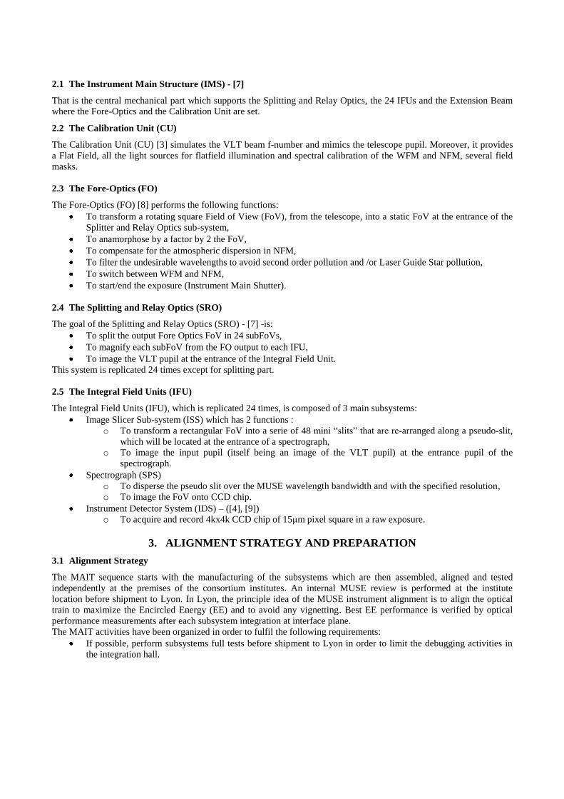
4.2.1 References and optical axis definition
The MUSE mechanical reference is the plane composed of the 4 FO feet and 2 holes available into 2 Fore Optics feet.
The reference system is measured with the Romer arm measuring device and takes as reference (accuracy<25µm) -
Figure 7.
Four optical Reference Targets are located onto Extension Beam (Figure 7). These targets are references for Internal
MUSE alignment.
Ref EB1 is located in the CU Pupil Plane. It is a perforated mirror with a target centred on it.
Ref EB2 is located in the CU Focal Plane. It is a perforated mirror with a target centred on it
Ref EB4 is located below the junction plate. Same design as Ref EB1&2
Mirror M3: This is a 310 x 60 x 50 mm thick mirror. One large target on a mechanical plate is composed of 4
hollow sub targets which is glued on its reflective surface. For that, the edges of mirror are the reference and the
target is glued on the mirror wrt these edges under 3D measuring machine. These sub targets are located at
different locations along y axis:
o M3Target1. It defines the VLT entrance optical axis which is the same as FO entrance optical axis.
o M3Target2. It defines the positioning of FO exit optical axis.
o M3Target3. It is located in the same location (x, y) as the 25th mirror of the Field Separator.
o M3Target4. It is located at the top of FSUnit.
These 4 optical Reference Targets are positioned wrt the MUSE mechanical references with the Romer arm measuring
device. The positioning errors are lower than 100µm and 2 arcmins.
Figure 7: Left: MUSE mechanical references. Right: MUSE optical references
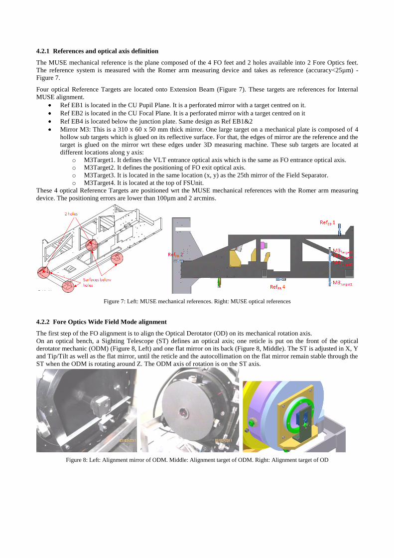
4.2.2 Fore Optics Wide Field Mode alignment
The first step of the FO alignment is to align the Optical Derotator (OD) on its mechanical rotation axis.
On an optical bench, a Sighting Telescope (ST) defines an optical axis; one reticle is put on the front of the optical
derotator mechanic (ODM) (Figure 8, Left) and one flat mirror on its back (Figure 8, Middle). The ST is adjusted in X, Y
and Tip/Tilt as well as the flat mirror, until the reticle and the autocollimation on the flat mirror remain stable through the
ST when the ODM is rotating around Z. The ODM axis of rotation is on the ST axis.
Figure 8: Left: Alignment mirror of ODM. Middle: Alignment target of ODM. Right: Alignment target of OD

Then the reticle and the flat mirror are removed, the OD is mounted in its mechanic. A target located at the objet plane of
the OD positioned using the ST, and a tool called Pupil/Image Check (PIC) tool is inserted. This tool allows to measure
both image and pupil wobbles when the OD rotates. In MUSE, it is located between NFM switching unit and the first
anamorphic mirror (FOaM1) on IRLOS interface. It is placed onto a translation stage in order to translate it onto MUSE
optical beam whenever that will be necessary. It stays in the MUSE instrument during its lifetime to periodically check
the positioning of MUSE at Nasmyth focus or after an earthquake. The OD is aligned by minimizing both wobbles. It is
a sensitivity task as both wobble are coupled at the level of the OD. We obtain an image wobble of 0.62mm in diameter
and a pupil wobble of 0.080mm for a specification of 1.6mm and 0.320mm respectively.
The final step for the OD setup is to create a reference target in front of the OD that will be used for the alignment of the
OD on the Extension Beam. This target consists in a reticle and a flat mirror attached to the ODM (Figure 8, Right).
The second step of the FO alignment process is to create one Optical Axis (OA) that will be the reference for the OD
alignment on the EB. The ST and 2 adjustable Pentaprisms (PP1 and2) are used to create this OA (Figure 9, Left).
RefEB1, RefEB2 and M3 are used to align the Pentaprisms, nevertheless as each reference target is not perfect; It is not
possible to create an OA that is centered and perpendicular onto each target. RefEB1 and M3 are the most important
references so RefEB2 has been partially used.
Then, the 2 Anamorphic Mirrors have been inserted in the optical path and aligned in order that M3 is centrered (Figure
9, Right). Because of the anamorphose, it is not possible to see the autoreflexion of RefEB1 onto M3 with the ST. To
cope with this, the FO Field Lens was inserted in the optical path, if M3 stays centered, it means the optical axis is
orthogonal to the FO Field Lens and thus to M3. We obtain then an OA with a decenter below 0.3mm and with a tilt
below 1arcmin wrt M3.
Finally, the OD is inserted and aligned in X, Y and Tip/tilt using its reference target, with the already know criteria:
reticle and autocollimation seen stable with the ST when the OD rotates. The alignment target is then removed and final
check is performed looking at M3 wobble and the autocollimation cross wobble with the PIC tool. The pupil wobble has
increased to 0.120µm and M3 reaches now 1.4mm which is compatible to 0.62mm of residual wobble and the decenter
of 0.3mm of the OA wrt M3.
Figure 9: Left: Definition of optical axis. Right: Alignment of 2 anamorphic mirrors
4.2.3 Calibration Unit alignment
Once the FO Anamorphic Mirrors and the OD are aligned, the ST, RefEB1 and 2 and the Pentraprisms mount are
removed so that the CU Integrating Sphere, the 2 CU Folding Mirrors, the CU Relay Lens and the CU stages with its set
of Calibration Masks can be mounted (Figure 10). The alignment process is simple and consists to align the CU optical
beam onto the OD optical axis by minimizing both image and pupil wobbles seen by the PIC. Here wobbles are
decoupled: the folding mirror before the CU mask along the optical path only affects the pupil, The CU mask decenters
in X and Y helps to align the FoV without affecting the pupil. The 2nd FM stays in a fixed position.
Finally, the focus is done thanks to the Z translation stage of the CU Mask using a camera at the FO exit (with the FO
Field Lens included). This adjustment takes into account the missing glass thickness of 20mm of SILICA that exists in
the FSU assembly.
A wobble image of 1.1mm and pupil wobble of 0.201mm are measured which is compliant with requirements (1.6mm in
Fov and 0.320mm in pupil). The FSUnit can be inserted and aligned and after the Extension Beam can be move on the
Instrument Main Structure (Figure 10, Right).
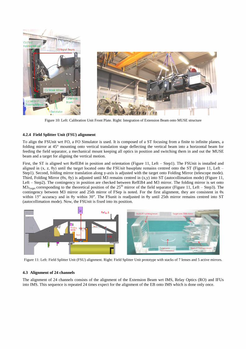
Figure 10: Left: Calibration Unit Front Plate. Right: Integration of Extension Beam onto MUSE structure
4.2.4 Field Splitter Unit (FSU) alignment
To align the FSUnit wrt FO, a FO Simulator is used. It is composed of a ST focusing from a finite to infinite planes, a
folding mirror at 45° mounting onto vertical translation stage deflecting the vertical beam into a horizontal beam for
feeding the field separator, a mechanical mount keeping all optics in position and switching them in and out the MUSE
beam and a target for aligning the vertical motion.
First, the ST is aligned wrt RefEB4 in position and orientation (Figure 11, Left – Step1). The FSUnit is installed and
aligned in (x, z, θy) until the target located onto the FSUnit baseplate remains centred onto the ST (Figure 11, Left –
Step1). Second, folding mirror translation along y-axis is adjusted with the target onto Folding Mirror (telescope mode).
Third, Folding Mirror (θx, θy) is adjusted until M3 remains centred in (x,y) into ST (autocollimation mode) (Figure 11,
Left – Step2). The contingency in position are checked between RefEB4 and M3 mirror. The folding mirror is set onto
M3Target corresponding to the theoretical position of the 25th
mirror of the field separator (Figure 11, Left – Step3). The
contingency between M3 mirror and 25th mirror of FSep is noted. For the first alignment, they are consistent in θx
within 15″ accuracy and in θy within 30″. The FSunit is readjusted in θy until 25th mirror remains centred into ST
(autocollimation mode). Now, the FSUnit is fixed into its position.
Figure 11: Left: Field Splitter Unit (FSU) alignment. Right: Field Splitter Unit prototype with stacks of 7 lenses and 5 active mirrors.
4.3 Alignment of 24 channels
The alignment of 24 channels consists of the alignment of the Extension Beam wrt IMS, Relay Optics (RO) and IFUs
into IMS. This sequence is repeated 24 times expect for the alignment of the EB onto IMS which is done only once.

4.3.1 Integration of Extension Beam wrt IMS
The Extension Beam is installed thanks to pins precisely to +/-50µm in x, z and θy onto IMS with the crane (Figure 10).
The FM1 mapping consists of a process to optimize the FSUnit position and orientation wrt 24 channels. For that, five
reference spherical mounted reflectors (SMR) are located onto corresponding FM1 mirrors of channels n°18, 19, 21, 22,
23 (Figure 12). They are located within mechanical tolerances wrt IMS positioning and checked with laser tracker. They
have to be placed at different distance from the FSep to allow reasonable angular resolution. Thanks to the FO-
Simulator, which has been aligned with mechanical references of the Extension Beam (§4.2.4), the offset in x and y axes
is measured with SMR and compared with their respective decenters (Figure 12). If the optical check is out of
specification for the SRO acceptance range (±1mm, ±0.5°), there are 2 options for last adjustments. First, FSUunit is
readjusted in x, z and θy wrt FM1 mapping until it stays inside FO tolerances. Second, the EB is adjusted wrt IMS in y,
θx and θz by shimming. The FSUnit is aligned with respect to the M3 mirror in theta X. Then X, thetaY and Z degrees of
freedom have been tuned to reach the best compromise on the 5 paths available of the FSO prototype. The Figure 12
shows the results of FM1 mapping of the autoreflection on the FO simulator of the laser tracker ball positioned at each
FM1 mirror. The alignment in X and Y is inferior 0.5mm except for Y of path 18 and 22 where a shimming of the mirror
has to be anticipated.
Figure 12: Left: SRO Pre-alignment with FO-Simulator. Right: Results of FM1 mapping onto channels n°18, 19, 21, 22, 23
4.3.2 Alignment of Relay Optics
The main tool to align the Relay Optics is the IFU Simulator. It allows to:
Pre-align the SRO with FO-Simulator (±1mm; ±0.5°),
Align the FoV and Pupil coming from {CU+FO+SRO} (±0.1mm; ±0.02°),
Perform image quality of {CU+FO+SRO},
See any vignetting into all SRO optical components planes.
The IFU Simulator is composed of (Figure 13):
Same interface as IFU called IFU Flange which is the reference for SRO/IFU interface,
A detection module with a camera objective, a teleconverter x2 and Apogee CCD to record the FoV and pupil.
This detection could sight from IFU input plane to infinity,
A target located into the IFU entrance plane. The central part (target and mirror) is only dedicated to the SRO
pre-alignment alone with the FO-Simulator. The extremity part is dedicated to {CU+FO+SRO} alignment,
image quality and vignetting tests.
The IFU Simulator is aligned and characterized independently using Romer arm measuring device for positioning and
autocollimator for orientation. The IFU Simulator is inserted into the IMS at the respective channel position. The mirror
of the FO-Simulator is slided vertically to sub field slice of the field separator according to position of the IFU
Simulator. FM1 and a calibrated target mounted onto FM2 position are installed. The ST is focused onto this target. FM1

is aligned in (z, θx, θy) until the target is centred onto ST. FM2 is installed onto IMS. FM2 is aligned in (z, θx, θy) in
using an iterative process with the ST focused either onto IFU Simulator target or at the infinity.
The imaging optics (singlets and doublets) of the corresponding relay path are inserted into the beam before the last
alignment step takes place. In order to mimic the original light path, the calibration unit CU and the FO is used for
illumination. Illuminating by this way will take into account residual errors of the Fore Optics in telecentricity that is
compensated out by the SRO optics. Observing is done with the IFU-Simulator. The fine adjustment does concentrate on
the folding mirrors FM1&2 of SRO that will feed the image slicer of each IFU. The tolerances of the imaging lenses are
not very tight, therefore mechanical tolerances are sufficient and do not need extra alignment. Fine-adjustment is
performed into the relay path by squaring up and centering the beam on the IFU-simulator with FM1/FM2 (z, θx, θy) in
few iterative processes.
For the first channel alignment, the position of pupil and field is within specification (<0.1mm; <1 arcmin) except for the
θz position of the field (Figure 13, Right): 18 arcmin remain instead of the ±1.5 arcmin specified. It should mainly come
from the FSep mirror angle, could also get a combined impact from the FM1 and FM2 misalignment. It is a complex
procedure to identify. At the present time, it is still investigated. The Figure 13 shows that there is no vignetting onto
SRO channel and measured PSF is 95% of ensquared energy into one MUSE spaxel which is compliant with
requirement of 90%.
Figure 13 : Left: General View of IFU Simulator. Right: Results of SRO Alignment with IFU Simulator: FoV and Pupil Centering,
PSF and vignetting
4.3.3 Integration of IFU into IMS
No alignment is done when the IFU is inserted into
structure due to functionality of the IFU Simulator
because the same reference IFU Flange is used. All
IFUs are composed of one Image Slicer Subsystem
(ISS), one Spectrograph (SPS), and one Detector Vessel
(DV). Each of these subsystems is assembled and tested
before to be integrated into the IFU ([10] and [11]). To
validate independently each IFU, the same tools that
were mounted onto IMS are used (replica of IMS
mechanical interface and alignment of Illumination
Unit with the IFU Simulator). Thanks to this
philosophy, no further alignment needs to be done after
the IFU is inserted. Nevertheless a dedicated tool,
named IFU Positioning (Figure 14), is needed. This tool
allows to insert each IFU at its corresponding z-angle
and to insure a perfect positioning (<30µm) and
orientation (<30”). This step is duplicated 24 times.
Figure 14: IFU Insertion onto IMS with IFU Positioning Tool
4.4 Alignment of MUSE wrt VLT Simulator or Telescope
That is the last step of the MUSE alignment
corresponding to the alignment of MUSE wrt VLT
Simulator. The FO Pupil&Image Check (§ 4.2.2) is set
in position in order to see the pupil and field coming
from the CU. MUSE is tilted and translated until there
is the superimposition of pupils and fields coming from
CU and VLT Simulator. The adjustments available for
MUSE are the same as for the IMS before (§4.1).
Figure 15: Alignment of MUSE wrt VLT Simulator
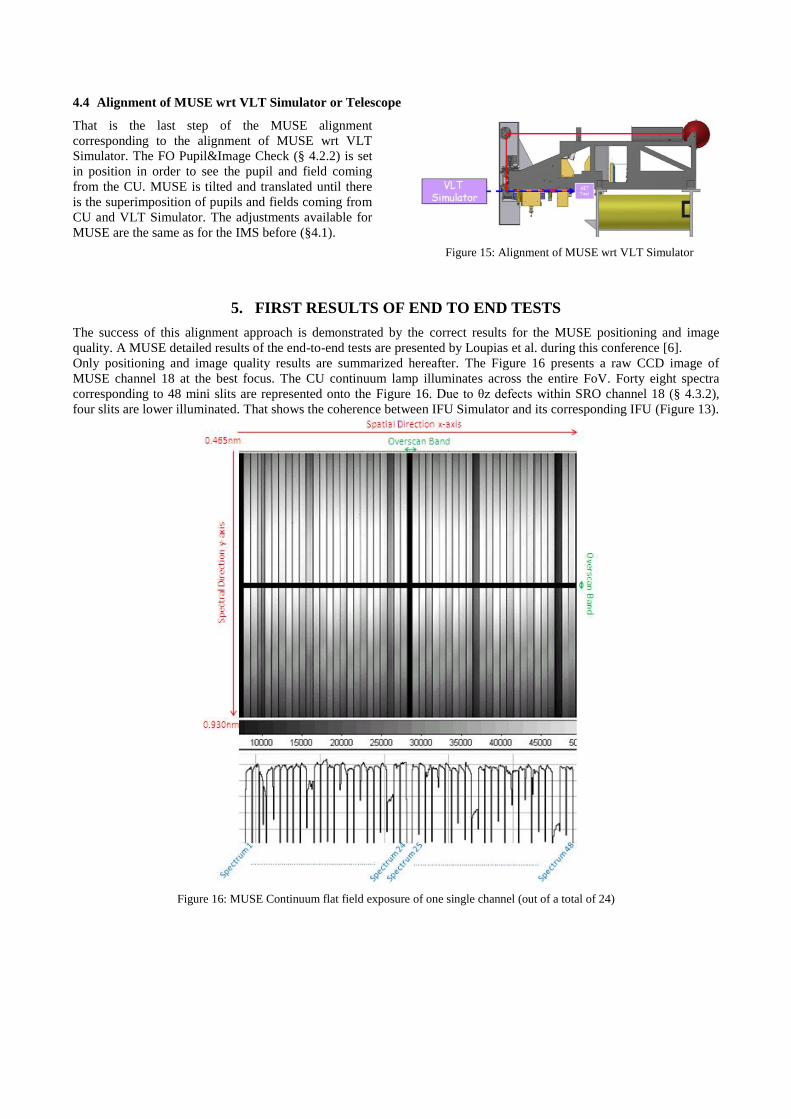
5. FIRST RESULTS OF END TO END TESTS
The success of this alignment approach is demonstrated by the correct results for the MUSE positioning and image
quality. A MUSE detailed results of the end-to-end tests are presented by Loupias et al. during this conference [6].
Only positioning and image quality results are summarized hereafter. The Figure 16 presents a raw CCD image of
MUSE channel 18 at the best focus. The CU continuum lamp illuminates across the entire FoV. Forty eight spectra
corresponding to 48 mini slits are represented onto the Figure 16. Due to θz defects within SRO channel 18 (§ 4.3.2),
four slits are lower illuminated. That shows the coherence between IFU Simulator and its corresponding IFU (Figure 13).
Figure 16: MUSE Continuum flat field exposure of one single channel (out of a total of 24)

For the WFM, the image quality has been measured using the Calibration Unit [3] that illuminates a grid of pinholes with
spectral lamps (HgCd, Ne and Xe). These spots are re-images through the entire optical path of channel 18 and the
resulting PSF is measured at the final detector plane. The MUSE Image Quality is within the requirements (Figure 17)
but it needs to be determined for all other channels and re-measured after the retrofits are done.
CCD area EE of IFU itself EE of Channel_18 EE Spec
465 nm < λ < 600 nm 1.30 pixel 1.85 pixel 2.20 pixel
600 nm < λ < 800 nm 1.18 pixel 1.48 pixel 1.90 pixel
800 nm < λ < 930 nm 1.37 pixel 1.73 pixel 1.78 pixel
Figure 17: MUSE Image Quality onto Channel 18
6. CONCLUSIONS AND FUTURE DEVELOPMENTS
The first integration and alignment of MUSE main opto-mechanical subsystems validates global optical design, MAIT
process and few top level performances. In the present case, this first MUSE alignment reveals a certain number of
validations which are very encouraging on the road towards the official Preliminary Acceptance in Europe through ESO.
Nevertheless, some non compliances mostly linked to FSO defects have been identified and should be solved for the next
steps.
The MAIT process has been demonstrated to be feasible. No major alignment showstoppers have been identified and it
can be concluded that the MUSE alignment process works well. A huge experience has been collected from this MUSE
first channel alignment and tests. Some modifications on alignment tools and on the process have been identified in order
to optimize the final alignment onto the telescope. The integration of the 23 remaining channels needs to be done
following the now established procedure.
ACKNOWLEDGMENT
We thank CNRS/INSU and University Claude-Bernard Lyon I for their strong support to the MUSE project.
REFERENCES
[1] Bacon R. "The second generation VLT instrument MUSE: final assembly in Europe and performance
assessment", Proc SPIE 8446-19, (2012)
[2] Caillier P. et al., "The MUSE project face to face with reality", Proc SPIE 8449-36, (2012)
[3] Kelz A. et al., "Development and performance of the MUSE calibration unit", Proc. SPIE 8446-222, (2012)
[4] Lizon J.L. et al., "A series of detector systems for MUSE", Proc SPIE 8446-192, (2012)
[5] Lizon J.L. et al., "Detector vacuum and cryogenic system for MUSE", Proc SPIE 8446-217, (2012)
[6] Loupias M. et al, "MUSE instrument global performance test", Proc SPIE 8446-224, (2012)
[7] Nicklas H. et al., "Performance of the main instrument structure and the optical relay system of MUSE", Proc
SPIE 8446-223, (2012)
[8] Parès L. et al., "Fore-optics of the MUSE instrument", Proc. SPIE 8446-220, (2012)
[9] Reiss R. et al., "The MUSE instrument detector system", Proc. SPIE 8446-98, (2012)
[10] Laurent, F. et al., “MUSE integral field unit: test results on the first out of 24”, Proc. SPIE, 7739-147, (2010)
[11] Renault, E. et al., “Optomechanical system of AIT tools to perform tests and integrations of 24 IFU”, Proc.
SPIE, 7739-124, (2010)
[12] Kosmalski, J. et al., “Optical Design of the VLT/MUSE instrument”, Proc. SPIE, 8167-41, (2011)