municipal advisory board - plastics pipe institute · · 2015-11-142 foreword this procedure was...
TRANSCRIPT

MAB Generic Electrofusion Procedure for Field Joining of 12 Inch and Smaller Polyethylene (PE) Pipe
First edition approved by Municipal Advisory Board on Nov. 5, 2015, in Casselberry, FL.
© Plastics Pipe Institute, 2015
Municipal Advisory Board Established May 1, 2008 at the University of Texas, Arlington
1
CONTENTS
FOREWORD ............................................................................................................................. 2
HISTORY ................................................................................................................................... 3
SCOPE ...................................................................................................................................... 3
I. INTRODUCTION ............................................................................................................ 4
II. JOBSITE PREPARATION ............................................................................................. 4
III. FITTING STORAGE AND HANDLING ........................................................................... 5
IV. REQUIRED TOOLS ....................................................................................................... 5
V. PIPE PREPARATION .................................................................................................... 8
VI. FITTING CLAMPING ....................................................................................................10
VII. CONTROL BOX ............................................................................................................11
VIII. POWER REQUIREMENTS ...........................................................................................12
IX. FUSION PARAMETERS ...............................................................................................13
X. ELECTROFUSION INSTALLATION TRAINING PROCEDURES .................................14
XI. FIELD GUIDE FOR ELECTROFUSION COUPLING INSTALLATION .........................22
XII. FIELD GUIDE FOR ELECTROFUSION SADDLE INSTALLATION ..............................24
XIII. FREQUENTLY ASKED QUESTIONS ...........................................................................25
XIV. OPERATOR TRAINING AND QUALIFICATION GUIDELINES ....................................28
Appendix A – List of Electrofusion Companies ....................................................................34
Appendix B - Generic Electrofusion Operator Training & Qualification Section ................35
Appendix C – Sample Test .....................................................................................................36
2
FOREWORD
This procedure was developed by the Municipal Advisory Board and published with the technical help of the members of the PPI (Plastics Pipe Institute, Inc.). The members have shown their interest in quality products by assisting independent standards-making and user organizations in the development of standards, and also by developing reports on an industry-wide basis to help engineers, code officials, specifying groups, and users.
The purpose of this technical report is to provide important information available to the Municipal Advisory Board (MAB) on particular aspects of polyethylene pipe electrofusion to engineers, users, contractors, code officials, and other interested parties. More detailed information on its purpose and use is provided in the document itself.
This report has been prepared by Municipal Advisory Board members and associates as a service to the industry. The information in this report is offered in good faith and believed to be accurate at the time of its preparation, but is offered “as is” without any express or implied warranty, including WARRANTIES OF MERCHANTABILITY AND FITNESS FOR A PARTICULAR PURPOSE. Consult the manufacturer for more detailed information about the particular joining procedures to be used with its piping products. Any reference to or testing of a particular proprietary product should not be construed as an endorsement by the Municipal Advisory Board, or the Plastics Pipe Institute, Inc., which do not endorse the proprietary products or processes of any manufacturer. The information in this report is offered for consideration by industry members in fulfilling their own compliance responsibilities. Municipal Advisory Board and the Plastics Pipe Institute, Inc., assume no responsibility for compliance with applicable laws and regulations.
The Municipal Advisory Board serves as an independent, non-commercial adviser to the M & I Division of the Plastics Pipe Institute. Once adopted, MAB intends to revise this report from time to time, in response to comments and suggestions from users of the report. Please send suggestions of improvements to Camille Rubeiz at [email protected].
ACKNOWLEDGEMENTS The Municipal Advisory Board would like to acknowledge the excellent contributions of the MAB Electrofusion Task Group for developing and leading this project:
1. Jeremy Harris, Plasson USA, Houston, TX
2. Casey Haynes, PE, City Utilities, Springfield, MO
3. Todd Jorgenson, PE, City of Austin, MN
4. Holly Link, Colorado Springs Utilities, CO
5. Jacob Nakano, City Utilities, Springfield, MO
6. Chad Owens, PE, City Utilities, Springfield, MO
7. Eric Shaffer, PE, City of Duluth, MN
8. Camille Rubeiz, PE, Plastics Pipe Institute, Irving, TX
9. Andrew Schipper, PE, City of Ft. Wayne, IN
10. Greg Scoby, PE, City of Palo Alto, CA (past) and Crossbore Consultants, CA
11. Jeff Wright, Georg Fischer Central Plastics, Shawnee, OK

3
HISTORY
In 2014, representatives of the Municipal Advisory Board (MAB) requested assistance in creating greater uniformity in the joining procedures utilized by municipal utilities in the electrofusion of polyethylene (PE) piping products for water and waste water applications. Users reported the proliferation of similar but slightly varying joining procedures from individual electrofusion fitting and equipment producers. The slight differences in the various procedures made it more difficult for system operators and installers to qualify persons with appropriate training and experience in the use of these procedures. It was even more difficult for system operators to inspect for and enforce that proper joining procedures were being followed.
In response to this request, MAB established a task group to develop a generic electrofusion procedure for the joining of polyethylene piping and a guide for inspection to ensure that proper procedures are in place and being followed. The result of that task group effort is this document.
In the spirit of complying with the above request, companies that manufacture electrofusion products and equipment reviewed existing procedures, agreed on common best practices, and combined experiences and knowledge to educate and train installers. Thus, this publication provides a uniform electrofusion joining procedure to provide greater consistency, and to facilitate the pipeline operator’s efforts to qualify the installer, reduce cost, and simplify inspections. Refer to Appendix A for a list of electrofusion companies that endorsed these generic practices for use with their fittings.
SCOPE
The program undertaken by the MAB Task Group combined common installation practices shared by multiple manufacturers into a single format. The goal is to provide clear direction and common procedures for proper pipe preparation, fitting-to-pipe assembly, and installation of electrofusion fittings on 12 inch or smaller pipe. An additional goal is to provide clear inspection criteria for installer qualification, installation acceptance by inspection, and answers to frequently asked questions. The size range was limited to 12 inch or smaller due to differences in installation procedures for larger diameters, commonly accepted as 14 inch or larger. For installation of larger electrofusion couplings, the user can reference PPI TN-34 INSTALLATION GUIDELINES FOR ELECTROFUSION COUPLINGS 14 INCH AND LARGER.
The Municipal Advisory Board hopes that the inherent value of greater uniformity will provide all the incentive necessary for companies to evaluate the procedure as a first option for electrofusion joining of its PE piping products. Use of this procedure is obviously not mandatory, and every electrofusion fitting producer, equipment manufacturer, and pipeline operator retains the option of developing different procedures for its particular products and pipelines. However, MAB believes that its work in developing this procedure as a candidate for widespread acceptance throughout the industry will lead to greater efficiency, simplicity, and understanding in this area and promote the use of effective, qualified procedures for electrofusion joining of PE pipe.
4
I. INTRODUCTION
Electrofusion joining of PE pressure pipe has been commonly used in North America for over 30 years. ASTM standard specifications for materials (ASTM D3350), performance (ASTM F1055), and installation practice (ASTM F1290) have been in publication for many years. All electrofusion fittings should be marked to indicate that they meet the design and performance requirements of ASTM F1055 before being considered for use. Additional markings may be included to indicate that other performance and health effect requirements are satisfied, such as AWWA C906 and NSF 61. Since each fitting manufacturer may have slightly varying geometrical designs, and each manufacturer is responsible for establishing safe installation temperature limits, it is also common that installation instructions can vary from one manufacturer to another. Although instructions can vary, all fitting designs share some common requirements for installation and all manufacturer’s instructions include these same requirements.
Proper installation techniques, installer understanding of and training to these techniques, and effective examination before installation are key to a successful installation. This document provides detailed instructions for each key step to a successful installation, why each step is important, and how to tell if the requirements of each step have been accomplished.
II. JOBSITE PREPARATION
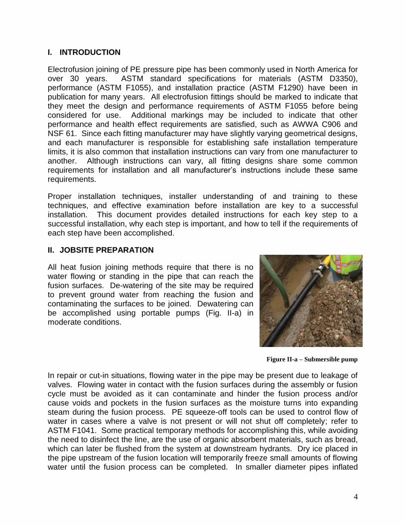
All heat fusion joining methods require that there is no water flowing or standing in the pipe that can reach the fusion surfaces. De-watering of the site may be required to prevent ground water from reaching the fusion and contaminating the surfaces to be joined. Dewatering can be accomplished using portable pumps (Fig. II-a) in moderate conditions.
Figure II-a – Submersible pump
In repair or cut-in situations, flowing water in the pipe may be present due to leakage of valves. Flowing water in contact with the fusion surfaces during the assembly or fusion cycle must be avoided as it can contaminate and hinder the fusion process and/or cause voids and pockets in the fusion surfaces as the moisture turns into expanding steam during the fusion process. PE squeeze-off tools can be used to control flow of water in cases where a valve is not present or will not shut off completely; refer to ASTM F1041. Some practical temporary methods for accomplishing this, while avoiding the need to disinfect the line, are the use of organic absorbent materials, such as bread, which can later be flushed from the system at downstream hydrants. Dry ice placed in the pipe upstream of the fusion location will temporarily freeze small amounts of flowing water until the fusion process can be completed. In smaller diameter pipes inflated
5
latex balloons also provide good temporary stoppage of trickling water. The balloon will burst during pressure testing and can be flushed from the system at a downstream outlet.
Electrofusion fittings can be installed in ambient temperatures as recommended by the manufacturer. A typical qualified temperature range for installation is 14°F minimum to 113°F maximum. Some manufacturers have lower and/or higher temperature limits and will state their qualified range in the technical specifications, contact the fitting manufacturer to verify.
III. FITTING STORAGE AND HANDLING
Electrofusion fittings are packaged in sealed plastic bags as protection against accumulation of dust, dirt, and contamination. The bag should remain in place during normal handling and should only be removed during installation. Fittings are also typically boxed to protect against other sources of degradation, such as oxidation due to UV exposure over long periods of storage. Fittings should always be stored indoors in their original packaging until installation.
Black electrofusion fittings contain a 2% to 3% carbon black additive to protect against other UV effects and if stored indoors in their original packaging have a virtually unlimited shelf life.
Fittings with an unknown storage history or that have been exposed to questionable storage conditions should be evaluated through destructive testing of sample fusions. If fusion quality is shown to be affected, the fittings in question should not be installed.
Fittings should be inspected for damage before installing to ensure that connection points such as terminal pins have not been damaged from handling, that there is no visible damage to fusion surfaces or heating wires, and that no foreign materials are present on or near the fusion surfaces.
Fittings can be cleaned if incidental contact is made with the fusion surface. A suitable cleaning agent that contains no additives to hinder the fusion process must be used. 96% or greater concentration of Isopropyl alcohol, with no additional additives except water, is universally accepted as a good cleaning agent. Other cleaning agents may be acceptable and the fitting manufacturer should be consulted in case of questions.
DO NOT USE DENATURED ALCOHOL – Denatured alcohols may contain additives that can prevent fusion and should not be used.
IV. REQUIRED TOOLS
Proper tools are essential to a successful electrofusion installation. Tools include devices for measuring, marking, cutting, scraping, cleaning, clamping (which includes aligning and securing), re-rounding, and power delivery. At minimum, the following items should be accessible during installation:

6
A. Measuring: A tape measure (Fig. IV-a) or ruler for measurement of insertion (stab) depth of pipe ends inside a coupling. A circumferential wrap Pi tape for measurement of pipe diameter is also recommended.
Figure IV-a –Measuring Tape
B. Marking: A permanent visible marker. Markers should be visible on the pipe color (Fig. IV-b) being used. For black pipe, a silver colored Sharpie®, or equivalent, permanent marker works well. The marker dries fast and contains no oils or other ingredients that could accidentally contaminate a prepared pipe surface. Marks are needed to locate insertion depths and to use as a guide for pipe scraping effectiveness.
Markers that are slow-drying or contain oils that could be spread onto fusion surfaces should not be used.
Figure IV-b - Marking
C. Cutting: Devices that deliver a relatively clean and square cut (±3 degrees) on the pipe ends are recommended. Many suitable types of pipe cutters are commercially available that can be used for diameters of 12 inch and smaller (Fig. IV-c).
Figure IV-c – Pipe cutters (rotational, ratcheting, and guillotine style)
For larger diameters, a suitable saw (without lubricants) and a guide or guide marks can be used; reciprocating saws, circular saws with a coarse-tooth blade, hot saws, chop saws, and chain saws are commonly used for larger pipes with appropriate safety precautions and personal protective equipment. Cutting marks can made around the pipe using a 2 inch or wider strap or encirclement clamp as a guide so that the pipe can then be cut along the line as shown in Fig. IV-d.
Figure IV-d – Marking and cutting larger diameter pipes

7
D. Measuring pipe:
Diameter: Electrofusion fittings are designed for use on pipe made to standard 1.diameters in dimensions for Iron Pipe Size (IPS), Copper Tube Size (CTS), and Ductile Iron Pipe Size (DIPS). Pipe that is outside of the diameter tolerance band of the appropriate pipe standard should not be used. The following table (Table IV-a) can be used for reference when measuring pipe diameter to ensure that the pipe is within tolerance.
Table IV-a – Standard Pipe and Tubing Dimensions
(NOTE: For sizes larger than 12 inch, See PPI TN-34)
Roundness: Polyethylene is a flexible material. Pipe roundness (Fig III-e) can 2.be affected by a number of conditions to include manufacturing process conditions, coiling, storage/stacking, and soil load if buried.
The condition of pipe roundness can be expressed in two ways, “out-of roundness” or “ovality”, while both are referencing the same basic condition, it can sometimes be confusing:
Out-of-roundness is the difference in the maximum measured diameter minus the minimum measured diameter. The pipe can be measured with a tape measure or calipers to find the maximum (d1) and minimum (d2) diameter points. The out-of-roundness is calculated as d1- d2 as measured in the field.
Ovality is the difference between the maximum and minimum measured outside diameters expressed as a percentage. Ovality is calculated as (d1 – d2) / Daverage x 100.
Figure IV-e - Roundness Measurement

8
If severe enough, pipe out-of-roundness can have a negative effect on electrofusion joint quality. If the pipe is out-of-round, and is not corrected, the amount of gap between the pipe and fitting can be too large for the melt expansion to close and increase the difficulty of sliding the fitting onto the pipe.
Most often, 2” IPS and smaller diameter tubing is flexible enough that the coupling and alignment clamps will provide the necessary rounding forces and no other re-rounding device is needed.
For sizes equal to or larger than 3” IPS / DIPS, re-rounding clamps may be needed on either side of an electrofusion fitting to ensure that the gap between the pipe and fitting is not too large. Table IV-b can be used for guidance when re-rounding clamps are used:
Table IV-b – Maximum Out-of-Roundness (IPS/DIPS)
PIPE SIZE d1 - d2
3" .0625 or 1/16"
4" .0625 or 1/16"
6" .125 or 1/8"
8" .125 or 1/8"
10" .125 or 1/8"
12" .125 or 1/8"
Pipe scratches and/or gouges: Installation of pipe can cause surface scratches or gouges. Smaller scratches from dragging or normal handling are not problematic and will normally be removed during the pipe preparation process by scraping.
Gouges that are deeper than the scrape depth may also require extra attention when scraping the pipe to ensure that any debris or contaminates embedded in the gouges are removed; use of a hand tool to scrape the gouge may be necessary. If the gouge exceeds 10% of the pipe wall thickness, that pipe section should be cut out and replaced to maintain the maximum pressure rating of the pipe.
V. PIPE PREPARATION
Scraping: Pipe preparation is perhaps the most important and least understood aspect of making a sound electrofusion joint. Improper pipe preparation is overwhelmingly the leading cause of unsuccessful electrofusion joint attempts because the installer may not completely understand the goal of pipe scraping, which is to remove a thin layer of the outer pipe surface (see trouble-shooting section for more details) to expose clean virgin material beneath.
Pipe surfaces exhibit surface oxidation from the extrusion process, transportation, and outdoor exposure. Surface oxidation is a normal chemical reaction that results in a
9
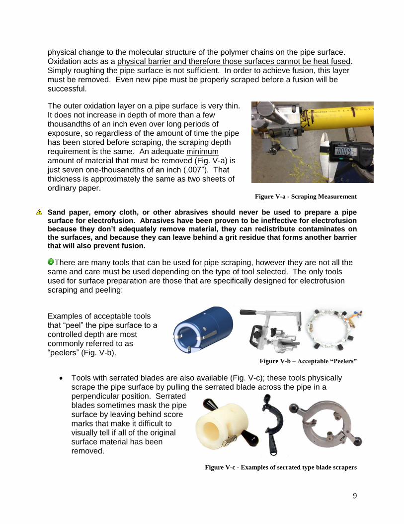
physical change to the molecular structure of the polymer chains on the pipe surface. Oxidation acts as a physical barrier and therefore those surfaces cannot be heat fused. Simply roughing the pipe surface is not sufficient. In order to achieve fusion, this layer must be removed. Even new pipe must be properly scraped before a fusion will be successful.
The outer oxidation layer on a pipe surface is very thin. It does not increase in depth of more than a few thousandths of an inch even over long periods of exposure, so regardless of the amount of time the pipe has been stored before scraping, the scraping depth requirement is the same. An adequate minimum amount of material that must be removed (Fig. V-a) is just seven one-thousandths of an inch (.007”). That thickness is approximately the same as two sheets of ordinary paper.
Figure V-a - Scraping Measurement
Sand paper, emory cloth, or other abrasives should never be used to prepare a pipe surface for electrofusion. Abrasives have been proven to be ineffective for electrofusion because they don’t adequately remove material, they can redistribute contaminates on the surfaces, and because they can leave behind a grit residue that forms another barrier that will also prevent fusion.
There are many tools that can be used for pipe scraping, however they are not all the same and care must be used depending on the type of tool selected. The only tools used for surface preparation are those that are specifically designed for electrofusion scraping and peeling:
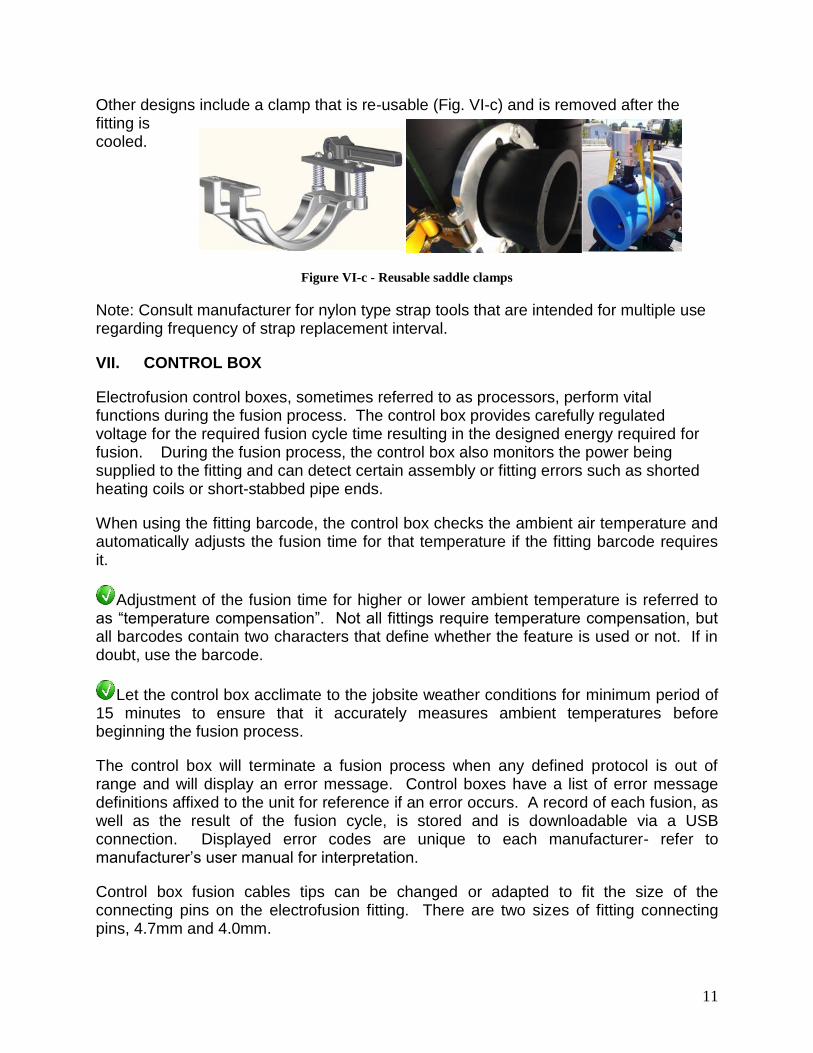
Examples of acceptable tools that “peel” the pipe surface to a controlled depth are most commonly referred to as “peelers” (Fig. V-b).
Figure V-b – Acceptable “Peelers”
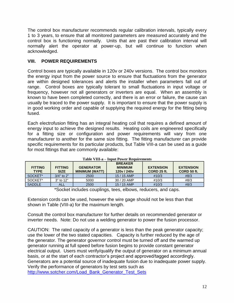
Tools with serrated blades are also available (Fig. V-c); these tools physically scrape the pipe surface by pulling the serrated blade across the pipe in a perpendicular position. Serrated blades sometimes mask the pipe surface by leaving behind score marks that make it difficult to visually tell if all of the original surface material has been removed.
Figure V-c - Examples of serrated type blade scrapers

10
It is strongly recommended that, no matter what type of tool is used, witness marks should be made on the pipe surface with a permanent marker prior to scraping so that any marking that remains after scraping is evidence that areas were missed or that more scraping is required.
Another type of tool is referred to as a “hand scraper”. These scrapers are not recommended (Fig. V-d) due to inconsistent surface preparation and difficulty in mastering skills required for uniform surface preparation.
Figure V-d – Not Recommended “Hand Scrapers”
Wood rasps and metal files are not acceptable scraping tools.
VI. FITTING CLAMPING
Electrofusion fittings generate significant pressure from thermal expansion during the melt phase of the fusion process. This melt pressure is an integral part of the fusion process and a designed function of the fitting and fusion parameter. Polyethylene is also a thermoplastic that softens when heated. As a result, all electrofusion fittings shall be installed with the use of alignment and restraining clamps. (Fig. VI-a)
Figure VI-a - Fitting Clamps
Use clamps on all coupling installation that will restrain the pipe ends from moving and keep the pipes in alignment. Some coupling clamp designs also serve to re-round the pipe when placed on either side of the fitting.
Saddles require clamps to secure the fitting to the main to prevent movement, restrain against generated melt pressure, and in some cases to form the fitting to the contour of the main. Saddles are designed to be used with a particular clamping device. Clamping devices are typically not interchangeable from one fitting design or main size to another. In some cases clamping devices may be a part of the fitting (commonly referred to as under-parts) that are intended to remain in place after fusion (Fig. VI-b). Specific instructions for clamping and/or fastener tightening are provided by the fitting manufacturer and must be followed.
Figure VI-b - Integral saddle clamps that remain in place after fusion
11
Other designs include a clamp that is re-usable (Fig. VI-c) and is removed after the fitting is cooled.
Figure VI-c - Reusable saddle clamps
Note: Consult manufacturer for nylon type strap tools that are intended for multiple use regarding frequency of strap replacement interval.
VII. CONTROL BOX
Electrofusion control boxes, sometimes referred to as processors, perform vital functions during the fusion process. The control box provides carefully regulated voltage for the required fusion cycle time resulting in the designed energy required for fusion. During the fusion process, the control box also monitors the power being supplied to the fitting and can detect certain assembly or fitting errors such as shorted heating coils or short-stabbed pipe ends.
When using the fitting barcode, the control box checks the ambient air temperature and automatically adjusts the fusion time for that temperature if the fitting barcode requires it.
Adjustment of the fusion time for higher or lower ambient temperature is referred to as “temperature compensation”. Not all fittings require temperature compensation, but all barcodes contain two characters that define whether the feature is used or not. If in doubt, use the barcode.
Let the control box acclimate to the jobsite weather conditions for minimum period of 15 minutes to ensure that it accurately measures ambient temperatures before beginning the fusion process.
The control box will terminate a fusion process when any defined protocol is out of range and will display an error message. Control boxes have a list of error message definitions affixed to the unit for reference if an error occurs. A record of each fusion, as well as the result of the fusion cycle, is stored and is downloadable via a USB connection. Displayed error codes are unique to each manufacturer- refer to manufacturer’s user manual for interpretation.
Control box fusion cables tips can be changed or adapted to fit the size of the connecting pins on the electrofusion fitting. There are two sizes of fitting connecting pins, 4.7mm and 4.0mm.
12
The control box manufacturer recommends regular calibration intervals, typically every 1 to 3 years, to ensure that all monitored parameters are measured accurately and the control box is functioning normally. Units that are past their calibration interval will normally alert the operator at power-up, but will continue to function when acknowledged.
VIII. POWER REQUIREMENTS
Control boxes are typically available in 120v or 240v versions. The control box monitors the energy input from the power source to ensure that fluctuations from the generator are within designed tolerances and alerts the installer when parameters fall out of range. Control boxes are typically tolerant to small fluctuations in input voltage or frequency, however not all generators or inverters are equal. When an assembly is known to have been completed correctly, and there is an error or failure, the cause can usually be traced to the power supply. It is important to ensure that the power supply is in good working order and capable of supplying the required energy for the fitting being fused.
Each electrofusion fitting has an integral heating coil that requires a defined amount of energy input to achieve the designed results. Heating coils are engineered specifically for a fitting size or configuration and power requirements will vary from one manufacturer to another for the same size fitting. The fitting manufacturer can provide specific requirements for its particular products, but Table VIII-a can be used as a guide for most fittings that are commonly available:
Table VIII-a – Input Power Requirements
FITTING TYPE
FITTING SIZE
GENERATOR MINIMUM (WATT)
BREAKER MINIMUM
120v / 240v EXTENSION CORD 25 ft.
EXTENSION CORD 50 ft.
SOCKET* 3/4" to 2" 2500 15 / 15 AMP #10/3 #8/3
SOCKET* 3" to 12" 5000 30 / 20 AMP #10/3 #8/3
SADDLE ALL 2500 15 / 15 AMP #10/3 #8/3
*Socket includes couplings, tees, elbows, reducers, and caps.
Extension cords can be used, however the wire gage should not be less than that shown in Table (VIII-a) for the maximum length.
Consult the control box manufacturer for further details on recommended generator or inverter needs. Note: Do not use a welding generator to power the fusion processor.
CAUTION: The rated capacity of a generator is less than the peak generator capacity; use the lower of the two stated capacities. Capacity is further reduced by the age of the generator. The generator governor control must be turned off and the warmed up generator running at full speed before fusion begins to provide constant generator electrical output. Users must verify/qualify the output of generator on a minimum annual basis, or at the start of each contractor’s project and approved/tagged accordingly. Generators are a potential source of inadequate fusion due to inadequate power supply. Verify the performance of generators by test sets such as http://www.sotcher.com/Load_Bank_Generator_Test_Sets

13
IX. FUSION PARAMETERS
Fusion parameters such as fusion time, voltage, and cooling time, can be entered into the control box by various means:
A. All electrofusion fittings have a barcode attached that contains all of the information needed by the control box to perform the fusion process. Barcodes contain additional information about the fitting manufacturer, fitting size, fitting resistance, and temperature correction values if required by the fitting manufacturer.
1. Codes are displayed on the fitting label in an interleaved barcode format that can be read by a barcode wand or hand-held scanner. Bar code scanners should be kept clean to insure proper working order.
2. Because of limitations in the number of characters allowed by the barcode standard, DIPS fittings may not accurately display sizing standard (DIPS) on EF processor. DIPS sizes may display as the metric (mm) equivalent, or as IPS. Consult EF processor or fitting manufacturer for further information.
3. The 24-digit numerical value is also printed on the label, either directly above or below the barcode (Fig. IX-a) that can be entered into the control box in in the event that the code cannot be scanned.
Figure IX-a – Barcode with Numerical Value
B. Identification resistors (Fig. IX-b) are supplied in some fitting designs that can be read by a compatible control box to automatically set the fusion time, voltage, and cooling time. The resistor pin is usually identified by a colored insert in the center of the pin that can be matched to a colored end of the control box cable.
Figure IX-b – Identification Resistor
C. Manual entry of fusion time and voltage entry may be possible if printed on the fitting label (Fig. IX-c). The fusion time is typically preceded by the word “WELD” or “FUSE” and displayed in seconds. The voltage is displayed and followed by “V”. It is always preferable to use the bar code method. All PE EF fittings are manufactured using PE 4710/PE100 and must be fusible to the piping system. Figure IX-c – Label for Manual Entry of Fusion Values
14
X. ELECTROFUSION INSTALLATION TRAINING PROCEDURES
A. COUPLING INSTALLATION:
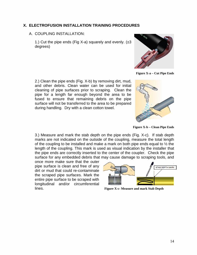
1.) Cut the pipe ends (Fig X-a) squarely and evenly. (±3 degrees)
Figure X-a – Cut Pipe Ends
2.) Clean the pipe ends (Fig. X-b) by removing dirt, mud, and other debris. Clean water can be used for initial cleaning of pipe surfaces prior to scraping. Clean the pipe for a length far enough beyond the area to be fused to ensure that remaining debris on the pipe surface will not be transferred to the area to be prepared during handling. Dry with a clean cotton towel.
Figure X-b – Clean Pipe Ends
3.) Measure and mark the stab depth on the pipe ends (Fig. X-c). If stab depth marks are not indicated on the outside of the coupling, measure the total length of the coupling to be installed and make a mark on both pipe ends equal to ½ the length of the coupling. This mark is used as visual indication by the installer that the pipe ends are correctly inserted to the center of the coupler. Check the pipe surface for any embedded debris that may cause damage to scraping tools, and once more make sure that the outer pipe surface is clean and free of any dirt or mud that could re-contaminate the scraped pipe surfaces. Mark the entire pipe surface to be scraped with longitudinal and/or circumferential lines. Figure X-c- Measure and mark Stab Depth
15
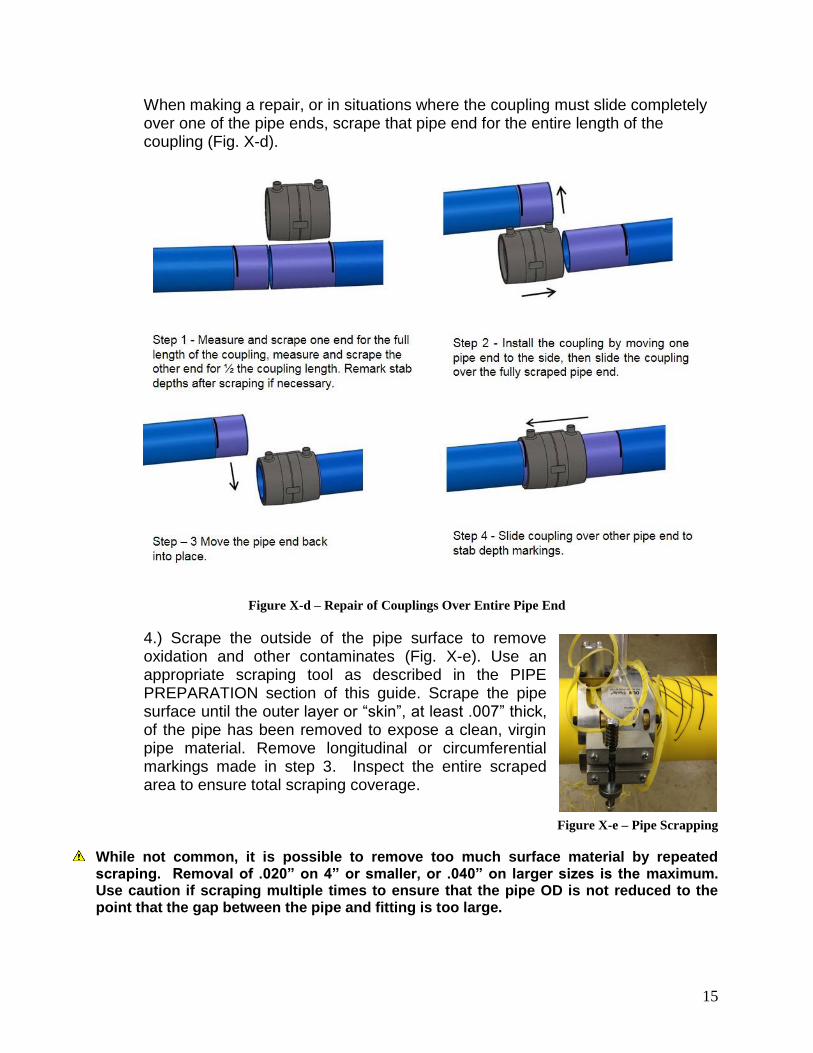
When making a repair, or in situations where the coupling must slide completely over one of the pipe ends, scrape that pipe end for the entire length of the coupling (Fig. X-d).
Figure X-d – Repair of Couplings Over Entire Pipe End
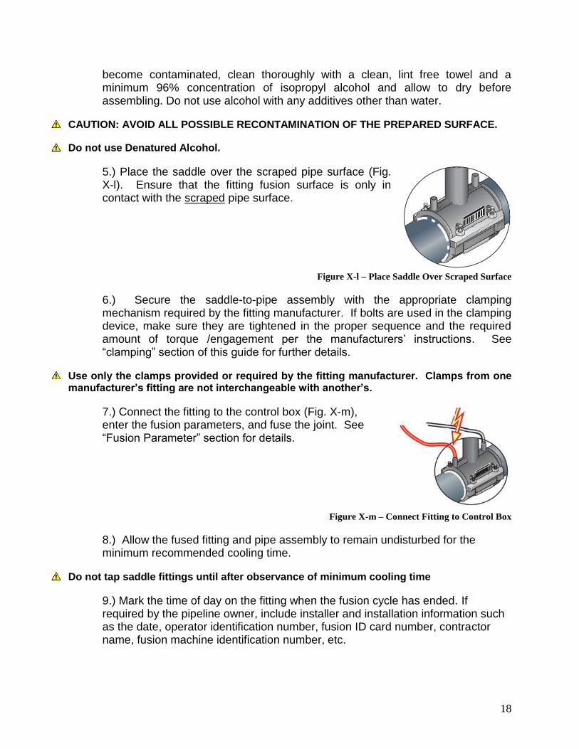
4.) Scrape the outside of the pipe surface to remove oxidation and other contaminates (Fig. X-e). Use an appropriate scraping tool as described in the PIPE PREPARATION section of this guide. Scrape the pipe surface until the outer layer or “skin”, at least .007” thick, of the pipe has been removed to expose a clean, virgin pipe material. Remove longitudinal or circumferential markings made in step 3. Inspect the entire scraped area to ensure total scraping coverage.
Figure X-e – Pipe Scrapping
While not common, it is possible to remove too much surface material by repeated scraping. Removal of .020” on 4” or smaller, or .040” on larger sizes is the maximum. Use caution if scraping multiple times to ensure that the pipe OD is not reduced to the point that the gap between the pipe and fitting is too large.

16
5.) Avoid touching the scraped pipe surface or the inside of the coupling as body oils and other contaminates can affect fusion joint performance. If the surfaces become contaminated, clean thoroughly with a clean, lint free towel and a minimum 96% concentration of isopropyl alcohol and allow to dry before assembling. Do not use alcohol with any additives other than water.
CAUTION: AVOID ALL POSSIBLE RECONTAMINATION OF THE PREPARED SURFACE.
Do not use Denatured Alcohol.
6.) Slide the coupling over the scraped pipe ends to the stab depth markings. If the pipe is out of round, a clamp can be used to re-round before sliding the coupling onto the pipe. If needed, a block of wood can be placed over the coupling end and a hammer can be used to drive the coupling onto the pipe. Use caution that the connecting pins are not damaged. Note: Pipe ends should be beveled on the outer edges when installing couplings that incorporate bare exposed heating wires to prevent snagging of wires on pipe edge.
When one of the pipes to be joined has limited movement capability, it may be necessary to slide the coupling onto the pipe for its full depth before placing the other pipe in place. If the full coupling must be placed on one pipe end, that pipe end should be cleaned and scraped for the full depth of the coupling to avoid contamination. The depth mark on the opposite pipe can be used for centering the coupling assuming that the two pipe ends are in contact (Fig X-f). Figure X-f – Center Couplings Between Depth Marks
7.) Clamp the pipe ends to align and secure the assembly (Fig. X-g).
Figure X-g – Clamp and Secure
8.) Connect the fitting to the control box (Fig. X-h), enter the fusion parameters (bar code scan the fitting), and fuse the joint. See “Fusion Parameter” section for details.
Figure X-h – Connect Fitting to Control Box

17
9.) Mark the time of day on the fitting when the fusion cycle has ended.
10). Allow the fused fitting and pipe assembly to remain clamped and undisturbed for the minimum recommended cooling time.
Cooling is a vital part of the fusion process. Proper cooling times must be observed and fused joints should not be disturbed until the proper cooling time has elapsed. See “clamping” section of this guide for further details.
B. SADDLE INSTALLATION:
1.) Clean the pipe (Fig. X-i) by removing dirt, mud, and other debris. Clean water can be used for initial cleaning of pipe surfaces prior to scraping. Clean the pipe for a length far enough beyond the area to be fused to ensure that remaining debris on the pipe surface will not be transferred to the area to be prepared during handling.
Figure X-i – Clean Pipe
2.) Mark the area on the pipe where the saddle is to be installed (Fig. X-j). This mark is used by the installer to indicate the approximate size of the area to be prepared. Check the pipe surface for any embedded debris that may cause damage to scraping tools, and once more make sure that the outer pipe surface is clean and free of any dirt or mud that could re-contaminate the scraped pipe surface. Mark the entire pipe surface to be scraped with longitudinal and/or circumferential lines.
Figure X-j – Mark Installation Area
3.) Scrape the outside of the pipe surface (Fig. X-k) to remove oxidation and other contaminates. Use an appropriate scraping tool as described in the PIPE PREPARATION section of this guide. Scrape the pipe surface until the outer layer or “skin”, at least .007” thick, of the pipe has been removed to expose a clean, virgin pipe material. Remove longitudinal or circumferential markings made in step 3. Inspect the entire scraped area to ensure total scraping coverage.
Figure X-k – Scrape Pipe
4.) Avoid touching the scraped pipe surface or the fitting fusion surface as body oils and other contaminates can affect fusion joint performance. If the surfaces
18
become contaminated, clean thoroughly with a clean, lint free towel and a minimum 96% concentration of isopropyl alcohol and allow to dry before assembling. Do not use alcohol with any additives other than water.
CAUTION: AVOID ALL POSSIBLE RECONTAMINATION OF THE PREPARED SURFACE.
Do not use Denatured Alcohol.
5.) Place the saddle over the scraped pipe surface (Fig. X-l). Ensure that the fitting fusion surface is only in contact with the scraped pipe surface.
Figure X-l – Place Saddle Over Scraped Surface
6.) Secure the saddle-to-pipe assembly with the appropriate clamping mechanism required by the fitting manufacturer. If bolts are used in the clamping device, make sure they are tightened in the proper sequence and the required amount of torque /engagement per the manufacturers’ instructions. See “clamping” section of this guide for further details.
Use only the clamps provided or required by the fitting manufacturer. Clamps from one manufacturer’s fitting are not interchangeable with another’s.
7.) Connect the fitting to the control box (Fig. X-m), enter the fusion parameters, and fuse the joint. See “Fusion Parameter” section for details.
Figure X-m – Connect Fitting to Control Box
8.) Allow the fused fitting and pipe assembly to remain undisturbed for the minimum recommended cooling time.
Do not tap saddle fittings until after observance of minimum cooling time
9.) Mark the time of day on the fitting when the fusion cycle has ended. If required by the pipeline owner, include installer and installation information such as the date, operator identification number, fusion ID card number, contractor name, fusion machine identification number, etc.
19
Cooling is a vital part of the fusion process. Proper cooling times must be observed. See “clamping” section of this guide for further details.
C. INSTALLATION INSPECTION CHECKLIST:
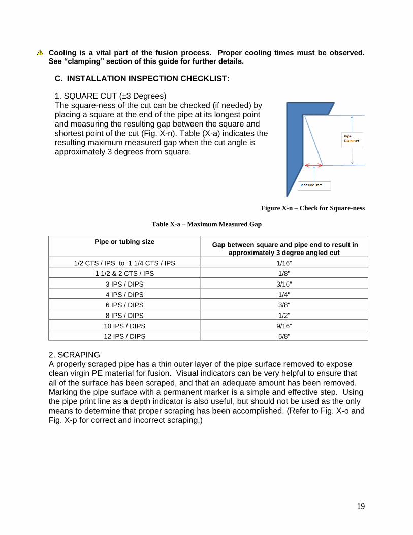
1. SQUARE CUT (±3 Degrees) The square-ness of the cut can be checked (if needed) by placing a square at the end of the pipe at its longest point and measuring the resulting gap between the square and shortest point of the cut (Fig. X-n). Table (X-a) indicates the resulting maximum measured gap when the cut angle is approximately 3 degrees from square.
Figure X-n – Check for Square-ness
Table X-a – Maximum Measured Gap
Pipe or tubing size
Gap between square and pipe end to result in
approximately 3 degree angled cut
1/2 CTS / IPS to 1 1/4 CTS / IPS 1/16"
1 1/2 & 2 CTS / IPS 1/8"
3 IPS / DIPS 3/16"
4 IPS / DIPS 1/4"
6 IPS / DIPS 3/8"
8 IPS / DIPS 1/2"
10 IPS / DIPS 9/16"
12 IPS / DIPS 5/8"
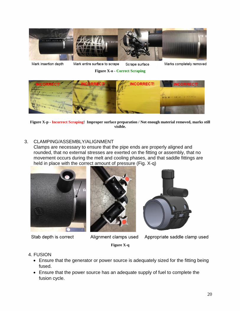
2. SCRAPING A properly scraped pipe has a thin outer layer of the pipe surface removed to expose clean virgin PE material for fusion. Visual indicators can be very helpful to ensure that all of the surface has been scraped, and that an adequate amount has been removed. Marking the pipe surface with a permanent marker is a simple and effective step. Using the pipe print line as a depth indicator is also useful, but should not be used as the only means to determine that proper scraping has been accomplished. (Refer to Fig. X-o and Fig. X-p for correct and incorrect scraping.)
20
Figure X-o - Correct Scraping
Figure X-p - Incorrect Scraping! Improper surface preparation / Not enough material removed, marks still
visible.
CLAMPING/ASSEMBLY/ALIGNMENT 3.
Clamps are necessary to ensure that the pipe ends are properly aligned and rounded, that no external stresses are exerted on the fitting or assembly, that no movement occurs during the melt and cooling phases, and that saddle fittings are held in place with the correct amount of pressure (Fig. X-q)
Figure X-q
4. FUSION
Ensure that the generator or power source is adequately sized for the fitting being
fused.
Ensure that the power source has an adequate supply of fuel to complete the
fusion cycle.

21
Ensure that any extension cords are appropriately sized for the fitting being fused.
See previous comments on generator.
5. CLAMPING Ensure that the proper clamps are in use and that the joint assembly is properly aligned. 6. COOLING Mark the time on or near the fitting to indicate when the minimum cooling time has elapsed. This will prevent inadvertent movement or removal of the assembly and/or clamps. If required by the pipeline owner, include installer and installation information such as the date, operator identification number, fusion ID card number, contractor name, fusion machine identification number, etc.
Do not allow pipe and fitting to be moved or exposed to stress before the minimum cooling time has elapsed!
22
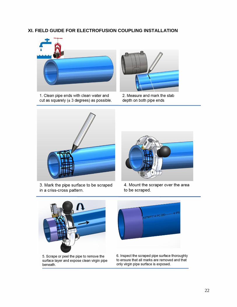
XI. FIELD GUIDE FOR ELECTROFUSION COUPLING INSTALLATION

23
24
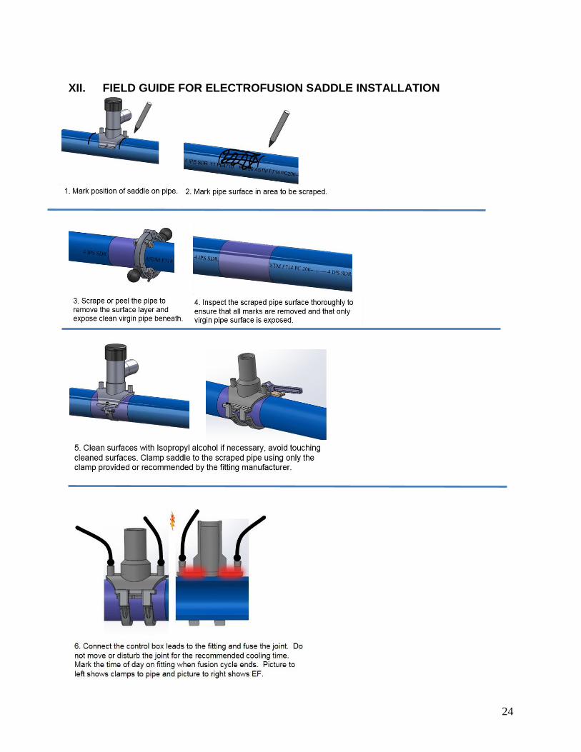
XII. FIELD GUIDE FOR ELECTROFUSION SADDLE INSTALLATION

25
XIII. FREQUENTLY ASKED QUESTIONS
What pipes can be fused with electrofusion fittings? A. Electrofusion fittings are compatible with pipe dimensions conforming to 1.
ASTM D2513, F714 and D3035. Fittings are typically compatible with pipes with a SDR or DR range of 9 to 2.
17. Other wall thickness ranges and pressure ratings may also apply. Consult the specific fitting manufacturer for details.
Electrofusion fittings are fusible to PE 2406/2708 and 3.PE3408/3608/3708/3710/4710 pipes.
What are the power requirements? B.
A reliable source of AC power is necessary for a successful fusion. 1. Generator – well maintained generator meeting the capacity a.
requirements shown in the Table under “POWER REQUIREMENTS”. Generator should have enough fuel to complete the electrofusion i.
cycle. The governor/economy switch should be off so that the throttle is ii.
opened all the way in anticipation of the power draw at the start of the fusion cycle.
Provide output voltage in the range that meets the specifications of the b.applicable processor model.
Operate within a frequency range of 50 to 60 Hertz. c. A matching outlet is needed to mate with the plug equipped on the d.
electrofusion processor. 110V/120V models – 30 Amp, 125 Volt, NEMA L5 twist lock.
Can I use an extension cord with my processor? C.
The use of extension cords should be avoided; 1. In the event an extension cord must be used a 25 foot cord should have a.
a wire gage of #10/3 and a 50’ cord should have a wire gage of #8/3.
Can I use a pigtail with my electrofusion processor? Not for field installations. D.
What are the most common electrofusion failures? E. Electrofusion has proven to be an extremely reliable joining system. The 1.
most common reasons for failure account for more than 95% of all fusion failures:
Contamination – poor pipe preparation a. Poor scraping i. Dirt, mud, dust ii. Grease, oils iii. Moisture iv. Hands (body oil, sunscreen, etc.) v. Solvents, unsuitable wiping fluids vi. Unclean or unsuitable wiping rags vii. Over Scraping viii.
26
Geometry – pipe out of round or not cut square b. Alignment Errors i.
Pipe Mis-Stab – pipe not cut square and pipe ends not being a)centered in the fitting.
Short Stab – can result from improper insertion of the pipe or b)movement during weld due to incorrect restraint
Excessive Gap – excessive gap between pipe and fitting due to c)pipe out of roundness, undersized pipe or over scraping of pipe surface.
Pipe Movement during Fusion Cycle – due to external forces or d)forces induced by the welding process, when the pipes are not clamped properly.
Movement – pipe not properly restrained during fusion process e) Unusual conditions - Contact EF manufacturers if smoke or f)
melt flow outside the fitting is observed. Removal of clamping equipment before observance of minimum cooling c.
times. Can I use sandpaper, dragon skin or emory cloth to clean the PE pipe? F.
No, it is very important to note that abrasive materials such as sand paper, 1.dragon skin or emory cloth should never be used in place of an approved scraping tool. Abrasive materials have been proven to be ineffective in the removal of sufficient amounts to surface material needed to achieve an electrofusion bond and in fact have been shown to impede the electrofusion process. See “SCRAPER” section of this document.
Wood rasps, metal files, or paint scrapers are not acceptable for cleaning PE pipe.
Why does the fitting need to observe the entire cooling time prior to pressure test G.or backfill?
One of the most misunderstood and often ignored components of the entire 1.electrofusion process is the cooling phase. It is often assumed that if the fitting is cool enough to touch it must be cool enough to remove the restraint device or even pressure test the connections. The cooling phase is critical to the success of the electrofusion process and careful attention should be given to insure that the stated cooling times are properly adhered to (refer to fitting manufacturer for specific fitting cooling times).
When current is applied to the fitting the plastic in the fitting and on the pipe 2.surface begins to melt and form a melt pool. With continued application of current the melt pool deepens at the pipe and fitting interface which in turn forces internal pressure to build up. After the heating phase, the melt pool re-solidifies. This process is known as co-crystallization between the melted pipe and fitting material. The cooling phase provides a controlled environment between the pipe and fitting where solidification can effectively take place. This cooling phase begins immediately following the termination of current being supplied to the fitting and continues for a period of time beyond the point where the PE polymer re-solidifies (also known as clamping time). This allows ample time for the fusion area to regain the strength and flexibility it exhibited prior to fusion. Any movement or external stresses
27
applied to the fused area during this cooling phase may result in a compromised fusion joint.
Do I need to use clamps? H.
Electrofusion couplings: 1. Electrofusion couplings (regardless of manufacturer) require the pipe to a.
be restrained or sufficiently supported on each side of the pipe to restrict movement during the fusion and cooling process and alleviate or eliminate sources of stress and/or strain until both the fusion cycle and the cooling cycle are completed.
To achieve this we recommend the use of some form of pipe restraint b.and/or support for the primary purpose of controlling and eliminating any movement of the fitting due to fusion pressures generated during the fusion process and/or any external forces exerted on the pipe or fitting. The basis for using a pipe restraint system and/or support when joining two pieces of PE pipe with an electrofusion coupling is to: Minimize potential short stab, mis-stab or binding situations i. Ensure proper cold zone contact with the prepared fusion area so ii.
that sufficient interfacial pressure is built up Eliminate unwanted loss of molten material from the fusion zone iii.
Electrofusion saddles 2. Electrofusion saddle fittings include tapping tees, branch saddles, corp a.
saddles and others. Installation of an electrofusion saddle requires the use of recommended restraint systems for the purpose of: Holding the fitting in place during the fusion process i. Eliminating fitting movement due to material expansion ii. Ensuring proper cold zone contact with the prepared fusion area so iii.
that sufficient interfacial pressure is built up To ensure good joint integrity during the fusion process and recommended cooling time,
the joint must remain stationary and free from stress and strains.
Can electrofusion fittings be re-fused if I have a power related failure? I. Electrofusion fittings can be re-fused only in the event of an input power 1.
interruption. Fusion leads were detached during fusion a. Generator runs out of gas b. Other circumstances that results in processor input power interruption c.
Recommended procedure for re-fusing fittings: 2. Fitting should remain in restrained position a. Fittings should be allowed to cool to ambient temperature b. Fitting should be reconnected to the processor c. Fitting should be completely refused for the entire fitting fusion time d.
This re-fusion procedure should only be used for fusions that terminated due to input power reasons. Fittings that fault for any other reason should be removed or abandoned.
28
XIV. OPERATOR TRAINING AND QUALIFICATION GUIDELINES
Scope A. This section applies to the Generic Electrofusion Procedure for Field Joining 1.
of Polyethylene (PE) Pipe and specifies the method of testing the knowledge and skill of an operator who is authorized to perform electrofusion joining to polyethylene pipe up to 12” in diameter. The examination of an operator is essential for the assurance of the operator’s skills and quality of electrofusion work. The application of this section is intended to ensure that the examination is carried out according to a uniform and standard test method.
Training and Qualification B. Any operator that performs or inspects electrofusion joints on polyethylene 1.
(PE) pipe should successfully complete an annual electrofusion training program or more frequently if required.
During the test, the operator shall demonstrate practical skill and knowledge 2.of electrofusion joints on PE pipe.
The test will be carried out in two parts under the direction of the utility or 3.operator qualifying organization.
The operator will answer questions relevant to electrofusion qualification a.testing. The questions will be presented to the operator in written form. The written test will be a True/False and/or multiple choice questionnaire. The operator must answer all questions correctly! 100% is the only passing grade.
The operator will perform a minimum of two electrofusion joints adhering b.to the Generic Electrofusion Procedure. A 2 inch or larger coupling and 2 inch or larger main size saddle type fitting are recommended. This will qualify the operator for electrofusion joining up to and including 12 inch. The utility or operator qualifying organization will provide a suitable i.
environment for qualification testing of the operator. The utility or operator qualifying organization will supply the operator with all necessary fittings and tools for electrofusion joining and testing. At owners’ discretion, Contractors should supply all tooling, power supplies, fittings and pipe similar to actual field conditions so the Owner can inventory tooling, verify quality of tooling and generator performance including any extension cords intended for work. A controlled environment is not a field condition.
Owner shall witness the entire fusion procedure and all required ii.steps to perform fusion. If anything is skipped or inadequately performed including observing cooling time rejection of the operator is required and the prepared fitting will not be failure tested. If and only if all of the required steps are conducted, all of the required tooling is used and in good working order and proper cooling time observed is the fitting failure tested.
The fuser will make and submit electrofusion joints for approval via iii.the attached destructive testing procedures in Section D.
29
Individuals who successfully complete both sections of the testing will be 4.qualified to perform electrofusion joints on polyethylene piping up to and including 12 inch. Operators must requalify annually, or more frequently if any failures are encountered since the last qualification. Fusion failures are defined as connections not allowed to be put into service. If a fitting fails during fusion or by observance after installation but before being put into service it does not count as a joint failure (it is okay and encouraged for the fuser to cut out bad joints).
Electrofusion Joint Failures C. Electrofusion joint failures that are detected during air pressure tests or 1.
connection bubble tests are subject to the provision set forth in Section E. The utility or pipeline owner may elect to perform additional testing or require 2.
the electrofusion joint (saddle only) to be abandoned in place or cut out at its discretion.
Destructive Testing Procedures for Electrofusion Fitting Qualification D.The following test methods are useful as an evaluation of bonding strength and fusion quality between the pipe and fitting. These procedures are based on requirements from ASTM F1055 Standard Specification for Electrofusion Type Polyethylene Fittings for Outside Diameter Controlled Polyethylene Pipe and Tubing Fusion Evaluation Test section. Refer to ASTM F1055 for more detailed test requirements. These tests can be used as user qualification criteria as defined in DOT CFR 49 Part 192.283 and 192.285. As these methods are destructive, they are only useful in determining joint quality of a fitting that was fused for the purpose of testing, and cannot be used for testing of fusions intended for service.
Couplings: 1.
After all relevant information is gathered, the fitting should be cut and subjected to joint evaluation tests. Bend tests, peel tests, and crush tests are helpful in locating fusion weaknesses. It is desirable to obtain x-ray photographs of the fitting before dissection to locate any possible contact points of the fusion coil.
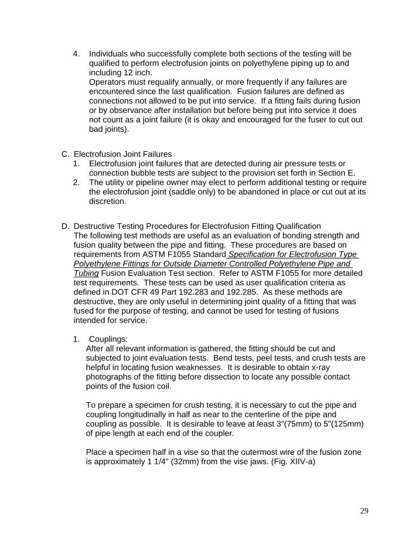
To prepare a specimen for crush testing, it is necessary to cut the pipe and coupling longitudinally in half as near to the centerline of the pipe and coupling as possible. It is desirable to leave at least 3"(75mm) to 5"(125mm) of pipe length at each end of the coupler. Place a specimen half in a vise so that the outermost wire of the fusion zone is approximately 1 1/4" (32mm) from the vise jaws. (Fig. XIIV-a)
30
Close the vise jaws until the pipe walls meet. (Fig. XIIV-b) Repeat this process for each end of both halves of the coupling. Inspect the crushed specimens for separation of the pipe and fitting in the fusion zone. Some minor separation (up to 15% measured as shown in the following examples) may be seen at the outermost region of the fusion zone, this does not constitute failure. Ductile failure of the pipe, fitting, or PE insulation around the wires is acceptable. There should be no separation at the fusion interface of the pipe and fitting. Passing (Fig. XIIV-c) and failing (Fig. XIIV-d) results are shown in the photographs.
Figure XIV-a Figure XIV-b
Figure XIV-c - Pass Figure XIV-d- Fail
Saddles/Tapping Tees 2.Tapping tees should be left intact for crush testing. Pipe lengths can be cut to the edges of the fitting base. Place the pipe and fitting into a vise (or suitable press) so that the jaws are within 1/2" (13mm) of the bottom of the saddle (Fig. XIV-e). Close the vise until the pipe walls meet (Fig. XIV-f). Inspect the crushed specimens for separation of the pipe and fitting in the fusion zone. Some minor separation (up to 15%) may be seen at the

31
outermost region of the fusion zone, this does not constitute failure. Ductile failure of the pipe, fitting, or PE insulation around the wires is acceptable. There should be no separation at the fusion interface of the pipe and fitting. Passing (Fig. XIV-g) and failing (Fig. XIV-h) results are shown in the photographs.
Figure XIV-e Figure XIV-f
Figure XIV-g – Pass Figure XIV-h - Fail
Further evaluations are possible by cutting the fusion area and surrounding pipe and fitting materials in thin longitudinal /cross sectional strips for bend tests. The strips are then placed into a vise and bent 90 degrees in both directions directly at the fusion interface and evaluated for separation. The same visual criteria are used for fusion evaluation tests as is used for crush tests (Fig. XIV-i).
Figure XIV-i
32
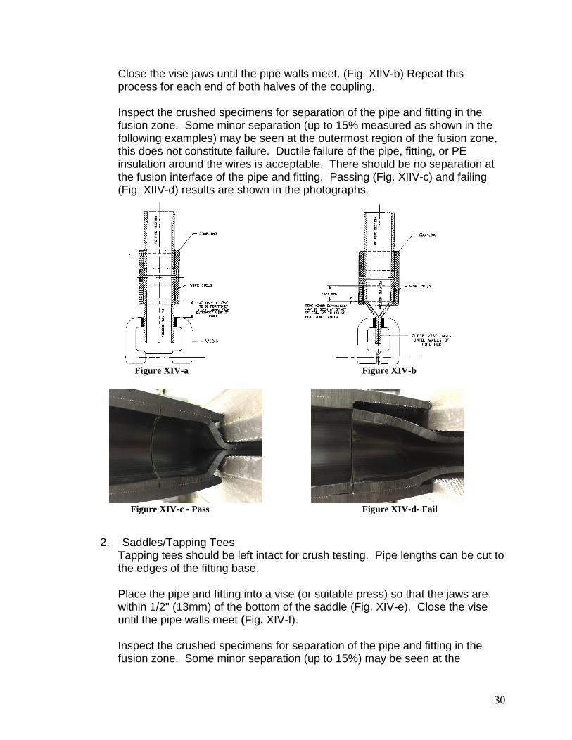
Couplings should have four longitudinal strips cut from the fusion interface at 90 intervals as shown (Fig. XIV-j). The strips should be approximately 1/16"(1.5mm) to 1/8"(3mm) in thickness. The strips are then placed into a vise and bent 90 degrees in both directions directly at the fusion interface and evaluated for separation.
Figure XIV-j
Tapping Tees should have strips cut along the center line of the pipe (Fig. XIV-k) through the fitting fusion surface and a strip cut from the radial side of each half of the fitting, totaling 4 strips for each sample fusion made. The strips are then placed into a vise and bent 90 degrees in both directions directly at the fusion interface and evaluated for separation.
Figure XIV-k
Required Re-Qualification and Retraining E.Failed electrofusion joints determined to be caused by improper installation procedures may warrant retraining and/or qualification of the installer. If an operator has failed electrofusion joint(s) under the provision previously listed or is observed using non specified or faulty equipment or not strictly adhering to all fusion procedures that operator will be disqualified from making additional electrofusion joints and will require additional training and requalification before performing any additional fusion joining.

33
Test Result and qualification test certificate F. The operator shall be presented with a completion certificate (or card) upon 1.
successful completion of the MAB Electrofusion Operator and Training & Qualification test valid for one year from date of issuance.
Successful Completion a. Operator cannot miss any questions on the written test. i.
Operator who misses two (2) questions or less can re-address a)the specific questions with the trainer and re-take written test in its entirety.
Operator who misses more than two (2) questions must re-take b)both the written and re-submit two (2) additional test specimens for destructive testing.
Operators must pass the destructive testing on all submitted ii.electrofusion joints.
Qualification Test Certificate 2. Certificate shall contain the following: a.
Operators Full Name i. Date, Place of Training ii. Date of Issue iii. Expiration Date of Test Certificate iv. Signature of Authorized Trainer v.
Failed electrofusion or written Test 3. Operator shall undergo further education and training prior to re-taking a.
the qualification test.

34
Appendix A – List of Electrofusion System Manufacturing Companies
The generic Electrofusion procedure has been endorsed by the following Electrofusion companies (listed alphabetically) for use with their Fittings. This list will be updated quarterly if needed.
1. Agru America (800) 373-2478 http://agruamerica.com
2. Georg Fischer Central Plastics (800) 654-3872 www.gfcp.com
3. Integrity Fusion Products (770) 632-7530 http://integrityfusion.com
4. IPEX Inc. (866) 473-9462 http://www.ipexinc.com/
5. M.T. Deason Company (800) 633-7131 http://mtdeason.com
6. Nupi Americas (281) 590-4471 www.nupiamericas.com
7. Plasson USA (800) 241-4175 www.plassonusa.com
8. Strongbridge-Tega (904) 278-7499 http://strongbridge.us/

35
Appendix B - Generic Electrofusion Operator Training & Qualification Section
DESTRUCTIVE TESTING
Operator Name:___________________ Date:_____________________ Location:________________ Electrofusion Coupling
Fitting Size:
Fitting Manufacturer:
Fitting Fusion Time:
Fitting Cooling Time:
PASS/FAIL:_______________________________ Electrofusion Saddle Fitting
Fitting Size:
Fitting Manufacturer:
Fitting Fusion Time:
Fitting Cooling Time:
PASS/FAIL:_______________________________ Authorized Trainer:________________________ Date:________________
Operator Training Card Card No. #xxx (Operator Name)_______________________________ has successfully completed the training requirements for qualifications to fuse Electrofusion Fittings according to (Utility Name) Department Standards with no restrictions. I have instructed and tested the above in all requirements and procedures related to installation of Electrofusion Fittings according to (Utility Name) Department Standards.
________________________________________________________________________________ Authorized Instructor Date Issued Expiration Date
Insert Photo

36
Appendix C – Sample Test
The following is a sample written qualification test.
Users should modify this test to address their unique operating environment.
Generic Electrofusion Operator Training & Qualification Section
Operator Name: ____________________ Date: _____________________
Location: ________________
All Questions should be answered with either T for True or F for False. The operator must
answer all questions correctly! 100% is the only passing grade.
1. The purpose of scraping is to remove the oxidized layer of PE pipe from the pipe
surface prior to electrofusion.
a. True
b. False
2. For out of round pipe it is acceptable to scrape the high points until the pipe fits into the
electrofusion coupling.
a. True
b. False
3. Sand paper, dragon skin, emory cloth, and other abrasives are acceptable for
scraping.
a. True
b. False
4. If the pipe becomes re-contaminated after scraping it is acceptable to use Isopropyl
Alcohol for cleaning purposes.
a. True
b. False
5. It is acceptable to perform an electrofusion with a slight trickle of water running across
the fusion area.
a. True
b. False
6. In case of an input power interruption only, an electrofusion fitting can be refused for
the entire fusion time after it has been allowed to cool completely.
a. True
b. False
7. Pressurizing, testing, and backfill can be performed immediately after the electrofusion
has been completed.
a. True
b. False
8. Pipe ends can be cut to within 10 of being completely square.
a. True
b. False
37
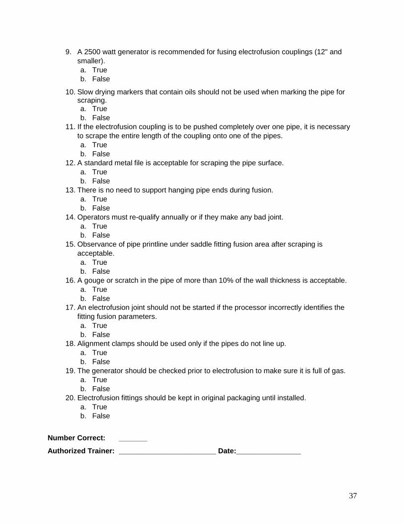
9. A 2500 watt generator is recommended for fusing electrofusion couplings (12" and
smaller).
a. True
b. False
10. Slow drying markers that contain oils should not be used when marking the pipe for scraping. a. True
b. False
11. If the electrofusion coupling is to be pushed completely over one pipe, it is necessary
to scrape the entire length of the coupling onto one of the pipes.
a. True
b. False
12. A standard metal file is acceptable for scraping the pipe surface.
a. True
b. False
13. There is no need to support hanging pipe ends during fusion.
a. True
b. False
14. Operators must re-qualify annually or if they make any bad joint.
a. True
b. False
15. Observance of pipe printline under saddle fitting fusion area after scraping is
acceptable.
a. True
b. False
16. A gouge or scratch in the pipe of more than 10% of the wall thickness is acceptable.
a. True
b. False
17. An electrofusion joint should not be started if the processor incorrectly identifies the
fitting fusion parameters.
a. True
b. False
18. Alignment clamps should be used only if the pipes do not line up.
a. True
b. False
19. The generator should be checked prior to electrofusion to make sure it is full of gas.
a. True
b. False
20. Electrofusion fittings should be kept in original packaging until installed.
a. True
b. False
Number Correct: _______
Authorized Trainer: ________________________ Date:________________