multistage magnetically coupled pumps - hermetic pumps · pdf fileas it is the case with...
TRANSCRIPT

Multistage magnetically coupled pumps
Model series MCAM
P R O D U C T I N F O R M A T I O N

General
Hermetically sealed pumps with magnetic coupling are char-
acterized by a single-acting safety sleeve. The separation of
liquid to the atmosphere is effected via the so-called con-
tainment shell. As it is the case with conventional centrifugal
pumps with mechanical seal, a common standard motor is
used which one is combined with the magnetic drive through
a coupling for the drive of the pump. The outer rotor contains
permanent magnets transferring the turning moment created
by the motor via the containment shell to the inner rotor.
Description
Description .......................................... 2
Application and insertion ..................... 4
Materials ............................................. 5
Functional principle ............................ 6
Monitoring systems .............................. 9
Characteristics diagramm ..................... 10
Contents
2
impellers discharge nozzle innerrotor
outerstator
drive shaft
suction nozzle slide bearing containment shell (safaty sleeve)
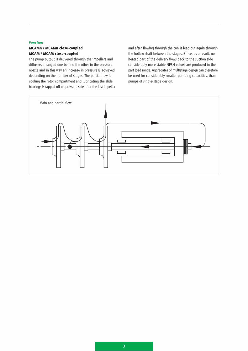
Function
MCAMn / MCAMn close-coupled
MCAM / MCAM close-coupled
The pump output is delivered through the impellers and
diffusers arranged one behind the other to the pressure
nozzle and in this way an increase in pressure is achieved
depending on the number of stages. The partial flow for
cooling the rotor compartment and lubricating the slide
bearings is tapped off on pressure side after the last impeller
3
and after flowing through the can is lead out again through
the hollow shaft between the stages. Since, as a result, no
heated part of the delivery flows back to the suction side
considerably more stable NPSH values are produced in the
part load range. Aggregates of multistage design can therefore
be used for considerably smaller pumping capacities, than
pumps of single-stage design.
Main and partial flow
Design
The constructional features of these pumps correspond to those
of a multistage pump and consist of a permanent magnetic
coupling as an integral part. The required output is trans-
ferred to the pump via a conventional standard three phase
current motor of type B 3 or B 35 with the corresponding
intermediate coupling.
Application sector
For the delivery of aggressive, toxic, explosive, precious,
inflammable and slightly volatile fuids.
Application ranges
MCAMn: –40 °C to +220 °C *
MCAM: –40 °C to +220 °C *
MCAMn close-coupled: –40 °C to +100 °C **
MCAM close-coupled: –40 °C to +100 °C **
** ≥ 220 °C on request
** ≥ 100 °C on request
Magnetic drive
Thanks to the use of new types of permanent magnetic
materials with high energy density, it is possible to house
a powerful magnetic coupling within the pump bearing
support specified in the standard. The magnetic drive is
equipped for direct activation when operated using standard
three phase current motors and does not require any type
of coupling. In addition, the permanent magnets are highly
stable against demagnetising effects, such as those which
may occur when assembling or disassembling the rotor or
if the maximum transmittable torque is exceeded.
Power ■■ up to 24 kW at 1450 rpm ■■ up to 58 kW at 2900 rpm
(larger ratings are possible on demand)
Explosion protection
according to EC design test certificate in line with Directive
94/9/EC (ATEX) II 2 G c IIC T2 to T6
Documentation according to HERMETIC-Standard ■■ operating instructions incl. instructions for
commissioning, operation and maintenance■■ technical specification■■ sectional drawing with position numbers■■ dimensional drawing■■ spare part list with order numbers■■ test certificate■■ test performance curve■■ EC Declaration of Conformity
Inspections and guarantees
Standard inspections
Hydraulic inspection: ■■ each pump is subject to a test run and the operating
point is guaranteed according to ISO 9906 – class 2B
(5 measuring points) ■■ pressure test ■■ leak test ■■ balancing the shaft and impellers according to
DIN/ISO 1940, 6.3
Additional inspections
The following inspections can be carried out and certified
against additional price (e.g. NPSH test, Helium leakage test,
vibration test, ultrasonic test, PMI test). Any further inspec-
tions and tests are according to the technical specification.
The guarantees are effected according to the valid conditions
of supply.
Application and insertion
4
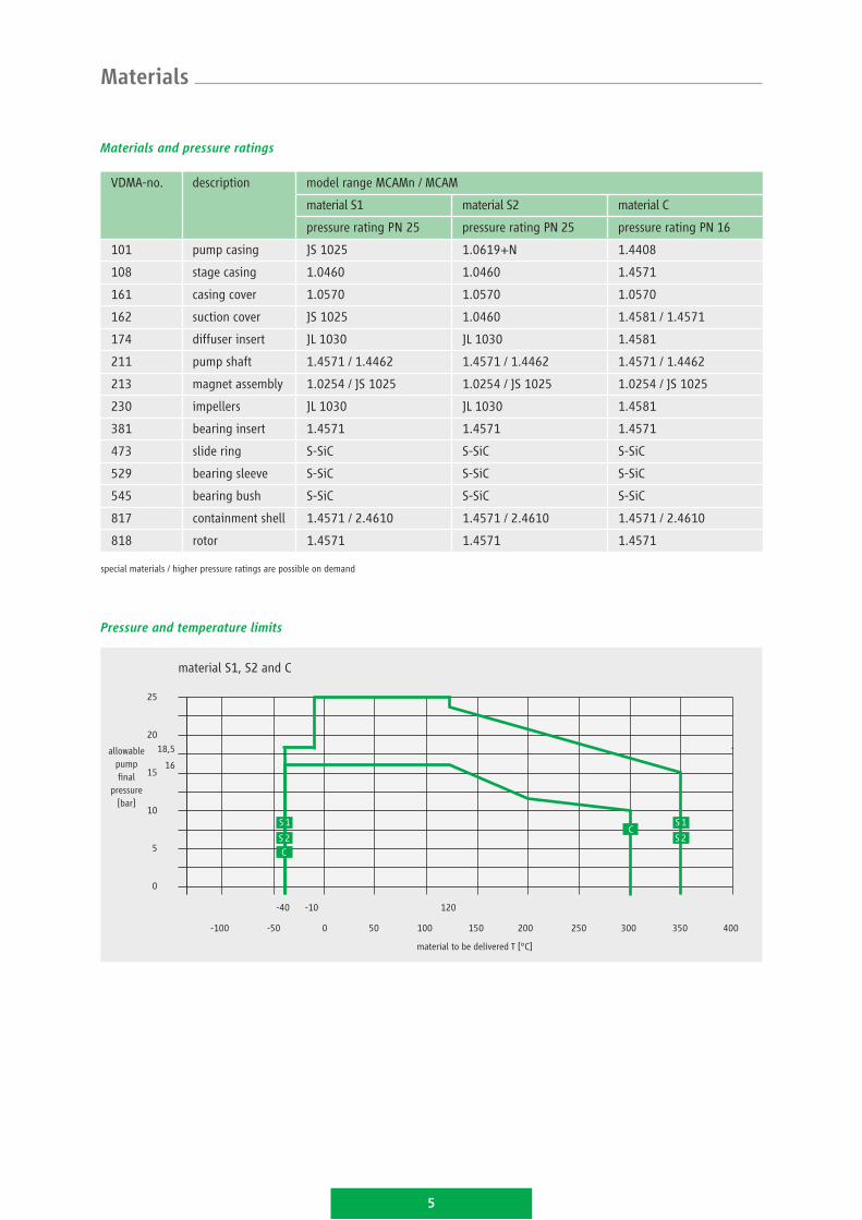
Materials and pressure ratings
VDMA-no. description model range MCAMn / MCAM
material S1 material S2 material C
pressure rating PN 25 pressure rating PN 25 pressure rating PN 16
101 pump casing JS 1025 1.0619+N 1.4408
108 stage casing 1.0460 1.0460 1.4571
161 casing cover 1.0570 1.0570 1.0570
162 suction cover JS 1025 1.0460 1.4581 / 1.4571
174 diffuser insert JL 1030 JL 1030 1.4581
211 pump shaft 1.4571 / 1.4462 1.4571 / 1.4462 1.4571 / 1.4462
213 magnet assembly 1.0254 / JS 1025 1.0254 / JS 1025 1.0254 / JS 1025
230 impellers JL 1030 JL 1030 1.4581
381 bearing insert 1.4571 1.4571 1.4571
473 slide ring S-SiC S-SiC S-SiC
529 bearing sleeve S-SiC S-SiC S-SiC
545 bearing bush S-SiC S-SiC S-SiC
817 containment shell 1.4571 / 2.4610 1.4571 / 2.4610 1.4571 / 2.4610
818 rotor 1.4571 1.4571 1.4571
special materials / higher pressure ratings are possible on demand
Materials
Pressure and temperature limits
16
-40 120
material S1, S2 and C
material to be delivered T [°C]
-10
18,5
25
20
10
5
0
15
-100 0 50 100 150 200 250 300 400350-50
C
S 1
S 2
5
C S 1
S 2
allowablepump final
pressure[bar]

Magnetically coupled pump in bearing bracket design
Magnetically coupled pump in close-coupled design
Functional principle
6
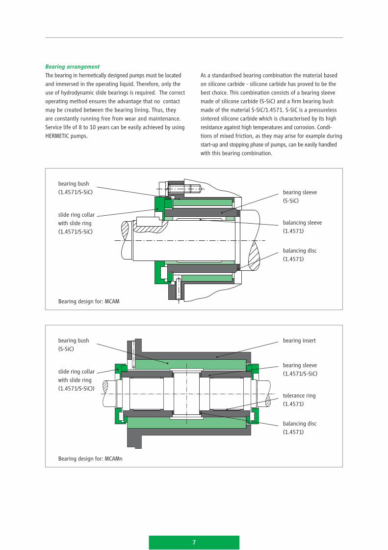
slide ring collarwith slide ring(1.4571/S-SiC)
bearing sleeve(S-SiC)
balancing disc(1.4571)
bearing bush(1.4571/S-SiC)
7
Bearing arrangement
The bearing in hermetically designed pumps must be located
and immersed in the operating liquid. Therefore, only the
use of hydrodynamic slide bearings is required. The correct
operating method ensures the advantage that no contact
may be created between the bearing lining. Thus, they
are constantly running free from wear and maintenance.
Service life of 8 to 10 years can be easily achieved by using
HERMETIC pumps.
As a standardised bearing combination the material based
on silicone carbide - silicone carbide has proved to be the
best choice. This combination consists of a bearing sleeve
made of silicone carbide (S-SiC) and a firm bearing bush
made of the material S-SiC/1.4571. S-SiC is a pressureless
sintered silicone carbide which is characterised by its high
resistance against high temperatures and corrosion. Condi-
tions of mixed friction, as they may arise for example during
start-up and stopping phase of pumps, can be easily handled
with this bearing combination.
balancing sleeve(1.4571)
slide ring collarwith slide ring(1.4571/S-SiC))
bearing sleeve(1.4571/S-SiC)
balancing disc(1.4571)
bearing bush(S-SiC)
tolerance ring(1.4571)
bearing insert
Bearing design for: MCAM
Bearing design for: MCAMn
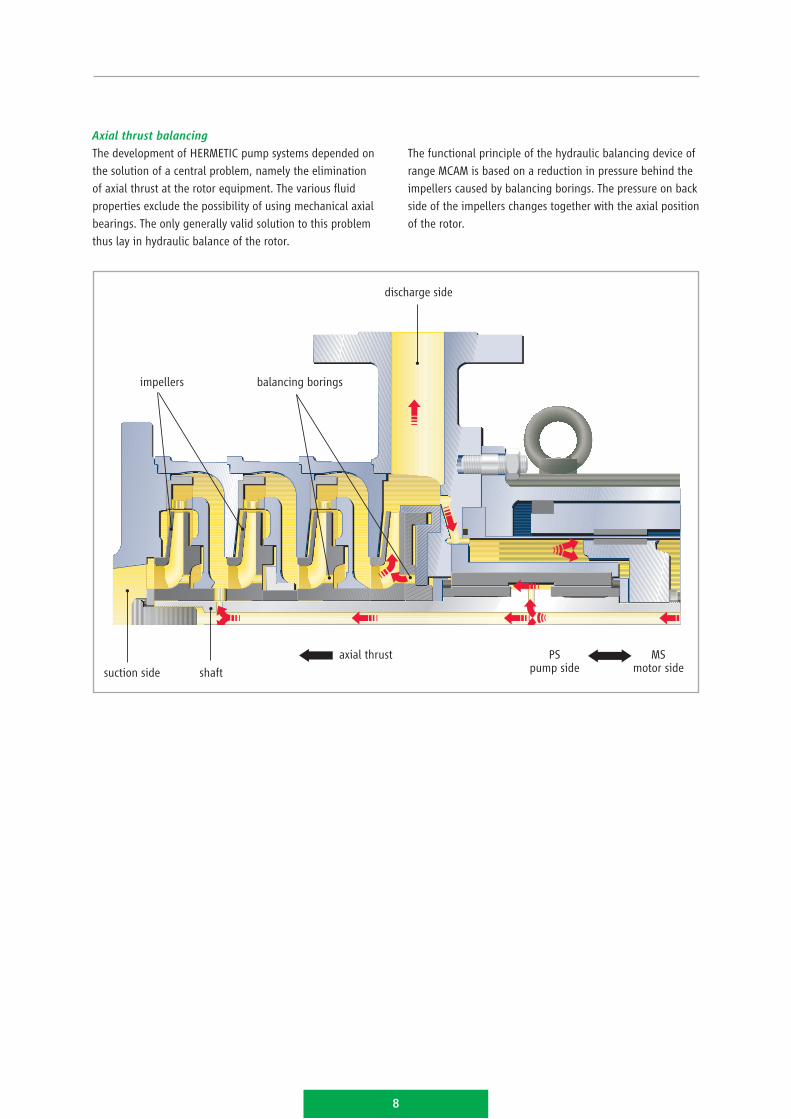
Axial thrust balancing
The development of HERMETIC pump systems depended on
the solution of a central problem, namely the elimination
of axial thrust at the rotor equipment. The various fluid
properties exclude the possibility of using mechanical axial
bearings. The only generally valid solution to this problem
thus lay in hydraulic balance of the rotor.
The functional principle of the hydraulic balancing device of
range MCAM is based on a reduction in pressure behind the
impellers caused by balancing borings. The pressure on back
side of the impellers changes together with the axial position
of the rotor.
8
Axialschubentlastung
Die Entwicklung hermetischer Pumpen war von der Lösung
eines zentralen Problems, dem der Eliminierung axialer
Kräfte am Läufer, abhängig. Die breite Palette der Stoffeigen-
schaften der zu fördernden Fluide schließt die Verwendung
mechanischer Axiallager aus. Allgemein gültig konnte diese
Aufgabe nur durch die hydraulische Entlastung des Läufers
gelöst werden.
Das Funktionsprinzip der hydraulischen Entlastungseinrich-
tung der Baureihe MCAM beruht auf der Druckminderung
hinter den Laufrädern bedingt durch Entlastungsbohrungen.
Der Druck auf der Rückseite der Laufräder verändert sich mit
der axialen Position des Läufers.
8
discharge side
balancing boringsimpellers
suction side shaft
axial thrust PS pump side
MS motor side

Monitoring systems
9
The most part of HERMETIC pumps are designed according
to explosion protection requirements. The pumps comply
with the requirements of the electrical as well as mechanical
explosion protection.
Level monitoring
On condition that the rotor cavity as part of the process
system is steadily filled with liquid, no explosive atmosphere
may arise. In this case, no accepted explosion protection is
required for the rotor cavity. If the operator is not able to
guarantee for a steady filling, it is necessary to install level
monitoring devices.
Temperature monitoring
The observance of the temperature class and the maximum
admissible surface temperature is ensured by a measuring
point on the containment shell (liquid temperature).
various monitoring devices
1 Type N 30 LSlevel
2 Type O 30 LS
3 Type PT 100 TI temperature
1
2
3
6
7

10
Characteristics diagram
Characteristics diagram 3000 rpm 50 Hz
1 MCAM 2 / 2- 6 stages
2 MCAM 3 / 2- 6 stages
Denomination of hydraulics to the characteristics diagram
US.gpm
H[m]
10
10 501
10
100
100
200100
Q[m3/h]
H[ft]
3
1
2
1

11
Characteristics diagram 3600 rpm 60 Hz
1 MCAM 2 / 2- 6 stages
2 MCAM 3 / 2- 6 stages
Denomination of hydraulics to the characteristics diagram
US.gpm
Q[m3/h]
H[m]
H[ft]
10
100
100
1000
200
10
1
100
100
2
1
Among others, our products comply with:■■ Directive 2006/42/EC
(Machinery Directive)■■ Explosion protection acc. to
Directive 94/9/EC (ATEX); UL; KOSHA;
NEPSI; CQST; CSA; Rostechnadzor■■ Directive 96/61/EC (IPPC Directive)■■ Directive 1999/13/EC (VOC Directive)■■ TA-Luft■■ RCC-M, Niveau 1, 2, 3
HERMETIC-Pumpen GmbH is certified acc. to:■■ ISO 9001:2008■■ GOST; GOST “R”■■ Directive 94/9/EC■■ AD 2000 HP 0; Directive 97/23/EC■■ DIN EN ISO 3834-2■■ KTA 1401; AVS D 100 / 50;
IAEA 50-C-Q■■ Certified company acc. to § 19 I WH
Important features are readiness, mobility, flexibility, availability and reliability.
We are anxious to ensure a pump operation at best availability and efficiency
to our customers.
Convincing service.
Installation and commissioning■ service effected on site by own
service technicians
Spare part servicing■ prompt and longstanding
availability■ customized assistance in spare
part stockkeeping
Repair and overhauling■ professional repairs including test
run executed by the parent factory■ or executed by one of our service
stations worldwide
Retrofit■ retrofit of your centrifugal pumps
by installing a canned motor
to comply with the requirements
of the IPPC Directive
Maintenance and service
agreement■ concepts individually worked
out to increase the availability
of your production facilities
Training and workshops■ extra qualification of your
staff to ensure the course of
your manufacture
PRODUKTINFOMCAM/E/03/2016
All details as stated in this document comply with the technical standard that is applicable at the date of printing. These details are subject to technical innovations and modifications at any time.
HERMETIC-Pumpen GmbHGewerbestrasse 51 · D-79194 Gundelfingenphone +49 761 5830-0 · fax +49 761 [email protected]