multisensory five-finger dexterous hand: the dlr/hit hand ii
TRANSCRIPT

Fig.1 Comparison of the DLR/HIT HAND I and II(right)
Abstract—This paper presents a new developed multisensory five-fingered dexterous robot hand : the DLR/HIT Hand II. The hand has an independent palm and five identical modular fingers, each finger has three DOFs and four joints. All the actuators and electronics are integrated in the finger body and the palm. By using powerful super flat brushless DC motors, tiny harmonic drivers and BGA form DSPs and FPGAs, the whole finger’s size is about one third smaller than the former finger in the DLR/HIT Hand I. By using the steel coupling mechanism, the phalanx distal’s transmission ratio is exact 1:1 in the whole movement range. At the same time, the multisensory dexterous hand integrates position, force/torque and temperature sensors. The hierarchical hardware structure of the hand consists of the finger DSPs, the finger FPGAs, the palm FPGA and the PCI based DSP/FPGA board. The hand can communicate with external with PPSeCo , CAN and Internet. Instead of extra cover, the packing mechanism of the hand is implemented directly in the finger body and palm to make the hand smaller and more human like. The whole weight of the hand is about 1.5Kg and the fingertip force can reach 10N.
I. INTRODUCTION HE dexterous robot hands play an ever important role in the service robots and other challenge areas. Some nice
robot hands have been built in the labs and companies, such as the NASA Robonaut Hand[1], the Shadow Hand[2], the DLR Hand II[3] and the DLR/HIT Hand I [4]. Generally there are two kinds of hand, one is external actuation hand, where all the actuators are mounted in the forearm (NASA and Shadow), and another internal actuation hand(DLR, HIT), where there needs not any forearm and all the actuators and electronics are integrated in the finger body and the palm. Normally the internal actuation hand body is bigger than the external actuation hand. It is obvious that the internal actuation robot hand will have great perspective if it can be built smaller.
DLR and HIT have jointly developed a modular internal actuation DLR/HIT Hand I in 2004. It has four fingers with in total thirteen DOFs (Degree of Freedom) and each finger has three DOFs and four joints, last two joints are mechanically coupled by a rigid linkage. To achieve a high degree of modularity, all four fingers are identical. Instead of expensive VME bus board a PCI-based DSP/FPGA board has been successfully developed. Through a nice envelop design the hand looks much like a human shape. The packing of the DLR/HIT Hand I is realized by an extra plastic parts mounted on the finger bodies and palm. It needs more space and makes
This work was partially supported by National High Technology Research
and Development Program of China(863 Program), Grant #2006AA04Z255
the hand relative big. The whole size of the hand is about one and half of adult human hand. In 2006 the hand called also SAH( Schunk Anthropomorphic Hand)[5] has been distributed by SCHUNK. It has been successfully used in some universities and institutes [6] worldwide.
There are always increasing demands for a smaller internal actuation robot hand and the best with five fingers. To this aim the DLR and HIT have been jointly developing a new generation five-fingered robot hand since 2005. To make the hand smaller and with appropriate fingertip force (e.g. 10N) is not only dependent on novel mechanical design, but also on key elements, such as powerful actuators, tiny gears, novel sensors and miniature electronics. In the last years, there are great advance in the super flat BLDC motors, harmonic drivers and especially in the electronics, where the packages of more powerful processors and MOSFETs go smaller and smaller, such as BGA(Ball Grid Array). On this background DLR and HIT started a new round modular hand design and successfully built a new generation modular internal actuation robot hand. This paper is organized as: Section II presents an overview of the DLR/HIT Hand II; Section III describes the modular internal actuation finger; Section IV and V will give a deep insight on the multisensory system of the hand and envelop design of the hand; Section VI and VII will present the hardware and software architecture respectively; Conclusions and future work are addressed in section VIII.
II. OVERVIEW OF THE DLR-HIT-HAND II The DLR-HIT-Hand II is a multisensory and integrated five-fingered hand with in total fifteen DOFs, as shown in the
H. Liu, K. Wu, P. Meusel, N. Seitz, G. Hirzinger M.H. Jin, Y.W. Liu, S.W.Fan, T. Lan, Z.P.Chen Institute of Robotics and Mechatronics Robot Research Institute German Aerospace Center, DLR Harbin Institute of Technology, HIT 82230 Wessling Germany 150001 Harbin P.R.China
Multisensory Five-Finger Dexterous Hand: The DLR/HIT Hand II
T
2008 IEEE/RSJ International Conference on Intelligent Robots and SystemsAcropolis Convention CenterNice, France, Sept, 22-26, 2008
978-1-4244-2058-2/08/$25.00 ©2008 IEEE. 3692
right of Fig.1. To achieve a high degree of modularity, all five fingers are identical. Each finger has three DOFs and four joints, last two joints are mechanically coupled. All actuators, gears, the electronics and communication controllers for one finger are fully integrated in the finger’s base or the finger’s body directly.
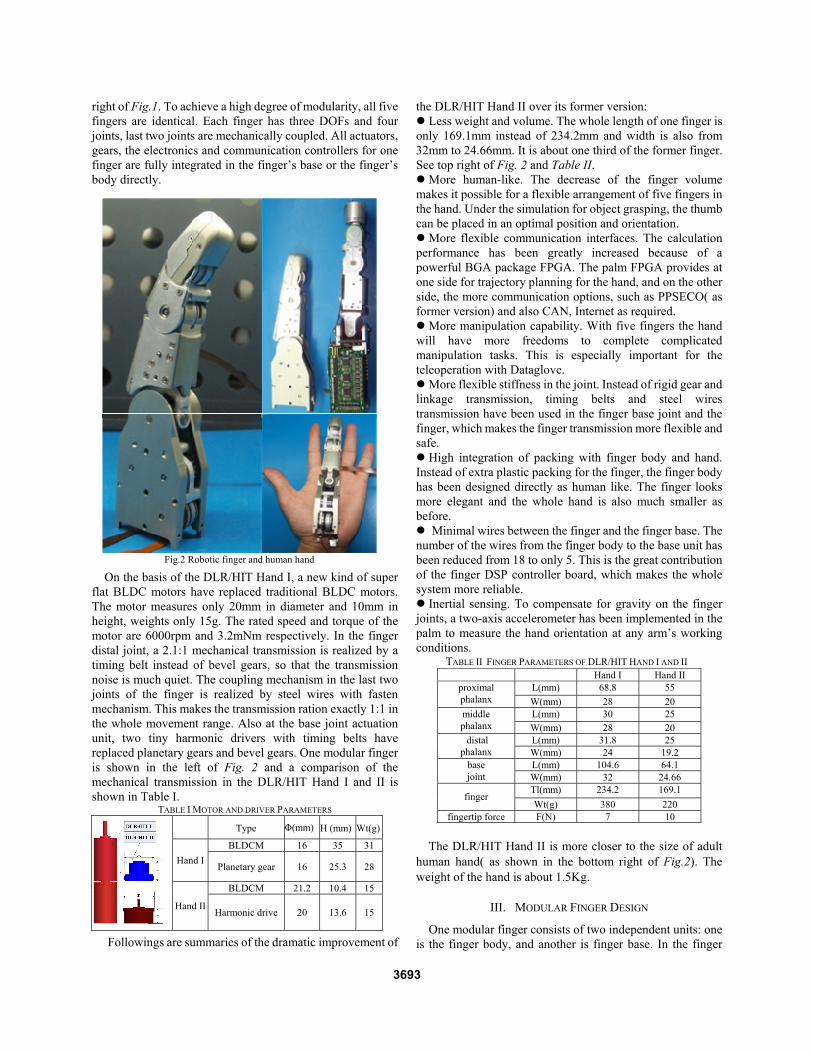
On the basis of the DLR/HIT Hand I, a new kind of super flat BLDC motors have replaced traditional BLDC motors. The motor measures only 20mm in diameter and 10mm in height, weights only 15g. The rated speed and torque of the motor are 6000rpm and 3.2mNm respectively. In the finger distal joint, a 2.1:1 mechanical transmission is realized by a timing belt instead of bevel gears, so that the transmission noise is much quiet. The coupling mechanism in the last two joints of the finger is realized by steel wires with fasten mechanism. This makes the transmission ration exactly 1:1 in the whole movement range. Also at the base joint actuation unit, two tiny harmonic drivers with timing belts have replaced planetary gears and bevel gears. One modular finger is shown in the left of Fig. 2 and a comparison of the mechanical transmission in the DLR/HIT Hand I and II is shown in Table I.
TABLE I MOTOR AND DRIVER PARAMETERS
Followings are summaries of the dramatic improvement of
the DLR/HIT Hand II over its former version: Less weight and volume. The whole length of one finger is
only 169.1mm instead of 234.2mm and width is also from 32mm to 24.66mm. It is about one third of the former finger. See top right of Fig. 2 and Table II.
More human-like. The decrease of the finger volume makes it possible for a flexible arrangement of five fingers in the hand. Under the simulation for object grasping, the thumb can be placed in an optimal position and orientation.
More flexible communication interfaces. The calculation performance has been greatly increased because of a powerful BGA package FPGA. The palm FPGA provides at one side for trajectory planning for the hand, and on the other side, the more communication options, such as PPSECO( as former version) and also CAN, Internet as required.
More manipulation capability. With five fingers the hand will have more freedoms to complete complicated manipulation tasks. This is especially important for the teleoperation with Dataglove.
More flexible stiffness in the joint. Instead of rigid gear and linkage transmission, timing belts and steel wires transmission have been used in the finger base joint and the finger, which makes the finger transmission more flexible and safe.
High integration of packing with finger body and hand. Instead of extra plastic packing for the finger, the finger body has been designed directly as human like. The finger looks more elegant and the whole hand is also much smaller as before.
Minimal wires between the finger and the finger base. The number of the wires from the finger body to the base unit has been reduced from 18 to only 5. This is the great contribution of the finger DSP controller board, which makes the whole system more reliable.
Inertial sensing. To compensate for gravity on the finger joints, a two-axis accelerometer has been implemented in the palm to measure the hand orientation at any arm’s working conditions.
TABLE II FINGER PARAMETERS OF DLR/HIT HAND I AND II Hand I Hand II
L(mm) 68.8 55 proximal phalanx W(mm) 28 20
L(mm) 30 25 middle phalanx W(mm) 28 20
L(mm) 31.8 25 distal phalanx W(mm) 24 19.2
L(mm) 104.6 64.1 base joint W(mm) 32 24.66
Tl(mm) 234.2 169.1 finger
Wt(g) 380 220 fingertip force F(N) 7 10
The DLR/HIT Hand II is more closer to the size of adult
human hand( as shown in the bottom right of Fig.2). The weight of the hand is about 1.5Kg.
III. MODULAR FINGER DESIGN
One modular finger consists of two independent units: one is the finger body, and another is finger base. In the finger
Type Φ(mm) H (mm) Wt(g)
BLDCM 16 35 31 Hand I Planetary gear 16 25.3 28
BLDCM 21.2 10.4 15
Hand II Harmonic drive 20 13.6 15
Fig.2 Robotic finger and human hand
3693
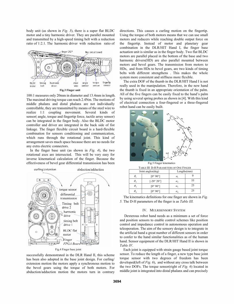
TABLE III D-H PARAMETERS OF ONE FINGER Joint angles(deg) Lengths(mm)
1θ [0° 90°] 1a 0
2θ [-20° 20°] 2a 55
3θ [0° 90°] 3a 25
4θ [0° 90°] 4a 25
body unit (as shown in Fig. 3), there is a super flat BLDC motor and a tiny harmonic driver. They are parallel mounted and transmitted by a high-speed timing belt with a reduction ratio of 1:2.1. The harmonic driver with reduction ratio of
100:1 measures only 20mm in diameter and 13.4mm in length. The maximal driving torque can reach 2.4Nm. The motions of middle phalanx and distal phalanx are not individually controllable, they are transmitted by means of the steel wire to realize 1:1 coupling movement. Several kinds of sensor( angle, torque and fingertip force, tactile array sensor) can be integrated in the finger body. Also the BLDC motor controller and driver are integrated in the back side of fist linkage. The finger flexible circuit board is a hard-flexible combination for sensors conditioning and communication, which runs through the rotational joint. This kind of arrangement saves much space because there are no needs for any extra electric connectors.
In the finger base unit (as shown in Fig. 4), the two rotational axes are intersected. This will be very easy for inverse kinematical calculation of the finger. Because the effectiveness of bevel gear differential transmission has been
successfully demonstrated in the DLR Hand II, this scheme has been also adopted in the base joint design. For curling/ extension motion the motors apply a synchronous motion to the bevel gears using the torque of both motors. For abduction/adduction motion the motors turn in contrary
directions. This causes a curling motion on the fingertip. Using the torque of both motors means that we can use small motors and reducers while reaching double output force on the fingertip. Instead of motor and planetary gear combination in the DLR/HIT Hand I, the finger base actuation unit is similar as in the finger body. Two flat BLDC motors are parallel placed in the bottom of the base and two harmonic drivers(HD) are also parallel mounted between motors and bevel gears. The transmission from motors to HDs, and from HDs to bevel gears, are two kinds of timing belts with different strengthens . This makes the whole system more consistent and stiffness more flexible.
The extra DOF of the thumb in the DLR/HIT Hand I is not really used in the manipulation. Therefore, in the new hand the thumb is fixed in an appropriate orientation of the palm. All of the five fingers can be easily fixed to the hand’s palm by using several spring probes as shown in [4]. With this kind of electrical connection a four-fingered or a three-fingered robot hand can be easily built.
The kinematics definitions for one finger are shown in Fig. 5. The D-H parameters of the finger is as Table III.
IV. MULRISENSORY SYSTEM Dexterous robot hand needs as a minimum a set of force and position sensors to enable control schemes like position control and impedance control in autonomous operation and teleoperation. The aim of the sensory design is to integrate in the artificial hand a great number of different sensors in order to confer to the hand similar functionalities as of the human hand. Sensor equipment of the DLR/HIT Hand II is shown in Table IV.
Each joint is equipped with strain gauge based joint torque sensor. To reduce the length of a finger, a new type base joint torque sensor with two degrees of freedom has been developed(left of Fig. 6), and without any cross talk between the two DOFs. The torque sensor(right of Fig. 6) located in middle joint is integrated into distal phalanx and can precisely
Fig.3 Finger unit
Fig.4 Finger base joint
Fig.5 Finger kinematics
3694

Fig. 9 Packing house of a finger and the palm(bottom)
measure the external torque without hysteresis. Two special designed potentiometers(left of Fig.7) in the
base joint and a contactless magnetic angle sensor(right of Fig. 7) in the finger unit are adopted as joint absolute angel
sensors. Each finger is equipped with a tiny six dimensional sensor (20mm in diameter and 16mm in height (Fig. 8) with full digital output has been developed for the fingertip. The elastic body is made from only one part and all strain gauges are on one surface (right of Fig. 8), rendering the sensor extremely flat and very appropriate for thin film technology of strain gauges for easier assembly. A signal processing circuit and high speed serial A/D converter (12bit) are also integrated in the sensor.
In addition, a piezo-resistive tactile sensor array is under development. With this sensor the contact area can be calculated exactly.
V. ENVELOP DESIGN OF THE HAND Hand envelop design is very important for the appearance
of the hand and also for optimal grasping and protection of the hand. In the DLR/HIT Hand I, we implement a nice cover for the hand with an extra plastic parts just as shown in the left of the Fig. 1. With this solution the hand will be bigger than it’s functional body. In order to make the hand smaller, we are
trying to design the finger body directly as human like. Fig.9 shows the main complicated parts of the hand. The parts on the top of the figure are the back part of the first linkage and the fingertip. The three big parts at the bottom of the Fig. 9 will build a complete human-like palm as shown in the Fig. 1.
VI. HARDWARE ARCHITECTURE
The hardware architecture consists of a PCI-based central
floating point DSP/FPGA processor for hand control; a palm FPGA controller for local processing and data communication; finger base FPGAs for 2 DOFs base joint motor control and a miniature DSP for the finger joint motor control. The Fig. 10 shows the components in one hand, where finger DSP and base FPGA are integrated in the finger body and finger base. The finger DSP communicates with palm FPGA through a high speed(6MBaud) half-duplex SCI interface. The palm FPGA controller can be divided into two parts: one is for sensor data and command communication with five fingers separately and also with external device with
Fig.6 Finger joint torque sensors
Fig.7 Finger joint position sensors
Fig.8 6 DOFs fingertip sensor and it’s structure
Fig.10 DLR-HIT-hand II hardware components
TABLE IV SENSOR REQUIREMENT OF ONE FINGER Sensor Type Count/finger Joint torque 3
Joint position 3 Motor position 3 Force/torque 1 Temperature 2
3695

CAN, Internet and PPSeCo to PCI-based DSP board, and another is for simple trajectory planning for the whole hand. Therefore, the hand can be a true stand-alone system. The main task of the PCI-based DSP/FPGA board is for high level grasping planning, optimization grip and communicates with palm through PPSeCo(Point to Point High Speed Serial Communication). The structure of three lays FPAG, including finger base FPGA, palm FPGA and FPGA on PCI board, realizes high speed real time communication based on PPSeCo with 25Mbps and needs only two wires.
A. Finger DSP Finger DSP(as shown in Fig. 11) is located in the back side of the first linkage of the finger. It completes the sensor signals processing, BLDC motor control and communication between the finger and the finger base. The DSP is a high performance TMS32028x™, which is a up to 100 MIPS 32-bit processor and has on-chip ADs, flash memory and offers up to 16 channels high resolution PWM with 150 ps(pico-second) resolution. It has also SPI and SCI interfaces, where SPI is for the extra sensor signals communication with serial AD converters, and SCI is for half-duplex high speed (6Mbps) data exchange between finger and Finger FPGA. Based on the finger DSP, the number of wires between the finger base and the finger has been reduced from 18( in DLR/HIT Hand I) to 5( 2 power supplies, 2 half-duplex and 1 common ground) . Because the wires should run through two DOFs of the base joint and the wires can be easily broken, less wires means a great increase of the whole system reliability.
B. Finger FPGA Finger FPGA(as shown in Fig. 12) is located in the
bottom of a finger base. It realizes the sensor signal sampling and calibration, two BLDC motors control and communication with the finger DSP and also palm FPGA. The finger FPGA EP2C20FX is from Altera. It has sufficient digital interfaces and on-chip embedded NIOS processor. It reads the digital Hall signals from BLDC motors and processes the phase commutation to control the driver gates of MOSFETs directly. The motors driving has an extra current protection function. The sensor calibration and limit angle protection of the joints are also implemented in the finger FPGA by NIOS soft core
embedded processor.
C. Palm FPGA Compared with the palm FPGA board in the DLR/HIT
Hand I, a more powerful Cyclone II FPGA has been implemented. It has more on-chip resources and hardware floating point calculation with 250 DMIPS. A double NIOS kernel system has been realized in the palm FPGA, one is for the communication block between the palm and finger FPGA and also between palm and the central PCI based DSP/FPGA board. Also this block provides further communication interfaces such as CAN and Internet. Another block is for more powerful calculation for normal trajectory planning and control algorithm. Therefore, the hand can be a whole stand-alone system. This is a great jump compared with the former version.
Both blocks share a on-chip RAM for data exchange. If more complicated control algorithm has to be implemented, the communication block can also provide PPSeCo with a baud rate up to25Mbps to transmit data and command with
PCI based DSP board in a normal PC. The palm FPGA board(as shown in Fig. 13) performs data
transmission between the finger FPGA and the PCI based DSP/FPGA board via PPSeCo communication system. The command signals received from the DSP/FPGA PCI board are firstly stored in buffer of the palm FPGA and then distributed to each finger FPGA. In other ways, the sensor information received from the finger FPGA is also stored in
Fig.12 The Structure of finger FPGA
Fig.13 The Structure of palm FPGA
Fig.11 The Structure of finger DSP
3696

Fig.15 The DLR/HIT Hand II mounted on the DLR’s JUSTIN
the buffer of the PCI board first, then the palm FPGA packs them to data package in some way and transmits it to the PCI based DSP/FPGA board. The palm FPGA reads the information from the five finger FPGA boards through synchronization approach with system clock. The palm FPGA provides maximal six PPSeCo ports, one is for the PCI board, five ports are for the five finger-FPGA boards.
Furthermore, DC/DC converter based power supply for all fingers is also integrated in the palm FPGA board. It provides power for all analog circuitry, including the finger FPGA boards, the BLDC motor driving boards and all sensor signals processing boards.
D. PCI based DSP/FPGA board The main controller of the DLR/HIT Hand II is a TI floating
point digital signal processor(DSP) TMS320C6713 with maximum 1350 MFLOPS. According to the high performance and unique hardware structure of the DSP, it’s an optimal alternative to realize complex control algorithm and very fast computation easily.
Based on the DSP chip, a PCI based DSP/FPGA board was designed (as shown in the bottom left of Fig.10). The PCI board exchanges data with PC via PCI bridge controller. At the same time, the board communicates with the palm FPGA via PPSeCo achieved absolutely by the way of hardware. On the PCI board, DSP and FPGA achieve data exchange via a fast parallel interface. All high level data processing is implemented on the DSP board, the DSP mainly plays as a computing unit for complex control algorithm because of its high performance floating-point capabilities. And the FPGA communicates with external components from the PCI board via serial interface. The FPGA converts serial signals from the palm FPGA to parallel signals and transmits them to the DSP via the parallel interface, and vice versa.
Further more, the PCI based DSP/FPGA board communicates with PC via 33MHz PCI bus and provides two PPSeCo interfaces for two independent palm FPGA communication controllers to control two hands simultaneously or control one hand and one robot arm.
VII. SOFTWARE ARCHITECTURE Based on the hardware structure of the DLR-HIT-Hand,
the software architecture has been developed according to principle of multi-level structure and modularity. As shown in Fig. 14,all data processing and control algorithm of the hand are realized in five levels. In Lower Control Level, sensor data acquisition and motor actuation are implemented by finger DSP board and FPGA board. The Data Process Level performs all data processing and communication needed to pack all digital sensor values from Lower Control Level and distribute command signals to each finger. The Higher Control Level implements all computation for the hand and provides basic client interface for External Command Level, such as PC and data glove. The control cycle for the hand is about 200us.
VIII. CONCLUSIONS AND FUTURE WORK The paper presents a high performance hardware and
software architecture of the DLR/HIT Hand II. With this basic architecture, many control arithmetic for the hand such as position control and impedance control, and demo moving program have been successfully realized. The future work will be concentrated on the control, grasping and tele-operation experiments. The Fig. 15 shows the DLR/HIT Hand II mounted on the DLR humanoid robot JUSTIN.
REFERENCES [1] C.S.Lovchik, M.A.Difler, “The Robonaut Hand: A Dextrous Robotic
Hand for Space,” Proceedings of the IEEE International Conference on Robotics and Automation. Detroit, Michigan. 1999:907-912
[2] http://www.shadowrobot.com/hand/ [3] J. Butterfass, M. Grebenstein, H. Liu, "DLR-Hand II: Next generation
of a dexterous robot hand," In Proceedings of the 2001 IEEE International conference on Robotics & Automation. 2001, pp. 109-114
[4] H. Liu, P. Meusel, N. Seitz etc. “The modular multisensory DLR-HIT-Hand“, proc. Of Elsevier Int. conf. Mechanism and Machine Theory, pp.1-14. 2006
[5] http://www.schunk-usa.com/schunk/schunk_websites/news/subject_of_the_month.html?article_id=9340&country=USA&lngCode=EN&lngCode2=EN
[6] Z. Xue, M. Zoellner and R. Dillmann.”Grasp Planning: Find The Contact Points”, Proceeding, IEEE International Conference on Robotics and Biomimetics (Robio2007), December 2007
Fig.14 Software architecture of DLR-HIT-HAND II
3697