multiscale approach for modeling fracture …imim.pl/files/archiwum/vol1_2018/03.pdf · multiscale...
TRANSCRIPT

Arch. Metall. Mater. 63 (2018), 1, 19-28
DOI: 10.24425/118903
M. BIGLAR*, F. STACHOWICZ*, T. TRZEPIECIŃSKI*#, M. GROMADA**
MULTISCALE APPROACH FOR MODELING FRACTURE IN PIEZOELECTRIC CERAMICS
The barium titanate material is the most intensively studied perovskite material due to its wide use in the ceramic industry. Barium titanate is also technologically important material owing to its ferroelectric behaviour at and above room temperature. The paper presents an effective implementation of boundary element multiscale method in analyzing of fracture of piezoelectric ceramics. This method can be easily used to get a better understanding of damage mechanism in the ceramic materials in order to improve the constitutive models and to support the future design of those materials. In this method the relation of boundary element method for obtaining traction is presented. The main advantage of boundary element method is the reduction of the di-mensionality of the problem. Boundary element method becomes very attractive in cases of numerically complex problems that are computationally expensive.
Keywords: barium titanate, BEM, boundary element method, ceramics
1. Introduction
The barium titanate (BaTiO3) compound is the most intensively studied perovskite material due to its wide use in the ceramic industry [1,2]. Barium titanate is also a useful and technologically important material owing to its ferroelectric behaviour at and above room temperature [1]. Barium titanate is widely used in electronic devices, such as multilayer ceramic capacitors, tunable filters and piezoelectric sensors due to its high chemical and mechanical stability [3].
Over the past decades numerical simulation of fracture in piezoelectric ceramics has primarily been based on linear elastic fracture mechanics models [4,5]. The use of either impermeable or permeable boundary conditions has been studied extensively [6]. A partition of unity-based multiscale approach for modeling fracture in piezoelectric ceramics. Nowadays, the heavy and difficult calculations and computations for nanoscale till macro-scale take lot of time and need powerful computational machines. According to this fact that time is valuable factor in modern world and especially for computational science, proposing new methods for doing computational procedure and using optimal ways can lead to saving time and doing more and more tasks compared with time consuming old methods.
Boundary element method is one the favourite optimized numerical computational method which is used by scientists in many areas of engineering and science including fracture mechan-ics, fluid mechanics, electromagnetics, acoustics and geology. The reason why boundary element method has become very
popular is that not only this method is so applicable in saving the time and performing the calculation fast, but also it is easier than many other numerical methods. In order to use boundary element method, one need to mesh only boundary of the system without calculation parameter inside of case study, so the dimension of the problem can decrease dramatically and size of algebraic equa-tions can considerably be smaller than finite element equation [7,8]. That is why there are widespread belief that this method is suitable for saving the time and doing much less calculations.
In area of fracture mechanics and mechanical engineering, some researchers have utilized boundary element method. This method is very applicable in determining the behaviour of solid body which contains several numbers of cracks and holes. It is worth noting that both finite and infinite bodies can be studied via boundary element method. In order to use this method, one must pay attention to this fact that traction fundamental solution and displacement fundamental solution for isotropic bodies are different than anisotropic bodies. It is the most important fact that researcher have to consider it when they are using boundary element method for the investigations and studies [9,10].
For abstaining the traction fundamental solution and dis-placement fundamental solution for anisotropic bodies there are two main methods that researchers have used widely [11,12]. The first method uses Stroh formulation which is utilized in current study and second one refers to Lekhnitskii’s formalism. The most important note which can be mention here for using Stroh formulation is normalization of matrices which will be mentioned in future chapters.
* RZESZOW UNIVERSITY OF TECHNOLOGY, DEPARTMENT OF MATERIALS FORMING AND PROCESSING, 8 POWSTAŃCÓW WARSZAWY AV., 35-959 RZESZÓW, POLAND** INSTITUTE OF POWER ENGINEERING, CERAMIC DEPARTMENT CEREL, 1 TECHNICZNA STR., 36-040 BOGUCHWAŁA, POLAND# Corresponding author: [email protected]
20
There are different methods to understand the properties and behaviour of materials. One of the most favourite methods that is receiving attentions of researcher during last years is multi-scale modeling which is able to model the properties of materials simultaneously at different alternative scales. Modeling a specific material at different scales at the same time makes it possible to study the behaviour of heterogynous materials actu-ally [13-15]. Due to the complexity of the material structure, there are no exact information about special characteristic of materials in a certain scale, therefore, one is able to determine these properties through a smaller scale. Thus, different classes of heterogeneous materials at different scales can be studied according to the same rules and the results can be compared in order to achieve exact and actual behaviour of materials [16]. Another advantage of multiscale that can be mentioned is that damage evaluation can be predicted via this method overall different scale [17-19].
In this study, a multiscale method via boundary element method was introduced. Then bridges meso-scale to macro-scale by a damage parameter were performed. This method was ap-plied on piezoelectric ceramics.
2. Methodology and basic formulations
2.1. Fundamental solution and Stroh formulations
The paper presents an effective implementation of bound-ary element multiscale method in analyzing of piezoelectric ceramics. The presented method is applied based on constitutive equations and numerical modeling. This method can be easily used to get a better understanding of damage mechanism in the ceramic materials in order to improve the constitutive models and to support the future design of those materials. In this method the relation of boundary element method for obtaining traction in order to analysis cracked plate as well as plate with inclusion is presented. Then the basic will be used for multiscale modeling of piezoelectric ceramic.
First of all, the Stroh formulation which is applicable for obtaining fundamental solution equation of boundary element method is explained as below. In this method, the linear relation for piezoelectric materials is applied as,
, ,
, ,
ij ijkl k l lij l
i ikl k l il l
c u e
D e u
(1)
In these equations, σ, D, u and φ are stress, electric displace-ment, displacement and uα respectively; c, e and κ are elastic stiffnesses (elastic moduli), piezoelectric constants, dielectric constants respectively. In the next step, the equilibrium equation can be introduced as follow,
, ,0, 0ij j i i if D q (2)
In the case that fi = 0 and absence of body charge, for two-dimensional displacement, solution of equilibrium equation which only depends on x1 and x2 can be considered as follow,
1 2( ) 1,2,3,4u a f x px (3)
For the α = 1-3 the uα is mechanical displacement and for α = 4, uα is electric field. a and p are constants which have to be determined according to properties of materials. Inserting Eq. (3) into linear piezoelectric materials relation can have fol-lowing result:
4 1 2
4 1 2
ij ijkl k lij l l
i ikl k il l l
c a e a p f
D e a a p f (4)
where, f ' is derivative of f and δ is Kronecker delta. Substitution of (4) into equilibrium equation, leads to following equation which gives solution for aα and p,
4 1 2 1 2
4 1 2 1 2
0
0ijkl k lij j j l l
ikl k il i i l l
c a e a p p
e a a p p (5)
These equations can be written as
2( ) 0p pTQ R R T a (6)
where
e e e
11 21 22T T T11 11 21 12 22 22
Q e R e T eQ , R , T
e e e (7)
Via this system of linear equations, the eigenvalues p and eigenvectors a = [a1 a2 a3 a4] can be approached. The matrices Qe, Re, Te and eij are defined as follow:
1 1 1 2 2 2 , , e e eij i k ik i k ik i kQ c R c T c (8)
Nonzero solution of Eq. (6) needs to calculate its determi-nant as follow:
2( ) 0p pTQ R R T (9)
Via solving this equation, eight values can be obtained for p. pα (α = 1,2,3,4) which has positive imaginary part, leads to have eigenvector aα (α = 1,2,3,4). Other four eigenvalues and corresponding eigenvectors can be written as follow,
4 4 , Im( ) 0p p a a p (10)
The result of these activities leads to have general solution for displacement and electric field in the form [20]:
( ) ( ) 1,2,3,4i i iu A f z A f z i (11)
which is written as
2 Re ( ) 1,2,3,4i iu A f z i (12)
Now, by differentiation the equation of displacement, the stress and electrical displacement can be obtained as follow [20]:
1 ,2 2 ,1, 1,2,3,4i i i i i (13)
where φi = bi f (x1 + px2) is generalized stress and electrical dis-placement functional vector, the vector b is defined as

21
/b p p pTR T a Q R a (14)
Equation (14) can be rewritten as eigenvector equation in the form
1 2 T
3 1, ,p pT
N NN N N
N N (15)
where N1 = –T–1RT, N2 = T–1, N3 = RT–1RT – Q; ξ = [a,b]T is a right eigenvector; η = [b,a]T is left eigenvector of matrix N; vector ηi and ξi obtained for the eigenvalue pi and qi can be normalized as
Ti j ij (16)
This rule (16) is the most important for obtaining fundamen-tal solution via Stroh formulation for boundary element method. Without establishing this rule, the boundary element method will have accurate solution for elasticity problems. So, the general solution for electromechanical problems can be written as
2Re ( ) ,
2Re ( ) 1,2,3,4i i
i i
u A f z
B f z i
(17)
where A = [a1 a2 a3 a4] and B = [b1 b2 b3 b4]; zα = x1 + pαx2. Generalized solution of Stroh electroelastic problem by Stroh formulations, allows to define fundamental solution for linear force and point charge acting at point Z0 = (x01, x02) of infinite piezoelectric medium [11];
0 0
0 2 10
1( , ) Im[ ln ( , )]
1 1( , ) Im[ ( ) ]Z ( , )
ij i j
ij i j
U X Z A A Z X Z
T X Z A B n n pX Z
(18)
where Zα(X,Z0) = x1 + pαx2 – (x01 + pαx02).
2.2. Basic equations of boundary element method
Now it is opportunity to define boundary element method which is a numerical method based on numerical integral over boundary of model. The Eq. (19) shows the traditional boundary element equation of displacement. In this equation u and t are displacement and traction, U and T are fundamental solution for displacement and traction, respectively.
0 0
0
1 ( ) ( , ) ( ) ( )2
( , ) ( ) ( )s
S
u Z U X Z t Q ds X
T X Z u Q ds X
(19)
The figure 1 shows a simple example that how the bound-ary integral method should be discretized over boundary of solids to obtain unknown. In this figure as it is clear, in some boundaries traction is unknown and in other ones displacement is unknown so via discrediting the Eq. (19), numerical equation can be obtained as,
8 8
1 1
1 2
e e e e ei i
e eu T u U t (20)
in which ΔTi and ΔUi can be obtained as follow,
0
0
( , ) ( )
( , ) ( )e
e
ei i e
s
ei i e
s
T T X Z ds X
U U X Z ds X (21)
The following linear algebraic equation can be achieved.
T u U t (22)
In the Eq. (22), [ΔT] and [ΔU] can be defined as follow:
1 21 1 1
1 2 22 2
1 21 1 1
1 2 22 2
12
1 2
12
1 2
T Tu
T T u
U Ut
U U t (23)
Fig. 1. Simple example of using boundary element equation in order to obtain displacement and traction
Through solving these algebraic equations, the unknown parameters can be approached. One the most important applica-tion of boundary element method is solving the plate problem which contains different kinds of crack and holes. So far, some researchers investigated this kind of problem via different nu-merical and analytical methods. Particular attention should be paid to model the singular integral near the crack tip. This issue will be discussed in future chapters of current paper. By the way, the displacement equation of boundary element method for cracked plate can be written as follow [21]:
22
0 0
0
0
0
1 ( ) ( , ) ( ) ( )2
( , ) ( ) ( )
( , ) ( ) ( )
( , ) ( ) ( )
i ij js
ij js
ij j
ij j
u Z U X Z t X ds X
T X Z u X ds X
U X Z t X ds X
T X Z u X ds X
(24)
In this equation, Δu is difference between displacements at crack upper and lower crack surface and ∑tj is sum of the traction at upper and lower crack surface. Generally speaking, ∑tj should be equal to zero, however, here we ignore this simplification in order to achieve correct equation for traction boundary element equation. s is boundary of main body and Γ is boundary of crack. Via differentiation of Eq. (24) and utilizing Hook’s law, the following equation can be achieved which is boundary element equation for traction [21]:
0 0
0 0
0 0
0 0
0 0
0 0 0
( ) ( , ) ( ) ( )
( )( ) ( , ) ( )
( )
( ) ( , ) ( ) ( )
( )( ) ( , ) ( )
( )
1 ( ) 2
1 ( ( ) ( )) 2
m jlm js
jm jlm
s
m jlm j
jm jlm
l
l l
n Z D X Z t z ds X
u Xn Z W X Z ds X
s X
n Z D X Z t X ds z
u Zn Z W Z X ds Z
s Z
t Z Z s
t Z t Z Z
(25)
where ( )
( )ju Z
s Z is dislocation density. D and W can be written as,
0 2 10
0 1 2 2 1 0
1 1( , ) Im[ ( ) ],Z ( , )
( , ) ( ) ( , )
ijk i k j j
jlm lmik i j i j ijk
D X Z B A pX Z
W X Z c D X Z
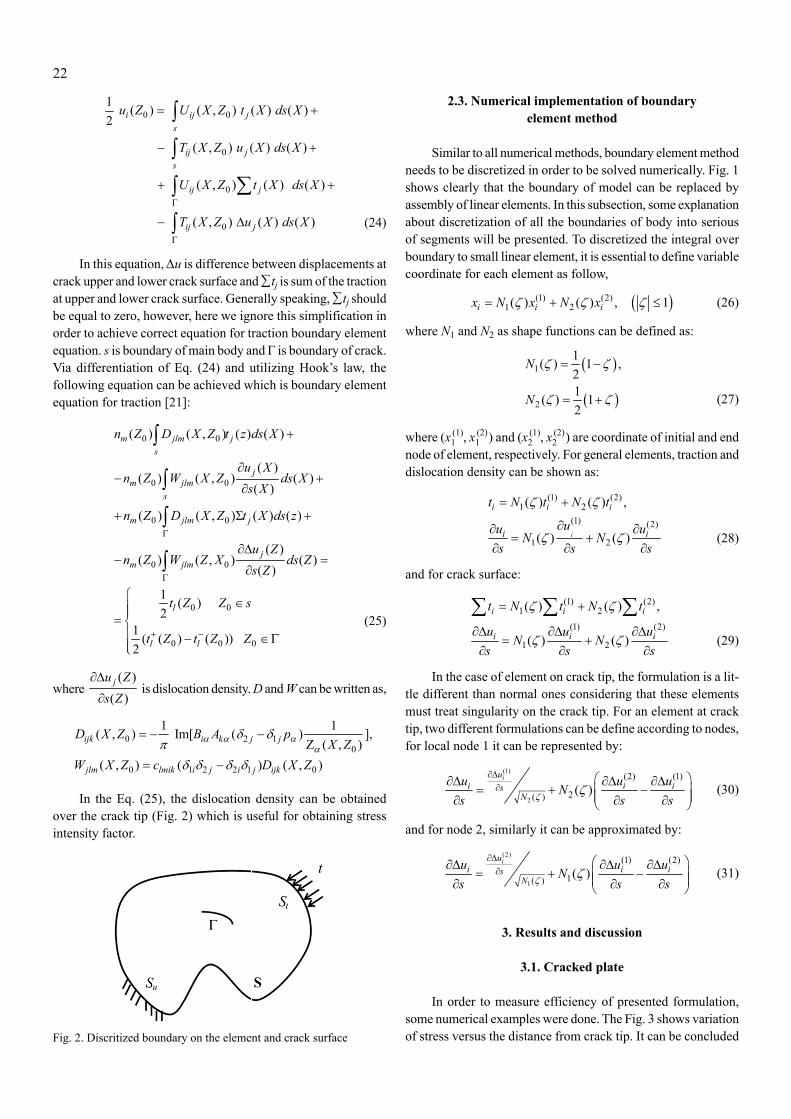
In the Eq. (25), the dislocation density can be obtained over the crack tip (Fig. 2) which is useful for obtaining stress intensity factor.
Fig. 2. Discritized boundary on the element and crack surface
2.3. Numerical implementation of boundary element method
Similar to all numerical methods, boundary element method needs to be discretized in order to be solved numerically. Fig. 1 shows clearly that the boundary of model can be replaced by assembly of linear elements. In this subsection, some explanation about discretization of all the boundaries of body into serious of segments will be presented. To discretized the integral over boundary to small linear element, it is essential to define variable coordinate for each element as follow,
(1) (2)1 2( ) ( ) , 1i i ix N x N x (26)
where N1 and N2 as shape functions can be defined as:
1
2
1( ) 1 ,21( ) 12
N
N
(27)
where (x1(1), x1
(2)) and (x2(1), x2
(2)) are coordinate of initial and end node of element, respectively. For general elements, traction and dislocation density can be shown as:
(1) (2)1 2
(1) (2)
1 2
( ) ( ) ,
( ) ( )i
i i i
i i
t N t N t
uu uN N
s s s
(28)
and for crack surface:
(1) (2)1 2
(1) (2)
1 2
( ) ( ) ,
( ) ( )
i i i
i i i
t N t N t
u u uN N
s s s
(29)
In the case of element on crack tip, the formulation is a lit-tle different than normal ones considering that these elements must treat singularity on the crack tip. For an element at crack tip, two different formulations can be define according to nodes, for local node 1 it can be represented by:
(1)
2
(2) (1)
2( ) ( )iu
i i isN
u u uNs s s
(30)
and for node 2, similarly it can be approximated by:
(2)
1
(1) (2)
1( ) ( )iu
i i isN
u u uNs s s
(31)
3. Results and discussion
3.1. Cracked plate
In order to measure efficiency of presented formulation, some numerical examples were done. The Fig. 3 shows variation of stress versus the distance from crack tip. It can be concluded

23
that the stress near crack tip has the highest amount and by moving far from crack tip, stress is decreased which show the accuracy of Eqs. (30) and (31) in treating singular integral near crack tips. The figure shows the variation of stress for three different paths with different angles. In order to show the influ-ence of crack length on stress intensity factor, the kinked crack was simulated. The result is shown in Fig. 4. By variation of θ and increasing the length of crack, the stress intensity factor for mode I increases and after pick at θ = 0 crack length decreases again to its lowest amount. The equation provided in reference [22] is used in this paper for obtaining stress intensity factor.
Fig. 3. Central crack in a rectangular piezoelectric plate, a/w = 0.06
Fig. 4. Variation of the normalized mode I stress intensity factor for a/b = 10, and 20
3.2. Piezoelectric plate with inclusion
In this subsection, first some equation for plate with inclu-sion will be presented, the results will be discussed. In the case when there are inclusions (Fig. 5), boundary element integral can be written for matrix s and inclusion Γ as:
00
00
1 ( ) ( , ) ( ) ( )2
( , ) ( ) ( ) s
s
u X U Z X t X ds X
T Z X u X ds X X s
10
10
1 ( ) ( , ) ( ) ( )2
( , ) ( ) ( )
u X U Z X t X ds X
T Z X u X ds X X
(32)
where 0 and 1 indicate the matrix and inclusion sub domain, respectively. After discretization and using linear or quadratic elements, Eq. (32) can be expressed as:
0 0 0 0 0 0 0 011 12 13 11 12 130 0 0 0 0 0 0 021 22 23 21 22 230 0 0 i 0 0 0 i031 32 33 31 32 33
i ii i i
A A A U B B B T
A A A T B B B U
A A A U B B B T
G T H U
(33)
where U0 and T– 0 represent the unknown nodal displacement and known nodal traction, respectively, on matrix; T0 and U– 0 are the unknown nodal traction and known nodal displacement on matrix; Ui is the unknown nodal displacement on interface: while Ti0and Tii express the unknown nodal traction on the interface for the matrix and inclusion, respectively.
The results of numerical examples are presented in Figs. 6 and 7.
Fig. 6. Variation of stress near circular inclusion in rectangular piezo-electric plate
Fig. 5. The rectangular piezoelectric with circular inclusion

24
Fig. 7. Variation of stress near circular and rectangular inclusion at centre of inclusion in piezoelectric plate
It is clear from Fig. 6 that near interface of circular inclusion (which is shown in Fig. 5) and matrix, the stress has its highest amount and when it goes far from interface, the stress decrease to its lowest amounts. So, it can be concluded that inclusion can have the effect similar to hole and crack. Another point in this figure is that for bigger inclusion, the higher amount of stress can happen. Fig. 7 compares the variation of stress near interface of rectangular and circular inclusion. The length of rectangular inclusion is equal to diameter of circular one. The variation of stress near interface of both inclusions is the same which shows that stress is independent of shape of inclusion.
3.3. Results of multiscale modelling
Let us to write the boundary element equation of grains again in local coordinate in order to talk comprehensively about this topic.
( ) ( , ) ( )
( , ) ( )
( , ) ( )
( , ) ( ) 1,...,
kc
knc
kc
knc
k k k k kij j ij j cS
k k kij j ncS
k k kij j cS
k k kij j ncS
C z u z T z z u z dS
T z z u z dS
U z z t z dS
U z z t z dS k number of grain
(34)
In Eq. (34), Tijk(z', z) and Uij
k(z', z) are fundamental solution for traction and displacement which can be obtained via Stroh formulation for each grain. Sc
H and SncH belong to boundary of
internal grain (contact boundary) and free boundary. Cijk refers to
free term. After obtaining traction and displacement, the average of micro-stress of a RVE can be calculated as;
, 1t
m t m m tij i jt S
x t dSV
(35)
where xik and tjk are the position vector which is located on RVE
boundary and their traction respectively.
Similarly, the average strain of RVE can be evaluated as;
, ,
, ,1
12
12
t
g
k
m t t tij i j j it V
Nk k ki j j it V
k
u u dVV
u u dVV
(36)
The divergence theory can be applied on Eq. (36) which leads to;
1
12
g knc
kc
k k k k kN i j j i ncSm
ij t k k k k kk i j j i cS
u n u n dS
V u n u n dS (37)
According to this assumption that for two grains which are located next to each other namely, u9 and u10, the displace-ment discontinuity are defined as δu
I = u9 – u10 and the normal vector of these grains are defined in such a way that u9 = –u10, respectively. So, the Eq. (37) takes the form
12
knc
kc
k k ki j j i ncSm
ij t k k ki j j i cS
u n u n dS
V u n u n dS (38)
In this section, the efficiency developed grain boundary formulation will be proved via some numerical examples. The properties of PZT-4 are utilized here in order to confirm the validation of numerical algorithm (Table 1).
The results of using these formulation in micro-mechanical analysis of piezoelectric ceramics are discussed as below.
Fig. 8 shows the relation between stress and strain in the RVE of homogenous piezoelectric ceramic of Fig. 9 which is subjected to tensile mechanical load in horizontal direction by considering piezoelectric effect and without piezoelectric effect. It can be concluded that the piezoelectric coupling has significant influence on fracture criteria of aggregates which means that through considering the piezoelectricity and for
Fig. 8. Normal strain and normal stress of polycrystalline in Fig. 9 which is subjected to tensile mechanical load in horizontal direction by considering piezoelectric effects and without piezoelectric effects

25
a specified amount of strain, the polycrystalline aggregate without piezoelectric effect can experience more stress. It could be deduced that for a specific strain energy which is entered to the system, the piezoelectric aggregate, it should be divided between mechanical and electric effects, while in polycrystal-
TABLE 1
The property of PZT-4 piezoelectric ceramic
c11, (N/m2) c13, (N/m2) c33, (N/m2) c44, (N/m2) e31, (C/m2) e33, (C/m2) e15, (C/m2) κ11, (C/Vm) κ33, (C/Vm)13.9×1010 7.78×10¹⁰ 11.3×10¹⁰ 2.56×10¹⁰ –6.98 13.8 13.4 60×1010 54.7×10¹⁰
Fig. 9. The fracture pattern for polycrystalline aggregate which is subjected to tensile mechanical load in horizontal direction (a) without piezo-electric effects and (b) with piezoelectric effects
line without piezoelectricity this energy can only have influence on mechanical properties. The intergranular fracture criteria of this aggregate which is subjected to tensile mechanical load in horizontal direction by considering piezoelectric effect and without it are shown in Fig. 9.

26
Fig. 10. The influence of defect on mechanical behaviour of the barium titanate piezoelectric polycrystalline aggregates in Fig. 11 which is sub-jected to tensile mechanical load in horizontal direction
It can be concluded in this figure that by increasing the strain, the crack grows faster and faster. One of the interesting results which can be visited in Fig. 9 is that in the grain aggregate with piezoelectric effect, the fracture grows up faster. The reason that can justify this event is that after the crack is nucleated, the distance between two grains behaves like a capacitor and it injects opposite traction to the grains boundary. This traction can create the situation that the crack grow up faster than the time when there is no piezoelectric effects.
One of the interesting topics which can be studied in this area is the investigation of predefined crack on the polycrystalline ag-gregates and how they can affect the behaviour of materials. In the manufacturing process it is normal to have defects and sometimes these defects have a considerable influence on materials. Obvi-ously, the boundary condition, the type and direction of loads et al. can have influence on how these defects affect the materials.
Fig. 10 compares the influence of defects and their loca-tion which is shown in Fig. 11 on mechanical behaviour of piezoelectric polycrystalline aggregate by applying tensile mechanical load in horizontal direction. It could be concluded that apart from the location of the defects, they can decrease the strength of the materials. However, some of them, according to their position, can change the fracture pattern of the polycrystal-line aggregate. Fig. 11 demonstrates the fracture pattern of the polycrystalline aggregates with predefine crack which can be seen in the Fig. 11(a).
The stress-strain curve of these polycrystalline is presented in Fig. 10. As it was mentioned, the external force is applied in the form of the displacement in horizontal or x direction and in Fig. 11 it has more effect on normal mode displacement in cases 1 and 2 than cases 3 and 4. Hence it may be noticed that the normal mode has more effect than tangential mode in grow-ing of the effective displacement. This claim can be seen in the right hand side of Fig. 10 that cases 1 and 2 have more effect in the intergranular fracture of polycrystalline aggregate.
4. Summary
Response of piezoelectric materials was investigated through multiscale boundary element methods. Based on results of presented investigations the following conclusions were formulated:1. The shape of interface does not have a great influence on
the stress intensity.2. The maximum stress can be hardly influenced by the cou-
pling between mechanical and electrical properties which means that through considering the piezoelectricity and for a specified amount of strain, the polycrystalline aggregate without piezoelectric effect can experience more stress.
3. Considering the dimensions of inclusion it can be concluded that inclusion can have the effect similar to the hole and the crack; bigger inclusion leads to an increase of the stress.
Acknowledgement
The research leading to these results has received funding from the Peo-ple Programme (Marie Curie Actions) of the European Union’s Seventh Framework Programme FP7/2007-2013/ under REA grant agreement No. PITN-GA-2013-606878.
REFERENCES
[1] A.C. Roy, D. Mohanta, Scr. Mater. 61, 891 (2009).[2] M.M. Vijatović, J.D. Bobić, B.D. Stojanović, Sci. Sinter. 40, 235
(2008).[3] Y. Iqbal, A. Jamal, R. Ullah, M.N. Khan, R. Ubic, Bull. Mater.
Sci. 35, 387 (2012).[4] H.A. Sosa, Int. J. Solids Struct. 29, 2613 (1992).[5] C.C. Fulton, H.J. Gao, Appl. Mech. Rev. 50, S56 (1997).

27
[6] C.V. Verhosel, J.J.C. Remmers, M.A. Gutierrez, Int. J. Num. Meth. Eng. 82, 966 (2009).
[7] R. Fenner, Boundary Element Methods for Engineers: Part II Plane Elastic Problems, London 2014.
[8] D. Beskos, G. Maier (Eds.), Boundary Element Advances in Solid Mechanics. Wien 2014.
[9] T.A. Cruse, Comp. Struct. 3, 509 (1973). [10] M.D. Snyder, T.A. Cruse, Int. J. Fract. 11, 315 (1975).
[11] I. Pasternak, Eng. Anal. Bound. Elem. 36, 1931 (2012).[12] W.L. Yin, Int. J. Solids Struct. 37, 5257 (2000).[13] A.R. Khoei, F. Jahanbakhshi, A. Aramoon, Mech. Mater. 83, 40
(2015).[14] R.M. Sencu, Z. Yang, Y.C. Wang, Eng. Fract. Mech. 163, 499
(2016).[15] V.G. Kouznetsova, M.G.D. Geers, W.A.M. Brekelmans, Comput.
Meth. Appl. Mech. Eng. 193, 5525 (2004).
Fig. 11. The influence of pre-existing crack on behaviour of barium titanate piezoelectric polycrystalline aggregate (a) before applying external load, (b) after applying external load
28
[16] M. Silani, S. Ziaei-Rad, H. Talebi, T. Rabczuk, Theor. Appl. Fract. Mech. 74, 30 (2014).
[17] H.D. Espinosa, P.D. Zavattieri, Mech. Mater. 35, 333 (2003)[18] H.D. Espinosa, P.D. Zavattieri, Mech. Mater. 35, 365 (2003).[19] G.K. Sfantos, M.H. Aliabadi, Int. J. Numer. Meth. Eng. 69, 1590
(2007).
[20] D. Fang, J. Liu, Fracture Mechanics of Piezoelectric and Ferro-electric Solids. Beijing 2013.
[21] K.M. Liew, Y. Sun, S. Kitipornchai, Int. J. Numer. Meth. Eng. 69, 729 (2007).
[22] Y.-B. Wang, Y.-Z. Sun, Eng. Fract. Mech. 72, 2128-2143 (2005).