multiplexer - voice transcoder e1-xlc - cronyx micro · multiplexer - voice transcoder e1-xlc...
TRANSCRIPT
1.0R / 01.06.2002
1234567890123456789012345678901212345678901234567890123456789012123456789012345678901234567890121234567890112345678901234567890123456789012123456789012345678901234567890121234567890123456789012345678901212345678901
Features
• Desktop or the card for 19” 3U
Cronyx rack
• Two E1 links (PCM-30)
• Distance up to 1.5 km (up to 2.5 km
for rack design models)
• Synchronous V.35, RS-530, RS-
449, RS-232, X.21 or Ethernet
interface
• Built-in HDLC buffer (for models
with synchronous interface)
• Asynchronous mode for the RS-
232 interface
• Random timeslot selection
• G.704 frame structure
• Transparent for signaling CRC4
multi-frame structure
• Selection from 14 available voice
codecs
• Digital port rate 24 to 1984 kbit/
sec
• Synchronization from internal oscil-
lator, E1/0 receiver path, E1/1
receiver path, or digital interface
(DTE1 or DTE2)
• Digital, local and remote loops
• Built-in Bit Error Rate tester (BER
tester);
• RS-232 port for monitoring and
control
• Emergency alarms (“dry contacts”)
• Built-in power supply unit from
mains or battery
• Upgradable firmware
• SSE Certificate of the State Com-
munications Committee of the
Russian Federation No. OS/1-
SPD-19
Copyright © 2002 Cronyx
Multiplexer - Voice Transcoder
E1-XLC
E1-XLC MultiplexerUser’s Guide
MULTIPLEXER - VOICE TRANSCODER E1-XLC123456789012345678901234567890121234567890123456789012345678901212345678901234567890123456789012123456789012345678901234567890121234567890123456123456789012345678901234567890121234567890123456789012345678901212345678901234567890123456789012123456789012345678901234567890121234567890123456
Copyright © 2002 Cronyx 2
Contents
Technical specifications ...............................................................................4
Description ....................................................................................................5
Supplied items ...........................................................................................6
Order code .................................................................................................6
Controls and indicators ................................................................................7
Front panel controls ..................................................................................7
Front panel indicators ...............................................................................7
Jumpers .....................................................................................................8
Line impedance ......................................................................................8
Programming mode ...............................................................................8
Micro switches ...........................................................................................8
Console ......................................................................................................9
Configuration parameters .......................................................................... 10
Saving settings ........................................................................................ 10
Device synchronization .......................................................................... 10
HDLC buffer.............................................................................................. 10
Clock inversion ........................................................................................ 10
Voice data compression algorithm......................................................... 11
Receiver path sensitivity ......................................................................... 11
Ethernet interface mode .......................................................................... 11
Ethernet packet filtering .......................................................................... 11
Timeslot 16 mode .................................................................................... 13
CRC4 Multi-frame synchronism.............................................................. 13
Service line position in the E1 frame ...................................................... 13
Starting timeslot ....................................................................................... 13
Number of timeslots................................................................................. 13
Digital port asynchronous mode ............................................................ 13
Loss of synchronization action .............................................................. 15
Receiver path synchronization ............................................................... 15
CTS generation logic ............................................................................... 15
Synchronization modes.............................................................................. 15
Common synchronization ...................................................................... 15
DTE emulation ......................................................................................... 16
DTE1 emulation mode ......................................................................... 16
DTE2 emulation mode ......................................................................... 16
Clock parameter requirements ............................................................... 17
X.21 interface............................................................................................ 17
12345678901234567890123456789012123456789012345678901234567890121234567890123456789012345678901212345678901234567890123456789012123456789012345671234567890123456789012345678901212345678901234567890123456789012123456789012345678901234567890121234567890123456789012345678901212345678901234567
Copyright © 2002 Cronyx 3
MULTIPLEXER - VOICE TRANSCODER E1-XLC
Loops ........................................................................................................... 18
Normal operations ................................................................................... 18
Local loop................................................................................................. 18
Remote loop ............................................................................................. 18
Digital loop................................................................................................ 18
Emergency alarm ........................................................................................ 18
Rear panel connectors................................................................................ 20
Control via the console ............................................................................... 23
Ethernet interface ........................................................................................ 26
Firmware upgrade ....................................................................................... 26
Synchronous data transfer. ........................................................................ 27
Synchronous link design problems. ...................................................... 28
Cable diagrams............................................................................................ 31
V.35 cable for connection to the DCE using external transmission
clock, for model /B-V35 ........................................................................ 31
V.35 cable for connection to the DCE using external transmission
clock, for model /B-M ........................................................................... 31
V.35 cable for connection to the DCE using external transmission and
reception clock, for model /B-V35 ....................................................... 31
V.35 cable for connection to the DCE using external transmission and
reception clock, for model /B-M .......................................................... 31
V.35 cable, for model /B-M ....................................................................... 32
RS-449 cable, for model /B-M .................................................................. 32
RS-232 cable, for model /B-M .................................................................. 32
RS-530, for model /B-M ............................................................................ 32
Cable for connecting two devices, for model /B-M................................ 33
X.21 cable, for model /B-M....................................................................... 33
V.35 cable, for model /R-M ....................................................................... 33
RS-530 cable, for model /R-M .................................................................. 33
RS-449 cable, for model /R-M .................................................................. 34
RS-232 cable, for model /R-M .................................................................. 34
V.35 cable for connection to the DCE using external transmission
clock, for model /R-M ........................................................................... 34
V.35 cable for connection to the DCE using external transmission and
reception clock, for model /R-M .......................................................... 34

MULTIPLEXER - VOICE TRANSCODER E1-XLC123456789012345678901234567890121234567890123456789012345678901212345678901234567890123456789012123456789012345678901234567890121234567890123456123456789012345678901234567890121234567890123456789012345678901212345678901234567890123456789012123456789012345678901234567890121234567890123456
Copyright © 2002 Cronyx 4
Technical specifications
Compressor
Supported voice codecs G.726 (16 kbit/sec, 24 kbit/sec, 32 kbit/sec,
40 kbit/sec)
G.727 (Embedded Codes)
G.721-1984 (16-level) 32 kbit/sec
Tellabs 24 kbit/sec
Alternate (4 -level) 16 kbit/sec
Alternate (3 -level) 16 kbit/sec
Conexant (data optimized) 32 kbit/sec
Digital interface
Data transmission rate 24 to 1984 kbit/sec (Nx8) for all synchronization
types, except external,
64 to 1984 kbit/sec (Nx64) for external
synchronization
Clock signal TXC, RXC, ETC, ERC
Modem signals DTR, DSR, CTS, RTS, CD
E1 interface
Encoding HDB3
Line impedance 120 Ohms balanced (twisted pairs), or
75 Ohms unbalanced (coaxial),
jumper-selectable
Signal level at the receiver input
for desktop design 0 to -36 dB (up to 1.5 km over 0.6 mm twisted pairs)
for rack design 0 to -43 dB (up to 2.5 km over 0.6 mm twisted pairs)
Transmitter path synchronization from internal oscillator, or
from the E1/0 link receiver, or
from the E1/1 link receiver, or from the digital port
Jitter attenuator In receiver or transmitter path,
attenuation up to 120UIpp
Frame structure According to G.704
Multi-frames CRC4
Link rate negotiation controlled slip buffers
in receiver paths
Connector removable terminal
Emergency alarm interface
Relay contact current up to 250 mA
Relay contact voltage up to 175 VDC
Control port
Interface type RS-232
Data transmission protocol asynchronous, 9600 bit/sec, 8N1
Connector DB9 female
Diagnostic modes
Loops digital (on the digital interface), or
local (in the G.703 line on the local
device), or
remote (on the G.703 line on the remote
device)
enabled by front panel switches
or via the control port
BER tester enabled by front panel switches
or via the control port
12345678901234567890123456789012123456789012345678901234567890121234567890123456789012345678901212345678901234567890123456789012123456789012345671234567890123456789012345678901212345678901234567890123456789012123456789012345678901234567890121234567890123456789012345678901212345678901234567
Copyright © 2002 Cronyx 5
MULTIPLEXER - VOICE TRANSCODER E1-XLC
Description
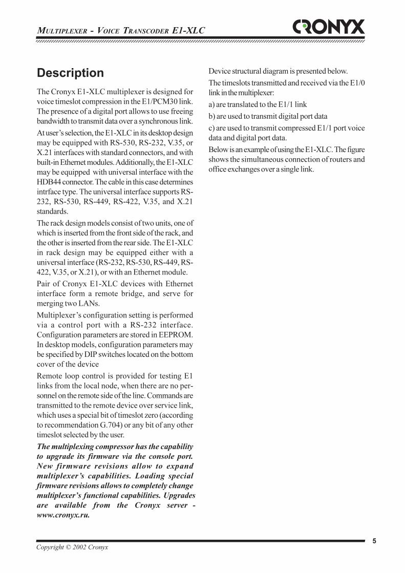
The Cronyx E1-XLC multiplexer is designed for
voice timeslot compression in the E1/PCM30 link.
The presence of a digital port allows to use freeing
bandwidth to transmit data over a synchronous link.
At user’s selection, the E1-XLC in its desktop design
may be equipped with RS-530, RS-232, V.35, or
X.21 interfaces with standard connectors, and with
built-in Ethernet modules. Additionally, the E1-XLC
may be equipped with universal interface with the
HDB44 connector. The cable in this case determines
intrface type. The universal interface supports RS-
232, RS-530, RS-449, RS-422, V.35, and X.21
standards.
The rack design models consist of two units, one of
which is inserted from the front side of the rack, and
the other is inserted from the rear side. The E1-XLC
in rack design may be equipped either with a
universal interface (RS-232, RS-530, RS-449, RS-
422, V.35, or X.21), or with an Ethernet module.
Pair of Cronyx E1-XLC devices with Ethernet
interface form a remote bridge, and serve for
merging two LANs.
Multiplexer’s configuration setting is performed
via a control port with a RS-232 interface.
Configuration parameters are stored in EEPROM.
In desktop models, configuration parameters may
be specified by DIP switches located on the bottom
cover of the device
Remote loop control is provided for testing E1
links from the local node, when there are no per-
sonnel on the remote side of the line. Commands are
transmitted to the remote device over service link,
which uses a special bit of timeslot zero (according
to recommendation G.704) or any bit of any other
timeslot selected by the user.
The multiplexing compressor has the capability to upgrade its firmware via the console port. New firmware revisions allow to expand multiplexer’s capabilities. Loading special firmware revisions allows to completely change multiplexer’s functional capabilities. Upgrades are available from the Cronyx server -
www.cronyx.ru.
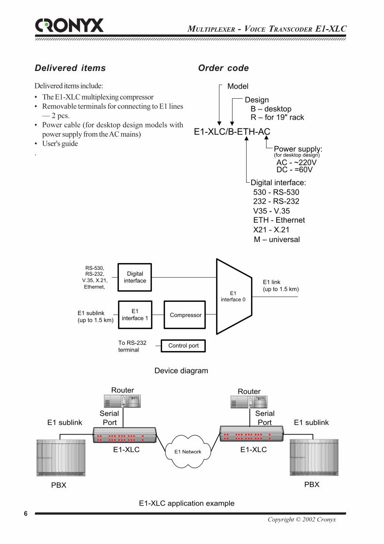
Device structural diagram is presented below.
The timeslots transmitted and received via the E1/0
link in the multiplexer:
a) are translated to the E1/1 link
b) are used to transmit digital port data
c) are used to transmit compressed E1/1 port voice
data and digital port data.
Below is an example of using the E1-XLC. The figure
shows the simultaneous connection of routers and
office exchanges over a single link.
MULTIPLEXER - VOICE TRANSCODER E1-XLC123456789012345678901234567890121234567890123456789012345678901212345678901234567890123456789012123456789012345678901234567890121234567890123456123456789012345678901234567890121234567890123456789012345678901212345678901234567890123456789012123456789012345678901234567890121234567890123456
Copyright © 2002 Cronyx 6
Power supply:
AC - ~220VDC - =60V
E1-XLC/B-ETH-AC
Model
DesignB – desktop
Digital interface:530 - RS-530232 - RS-232V35 - V.35ETH - EthernetX21 - X.21M – universal
R – for 19" rack
(for desktop design)
E1-XLC application example
Router
E1-XLC E1 Network
Router
PBX PBX
E1 sublink E1 sublink
E1-XLC
SerialPort
SerialPort
Device diagram
To RS-232terminal
E1 link(up to 1.5 km)
E1 sublink(up to 1.5 km)
RS-530,RS-232,
V.35, X.21,Ethernet,
Control port
Digitalinterface
E1interface 1
E1interface 0
Compressor
Delivered items
Delivered items include:
• The E1-XLC multiplexing compressor
• Removable terminals for connecting to Å1 lines
— 2 pcs.
• Power cable (for desktop design models with
power supply from the AC mains)
• User's guide
.
Order code

12345678901234567890123456789012123456789012345678901234567890121234567890123456789012345678901212345678901234567890123456789012123456789012345671234567890123456789012345678901212345678901234567890123456789012123456789012345678901234567890121234567890123456789012345678901212345678901234567
Copyright © 2002 Cronyx 7
MULTIPLEXER - VOICE TRANSCODER E1-XLC
Controls and indicators
Front panel controlsBERT - three-position switch used to enable the BER
tester:
BERT BER-tester
L0 Enabled, Å1/0 line testing
OFF Disabled, normal operation
L1 Enabled, Å1/1 line testing
LOOP - two two-position switches (LOOP1 and
LOOP2) selecting loop type and link number.
LOOP1 Loop
LOC Local loop on selected Å1 line
DIG Digital interface loop
REM Remote loop on selected Å1 line
LOOP2 Loop enabled on
L0 Link 0
OFF Loop disabled
L1 Link 1
The table shows the positions of LOOP1 and
LOOP2 switches for enabling the required loop.
Loop LOOP1 LOOP2
Disabled Any OFF
Local on the Å1/0 line LOC L0
Local on the Å1/1 line LOC L1
Remote on the Å1/0 line REM L0
Remote on the Å1/1 line REM L1
On the digital interface DIG L0/L1
Front panel indicators
Indicator Purpose
PWR power supply
DI presence of interface board (rack
design models only)
RTS RTS and CD signals from the digital
interface
RERR errors on the remote device
LERR errors on the local device
TST test modes
Front panel controls (desktop design)
Front panel controls (19" rack design)
MULTIPLEXER - VOICE TRANSCODER E1-XLC123456789012345678901234567890121234567890123456789012345678901212345678901234567890123456789012123456789012345678901234567890121234567890123456123456789012345678901234567890121234567890123456789012345678901212345678901234567890123456789012123456789012345678901234567890121234567890123456
Copyright © 2002 Cronyx 8
The TST indicator is designed to show the selected
test mode:
Does not light Normal operation
Lights BER tester
enabled
Flashes Local loop enabled
Single Remote loop enabled
flashes
Double Digital loop enabled
flashes
During normal operation, the LERR indicator is
on during loss of input signal in E1 line, or during
loss of frame or multi-frame synchronism, during
digital port FIFO buffer errors, and during loss
of ETC clock, when devices are synchronized from
the digital interface. When the BER tester is
enabled, the LERR indicator lights when there are
errors in the line.
The RERR indicator is on during loss of frame
synchronism at the remote device (bit A of timeslot
is zero).
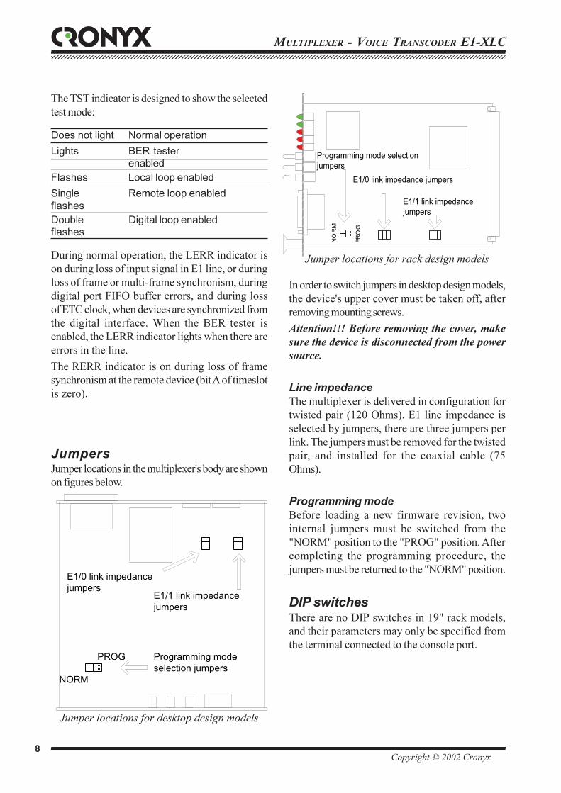
JumpersJumper locations in the multiplexer's body are shown
on figures below.
In order to switch jumpers in desktop design models,
the device's upper cover must be taken off, after
removing mounting screws.
Attention!!! Before removing the cover, make
sure the device is disconnected from the power
source.
Line impedance
The multiplexer is delivered in configuration for
twisted pair (120 Ohms). E1 line impedance is
selected by jumpers, there are three jumpers per
link. The jumpers must be removed for the twisted
pair, and installed for the coaxial cable (75
Ohms).
Programming mode
Before loading a new firmware revision, two
internal jumpers must be switched from the
"NORM" position to the "PROG" position. After
completing the programming procedure, the
jumpers must be returned to the "NORM" position.
DIP switchesThere are no DIP switches in 19" rack models,
and their parameters may only be specified from
the terminal connected to the console port.
Jumper locations for desktop design models
E1/0 link impedancejumpers
E1/1 link impedancejumpers
Programming modeselection jumpers
NORM
PROG
E1/0 link impedance jumpers
E1/1 link impedancejumpers
Programming mode selectionjumpers
NO
RM
PRO
G
Jumper locations for rack design models
12345678901234567890123456789012123456789012345678901234567890121234567890123456789012345678901212345678901234567890123456789012123456789012345671234567890123456789012345678901212345678901234567890123456789012123456789012345678901234567890121234567890123456789012345678901212345678901234567
Copyright © 2002 Cronyx 9
MULTIPLEXER - VOICE TRANSCODER E1-XLC
Timeslots used to compressvoice data
Device configuration
Bottom cover side view S
1S
3S
2
Timeslots used to transmitdigital port data
Group S1 — timeslots used for voice data
compression.
Group S2 — timeslots used for digital port data
transmission.
Group S3 — device configuration.
The following notations are used when describing
DIP switch positions:
the OFF position
the ON position
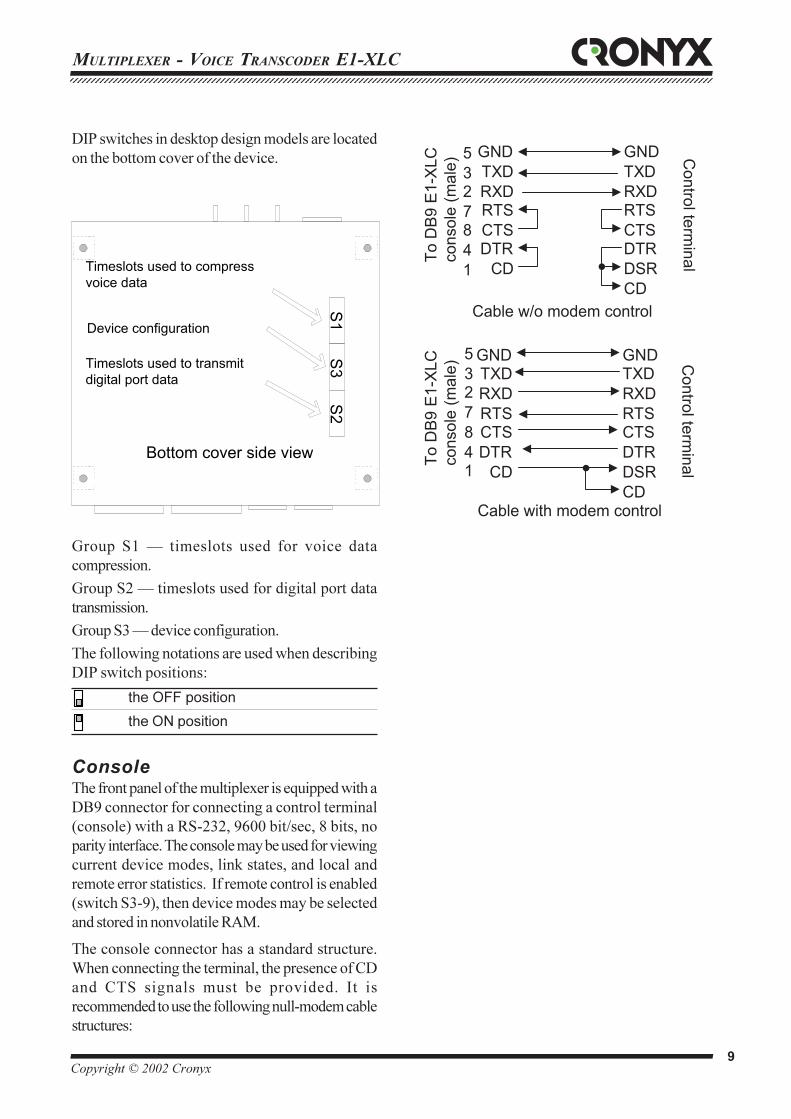
Console
The front panel of the multiplexer is equipped with a
DB9 connector for connecting a control terminal
(console) with a RS-232, 9600 bit/sec, 8 bits, no
parity interface. The console may be used for viewing
current device modes, link states, and local and
remote error statistics. If remote control is enabled
(switch S3-9), then device modes may be selected
and stored in nonvolatile RAM.
The console connector has a standard structure.
When connecting the terminal, the presence of CD
and CTS signals must be provided. It is
recommended to use the following null-modem cable
structures:
DIP switches in desktop design models are located
on the bottom cover of the device.
To D
B9
E1-
XLC
cons
ole
(mal
e) Control term
inal
Cable with modem control
GNDTXDRXDRTSCTSDTR
CD
GNDTXDRXDRTSCTSDTRDSRCD
5327841
To D
B9
E1-
XLC
cons
ole
(mal
e)
Control term
inal
Cable w/o modem control
GNDTXDRXDRTSCTSDTR
CD
GNDTXDRXDRTSCTSDTRDSRCD
5327841
MULTIPLEXER - VOICE TRANSCODER E1-XLC123456789012345678901234567890121234567890123456789012345678901212345678901234567890123456789012123456789012345678901234567890121234567890123456123456789012345678901234567890121234567890123456789012345678901212345678901234567890123456789012123456789012345678901234567890121234567890123456
Copyright © 2002 Cronyx 10
Configuration parameters
Each time the E1-XLC multiplexer is switched on, it
is configured according to the specified parameters.
Configuration parameters for desktop design models
may be specified from the following two sources:
- DIP switches on the bottom cover of the device
- NVRAM, which stores parameters specified from
the console.
There are no DIP switches in 19" rack models.
Configuration parameters are stored in nonvolatile
RAM (NVRAM), and are specified from the terminal
connected to the console port, or via the monitoring
and control board (RMC).
Parameters settings
The S3-9 switch enables remote control of the device,
that is, setting parameters from the terminal connected
to the console port. During remote control, device
parameters are stored in nonvolatile RAM
(NVRAM). When remote control is disabled,
NVRAM is not used, and parameters are set by DIP
switches only.
S3-9 Parameter settings
from DIP switches only, remote control
disabled, NVRAM is not used
from the remote terminal, parameters
are stored in the NVRAM, DIP switches
are not in use
Device synchronization
DIP switches S3-1, S3-2 specify device
synchronization mode:
S3-1:S3-2 Device synchronization
INT - internal oscillator
Link0 - from main link (E1/0)
receiver
Link1 - from sub-channel (E1/1)
receiver
Port - from the digital interface
(except models equipped with
Ethernet interface)
If synchronization from the digital interface is enabled,
then the data transmission rate over this interface must
be a multiple of 64 kbit/sec. For Ethernet equipped
models, it is not permitted to select the
synchronization from the digital interface mode.
HDLC buffer
The S3-3 DIP switch enables the operation of the
HDLC buffer in the receiver and transmitter paths of
the digital port. The buffer is designed to operate in
the DTE emulation mode, when common
synchronization is not present. If the HDLC buffer is
enabled, then the digital port operates in the DTE
mode, and requires input reception and
transmission clocks (ERC and ETC).
For information, that is more detailed see section
“Synchronous data transmission”.
S3-3 HDLC buffer
buffer disabled
buffer enabled
This DIP switch is not used in Ethernet interface
multiplexer.
Clock inversion
When using INT, From Link 0, or From Link 1
synchronization, there is a delay of TXD data in
relation to the TXC clock. The total time delay is
comprised of the delay in the cable, and the delay in
the digital interface of the equipment connected to
the modem. As a result, data errors may appear when
selecting some rates.
12345678901234567890123456789012123456789012345678901234567890121234567890123456789012345678901212345678901234567890123456789012123456789012345671234567890123456789012345678901212345678901234567890123456789012123456789012345678901234567890121234567890123456789012345678901212345678901234567
Copyright © 2002 Cronyx 11
MULTIPLEXER - VOICE TRANSCODER E1-XLC
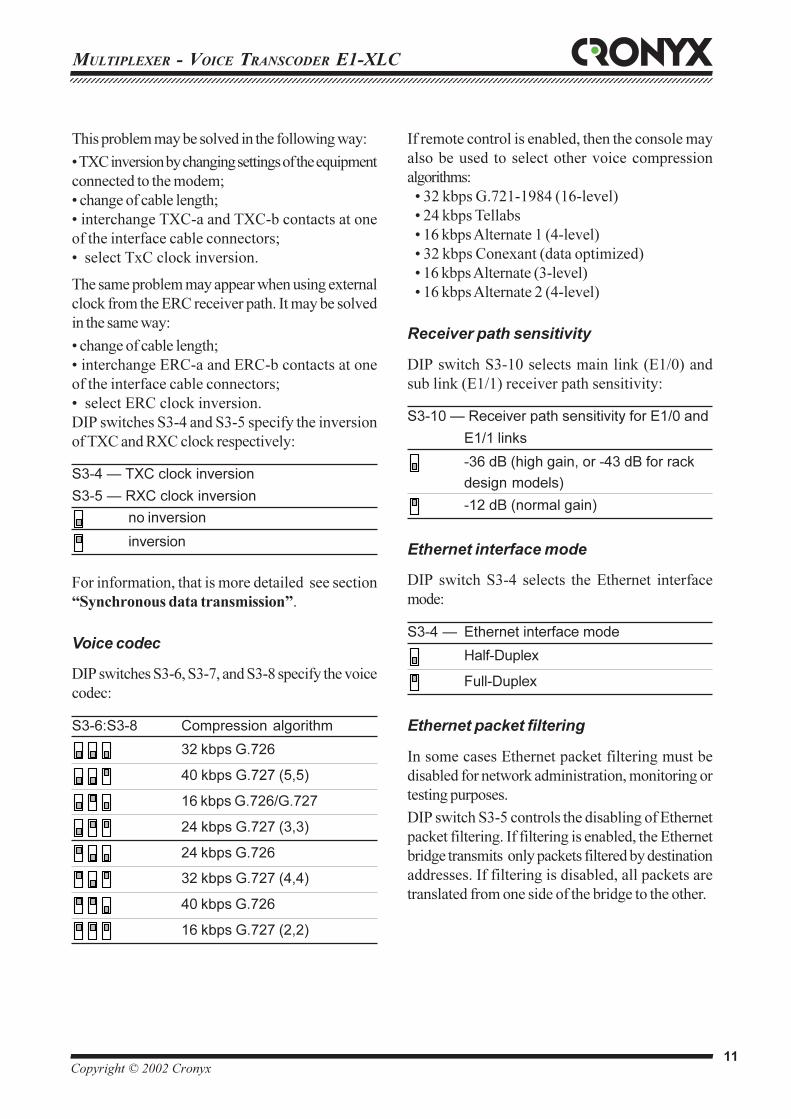
This problem may be solved in the following way:
• TXC inversion by changing settings of the equipment
connected to the modem;
• change of cable length;
• interchange TXC-a and TXC-b contacts at one
of the interface cable connectors;
• select TxC clock inversion.
The same problem may appear when using external
clock from the ERC receiver path. It may be solved
in the same way:
• change of cable length;
• interchange ERC-a and ERC-b contacts at one
of the interface cable connectors;
• select ERC clock inversion.
DIP switches S3-4 and S3-5 specify the inversion
of TXC and RXC clock respectively:
S3-4 — TXC clock inversion
S3-5 — RXC clock inversion
no inversion
inversion
For information, that is more detailed see section
“Synchronous data transmission”.
Voice codec
DIP switches S3-6, S3-7, and S3-8 specify the voice
codec:
S3-6:S3-8 Compression algorithm
32 kbps G.726
40 kbps G.727 (5,5)
16 kbps G.726/G.727
24 kbps G.727 (3,3)
24 kbps G.726
32 kbps G.727 (4,4)
40 kbps G.726
16 kbps G.727 (2,2)
If remote control is enabled, then the console may
also be used to select other voice compression
algorithms:
• 32 kbps G.721-1984 (16-level)
• 24 kbps Tellabs
• 16 kbps Alternate 1 (4-level)
• 32 kbps Conexant (data optimized)
• 16 kbps Alternate (3-level)
• 16 kbps Alternate 2 (4-level)
Receiver path sensitivity
DIP switch S3-10 selects main link (E1/0) and
sub link (E1/1) receiver path sensitivity:
S3-10 — Receiver path sensitivity for E1/0 and
E1/1 links
-36 dB (high gain, or -43 dB for rack
design models)
-12 dB (normal gain)
Ethernet interface mode
DIP switch S3-4 selects the Ethernet interface
mode:
S3-4 — Ethernet interface mode
Half-Duplex
Full-Duplex
Ethernet packet filtering
In some cases Ethernet packet filtering must be
disabled for network administration, monitoring or
testing purposes.
DIP switch S3-5 controls the disabling of Ethernet
packet filtering. If filtering is enabled, the Ethernet
bridge transmits only packets filtered by destination
addresses. If filtering is disabled, all packets are
translated from one side of the bridge to the other.
MULTIPLEXER - VOICE TRANSCODER E1-XLC123456789012345678901234567890121234567890123456789012345678901212345678901234567890123456789012123456789012345678901234567890121234567890123456123456789012345678901234567890121234567890123456789012345678901212345678901234567890123456789012123456789012345678901234567890121234567890123456
Copyright © 2002 Cronyx 12
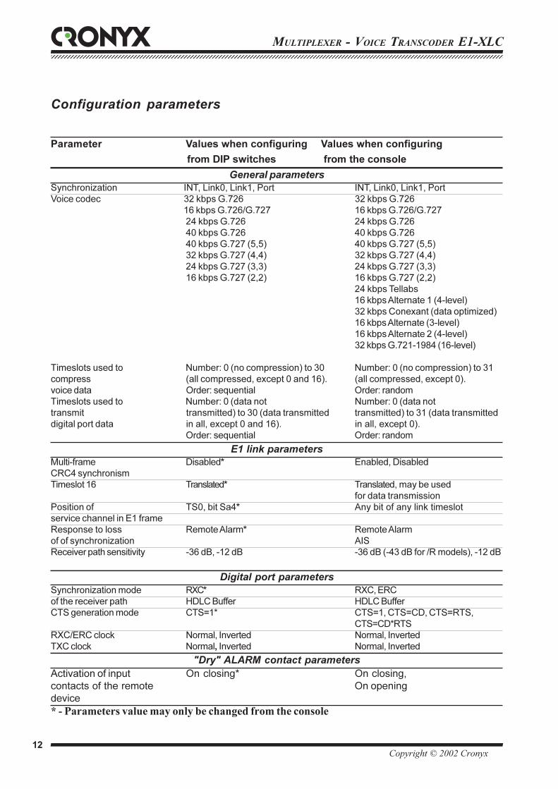
Parameter Values when configuring Values when configuring
from DIP switches from the console
General parameters
Synchronization INT, Link0, Link1, Port INT, Link0, Link1, Port
Voice codec 32 kbps G.726 32 kbps G.726
16 kbps G.726/G.727 16 kbps G.726/G.727
24 kbps G.726 24 kbps G.726
40 kbps G.726 40 kbps G.726
40 kbps G.727 (5,5) 40 kbps G.727 (5,5)
32 kbps G.727 (4,4) 32 kbps G.727 (4,4)
24 kbps G.727 (3,3) 24 kbps G.727 (3,3)
16 kbps G.727 (2,2) 16 kbps G.727 (2,2)
24 kbps Tellabs
16 kbps Alternate 1 (4-level)
32 kbps Conexant (data optimized)
16 kbps Alternate (3-level)
16 kbps Alternate 2 (4-level)
32 kbps G.721-1984 (16-level)
Timeslots used to Number: 0 (no compression) to 30 Number: 0 (no compression) to 31
compress (all compressed, except 0 and 16). (all compressed, except 0).
voice data Order: sequential Order: random
Timeslots used to Number: 0 (data not Number: 0 (data not
transmit transmitted) to 30 (data transmitted transmitted) to 31 (data transmitted
digital port data in all, except 0 and 16). in all, except 0).
Order: sequential Order: random
E1 link parameters
Multi-frame Disabled* Enabled, Disabled
CRC4 synchronism
Timeslot 16 Translated* Translated, may be used
for data transmission
Position of TS0, bit Sa4* Any bit of any link timeslot
service channel in E1 frame
Response to loss Remote Alarm* Remote Alarm
of of synchronization AIS
Receiver path sensitivity -36 dB, -12 dB -36 dB (-43 dB for /R models), -12 dB
Digital port parameters
Synchronization mode RXC* RXC, ERC
of the receiver path HDLC Buffer HDLC Buffer
CTS generation mode CTS=1* CTS=1, CTS=CD, CTS=RTS,
CTS=CD*RTS
RXC/ERC clock Normal, Inverted Normal, Inverted
TXC clock Normal, Inverted Normal, Inverted
"Dry" ALARM contact parameters
Activation of input On closing* On closing,
contacts of the remote On opening
device
* - Parameters value may only be changed from the console
Configuration parameters
12345678901234567890123456789012123456789012345678901234567890121234567890123456789012345678901212345678901234567890123456789012123456789012345671234567890123456789012345678901212345678901234567890123456789012123456789012345678901234567890121234567890123456789012345678901212345678901234567
Copyright © 2002 Cronyx 13
MULTIPLEXER - VOICE TRANSCODER E1-XLC
S3-5 — Ethernet packet filtering
Filtering enabled
Filtering disabled
Timeslot 16 mode
Mode of timeslot 16 usage may only be changed
from the console. Timeslot 16 is usually used to
transmit signaling information, in this case
transparent translation of timeslot 16 from link
E1/1 into E1/0 must be provided. The console
may be used to enable the timeslot 16 for data
transmission.
When specifying configuration parameters using
DIP switches, timeslot 16 is translated, and may
not be used for data transmission.
CRC4 multi-frame synchronism
When specifying multiplexer configuration
parameters from the console, it is possible to enable
CRC4 multi-frame synchronization control.
When specifying multiplexer configuration
parameters from the DIP switches, CRC4 multi-
frame synchronization control is disabled.
Service channel position in the E1 frame
Remote device control and statistics exchange are
performed over the service link, which occupies one
bit of the E1 frame. When console is used to specify
configuration parameters, there is a capability to
specify a random bit of any timeslot for service link
position.
When using DIP switches, the service link is
located in bit Sa4 of timeslot zero according to
recommendation ITU-T G.704.
Starting timeslot
DIP switches S1-1...S1-5 specify the number of
the starting timeslot for compression. Link E1/1
timeslots, starting from the selected one, will be
transcoded into ADPCM according to the algorithm
selected, and then transmitted to link E1/0.
DIP switches S2-1...S2-5 specify the number of the
starting timeslot for data transmission. Data from the
digital port will be inserted into link E1/0 timeslots,
beginning from the starting one.
Number of timeslots
DIP switches S1-6...S1-10 specify the number of
timeslots used for transcoding into ADPCM.
Timeslots, which are not transcoded and not used
for data transmission, are translated from link E1/1
into link E1/0 and back without any modification.
DIP switches S2-6...S2-10 specify the number of
E1/1 links used for data transmission. Data fully
occupy timeslots, if ADPCM transmission is not
specified to be performed in the same timeslots. Data
partially occupy timeslots, if ADPCM transmission
is specified to be performed in the same timeslots. In
this case the data transmission rate over the digital
port will depend upon the selected compression
algorithm.
Digital port asynchronous mode
The digital port may support both the asynchronous
and the synchronous data transmission modes. When
specifying configuration parameters from the console,
it is possible to select one of the following rates: 1200,
2400, 4800, 9600, 19200, 38400, 57600, or
115200 bit/sec. The 8N1, 7P1, 8P1 asynchronous
symbol formats are supported.
MULTIPLEXER - VOICE TRANSCODER E1-XLC123456789012345678901234567890121234567890123456789012345678901212345678901234567890123456789012123456789012345678901234567890121234567890123456123456789012345678901234567890121234567890123456789012345678901212345678901234567890123456789012123456789012345678901234567890121234567890123456
Copyright © 2002 Cronyx 14
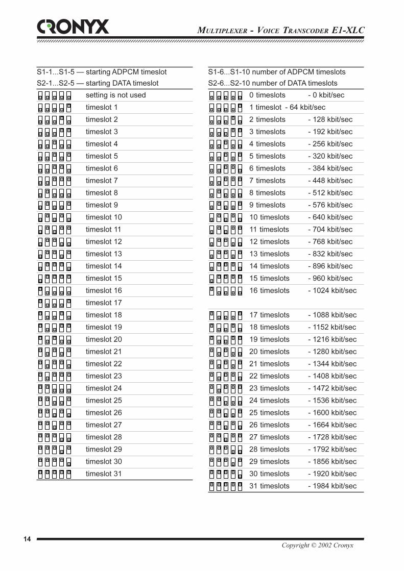
S1-1...S1-5 — starting ADPCM timeslot
S2-1...S2-5 — starting DATA timeslot
setting is not used
timeslot 1
timeslot 2
timeslot 3
timeslot 4
timeslot 5
timeslot 6
timeslot 7
timeslot 8
timeslot 9
timeslot 10
timeslot 11
timeslot 12
timeslot 13
timeslot 14
timeslot 15
timeslot 16
timeslot 17
timeslot 18
timeslot 19
timeslot 20
timeslot 21
timeslot 22
timeslot 23
timeslot 24
timeslot 25
timeslot 26
timeslot 27
timeslot 28
timeslot 29
timeslot 30
timeslot 31
S1-6...S1-10 number of ADPCM timeslots
S2-6...S2-10 number of DATA timeslots
0 timeslots - 0 kbit/sec
1 timeslot - 64 kbit/sec
2 timeslots - 128 kbit/sec
3 timeslots - 192 kbit/sec
4 timeslots - 256 kbit/sec
5 timeslots - 320 kbit/sec
6 timeslots - 384 kbit/sec
7 timeslots - 448 kbit/sec
8 timeslots - 512 kbit/sec
9 timeslots - 576 kbit/sec
10 timeslots - 640 kbit/sec
11 timeslots - 704 kbit/sec
12 timeslots - 768 kbit/sec
13 timeslots - 832 kbit/sec
14 timeslots - 896 kbit/sec
15 timeslots - 960 kbit/sec
16 timeslots - 1024 kbit/sec
17 timeslots - 1088 kbit/sec
18 timeslots - 1152 kbit/sec
19 timeslots - 1216 kbit/sec
20 timeslots - 1280 kbit/sec
21 timeslots - 1344 kbit/sec
22 timeslots - 1408 kbit/sec
23 timeslots - 1472 kbit/sec
24 timeslots - 1536 kbit/sec
25 timeslots - 1600 kbit/sec
26 timeslots - 1664 kbit/sec
27 timeslots - 1728 kbit/sec
28 timeslots - 1792 kbit/sec
29 timeslots - 1856 kbit/sec
30 timeslots - 1920 kbit/sec
31 timeslots - 1984 kbit/sec
12345678901234567890123456789012123456789012345678901234567890121234567890123456789012345678901212345678901234567890123456789012123456789012345671234567890123456789012345678901212345678901234567890123456789012123456789012345678901234567890121234567890123456789012345678901212345678901234567
Copyright © 2002 Cronyx 15
MULTIPLEXER - VOICE TRANSCODER E1-XLC
Loss of synchronization action
When specifying configuration parameters from
the console, it is possible to select on of the two
responses to loss of E1 link synchronization:
Loss of sync action: Remote Alarm - bit A of
zero timeslot is set into the transmitted E1 frame.
Loss of sync action: AIS - the AIS alarm indication
signal (“blue code”) is transmitted.
When specifying configuration parameters from
DIP switches, this parameter has the Remote
Alarm value.
Receiver path synchronization
The receiver path synchronization from the
external source mode is used when connecting to
DCE devices, which do not have external
synchronization from the digital port (RS-232,
V.35, RS-530) mode. In this case the modem
outputs clock data received at the ERC input. The
FIFO buffer is used to correct data phase at the
RXD digital port output in relation to ERC clock.
For the correct operation of the buffer (no
overflows and underflows), the clock frequency
received from the line must be the same as the
frequency at the ERC input. This condition is
maintained when the data transmission link has a
common clock source. Otherwise, there may be
periodic errors related to FIFO buffer overflows and
underflows. The frequency of these errors depends
on the discrepancy value between these two
frequencies. In cases when it is not possible to
provide common clock, and the data transmitted over
the network comply with the HDLC protocol, the
HDLC mode of the FIFO buffer must be used.
CTS generation logic
When specifying configuration from the console,
it is possible to select one of the four rules for
CTS output signal generation:
CTS=1, CTS=CD, CTS=RTS, or CTS=CD*RTS.
When specifying configuration using DIP
switches, it is always CTS=1.
Synchronization modesThe E1-XLC requires the presence of common
synchronization in the network. Transmitter path
synchronization may come from:
• The internal oscillator (INT)
• Link E1/0 (Link0) receiver path
• Link E1/1 (Link1) receiver path
• The ETC input of the digital port - DTE1 and DTE2
emulation mode
The following figures contain synchronization
examples.
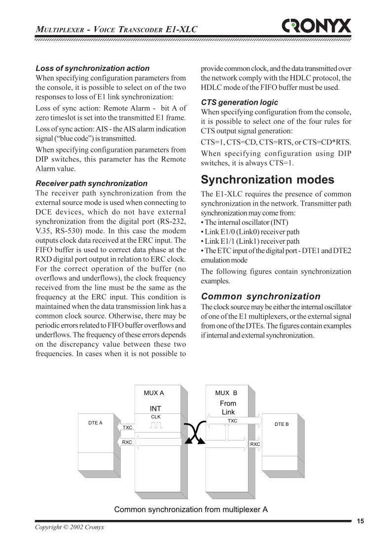
Common synchronizationThe clock source may be either the internal oscillator
of one of the E1 multiplexers, or the external signal
from one of the DTEs. The figures contain examples
if internal and external synchronization.
MUX А
TXC
RXC
DTE A DTE BCLK
MUX В
RXC
TXC
FromLinkINT
Common synchronization from multiplexer A

MULTIPLEXER - VOICE TRANSCODER E1-XLC123456789012345678901234567890121234567890123456789012345678901212345678901234567890123456789012123456789012345678901234567890121234567890123456123456789012345678901234567890121234567890123456789012345678901212345678901234567890123456789012123456789012345678901234567890121234567890123456
Copyright © 2002 Cronyx 16
DTE emulationTwo clock inputs - reception and transmission (ERC
and ETC) are provided for connecting the E1-XLC
multiplexer over the RS-232, V.35, RS-530 interface
to DCE devices in the synchronous mode. Only ETC
is provided for the X.21 interface.
DTE1 emulation mode
The DTE1 emulation mode is used when connecting
to DCE devices, which have external synchronization
from the digital port (RS-232, V.35, RS-530, X.21)
mode. In this case a pair of devices connected over
the digital port (RS-232, V.35, RS-530, X.21)
transparently translates the clock frequency.
MUX А
TXC
RXC
ETC
DTE A DTE B
CLK
MUX В
TXC
RXC
FromPort
FromLink
Common synchronization from DTE A
MUX АDCE DTE
MUX В
TXD
TXC
TXD
RXD
TXD RXD
RXC ETC
RXD
ETC RXC
From Port
DTE1 emulation mode using external transmission clock
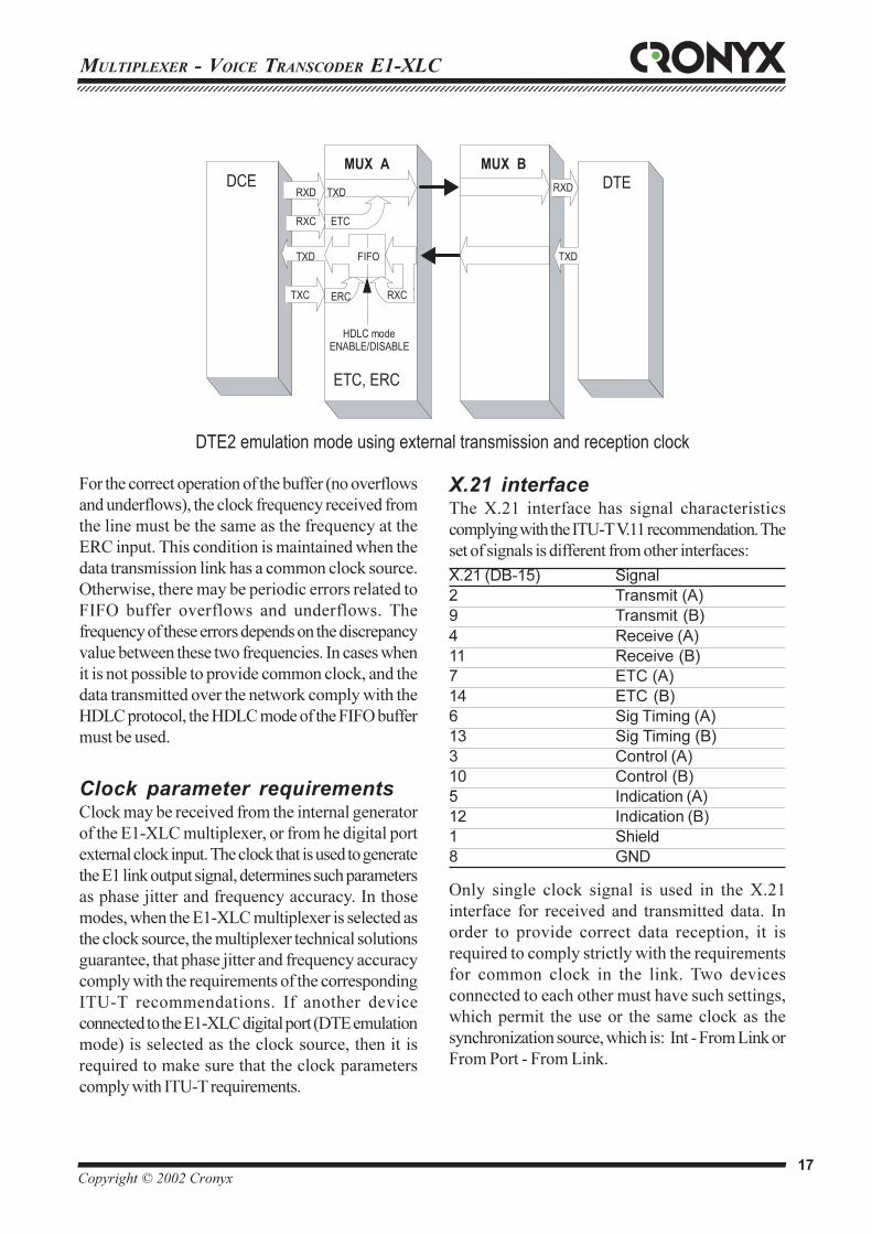
DTE2 emulation mode
The DTE2 emulation mode is used when
connecting to DCE devices, which do not have
external synchronization from the digital port (RS-
232, V.35, RS-530) mode. In this case, the E1-XLC
multiplexer receives data to the digital port
according to the clock received on the ETC input,
and transmits according to the clock received on the
ERC input. The FIFO buffer is used to correct data
phase at the RXD digital port output in relation to
ERC clock.
12345678901234567890123456789012123456789012345678901234567890121234567890123456789012345678901212345678901234567890123456789012123456789012345671234567890123456789012345678901212345678901234567890123456789012123456789012345678901234567890121234567890123456789012345678901212345678901234567
Copyright © 2002 Cronyx 17
MULTIPLEXER - VOICE TRANSCODER E1-XLC
For the correct operation of the buffer (no overflows
and underflows), the clock frequency received from
the line must be the same as the frequency at the
ERC input. This condition is maintained when the
data transmission link has a common clock source.
Otherwise, there may be periodic errors related to
FIFO buffer overflows and underflows. The
frequency of these errors depends on the discrepancy
value between these two frequencies. In cases when
it is not possible to provide common clock, and the
data transmitted over the network comply with the
HDLC protocol, the HDLC mode of the FIFO buffer
must be used.
Clock parameter requirementsClock may be received from the internal generator
of the E1-XLC multiplexer, or from he digital port
external clock input. The clock that is used to generate
the E1 link output signal, determines such parameters
as phase jitter and frequency accuracy. In those
modes, when the E1-XLC multiplexer is selected as
the clock source, the multiplexer technical solutions
guarantee, that phase jitter and frequency accuracy
comply with the requirements of the corresponding
ITU-T recommendations. If another device
connected to the E1-XLC digital port (DTE emulation
mode) is selected as the clock source, then it is
required to make sure that the clock parameters
comply with ITU-T requirements.
MUX АDCE DTE
MUX В
TXD
TXC
TXD
RXD
TXD RXD
RXC ETC
RXD
ETC, ERC
ERC RXC
FIFO
DTE2 emulation mode using external transmission and reception clock
HDLC modeENABLE/DISABLE
X.21 interfaceThe X.21 interface has signal characteristics
complying with the ITU-T V.11 recommendation. The
set of signals is different from other interfaces:
X.21 (DB-15) Signal
2 Transmit (A)
9 Transmit (B)
4 Receive (A)
11 Receive (B)
7 ETC (A)
14 ETC (B)
6 Sig Timing (A)
13 Sig Timing (B)
3 Control (A)
10 Control (B)
5 Indication (A)
12 Indication (B)
1 Shield
8 GND
Only single clock signal is used in the X.21
interface for received and transmitted data. In
order to provide correct data reception, it is
required to comply strictly with the requirements
for common clock in the link. Two devices
connected to each other must have such settings,
which permit the use or the same clock as the
synchronization source, which is: Int - From Link or
From Port - From Link.
MULTIPLEXER - VOICE TRANSCODER E1-XLC123456789012345678901234567890121234567890123456789012345678901212345678901234567890123456789012123456789012345678901234567890121234567890123456123456789012345678901234567890121234567890123456789012345678901212345678901234567890123456789012123456789012345678901234567890121234567890123456
Copyright © 2002 Cronyx 18
The Indication signal corresponds to the CD signal,and the Control signal corresponds to the RTS signal.
Loops
Normal operationThe LOOP2 switch is in the “OFF” position.
Local loopThe LOOP1 switch is in the LOC position; the
LOOP2 switch specifies the number of the E1 link.
Remote loopThe LOOP1 switch is in the REM position; theLOOP2 switch specifies the number of the E1 link.The remote device automatically enables and disablesthe local loop by request.
Digital loopThe LOOP1 switch is in the DIG position; theLOOP2 switch may be either in the L0, or in the L1position
Emergency alarms
The emergency alarm interface is used for turningon en external executive unit (ringer, buzzer,console indicator, etc.) during an emergency – forexample, loss of carrier, loss of synchronization,power failure. This is enabled by “dry” (that is,not connected to any electrical circuits of themodem) relay contacts. Additionally, the interfacehas a pair of input contacts, the state of which(closed/open) is transmitted to the remote deviceand leads to relay activation. If the multiplexer isinstalled in an unserviced room, then the inputcontacts may be used, for example, for remoteclimate sensors, door opening signals, etc.
A switch must close the input contacts, whichis isolated from any electrical circuit! Non-compliance with this requirement may lead tomultiplexer malfunction.
When power supply and the carrier are present,contact 3 is connected to contact 1. During poweror carrier loss, contact 3 breaks circuit 1 andconnects to contact 2 (the “alarm” state).
The external sensor has two operating modes:closing-sensitive and opening-sensitive. Themode is set to closing-sensitive by default. When
contact 5 connects to contact 4, the remote deviceswitches to alarm state.
The console may be used to set the mode toopening-sensitive, in this case, the sensor mustbe normally closed, and alarm is raised on theremote device.
The “Alarm” connector
6
4
21
3
5
1
3
5
2
4
6
Contact
1 Connected to the middle contact (3)
during normal operation. Opened
during error
2 Opened during normal operation.
Connected to the middle contact (3)
during error
3 Middle contact
4 GND
5 Input contact
6 GND
Modem "dry" contacts
"Alarm" state shown
External input sensor (user's equipment)
5
6
3
4
1
2
+5v
12345678901234567890123456789012123456789012345678901234567890121234567890123456789012345678901212345678901234567890123456789012123456789012345671234567890123456789012345678901212345678901234567890123456789012123456789012345678901234567890121234567890123456789012345678901212345678901234567
Copyright © 2002 Cronyx 19
MULTIPLEXER - VOICE TRANSCODER E1-XLC
MUX А
RXD
RTS
DTE A DTE BMUX В
RTS
CD
DSR
TXD
DSR
CD
CTS
TXD
RXD
CTS
"ON"
Carrier OK
"OFF"
Carier OK
cts=f(cd,rts) cts=f(cd,rts)
MUX А
RXD
RTS
DTE A DTE BMUX В
RTS
CD
DSR
TXD
DSR
CD
CTS
TXD
RXD
CTS
"OFF"
Carrier OK
"ON"
Carier OK
cts=f(cd,rts) cts=f(cd,rts)
MUX А
RXD
RTS
DTE A DTE BMUX В
RTS
CD
DSR
TXD
DSR
CD
CTS
TXD
RXD
CTS
Carrier OK
"ON"
Carrier OK
"ON"
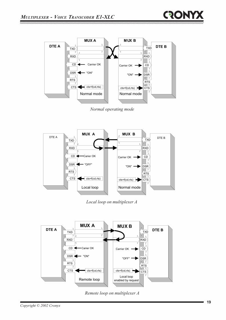
Normal mode Normal mode
Local loop Normal mode
Remote loopLocal loop
enabled by request
cts=f(cd,rts) cts=f(cd,rts)
Remote loop on multiplexer A
Local loop on multiplexer A
Normal operating mode
MULTIPLEXER - VOICE TRANSCODER E1-XLC123456789012345678901234567890121234567890123456789012345678901212345678901234567890123456789012123456789012345678901234567890121234567890123456123456789012345678901234567890121234567890123456789012345678901212345678901234567890123456789012123456789012345678901234567890121234567890123456
Copyright © 2002 Cronyx 20
Rear panel connectors
The rear panel of the device contains the digital
interface connector, and E1 link removable terminals.
The digital port of the desktop design multiplexer
with the V.35 interface (/B-V35) is equipped with a
standard M-34 connector (female):
Contact Signal Direction
P TD-a Receive
S TD-b Receive
R RD-a Transmit
T RD-b Transmit
U ET-a Receive
W ET-b Receive
Y TC-a Transmit
AA TC-b Transmit
BB ERC-a Receive
Z ERC-b Receive
V RC-a Transmit
X RC-b Transmit
C RTS Receive
H DTR Receive
E DSR Transmit
D CTS Transmit
F DCD Transmit
A CGND —
B SGND —
Models /B-232, /B-530 (desktop design) have digital
ports with RS-232 and RS-530, respectively,
equipped with a DB25 connector (female):
Cont. DB25 RS-530 RS-232 Direction.
2 TXD-a TXD Receive
14 TXD-b — Receive
3 RXD-a RXD Transmit
16 RXD-b — Transmit
24 ETC-a ETC Receive
11 ETC-b — Receive
15 TXC-a TXC Transmit
12 TXC-b — Transmit
17 RXC-a RXC Transmit
9 RXC-b — Transmit
21 ERC-a ERC Receive
18 ERC-b Receive
4 RTS-a RTS Receive
19 RTS-b — Receive
20 DTR-a DTR Receive
23 DTR-b — Receive
6 DSR-a DSR Transmit
22 DSR-b — Transmit
5 CTS-a CTS Transmit
13 CTS-b — Transmit
8 CD-a CD Transmit
10 CD-b — Transmit
1,7 GND GND —
MUX А
RXD
RTS
DTE A DTE BMUX В
RTS
CD
DSR
TXD
DSR
CD
CTS
TXD
RXD
CTS
"ON"
Carrier OK
"ON"
Digital loop Normal mode
"ON"
cts=f(cd,rts) cts=f(cd,rts)
Digital loop
12345678901234567890123456789012123456789012345678901234567890121234567890123456789012345678901212345678901234567890123456789012123456789012345671234567890123456789012345678901212345678901234567890123456789012123456789012345678901234567890121234567890123456789012345678901212345678901234567
Copyright © 2002 Cronyx 21
MULTIPLEXER - VOICE TRANSCODER E1-XLC
Models /B-M (desktop design) have a HDB44
connector (female) with a universal interface:
Cont. V.35 RS-530 RS-232 X.21
10 TXD-a TXD-a TXD Transmit(A)
25 TXD-b TXD-b — Transmit(B)
8 RXD-a RXD-a RXD Receive(A)
9 RXD-b RXD-b — Receive(B)
6 ETC-a ETC-a ETC ETC(A)
7 ETC-b ETC-b — ETC(B)
2 TXC-a TXC-a TXC SigTiming(A)
3 TXC-b TXC-b — SigTiming(B)
5 RXC-a RXC-a RXC —
4 RXC-b RXC-b — —
17 ERC-a ERC-a ERC —
18 ERC-b ERC-b — —
14 RTS RTS-a RTS Control(A)
29 — RTS-b — Control(B)
11 DTR DTR-a DTR —
26 — DTR-b — —
13 DSR DSR-a DSR —
28 — DSR-b — —
15 CTS CTS-a CTS —
30 — CTS-b — —
12 CD CD-a CD Indication(A)
27 — CD-b — Indication(B)
1,16 GND GND GND GND
31 SEL-0* SEL-0* SEL-0* SEL-0
33 SEL-1 SEL-1* SEL-1 SEL-1*
35 SEL-2 SEL-2 SEL-2* SEL-2
37 SEL-3 SEL-3* SEL-3* SEL-3*
39 SEL-4* SEL-4 SEL-4 SEL-4
41 SEL-5* SEL-5 SEL-5 SEL-5
43 SEL-6* SEL-6 SEL-6 SEL-6
32 DCE DCE DCE DCE
* - Connect the contact to GND
Models /B-X21 (desktop design with X.21 interface)
have a digital port equipped with a DB15 connector
(female):
DB-15 female Signal Direction
2 T(A) Receive
9 T(B) Receive
4 R(A) Transmit
11 R(B) Transmit
7 ETC(A) Receive
14 ETC(B) Receive
6 S(A) Transmit
13 S(B) Transmit
3 C(A) Receive
10 C(B) Receive
5 I(A) Transmit
12 I(B) Transmit
1, 8 GND —
Rear panel of the desktop design multiplexer
RCV RCVXMTXMT
GND
MULTIPLEXER - VOICE TRANSCODER E1-XLC123456789012345678901234567890121234567890123456789012345678901212345678901234567890123456789012123456789012345678901234567890121234567890123456123456789012345678901234567890121234567890123456789012345678901212345678901234567890123456789012123456789012345678901234567890121234567890123456
Copyright © 2002 Cronyx 22
Models /R-M (rack mounted) have a MDB36
connector (male) with a universal interface:
Cont. V.35 RS-530 RS-232 Direction.
17 TXD-a TXD-a TXD Receive
18 TXD-b TXD-b — Receive
12 RXD-a RXD-a RXD Transmit
11 RXD-b RXD-b — Transmit
19 ETC-a ETC-a ETC Receive
21 ETC-b ETC-b — Receive
32 ERC-a ERC-a ERC Receive
34 ERC-b ERC-b — Receive
3 TXC-a TXC-a TXC Transmit
4 TXC-b TXC-b — Transmit
13 RXC-a RXC-a RXC Transmit
14 RXC-b RXC-b — Transmit
15 RTS RTS-a RTS Receive
16 — RTS-b — Receive
1 DTR DTR-a DTR Receive
2 — DTR-b — Receive
10 DSR DSR-a DSR Transmit
9 — DSR-b — Transmit
8 CTS CTS-a CTS Transmit
7 — CTS-b — Transmit
6 CD CD-a CD Transmit
5 — CD-b — Transmit
20,22, GND GND GND —
24,26,28,30
23 SEL-0 SEL-0 SEL-0 —
25 SEL-1 SEL-1 SEL-1 —
27 SEL-2 SEL-2 SEL-2 —
29 SEL-3 SEL-3 SEL-3 —
31 SEL-4 SEL-4 SEL-4 —
33 SEL-5 SEL-5 SEL-5 —
35 SEL-6 SEL-6 SEL-6 —
36 DCE DCE DCE —
Rear panel of the 19" rack design multiplexer
GND
XMT
RCV
GND
XMT
RCV
12345678901234567890123456789012123456789012345678901234567890121234567890123456789012345678901212345678901234567890123456789012123456789012345671234567890123456789012345678901212345678901234567890123456789012123456789012345678901234567890121234567890123456789012345678901212345678901234567
Copyright © 2002 Cronyx 23
MULTIPLEXER - VOICE TRANSCODER E1-XLC
Control via the console
The front panel of the multiplexer is equipped with
a DB9 connector for connecting to a control
terminal (console) with a RS-232 interface. The
console may be used for viewing current device
modes, link states, and local and remote error
statistics. If remote control is enabled (DIP switch
S3-9), then device modes may be selected and
stored in nonvolatile RAM.
Models for 19" rack are not equipped with DIP
switches, and remote control is always enabled.
Some parameters are only available for setting from
the console (see table on page 12).
The console interface is designed as a simple
hierarchical menu. To select a command, you must
enter its number.
The “Statistics” mode is used for viewing current
information, link operating modes and statistic
counters.
The “Ñ” key allows clearing error counters of a local
device. The “R” key allows changing the display
update mode.
Counter Error type
BPV Line encoding violation
OOS Number of seconds during which
frame or multi-frame synchronization
was lost
Err For E1 links - number of seconds
during which BER tester errors were
present;
for serial ports - number of seconds
during which external synchronization
errors were present;
for Ethernet ports - Ethernet bridge
internal buffers overflow.
Event Number of seconds, during which
link-related events have taken place.
The meaning of an event depends on
the interface type.
Event counter values:
Interface Cause Event
type
Serial FIFO buffer error .
In the DTE2 mode (use of
ERC pulses) the requirement for
common clock for the link is not
fulfilled.
Async FIFO buffer error
1. Transmission rate or
asynchronous symbol format set
for the port do not correspond to
connected device settings.
2. The transmission rate in the
connected device deviates too
greatly from the rated value
E1 Controlled slip. Requirement for the
common synchronization in the link
in not fulfilled (Slip operation).
Ethernet Collision.
High Ethernet network segment
load.
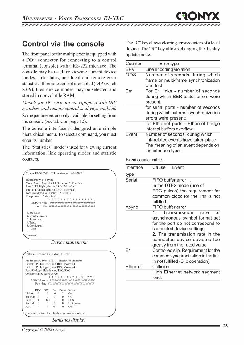
Statistics: Session #5, 0 days, 0:16:12
Mode: Smart, Sync: Link1, Timeslot16: TranslateLink 0: TP, High gain, no CRC4, Mon=Sa4
Link 1: TP, High gain, no CRC4, Mon=Sa4Port: 960 kbps, Half duplex, TXC, RXCCompressor: 32 kbps G.726
1 3 5 7 9 1 3 5 7 9 1 3 5 7 9 1 ADPCM voice: ###############x###############
Port data: ###############x###############
BPV OOS Err Event StatusLink 0: 0 0 0 0 Ok
far end: 0 0 0 0 OkLink 1: 0 161 0 0 LOS far end: 0 0 0 0 Unknown
Port: - - 0 0 Ok
C - clear counters, R - refresh mode, any key to break...
Statistics display
Cronyx E1-XLC-R /ETH revision A, 14/06/2002
Free memory: 511 bytesMode: Smart, Sync: Link1, Timeslot16: TranslateLink 0: TP, High gain, no CRC4, Mon=Sa4
Link 1: TP, High gain, no CRC4, Mon=Sa4Port: 960 kbps, Half duplex, TXC, RXCCompressor: 32 kbps G.726
1 3 5 7 9 1 3 5 7 9 1 3 5 7 9 1 ADPCM voice: ###############x###############
Port data: ###############x###############
1. Statistics2. Event counters
3. Loopback...4. Test...5. Configure...
0. Reset
Command: _
Device main menu
MULTIPLEXER - VOICE TRANSCODER E1-XLC123456789012345678901234567890121234567890123456789012345678901212345678901234567890123456789012123456789012345678901234567890121234567890123456123456789012345678901234567890121234567890123456789012345678901212345678901234567890123456789012123456789012345678901234567890121234567890123456
Copyright © 2002 Cronyx 24
The multiplexer uses the service channel to transmit
the values of its error counters to the remote device,
and to receive the values from remote error counters.
The state of E1 links is shown as a set of flags:
Flag Link state
OK Normal mode, frame and multi-
frame synchronism present
LOS Loss of signal in the line
AIS Reception of alarm indication signal
(“blue code”)
LOF Loss of frame synchronism
LOMF Loss of multi-frame synchronism
FARLOF Loss of frame synchronism at the
remote modem
AIS16 Reception of alarm indication signal
in timeslot 16
FARLOMF Loss of multi-frame synchronism at
the remote modem
CRCE CRC error
RCRCE CRC error at the remote modem
The “Loopback” menu is designed to control local,
digital and remote loops:
Control of the built-in BER tester and loops from
the console is enabled only when switches on the
front panel of the device are set to their neutral
positions. Loop and BER tester modes are not stored
in the nonvolatile RAM.
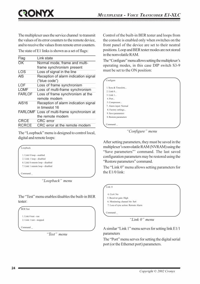
The “Configure” menu allows setting the multiplexer’s
operating modes, in this case DIP switch S3-9
must be set to the ON position:
The “Test” menu enables/disables the built-in BER
tester:
Loopback
1. Link 0 loop - enabled
2. Link 1 loop - disabled
6. Link 0 remote loop - disabled
7. Link 1 remote loop - disabled
Command: _
“Loopback” menu
BER Test
1. Link 0 test - run
2. Link 1 test - stopped
Command: _
“Test” menu
Configure
1. Sync & Timeslots...
2. Link 0...
3. Link 1...
4. Port...
5. Compressor...
7. Alarm input: Normal
8. Factory settings...
9. Save parameters
0. Restore parameters
Command: _
“Configure” menu
After setting parameters, they must be saved in the
multiplexer’s nonvolatile RAM (NVRAM) using the
“Save parameters”’ command. The last saved
configuration parameters may be restored using the
“Restore parameters” command.
The “Link 0” menu allows setting parameters for
the E1/0 link:
Link 0
4. Crc4: No
5. Receiver gain: High
6. Monitoring channel bit: Sa4
7. Loss of sync action: Remote Alarm
Command: _
“Link 0” menu
A similar “Link 1” menu serves for setting link E1/1
parameters
The “Port” menu serves for setting the digital serial
port (or the Ethernet port) parameters.
12345678901234567890123456789012123456789012345678901234567890121234567890123456789012345678901212345678901234567890123456789012123456789012345671234567890123456789012345678901212345678901234567890123456789012123456789012345678901234567890121234567890123456789012345678901212345678901234567
Copyright © 2002 Cronyx 25
MULTIPLEXER - VOICE TRANSCODER E1-XLC
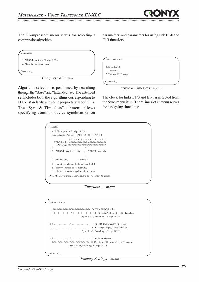
The “Compressor” menu serves for selecting a
compression algorithm:
Compressor
1. ADPCM algorithm: 32 kbps G.726
2. Algorithm Selection: Base
Command: _
“Compressor” menu
Algorithm selection is performed by searching
through the “Base” and “Extended” set. The extended
set includes both the algorithms corresponding to
ITU-T standards, and some proprietary algorithms.
The “Sync & Timeslots” submenu allows
specifying common device synchronization
Sync & Timeslots
1. Sync: Link1
2. Timeslots...
3. Timeslot 16: Translate
Command: _
“Sync & Timeslots” menu
parameters, and parameters for using link E1/0 and
E1/1 timeslots:
Timeslots
ADPCM algorithm: 32 kbps G.726
Sync data rate: 960 kbps ( 0*64 + 30*32 = 15*64 + 0)
1 3 5 7 9 1 3 5 7 9 1 3 5 7 9 1
ADPCM voice: ###############x###############Port data: ###############x###############
# #
# - ADPCM voice + port data . - ADPCM voice only
. .
# - port data only . - translate
0,1 - monitoring channel for Link 0 and Link 1
x - timeslot 16 reserved for signaling
* - blocked by monitoring channel for Link 0
Press <Space> to change, arrow keys to select, <Enter> to accept
“Timeslots...” menu
Factory settings
1. ###############*############### 30 TS - ADPCM voice
| | | | | | | | | | | | | | | * | | | | | | | | | | | | | | | 30 TS - data (960 kbps), TS16: Translate
Sync: Rcv1, Encoding: 32 kbps G.726
2. #. . . . . . . . . . . . . . * . . . . . . . . . . . . . . . 1 TS - ADPCM voice, 29 TS - voice
|. . . . . . . . . . . . . . * . . . . . . . . . . . . . . . 1 TS - data (32 kbps), TS16: Translate
Sync: Rcv1, Encoding: 32 kbps G.726
3. #. . . . . . . . . . . . . . * . . . . . . . . . . . . . . . 1 TS - ADPCM voice
|##############*############### 30 TS - data (1888 kbps), TS16: Translate
Sync: Rcv1, Encoding: 32 kbps G.726
Command: _
“Factory Settings” menu
The clock for links E1/0 and E1/1 is selected from
the Sync menu item. The “Timeslots” menu serves
for assigning timeslots:

MULTIPLEXER - VOICE TRANSCODER E1-XLC123456789012345678901234567890121234567890123456789012345678901212345678901234567890123456789012123456789012345678901234567890121234567890123456123456789012345678901234567890121234567890123456789012345678901212345678901234567890123456789012123456789012345678901234567890121234567890123456
Copyright © 2002 Cronyx 26
To speed up parameters setting it is possible to use
one of the three factory presets for the most
widespread types of multiplexer usage, with
subsequent correction of some parameters.
Ethernet interface
The Ethernet interface corresponds to the 10BaseT
standard. Two devices with this interfaces form
a remote bridge, and are used for merging two
LANs. The remote bridge has the packet filtering
capability, that is, it is used to transmit only the
packets, the addresses of which is present in the
LAN at the other side of the link. Cronyx E1-XLC
with an Ethernet interface may perform Ethernet
packet compression by clearing packet padding bits,
the length of which is less than the permitted one.
The remote bridge formed by two Cronyx E1-XLÑ
devices has the following characteristics:
Interface type 10BaseT (UTP)
Connector type RJ45
Modes Half Duplex
Full Duplex
Filtering rate 15000packets/sec
LAN table size 10000MAC-addresses
Parameter settings related to the Ethernet interface
may be changed both from the terminal connected
to the console port, and using DIP switches (for
desktop design models).
The “Ethernet” connector
Firmware upgrade
The multiplexer’s firmware may be upgraded using
a PC and special software via the console port. The
firmware is available from the server located at the
following address - www.cronyx.ru. The detailed
loading procedure instructions are delivered with
sofrware.
12345678
TD+TD-
RD+Not usedNot used
RD-Not used Not used
1 8

12345678901234567890123456789012123456789012345678901234567890121234567890123456789012345678901212345678901234567890123456789012123456789012345671234567890123456789012345678901212345678901234567890123456789012123456789012345678901234567890121234567890123456789012345678901212345678901234567
Copyright © 2002 Cronyx 27
MULTIPLEXER - VOICE TRANSCODER E1-XLC
Synchronous data
transfer.
During synchronous data transfer, their modification
is performed in strictly determined points of time,
which are related to a special clock. The time during
which data may not be modified, is called a bit
interval. The receiver device must read data during
points of time, which are close to the middle of the
bit interval. Reading data at a bit interval boundary
leads to faults. As a rule, the transmitter device
modifies data at one of the clock signal edges, (for
example, at the rising edge), and the receiver device
reads the data at the other edge (the falling edge in
this case).
CLK
DATA 01 0 1Bit interval
Different interfaces use different clock signal
transmission modes. V.35, RS-530, RS-232 etc.,
interface type have special dedicated clock lines for
each data direction (receive and transmit). Received
RXD data are accompanied by RXC clock, and
transmitted TXD data are accompanied by TXC
clock.
Linear modem interface (G.703, xDSL, etc.) use
self-synchronizing codes (HDB3, Manchester,
2B1Q, etc.) to transmit data and clock over the same
wires. The self-synchronizing codes are characterized
by the fact that they do not contain long sequences
of the same layer. This allows using the phase lock
circuit at the receiver side to extract clock and data
from the received signal.
V.35, RS-530, RS-232 interface types may be of
DCE and DTE types. DCE interface types are
equipped with modems, while DTE interfaces are
equipped with computer-like devices. DCE
device types are clock sources for both data
transmission directions – both signals, the RXC
(received data clock) and the TXC (transmitted
data clock) are output signals for them. Here the
RXC – is a signal received by the modem from
the line, and extracted by the phase lock circuit. It
accompanies the RXD data received by the modem
and has the same direction.
RXC
RXD
TXD
TXC
DTE
DCE
ETC
CLOCK SOURCEINTRCVETC
The TXC clock accompanies data received by the
modem (TXD). A DTE device serves as a TXD data
signal source. The TXC clock arrives from the
modem, and its source may be an internal modem
clock generator (INT), the clock signal extracted by
the phase lock circuit from the signal received from
the line (RCV), or an external clock source (EXT).
As a rule, the external source is the signal received
at the ETC interface input.
During serial data transfer, in addition to bit
synchronization, there is need to determine byte
boundaries. The stream is divided into frames for
this purpose. The beginning of the frame serves as
the byte reference point. In order to transmit digitized
telephone data, the frame format described in the
ITU G.704 recommendation is used. The HDLC
standard is the most widely spread way to convert
bit streams into frames in computer networks.
FLAG ADDRESS CONTROL DATA CRC FLAG
HDLC frame format
MULTIPLEXER - VOICE TRANSCODER E1-XLC123456789012345678901234567890121234567890123456789012345678901212345678901234567890123456789012123456789012345678901234567890121234567890123456123456789012345678901234567890121234567890123456789012345678901212345678901234567890123456789012123456789012345678901234567890121234567890123456
Copyright © 2002 Cronyx 28
A certain bit sequence, called a flag, serves as a frame
separator. In the HDLC protocol the flag is
01111110. In this case, in order for this sequence
not to appear inside data, the staffing/destaffing
procedure is used to insert/remove zeroes in a
sequence of ones, which length exceeds five.
Synchronous link design problems.
As a rule, synchronous links are designed based
on the common clock principle. This means that a
data transmission link between two DTE devices
uses a single clock to synchronize all data streams
in the link. Clock is transmitted on the DCE-DTE
device junction over special lines and with the
help of self-synchronizing codes over
communication lines. In a simplest case, when
connecting two routers equipped with V.35
interfaces using synchronous modems for a
dedicated line, the clock source is the internal
generator of one of the modems (INT). The second
modem extracts the clock from the signal received
from the line (RCV). Both routers, as DTE
devices, receive clock from modems.
А
TXC
RXC
DTE A CLK
INT
DTE B
В
RXC
TXC
RCV
Common clock from device A
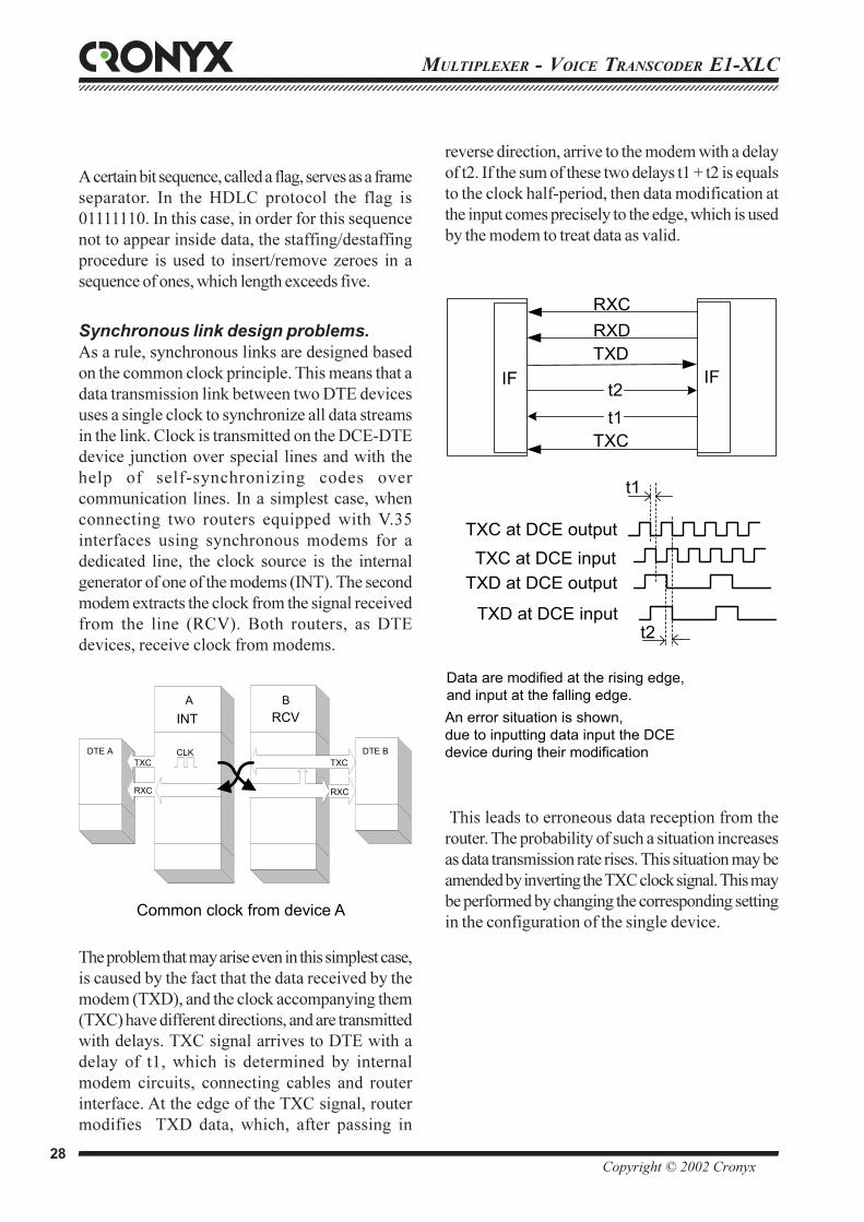
The problem that may arise even in this simplest case,
is caused by the fact that the data received by the
modem (TXD), and the clock accompanying them
(TXC) have different directions, and are transmitted
with delays. TXC signal arrives to DTE with a
delay of t1, which is determined by internal
modem circuits, connecting cables and router
interface. At the edge of the TXC signal, router
modifies TXD data, which, after passing in
reverse direction, arrive to the modem with a delay
of t2. If the sum of these two delays t1 + t2 is equals
to the clock half-period, then data modification at
the input comes precisely to the edge, which is used
by the modem to treat data as valid.
RXCRXDTXD
TXC
t2t1
t1
t2
IFIF
TXC at DCE output
TXD at DCE outputTXC at DCE input
TXD at DCE input
Data are modified at the rising edge, and input at the falling edge.An error situation is shown, due to inputting data input the DCE device during their modification
This leads to erroneous data reception from the
router. The probability of such a situation increases
as data transmission rate rises. This situation may be
amended by inverting the TXC clock signal. This may
be performed by changing the corresponding setting
in the configuration of the single device.
12345678901234567890123456789012123456789012345678901234567890121234567890123456789012345678901212345678901234567890123456789012123456789012345671234567890123456789012345678901212345678901234567890123456789012123456789012345678901234567890121234567890123456789012345678901212345678901234567
Copyright © 2002 Cronyx 29
MULTIPLEXER - VOICE TRANSCODER E1-XLC
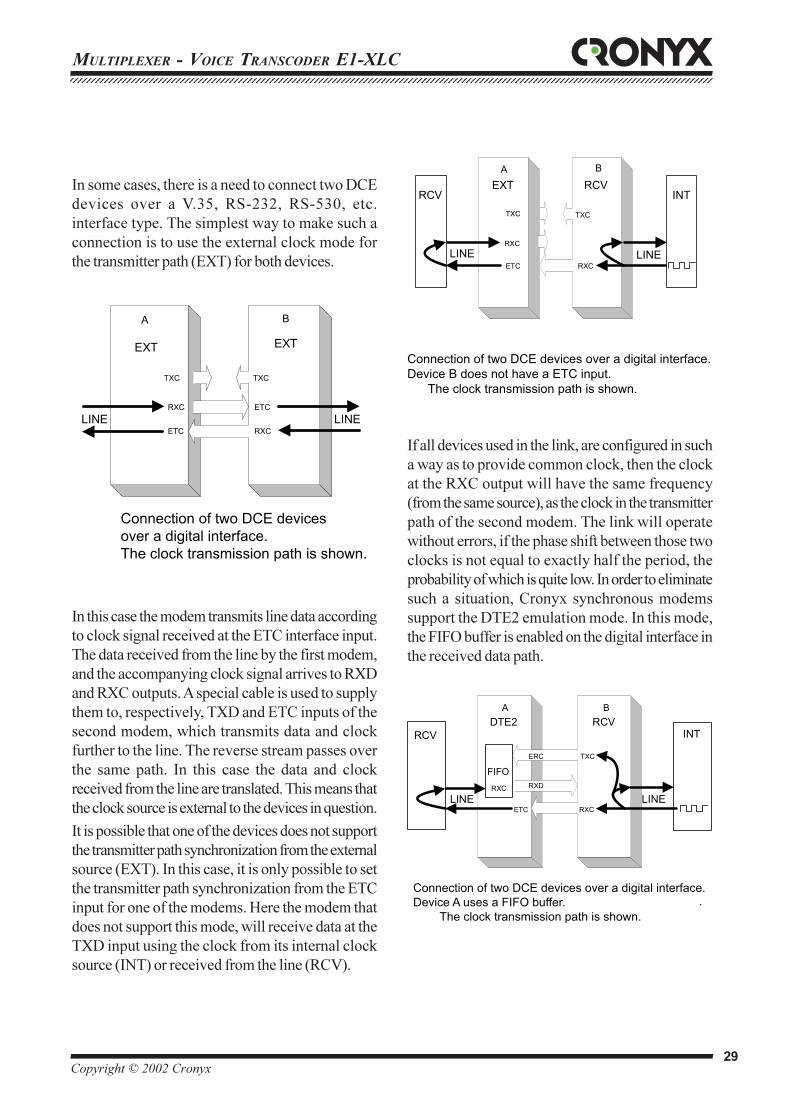
In some cases, there is a need to connect two DCE
devices over a V.35, RS-232, RS-530, etc.
interface type. The simplest way to make such a
connection is to use the external clock mode for
the transmitter path (EXT) for both devices.
А
TXC
RXCETC
В
TXC
EXTEXT
RXC ETC
LINELINE
Connection of two DCE devices over a digital interface.The clock transmission path is shown.
In this case the modem transmits line data according
to clock signal received at the ETC interface input.
The data received from the line by the first modem,
and the accompanying clock signal arrives to RXD
and RXC outputs. A special cable is used to supply
them to, respectively, TXD and ETC inputs of the
second modem, which transmits data and clock
further to the line. The reverse stream passes over
the same path. In this case the data and clock
received from the line are translated. This means that
the clock source is external to the devices in question.
It is possible that one of the devices does not support
the transmitter path synchronization from the external
source (EXT). In this case, it is only possible to set
the transmitter path synchronization from the ETC
input for one of the modems. Here the modem that
does not support this mode, will receive data at the
TXD input using the clock from its internal clock
source (INT) or received from the line (RCV).
А
TXC
RXCETC
В
TXC
RCVEXT
RXCLINE
RCV
LINE
INT
Connection of two DCE devices over a digital interface.Device B does not have a ETC input. The clock transmission path is shown.
If all devices used in the link, are configured in such
a way as to provide common clock, then the clock
at the RXC output will have the same frequency
(from the same source), as the clock in the transmitter
path of the second modem. The link will operate
without errors, if the phase shift between those two
clocks is not equal to exactly half the period, the
probability of which is quite low. In order to eliminate
such a situation, Cronyx synchronous modems
support the DTE2 emulation mode. In this mode,
the FIFO buffer is enabled on the digital interface in
the received data path.
А
TXC
RXCETC
ВRCVDTE2
.
LINELINE
RCV INT
ERC
FIFO
RXC RXD
Connection of two DCE devices over a digital interface.Device A uses a FIFO buffer. The clock transmission path is shown.
MULTIPLEXER - VOICE TRANSCODER E1-XLC123456789012345678901234567890121234567890123456789012345678901212345678901234567890123456789012123456789012345678901234567890121234567890123456123456789012345678901234567890121234567890123456789012345678901212345678901234567890123456789012123456789012345678901234567890121234567890123456
Copyright © 2002 Cronyx 30
RECEIVER
TRANSMITTER
RFIFO
FLAG INS/DEL
ETC
TXD
RXD
ERC
HDLC BufferEnable
OSCILLATOR
RCV
INT
ETC
TFIFO
FLAG INS/DEL
TCLKTCLK
TDATA
RCLK
RDATA
PORTLOOP
HDLC buffer operation diagram
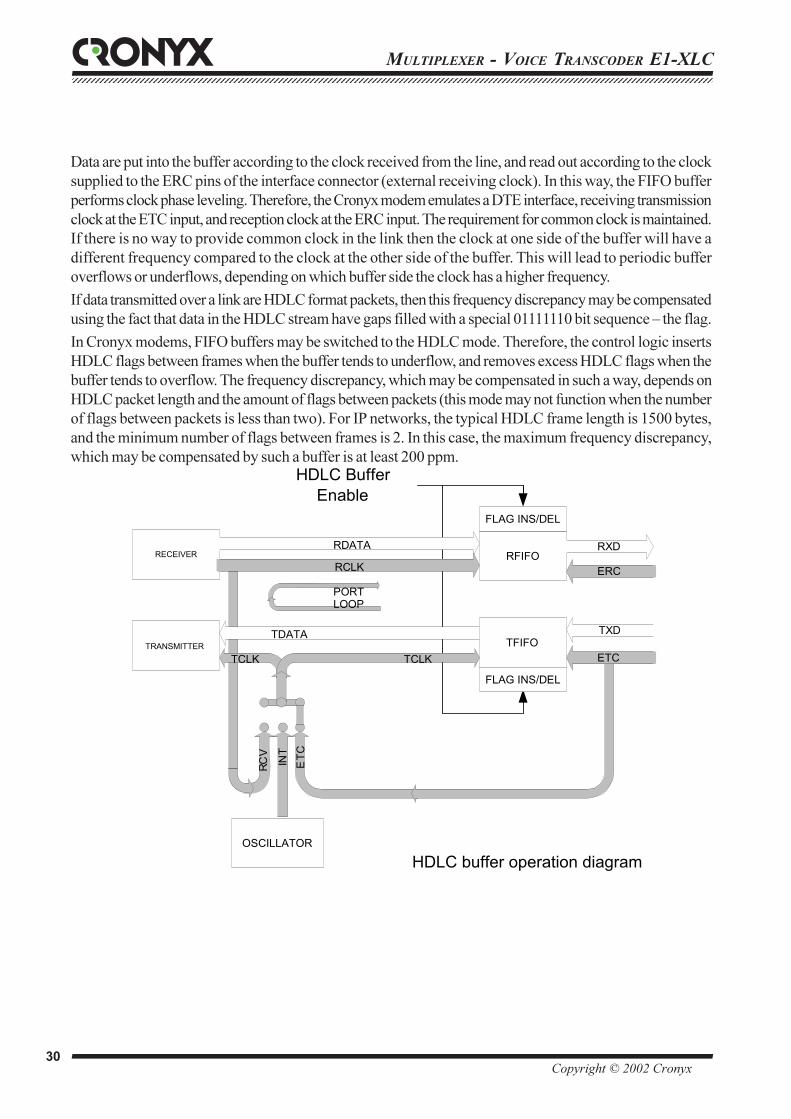
Data are put into the buffer according to the clock received from the line, and read out according to the clock
supplied to the ERC pins of the interface connector (external receiving clock). In this way, the FIFO buffer
performs clock phase leveling. Therefore, the Cronyx modem emulates a DTE interface, receiving transmission
clock at the ETC input, and reception clock at the ERC input. The requirement for common clock is maintained.
If there is no way to provide common clock in the link then the clock at one side of the buffer will have a
different frequency compared to the clock at the other side of the buffer. This will lead to periodic buffer
overflows or underflows, depending on which buffer side the clock has a higher frequency.
If data transmitted over a link are HDLC format packets, then this frequency discrepancy may be compensated
using the fact that data in the HDLC stream have gaps filled with a special 01111110 bit sequence – the flag.
In Cronyx modems, FIFO buffers may be switched to the HDLC mode. Therefore, the control logic inserts
HDLC flags between frames when the buffer tends to underflow, and removes excess HDLC flags when the
buffer tends to overflow. The frequency discrepancy, which may be compensated in such a way, depends on
HDLC packet length and the amount of flags between packets (this mode may not function when the number
of flags between packets is less than two). For IP networks, the typical HDLC frame length is 1500 bytes,
and the minimum number of flags between frames is 2. In this case, the maximum frequency discrepancy,
which may be compensated by such a buffer is at least 200 ppm.
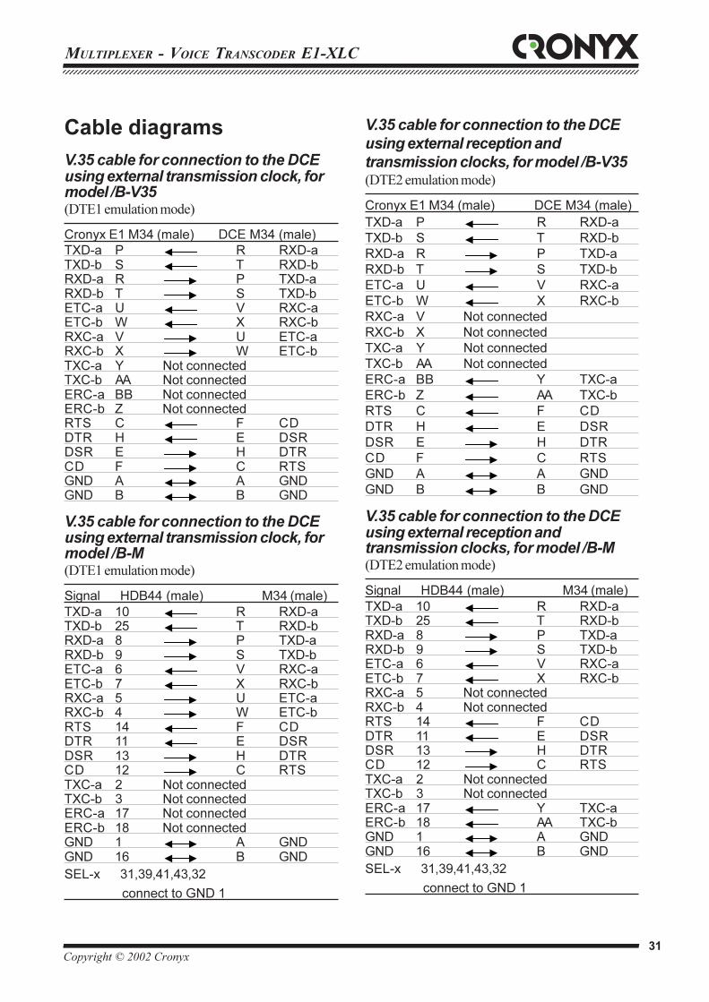
12345678901234567890123456789012123456789012345678901234567890121234567890123456789012345678901212345678901234567890123456789012123456789012345671234567890123456789012345678901212345678901234567890123456789012123456789012345678901234567890121234567890123456789012345678901212345678901234567
Copyright © 2002 Cronyx 31
MULTIPLEXER - VOICE TRANSCODER E1-XLC
Cable diagrams
V.35 cable for connection to the DCEusing external transmission clock, formodel /B-V35(DTE1 emulation mode)
Cronyx Å1 M34 (male) DCE M34 (male)
TXD-a P R RXD-aTXD-b S T RXD-bRXD-a R P TXD-aRXD-b T S TXD-bETC-a U V RXC-aETC-b W X RXC-bRXC-a V U ETC-aRXC-b X W ETC-bTXC-a Y Not connectedTXC-b AA Not connectedERC-a BB Not connectedERC-b Z Not connectedRTS C F CDDTR H E DSRDSR E H DTRCD F C RTSGND A A GNDGND B B GND
V.35 cable for connection to the DCEusing external transmission clock, formodel /B-M(DTE1 emulation mode)
Signal HDB44 (male) M34 (male)
TXD-a 10 R RXD-aTXD-b 25 T RXD-bRXD-a 8 P TXD-aRXD-b 9 S TXD-bETC-a 6 V RXC-aETC-b 7 X RXC-bRXC-a 5 U ETC-aRXC-b 4 W ETC-bRTS 14 F CDDTR 11 E DSRDSR 13 H DTRCD 12 C RTSTXC-a 2 Not connectedTXC-b 3 Not connectedERC-a 17 Not connectedERC-b 18 Not connectedGND 1 A GNDGND 16 B GND
SEL-x 31,39,41,43,32
connect to GND 1
V.35 cable for connection to the DCE
using external reception and
transmission clocks, for model /B-V35(DTE2 emulation mode)
Cronyx Å1 M34 (male) DCE M34 (male)
TXD-a P R RXD-a
TXD-b S T RXD-b
RXD-a R P TXD-a
RXD-b T S TXD-b
ETC-a U V RXC-a
ETC-b W X RXC-b
RXC-a V Not connected
RXC-b X Not connected
TXC-a Y Not connected
TXC-b AA Not connected
ERC-a BB Y TXC-a
ERC-b Z AA TXC-b
RTS C F CD
DTR H E DSR
DSR E H DTR
CD F C RTS
GND A A GND
GND B B GND
V.35 cable for connection to the DCEusing external reception andtransmission clocks, for model /B-M(DTE2 emulation mode)
Signal HDB44 (male) M34 (male)
TXD-a 10 R RXD-aTXD-b 25 T RXD-bRXD-a 8 P TXD-aRXD-b 9 S TXD-bETC-a 6 V RXC-aETC-b 7 X RXC-bRXC-a 5 Not connectedRXC-b 4 Not connectedRTS 14 F CDDTR 11 E DSRDSR 13 H DTRCD 12 C RTSTXC-a 2 Not connectedTXC-b 3 Not connectedERC-a 17 Y TXC-aERC-b 18 AA TXC-bGND 1 A GNDGND 16 B GND
SEL-x 31,39,41,43,32
connect to GND 1
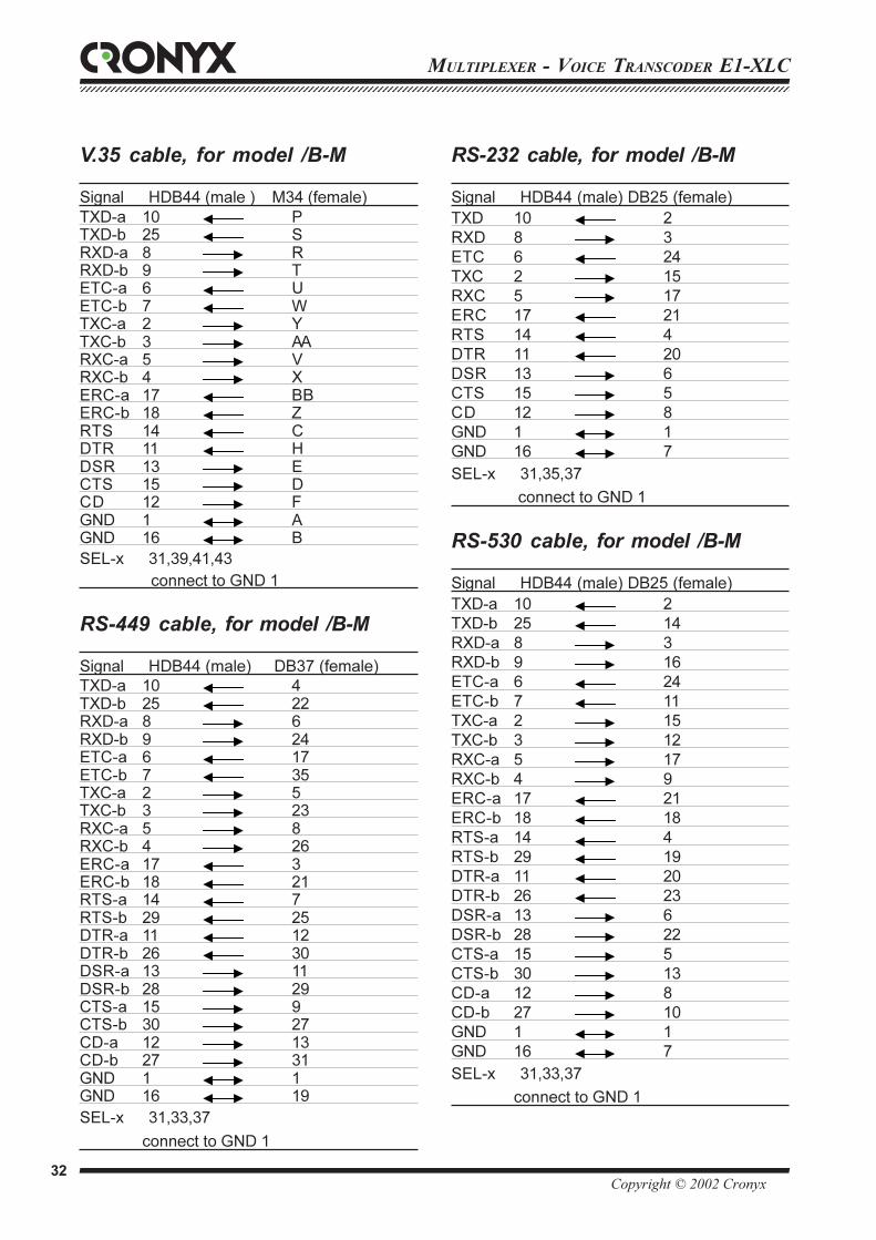
MULTIPLEXER - VOICE TRANSCODER E1-XLC123456789012345678901234567890121234567890123456789012345678901212345678901234567890123456789012123456789012345678901234567890121234567890123456123456789012345678901234567890121234567890123456789012345678901212345678901234567890123456789012123456789012345678901234567890121234567890123456
Copyright © 2002 Cronyx 32
RS-232 cable, for model /B-M
Signal HDB44 (male) DB25 (female)
TXD 10 2
RXD 8 3
ETC 6 24
TXC 2 15
RXC 5 17
ERC 17 21
RTS 14 4
DTR 11 20
DSR 13 6
CTS 15 5
CD 12 8
GND 1 1
GND 16 7
SEL-x 31,35,37
connect to GND 1
RS-530 cable, for model /B-M
Signal HDB44 (male) DB25 (female)
TXD-a 10 2
TXD-b 25 14
RXD-a 8 3
RXD-b 9 16
ETC-a 6 24
ETC-b 7 11
TXC-a 2 15
TXC-b 3 12
RXC-a 5 17
RXC-b 4 9
ERC-a 17 21
ERC-b 18 18
RTS-a 14 4
RTS-b 29 19
DTR-a 11 20
DTR-b 26 23
DSR-a 13 6
DSR-b 28 22
CTS-a 15 5
CTS-b 30 13
CD-a 12 8
CD-b 27 10
GND 1 1
GND 16 7
SEL-x 31,33,37
connect to GND 1
V.35 cable, for model /B-M
Signal HDB44 (male ) M34 (female)
TXD-a 10 PTXD-b 25 SRXD-a 8 RRXD-b 9 TETC-a 6 UETC-b 7 WTXC-a 2 YTXC-b 3 AARXC-a 5 VRXC-b 4 XERC-a 17 BBERC-b 18 ZRTS 14 CDTR 11 HDSR 13 ECTS 15 DCD 12 FGND 1 AGND 16 B
SEL-x 31,39,41,43
connect to GND 1
RS-449 cable, for model /B-M
Signal HDB44 (male) DB37 (female)
TXD-a 10 4TXD-b 25 22RXD-a 8 6RXD-b 9 24ETC-a 6 17ETC-b 7 35TXC-a 2 5TXC-b 3 23RXC-a 5 8RXC-b 4 26ERC-a 17 3ERC-b 18 21RTS-a 14 7RTS-b 29 25DTR-a 11 12DTR-b 26 30DSR-a 13 11DSR-b 28 29CTS-a 15 9CTS-b 30 27CD-a 12 13CD-b 27 31GND 1 1GND 16 19
SEL-x 31,33,37
connect to GND 1
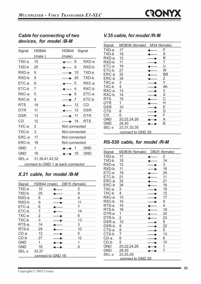
12345678901234567890123456789012123456789012345678901234567890121234567890123456789012345678901212345678901234567890123456789012123456789012345671234567890123456789012345678901212345678901234567890123456789012123456789012345678901234567890121234567890123456789012345678901212345678901234567
Copyright © 2002 Cronyx 33
MULTIPLEXER - VOICE TRANSCODER E1-XLC
Cable for connecting of two
devices, for model /B-M
Signal HDB44 HDB44 Signal
(male ) (male)
TXD-a 10 8 RXD-a
TXD-b 25 9 RXD-b
RXD-a 8 10 TXD-a
RXD-b 9 25 TXD-b
ETC-a 6 5 RXC-a
ETC-b 7 4 RXC-b
RXC-a 5 6 ETC-a
RXC-b 4 7 ETC-b
RTS 14 12 CD
DTR 11 13 DSR
DSR 13 11 DTR
CD 12 14 RTS
TXC-a 2 Not connected
TXC-b 3 Not connected
ERC-a 17 Not connected
ERC-b 18 Not connected
GND 1 1 GND
GND 16 16 GND
SEL-x 31,39,41,43,32
connect to GND 1 at each connector
X.21 cable, for model /B-M
Signal HDB44 (male) DB15 (female)
TXD-a 10 2
TXD-b 25 9
RXD-a 8 4
RXD-b 9 11
ETC-a 6 7
ETC-b 7 14
TXC-a 2 6
TXC-b 3 13
RTS-a 14 3
RTS-b 29 10
CD-a 12 5
CD-b 27 12
GND 1 1
GND 16 8
SEL-x 33,37
connect to GND 16
V.35 cable, for model /R-M
Signal MDB36 (female) M34 (female)
TXD-a 17 PTXD-b 18 SRXD-a 12 RRXD-b 11 TETC-a 19 UETC-b 21 WERC-a 32 BBERC-b 34 ZTXC-a 3 YTXC-b 4 AARXC-a 13 VRXC-b 14 XRTS 15 CDTR 1 HDSR 10 ECTS 8 DCD 6 FGND 20,22,24,26 AGND 28,30 BSEL-x 23,31,33,35
connect to GND 28
RS-530 cable, for model /R-M
Signal MDB36 (female) DB25 (female)
TXD-a 17 2TXD-b 18 14RXD-a 12 3RXD-b 11 16ETC-a 19 24ETC-b 21 11ERC-a 32 21ERC-b 34 18TXC-a 3 15TXC-b 4 12RXC-a 13 17RXC-b 14 9RTS-a 15 4RTS-b 16 19DTR-a 1 20DTR-b 2 23DSR-a 10 6DSR-b 9 22CTS-a 8 5CTS-b 7 13CD-a 6 8CD-b 5 10GND 20,22,24,26 1GND 28,30 7SEL-x 23,25,29
connect to GND 28
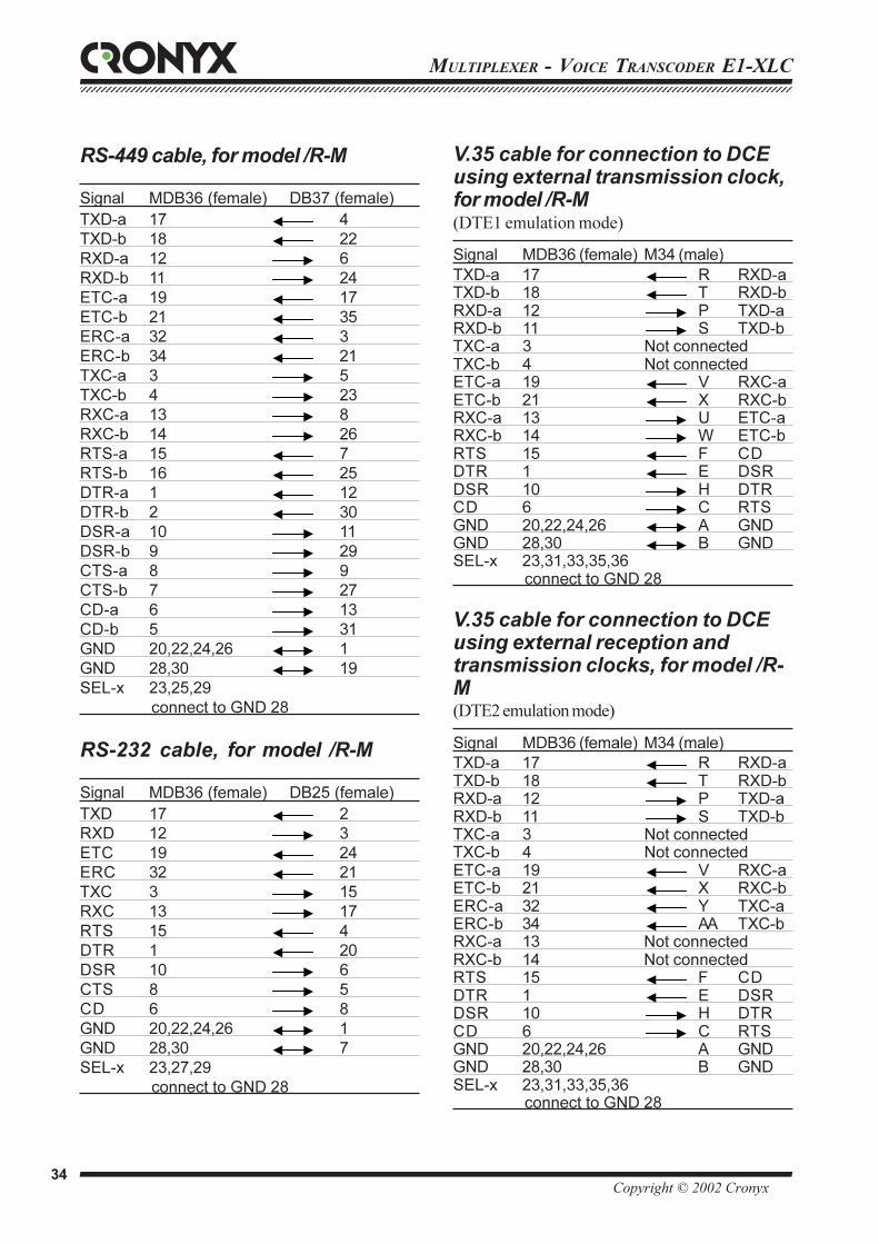
MULTIPLEXER - VOICE TRANSCODER E1-XLC123456789012345678901234567890121234567890123456789012345678901212345678901234567890123456789012123456789012345678901234567890121234567890123456123456789012345678901234567890121234567890123456789012345678901212345678901234567890123456789012123456789012345678901234567890121234567890123456
Copyright © 2002 Cronyx 34
RS-449 cable, for model /R-M
Signal MDB36 (female) DB37 (female)
TXD-a 17 4
TXD-b 18 22
RXD-a 12 6
RXD-b 11 24
ETC-a 19 17
ETC-b 21 35
ERC-a 32 3
ERC-b 34 21
TXC-a 3 5
TXC-b 4 23
RXC-a 13 8
RXC-b 14 26
RTS-a 15 7
RTS-b 16 25
DTR-a 1 12
DTR-b 2 30
DSR-a 10 11
DSR-b 9 29
CTS-a 8 9
CTS-b 7 27
CD-a 6 13
CD-b 5 31
GND 20,22,24,26 1
GND 28,30 19
SEL-x 23,25,29
connect to GND 28
RS-232 cable, for model /R-M
Signal MDB36 (female) DB25 (female)
TXD 17 2
RXD 12 3
ETC 19 24
ERC 32 21
TXC 3 15
RXC 13 17
RTS 15 4
DTR 1 20
DSR 10 6
CTS 8 5
CD 6 8
GND 20,22,24,26 1
GND 28,30 7
SEL-x 23,27,29
connect to GND 28
V.35 cable for connection to DCEusing external transmission clock,for model /R-M(DTE1 emulation mode)
Signal MDB36 (female) M34 (male)
TXD-a 17 R RXD-aTXD-b 18 T RXD-bRXD-a 12 P TXD-aRXD-b 11 S TXD-bTXC-a 3 Not connectedTXC-b 4 Not connectedETC-a 19 V RXC-aETC-b 21 X RXC-bRXC-a 13 U ETC-aRXC-b 14 W ETC-bRTS 15 F CDDTR 1 E DSRDSR 10 H DTRCD 6 C RTSGND 20,22,24,26 A GNDGND 28,30 B GNDSEL-x 23,31,33,35,36
connect to GND 28
V.35 cable for connection to DCEusing external reception andtransmission clocks, for model /R-M(DTE2 emulation mode)
Signal MDB36 (female) M34 (male)
TXD-a 17 R RXD-aTXD-b 18 T RXD-bRXD-a 12 P TXD-aRXD-b 11 S TXD-bTXC-a 3 Not connectedTXC-b 4 Not connectedETC-a 19 V RXC-aETC-b 21 X RXC-bERC-a 32 Y TXC-aERC-b 34 AA TXC-bRXC-a 13 Not connectedRXC-b 14 Not connectedRTS 15 F CDDTR 1 E DSRDSR 10 H DTRCD 6 C RTSGND 20,22,24,26 A GNDGND 28,30 B GNDSEL-x 23,31,33,35,36
connect to GND 28
12345678901234567890123456789012123456789012345678901234567890121234567890123456789012345678901212345678901234567890123456789012123456789012345671234567890123456789012345678901212345678901234567890123456789012123456789012345678901234567890121234567890123456789012345678901212345678901234567
Copyright © 2002 Cronyx 35
MULTIPLEXER - VOICE TRANSCODER E1-XLC
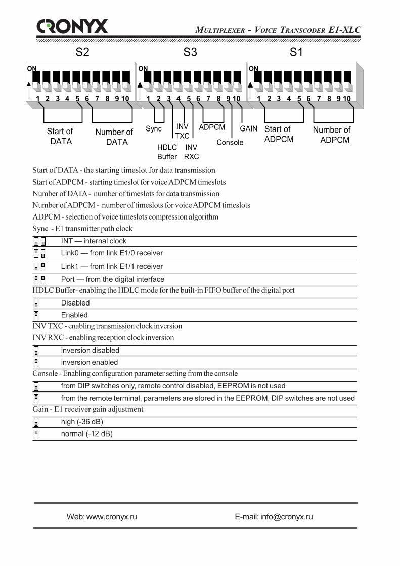
MULTIPLEXER - VOICE TRANSCODER E1-XLC123456789012345678901234567890121234567890123456789012345678901212345678901234567890123456789012123456789012345678901234567890121234567890123456123456789012345678901234567890121234567890123456789012345678901212345678901234567890123456789012123456789012345678901234567890121234567890123456
123456789012345678901234567890121234567890123456789012345678901212345678901234567890123456789012123456789012345678901234567890121234567890123456123456789012345678901234567890121234567890123456789012345678901212345678901234567890123456789012123456789012345678901234567890121234567890123456
ON
1 2 3 4 5 6 10987
Start ofDATA
Number ofDATA
ON
1 2 3 4 5 6 10987
Sync
HDLCBuffer
INVRXC
ADPCM
Console
GAIN
ON
1 2 3 4 5 6 10987
Start ofADPCM
Number ofADPCM
S1S3S2
INVTXC
Start of DATA - the starting timeslot for data transmission
Start of ADPCM - starting timeslot for voice ADPCM timeslots
Number of DATA - number of timeslots for data transmission
Number of ADPCM - number of timeslots for voice ADPCM timeslots
ADPCM - selection of voice timeslots compression algorithm
Sync - E1 transmitter path clock
INT — internal clock
Link0 — from link E1/0 receiver
Link1 — from link E1/1 receiver
Port — from the digital interface
HDLC Buffer- enabling the HDLC mode for the built-in FIFO buffer of the digital port
Disabled
Enabled
INV TXC - enabling transmission clock inversion
INV RXC - enabling reception clock inversion
inversion disabled
inversion enabled
Console - Enabling configuration parameter setting from the console
from DIP switches only, remote control disabled, EEPROM is not used
from the remote terminal, parameters are stored in the EEPROM, DIP switches are not used
Gain - E1 receiver gain adjustment
high (-36 dB)
normal (-12 dB)
Web: www.cronyx.ru E-mail: [email protected]