multiplex communication – multiplex...
TRANSCRIPT
MULTIPLEX COMMUNICATION – MULTIPLEX COMMUNICATION SYSTEM MP–1
MP
MULTIPLEX COMMUNICATION SYSTEMPRECAUTIONNOTICE:• When disconnecting the cable from the negative (-)
battery terminal, initialize the following system after the cable is reconnected.
• When the warning light is illuminated or the battery has been disconnected, pressing the power switch may not start the system on the first try. If so, press the power switch again.
System Name See Procedure
Power Window Control System IN-32
MP–2 MULTIPLEX COMMUNICATION – MULTIPLEX COMMUNICATION SYSTEM
MP
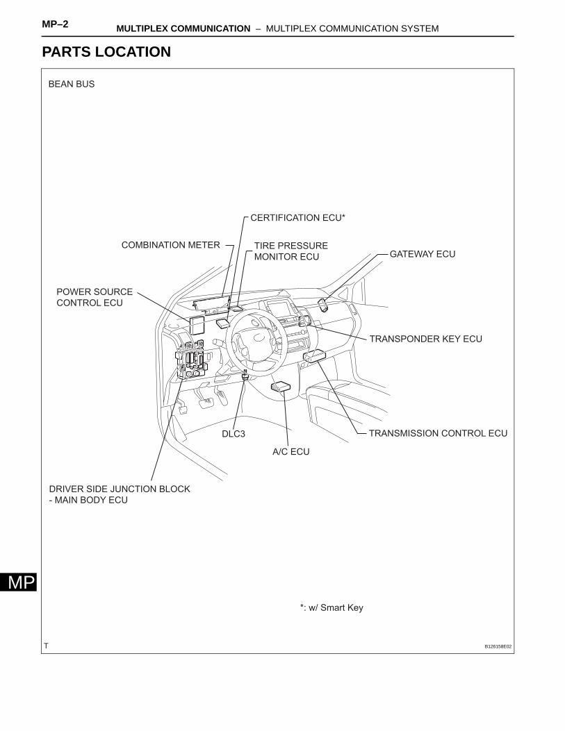
PARTS LOCATION
POWER SOURCE
CONTROL ECU
COMBINATION METER
CERTIFICATION ECU*
GATEWAY ECU
TRANSPONDER KEY ECU
TRANSMISSION CONTROL ECU
A/C ECU
DLC3
DRIVER SIDE JUNCTION BLOCK
- MAIN BODY ECU
*: w/ Smart Key
BEAN BUS
TIRE PRESSURE
MONITOR ECU
B126158E02
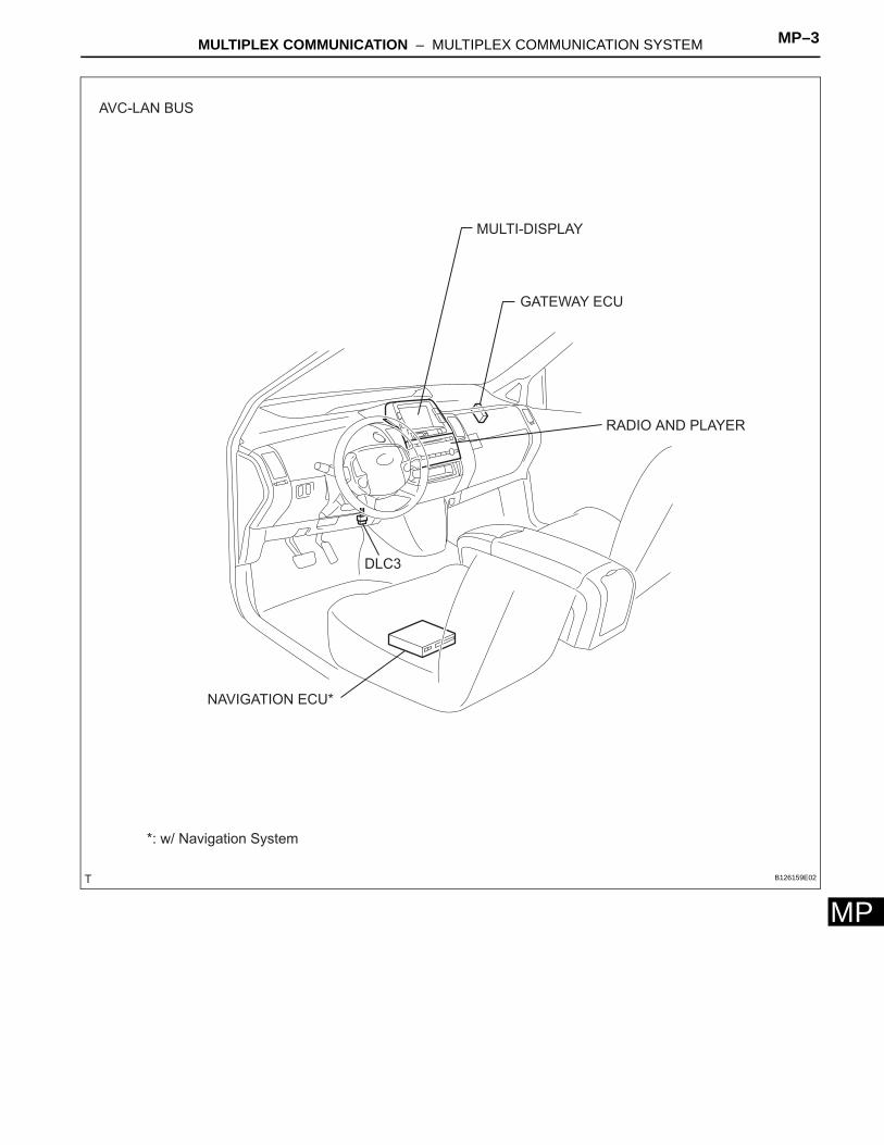
MULTIPLEX COMMUNICATION – MULTIPLEX COMMUNICATION SYSTEM MP–3
MP
MULTI-DISPLAY
GATEWAY ECU
NAVIGATION ECU*
*: w/ Navigation System
RADIO AND PLAYER
DLC3
AVC-LAN BUS
B126159E02
MP–4 MULTIPLEX COMMUNICATION – MULTIPLEX COMMUNICATION SYSTEM
MP
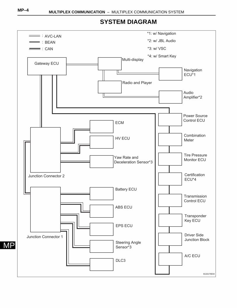
SYSTEM DIAGRAM
:
:
:
AVC-LAN
BEAN
CAN
*1: w/ Navigation
*2: w/ JBL Audio
*3: w/ VSC
*4: w/ Smart Key
Gateway ECU
Multi-display
Radio and Player
Navigation
ECU*1
Audio
Amplifier*2
Junction Connector 2
Junction Connector 1
ECM
HV ECU
Yaw Rate and
Deceleration Sensor*3
Battery ECU
ABS ECU
EPS ECU
Steering Angle
Sensor*3
DLC3
Power Source
Control ECU
Combination
Meter
Tire Pressure
Monitor ECU
Certification
ECU*4
Transmission
Control ECU
Transponder
Key ECU
Driver Side
Junction Block
A/C ECU
B133175E04
MULTIPLEX COMMUNICATION – MULTIPLEX COMMUNICATION SYSTEM MP–5
MP
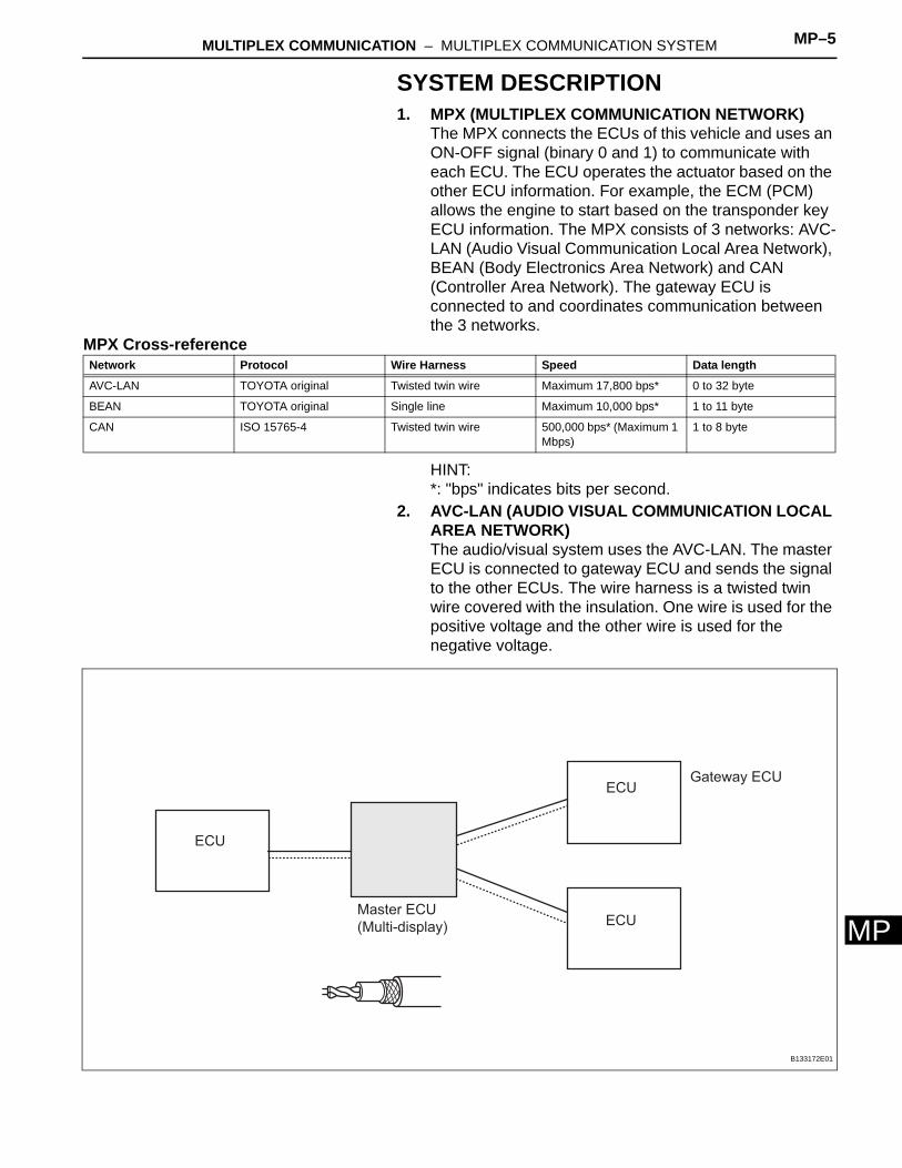
SYSTEM DESCRIPTION1. MPX (MULTIPLEX COMMUNICATION NETWORK)
The MPX connects the ECUs of this vehicle and uses an ON-OFF signal (binary 0 and 1) to communicate with each ECU. The ECU operates the actuator based on the other ECU information. For example, the ECM (PCM) allows the engine to start based on the transponder key ECU information. The MPX consists of 3 networks: AVC-LAN (Audio Visual Communication Local Area Network), BEAN (Body Electronics Area Network) and CAN (Controller Area Network). The gateway ECU is connected to and coordinates communication between the 3 networks.
MPX Cross-reference
HINT:*: "bps" indicates bits per second.
2. AVC-LAN (AUDIO VISUAL COMMUNICATION LOCAL AREA NETWORK)The audio/visual system uses the AVC-LAN. The master ECU is connected to gateway ECU and sends the signal to the other ECUs. The wire harness is a twisted twin wire covered with the insulation. One wire is used for the positive voltage and the other wire is used for the negative voltage.
Network Protocol Wire Harness Speed Data length
AVC-LAN TOYOTA original Twisted twin wire Maximum 17,800 bps* 0 to 32 byte
BEAN TOYOTA original Single line Maximum 10,000 bps* 1 to 11 byte
CAN ISO 15765-4 Twisted twin wire 500,000 bps* (Maximum 1 Mbps)
1 to 8 byte
ECU
ECU
ECU
Gateway ECU
Master ECU
(Multi-display)
B133172E01
MP–6 MULTIPLEX COMMUNICATION – MULTIPLEX COMMUNICATION SYSTEM
MP
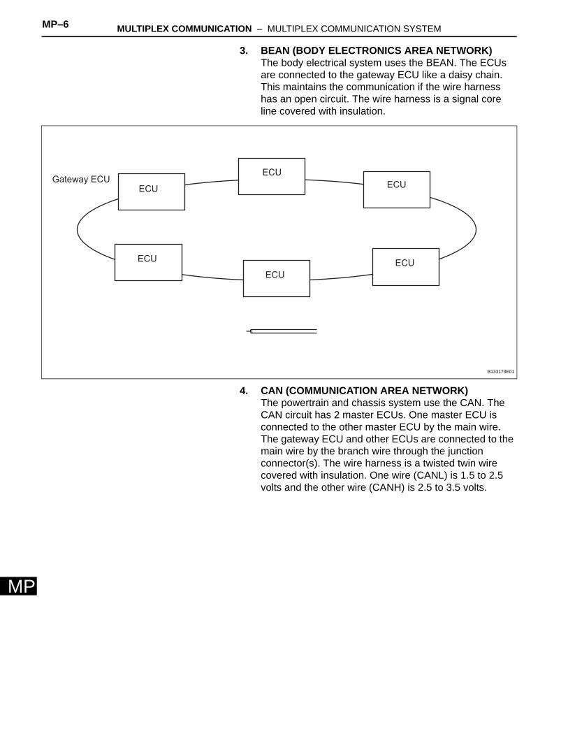
3. BEAN (BODY ELECTRONICS AREA NETWORK)The body electrical system uses the BEAN. The ECUs are connected to the gateway ECU like a daisy chain. This maintains the communication if the wire harness has an open circuit. The wire harness is a signal core line covered with insulation.
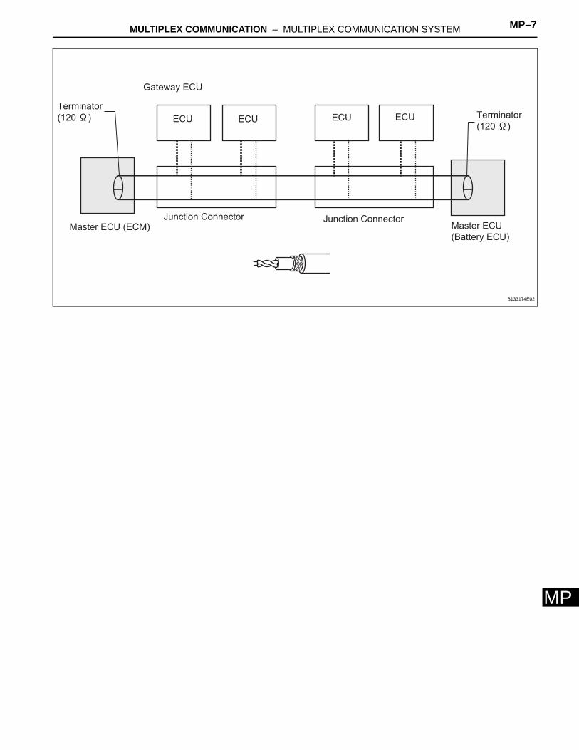
4. CAN (COMMUNICATION AREA NETWORK)The powertrain and chassis system use the CAN. The CAN circuit has 2 master ECUs. One master ECU is connected to the other master ECU by the main wire. The gateway ECU and other ECUs are connected to the main wire by the branch wire through the junction connector(s). The wire harness is a twisted twin wire covered with insulation. One wire (CANL) is 1.5 to 2.5 volts and the other wire (CANH) is 2.5 to 3.5 volts.
Gateway ECU
ECU
ECU
ECU
ECU
ECU
ECU
B133173E01
MULTIPLEX COMMUNICATION – MULTIPLEX COMMUNICATION SYSTEM MP–7
MP
ECU ECU ECU ECU
Gateway ECU
Junction Connector Junction ConnectorMaster ECU (ECM) Master ECU
(Battery ECU)
Terminator
(120 ) Terminator
(120 )
B133174E02
MP–8 MULTIPLEX COMMUNICATION – MULTIPLEX COMMUNICATION SYSTEM
MP
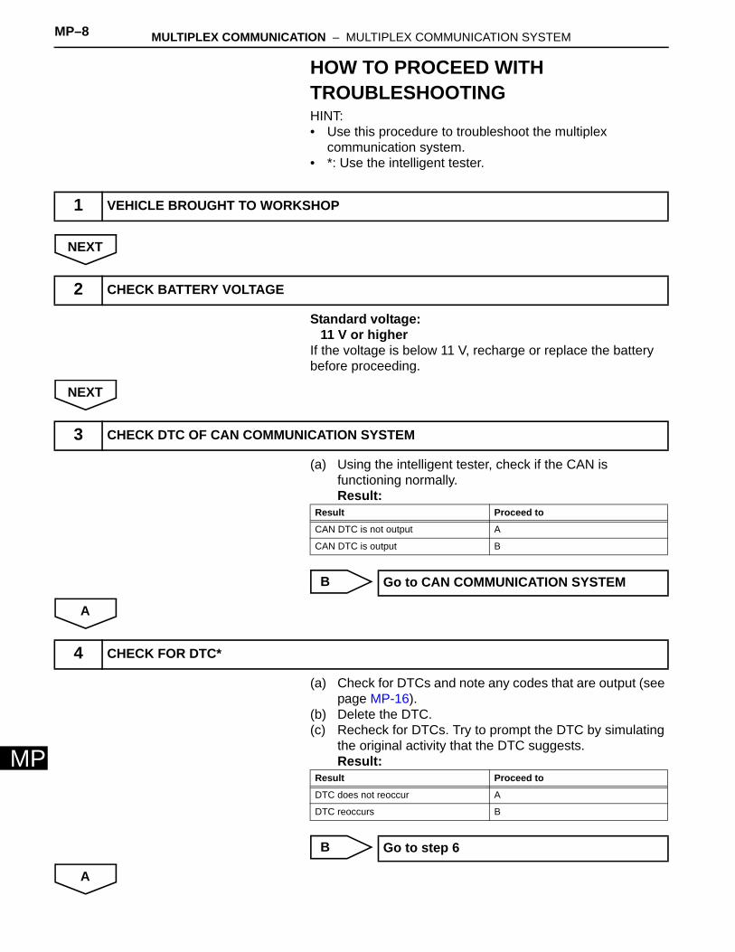
HOW TO PROCEED WITH TROUBLESHOOTINGHINT:• Use this procedure to troubleshoot the multiplex
communication system.• *: Use the intelligent tester.
NEXT
Standard voltage:11 V or higher
If the voltage is below 11 V, recharge or replace the battery before proceeding.
NEXT
(a) Using the intelligent tester, check if the CAN is functioning normally.Result:
B
A
(a) Check for DTCs and note any codes that are output (see page MP-16).
(b) Delete the DTC.(c) Recheck for DTCs. Try to prompt the DTC by simulating
the original activity that the DTC suggests.Result:
B
A
1 VEHICLE BROUGHT TO WORKSHOP
2 CHECK BATTERY VOLTAGE
3 CHECK DTC OF CAN COMMUNICATION SYSTEM
Result Proceed to
CAN DTC is not output A
CAN DTC is output B
Go to CAN COMMUNICATION SYSTEM
4 CHECK FOR DTC*
Result Proceed to
DTC does not reoccur A
DTC reoccurs B
Go to step 6

MULTIPLEX COMMUNICATION – MULTIPLEX COMMUNICATION SYSTEM MP–9
MP
(a) Terminals of ECU (see page MP-9).
NEXT
NEXT
NEXT
5 OVERALL ANALYSIS AND TROUBLESHOOTING
6 ADJUST, REPAIR OR REPLACE
7 CONFIRMATION TEST
END
MP–10 MULTIPLEX COMMUNICATION – MULTIPLEX COMMUNICATION SYSTEM
MP
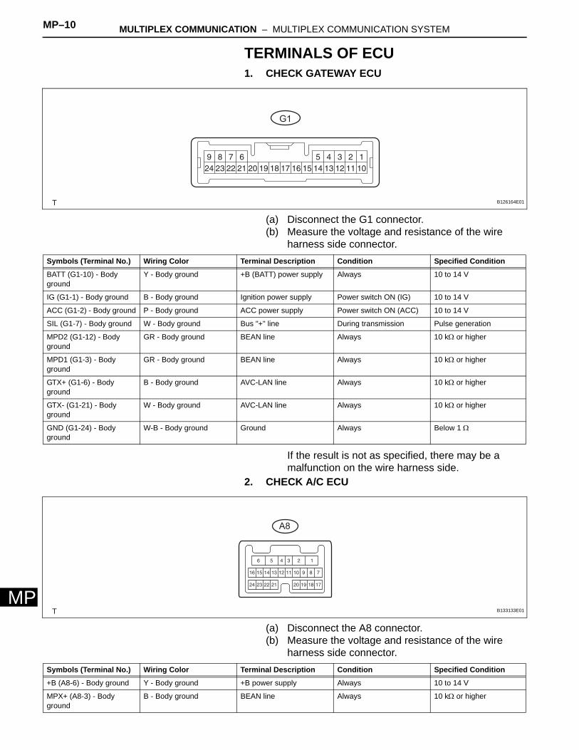
TERMINALS OF ECU1. CHECK GATEWAY ECU
(a) Disconnect the G1 connector.(b) Measure the voltage and resistance of the wire
harness side connector.
If the result is not as specified, there may be a malfunction on the wire harness side.
2. CHECK A/C ECU
(a) Disconnect the A8 connector.(b) Measure the voltage and resistance of the wire
harness side connector.
G1
B126164E01
Symbols (Terminal No.) Wiring Color Terminal Description Condition Specified Condition
BATT (G1-10) - Body ground
Y - Body ground +B (BATT) power supply Always 10 to 14 V
IG (G1-1) - Body ground B - Body ground Ignition power supply Power switch ON (IG) 10 to 14 V
ACC (G1-2) - Body ground P - Body ground ACC power supply Power switch ON (ACC) 10 to 14 V
SIL (G1-7) - Body ground W - Body ground Bus "+" line During transmission Pulse generation
MPD2 (G1-12) - Body ground
GR - Body ground BEAN line Always 10 kΩ or higher
MPD1 (G1-3) - Body ground
GR - Body ground BEAN line Always 10 kΩ or higher
GTX+ (G1-6) - Body ground
B - Body ground AVC-LAN line Always 10 kΩ or higher
GTX- (G1-21) - Body ground
W - Body ground AVC-LAN line Always 10 kΩ or higher
GND (G1-24) - Body ground
W-B - Body ground Ground Always Below 1 Ω
A8
B133133E01
Symbols (Terminal No.) Wiring Color Terminal Description Condition Specified Condition
+B (A8-6) - Body ground Y - Body ground +B power supply Always 10 to 14 V
MPX+ (A8-3) - Body ground
B - Body ground BEAN line Always 10 kΩ or higher
MULTIPLEX COMMUNICATION – MULTIPLEX COMMUNICATION SYSTEM MP–11
MP
If the result is not as specified, there may be a malfunction on the wire harness side.
MPX2+ (A8-11) - Body ground
GR - Body ground BEAN line Always 10 kΩ or higher
GND (A8-1) - Body ground W-B - Body ground Ground Always Below 1 Ω
Symbols (Terminal No.) Wiring Color Terminal Description Condition Specified Condition
MP–12 MULTIPLEX COMMUNICATION – MULTIPLEX COMMUNICATION SYSTEM
MP
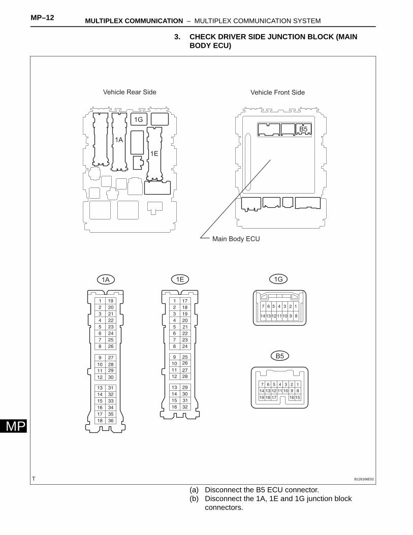
3. CHECK DRIVER SIDE JUNCTION BLOCK (MAIN BODY ECU)
(a) Disconnect the B5 ECU connector.(b) Disconnect the 1A, 1E and 1G junction block
connectors.
Vehicle Rear Side
1G
1E
1A
Vehicle Front Side
B5
Main Body ECU
1A 1E 1G
B5
B126166E02
MULTIPLEX COMMUNICATION – MULTIPLEX COMMUNICATION SYSTEM MP–13
MP
(c) Measure the voltage and resistance of the wire harness side connectors.
If the result is not as specified, there may be a malfunction on the wire harness side.
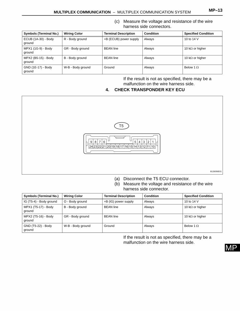
4. CHECK TRANSPONDER KEY ECU
(a) Disconnect the T5 ECU connector.(b) Measure the voltage and resistance of the wire
harness side connector.
If the result is not as specified, there may be a malfunction on the wire harness side.
Symbols (Terminal No.) Wiring Color Terminal Description Condition Specified Condition
ECUB (1A-30) - Body ground
R - Body ground +B (ECUB) power supply Always 10 to 14 V
MPX1 (1G-9) - Body ground
GR - Body ground BEAN line Always 10 kΩ or higher
MPX2 (B5-15) - Body ground
B - Body ground BEAN line Always 10 kΩ or higher
GND (1E-17) - Body ground
W-B - Body ground Ground Always Below 1 Ω
1
10
2
11
3
12
4
13
5
14
6
21
7
22
8
23
9
24 151617181920
T5
B126056E01
Symbols (Terminal No.) Wiring Color Terminal Description Condition Specified Condition
IG (T5-4) - Body ground O - Body ground +B (IG) power supply Always 10 to 14 V
MPX1 (T5-17) - Body ground
B - Body ground BEAN line Always 10 kΩ or higher
MPX2 (T5-16) - Body ground
GR - Body ground BEAN line Always 10 kΩ or higher
GND (T5-22) - Body ground
W-B - Body ground Ground Always Below 1 Ω

MP–14 MULTIPLEX COMMUNICATION – MULTIPLEX COMMUNICATION SYSTEM
MP
5. CHECK TRANSMISSION CONTROL ECU
(a) Disconnect the T4 ECU connector.(b) Measure the voltage and resistance of the wire
harness side connector.
If the result is not as specified, there may be a malfunction on the wire harness side.
6. CHECK CERTIFICATION ECU (WITH SMART KEY)
(a) Disconnect the S11 ECU connector.(b) Measure the voltage and resistance of the wire
harness side connector.
If the result is not as specified, there may be a malfunction on the wire harness side.
T4
B126167E01
Symbols (Terminal No.) Wiring Color Terminal Description Condition Specified Condition
+B (T4-1) - Body ground L - Body ground +B power supply Always 10 to 14 V
MPX1 (T4-19) - Body ground
GR - Body ground BEAN line Always 10 kΩ or higher
MPX2 (T4-18) - Body ground
B - Body ground BEAN line Always 10 kΩ or higher
E1 (T4-15) - Body ground W-B - Body ground Ground Always Below 1 Ω
1
18
2
19
3
20
4
21
5
22
6
23
7
24
8
25
9
26
10
33
11
34
12
35
13
36
14
37
15
38
16
39
17
40 272829303132
S11
B126057E01
Symbols (Terminal No.) Wiring Color Terminal Description Condition Specified Condition
+B1 (S11-1) - Body ground
R - Body ground +B power supply Always 10 to 14 V
MPX1 (S11-31) - Body ground
GR - Body ground BEAN line Always 10 kΩ or higher
MPX2 (S11-32) - Body ground
B - Body ground BEAN line Always 10 kΩ or higher
E (S11-17) - Body ground W-B - Body ground Ground Always Below 1 Ω
MULTIPLEX COMMUNICATION – MULTIPLEX COMMUNICATION SYSTEM MP–15
MP
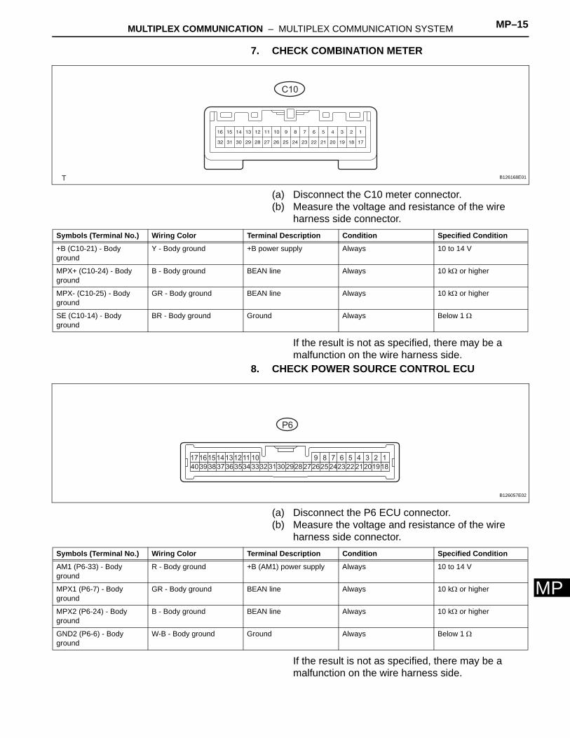
7. CHECK COMBINATION METER
(a) Disconnect the C10 meter connector.(b) Measure the voltage and resistance of the wire
harness side connector.
If the result is not as specified, there may be a malfunction on the wire harness side.
8. CHECK POWER SOURCE CONTROL ECU
(a) Disconnect the P6 ECU connector.(b) Measure the voltage and resistance of the wire
harness side connector.
If the result is not as specified, there may be a malfunction on the wire harness side.
C10
B126168E01
Symbols (Terminal No.) Wiring Color Terminal Description Condition Specified Condition
+B (C10-21) - Body ground
Y - Body ground +B power supply Always 10 to 14 V
MPX+ (C10-24) - Body ground
B - Body ground BEAN line Always 10 kΩ or higher
MPX- (C10-25) - Body ground
GR - Body ground BEAN line Always 10 kΩ or higher
SE (C10-14) - Body ground
BR - Body ground Ground Always Below 1 Ω
1
18
2
19
3
20
4
21
5
22
6
23
7
24
8
25
9
26
10
33
11
34
12
35
13
36
14
37
15
38
16
39
17
40 272829303132
P6
B126057E02
Symbols (Terminal No.) Wiring Color Terminal Description Condition Specified Condition
AM1 (P6-33) - Body ground
R - Body ground +B (AM1) power supply Always 10 to 14 V
MPX1 (P6-7) - Body ground
GR - Body ground BEAN line Always 10 kΩ or higher
MPX2 (P6-24) - Body ground
B - Body ground BEAN line Always 10 kΩ or higher
GND2 (P6-6) - Body ground
W-B - Body ground Ground Always Below 1 Ω
MP–16 MULTIPLEX COMMUNICATION – MULTIPLEX COMMUNICATION SYSTEM
MP
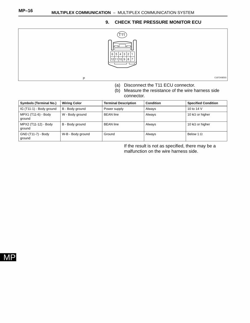
9. CHECK TIRE PRESSURE MONITOR ECU
(a) Disconnect the T11 ECU connector.(b) Measure the resistance of the wire harness side
connector.
If the result is not as specified, there may be a malfunction on the wire harness side.
T11
C107243E03
Symbols (Terminal No.) Wiring Color Terminal Description Condition Specified Condition
IG (T11-1) - Body ground B - Body ground Power supply Always 10 to 14 V
MPX1 (T11-6) - Body ground
W - Body ground BEAN line Always 10 kΩ or higher
MPX2 (T11-12) - Body ground
B - Body ground BEAN line Always 10 kΩ or higher
GND (T11-7) - Body ground
W-B - Body ground Ground Always Below 1 Ω
MULTIPLEX COMMUNICATION – MULTIPLEX COMMUNICATION SYSTEM MP–17
MP
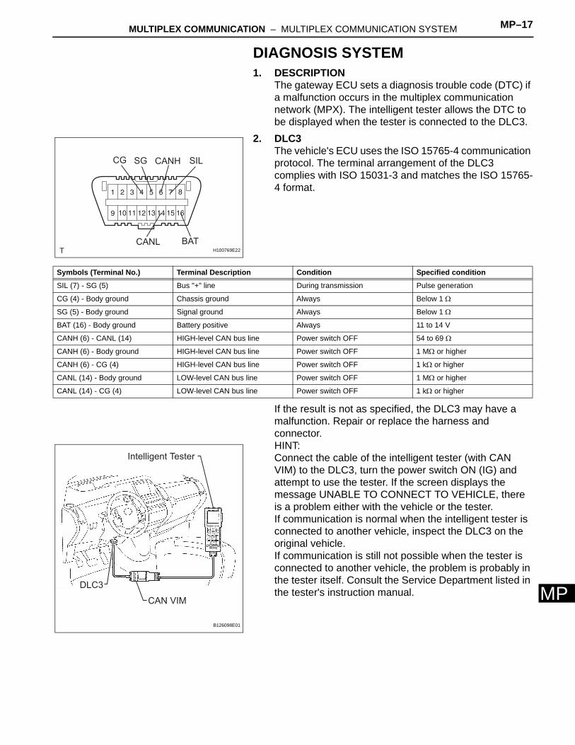
DIAGNOSIS SYSTEM1. DESCRIPTION
The gateway ECU sets a diagnosis trouble code (DTC) if a malfunction occurs in the multiplex communication network (MPX). The intelligent tester allows the DTC to be displayed when the tester is connected to the DLC3.
2. DLC3The vehicle's ECU uses the ISO 15765-4 communication protocol. The terminal arrangement of the DLC3 complies with ISO 15031-3 and matches the ISO 15765-4 format.
If the result is not as specified, the DLC3 may have a malfunction. Repair or replace the harness and connector.HINT:Connect the cable of the intelligent tester (with CAN VIM) to the DLC3, turn the power switch ON (IG) and attempt to use the tester. If the screen displays the message UNABLE TO CONNECT TO VEHICLE, there is a problem either with the vehicle or the tester.If communication is normal when the intelligent tester is connected to another vehicle, inspect the DLC3 on the original vehicle.If communication is still not possible when the tester is connected to another vehicle, the problem is probably in the tester itself. Consult the Service Department listed in the tester's instruction manual.
CG SG
BAT
SILCANH
CANLH100769E22
Symbols (Terminal No.) Terminal Description Condition Specified condition
SIL (7) - SG (5) Bus "+" line During transmission Pulse generation
CG (4) - Body ground Chassis ground Always Below 1 Ω
SG (5) - Body ground Signal ground Always Below 1 Ω
BAT (16) - Body ground Battery positive Always 11 to 14 V
CANH (6) - CANL (14) HIGH-level CAN bus line Power switch OFF 54 to 69 Ω
CANH (6) - Body ground HIGH-level CAN bus line Power switch OFF 1 MΩ or higher
CANH (6) - CG (4) HIGH-level CAN bus line Power switch OFF 1 kΩ or higher
CANL (14) - Body ground LOW-level CAN bus line Power switch OFF 1 MΩ or higher
CANL (14) - CG (4) LOW-level CAN bus line Power switch OFF 1 kΩ or higher
DLC3
CAN VIM
Intelligent Tester
B126098E01
MP–18 MULTIPLEX COMMUNICATION – MULTIPLEX COMMUNICATION SYSTEM
MP
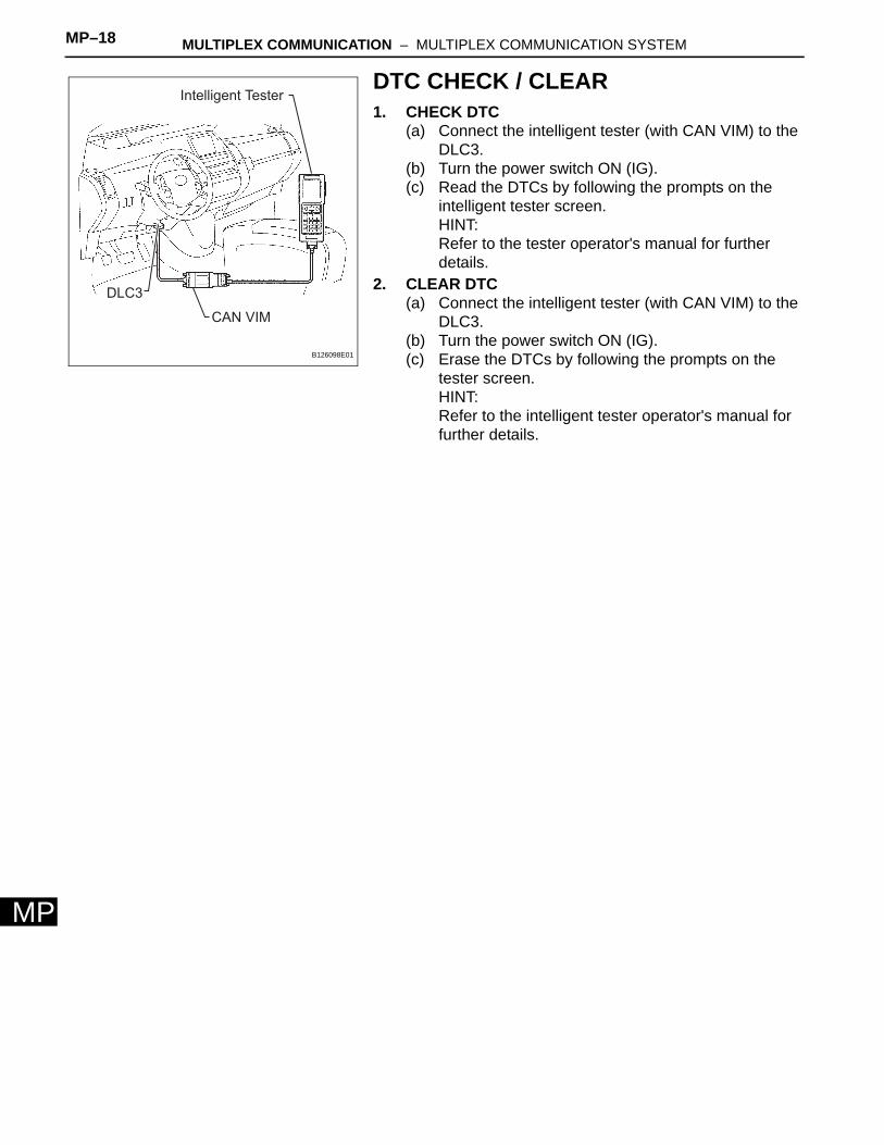
DTC CHECK / CLEAR1. CHECK DTC
(a) Connect the intelligent tester (with CAN VIM) to the DLC3.
(b) Turn the power switch ON (IG).(c) Read the DTCs by following the prompts on the
intelligent tester screen.HINT:Refer to the tester operator's manual for further details.
2. CLEAR DTC(a) Connect the intelligent tester (with CAN VIM) to the
DLC3.(b) Turn the power switch ON (IG).(c) Erase the DTCs by following the prompts on the
tester screen.HINT:Refer to the intelligent tester operator's manual for further details.
DLC3
CAN VIM
Intelligent Tester
B126098E01
MULTIPLEX COMMUNICATION – MULTIPLEX COMMUNICATION SYSTEM MP–19
MP
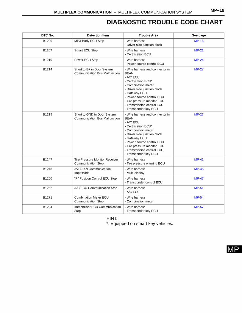
DIAGNOSTIC TROUBLE CODE CHART
HINT:*: Equipped on smart key vehicles.
DTC No. Detection Item Trouble Area See page
B1200 MPX Body ECU Stop - Wire harness- Driver side junction block
MP-18
B1207 Smart ECU Stop - Wire harness- Certification ECU
MP-21
B1210 Power ECU Stop - Wire harness- Power source control ECU
MP-24
B1214 Short to B+ in Door System Communication Bus Malfunction
- Wire harness and connector in BEAN- A/C ECU- Certification ECU*- Combination meter- Driver side junction block- Gateway ECU- Power source control ECU- Tire pressure monitor ECU- Transmission control ECU- Transponder key ECU
MP-27
B1215 Short to GND in Door System Communication Bus Malfunction
- Wire harness and connector in BEAN- A/C ECU- Certification ECU*- Combination meter- Driver side junction block- Gateway ECU- Power source control ECU- Tire pressure monitor ECU- Transmission control ECU- Transponder key ECU
MP-27
B1247 Tire Pressure Monitor Receiver Communication Stop
- Wire harness- Tire pressure warning ECU
MP-41
B1248 AVC-LAN Communication Impossible
- Wire harness- Multi-display
MP-45
B1260 "P" Position Control ECU Stop - Wire harness- Transponder control ECU
MP-47
B1262 A/C ECU Communication Stop - Wire harness- A/C ECU
MP-51
B1271 Combination Meter ECU Communication Stop
- Wire harness- Combination meter
MP-54
B1294 Immobiliser ECU Communication Stop
- Wire harness- Transponder key ECU
MP-57
MP–20 MULTIPLEX COMMUNICATION – MULTIPLEX COMMUNICATION SYSTEM
MP
DESCRIPTIONThis DTC is detected when communication between the main body ECU and gateway ECU stops for more than 10 seconds.
WIRING DIAGRAM
INSPECTION PROCEDURE
(a) Remove the DOME fuse from the engine room junction block and relay block.
(b) Measure the resistance of the fuse.
DTC B1200 MPX Body ECU Stop
DTC No. DTC Detection Condition Trouble Area
B1200 Body ECU communication stops • Driver side junction block• Wire harness
1 INSPECT FUSE (DOME)
Transponder Key ECU
MPX1
Main Body ECU
MPX2
MPX1
Driver Side Junction Block
ECUB
GND
A/C ECU
MPX2+
DOMEMAIN
B126170E02
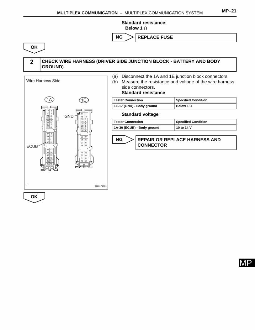
MULTIPLEX COMMUNICATION – MULTIPLEX COMMUNICATION SYSTEM MP–21
MP
Standard resistance:Below 1 Ω
NG
OK
(a) Disconnect the 1A and 1E junction block connectors.(b) Measure the resistance and voltage of the wire harness
side connectors.Standard resistance
Standard voltage
NG
OK
REPLACE FUSE
2 CHECK WIRE HARNESS (DRIVER SIDE JUNCTION BLOCK - BATTERY AND BODY GROUND)
Wire Harness Side
1A 1E
ECUB
GND
B126171E01
Tester Connection Specified Condition
1E-17 (GND) - Body ground Below 1 Ω
Tester Connection Specified Condition
1A-30 (ECUB) - Body ground 10 to 14 V
REPAIR OR REPLACE HARNESS AND CONNECTOR
MP–22 MULTIPLEX COMMUNICATION – MULTIPLEX COMMUNICATION SYSTEM
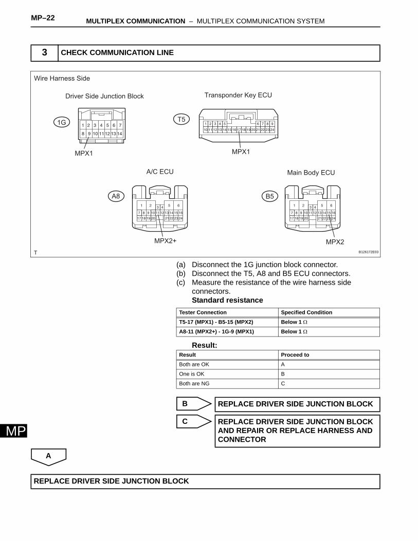
MP
(a) Disconnect the 1G junction block connector.(b) Disconnect the T5, A8 and B5 ECU connectors.(c) Measure the resistance of the wire harness side
connectors.Standard resistance
Result:
B
C
A
3 CHECK COMMUNICATION LINE
Wire Harness Side
Driver Side Junction Block
1G
MPX1
Transponder Key ECU
T5
MPX1
A/C ECU
A8
MPX2+
Main Body ECU
MPX2
B5
B126172E03
Tester Connection Specified Condition
T5-17 (MPX1) - B5-15 (MPX2) Below 1 Ω
A8-11 (MPX2+) - 1G-9 (MPX1) Below 1 Ω
Result Proceed to
Both are OK A
One is OK B
Both are NG C
REPLACE DRIVER SIDE JUNCTION BLOCK
REPLACE DRIVER SIDE JUNCTION BLOCK AND REPAIR OR REPLACE HARNESS AND CONNECTOR
REPLACE DRIVER SIDE JUNCTION BLOCK
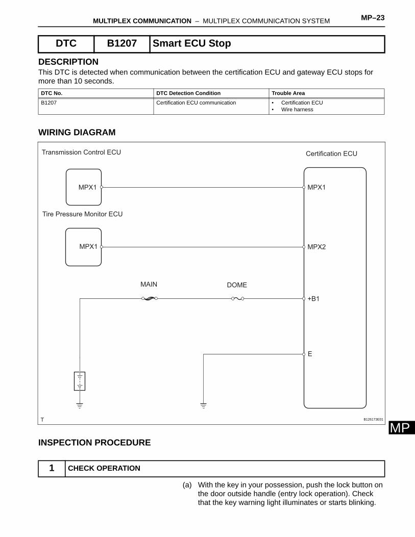
MULTIPLEX COMMUNICATION – MULTIPLEX COMMUNICATION SYSTEM MP–23
MP
DESCRIPTIONThis DTC is detected when communication between the certification ECU and gateway ECU stops for more than 10 seconds.
WIRING DIAGRAM
INSPECTION PROCEDURE
(a) With the key in your possession, push the lock button on the door outside handle (entry lock operation). Check that the key warning light illuminates or starts blinking.
DTC B1207 Smart ECU Stop
DTC No. DTC Detection Condition Trouble Area
B1207 Certification ECU communication • Certification ECU• Wire harness
1 CHECK OPERATION
Transmission Control ECU
Tire Pressure Monitor ECU
MPX1
MPX1
Certification ECU
MPX1
MPX2
+B1
E
DOMEMAIN
B126173E01
MP–24 MULTIPLEX COMMUNICATION – MULTIPLEX COMMUNICATION SYSTEM
MP
With the key in your possession, touch the inside of the door outside handle (entry unlock operation). Check that the key warning light illuminates or starts blinking.OK:
Key warning light illuminates or starts blinking.
OK
NG
(a) Disconnect the S11 ECU connector.(b) Measure the resistance and voltage of the wire harness
side connector.Standard resistance
Standard voltage
NG
OK
(a) Disconnect the S11, T4 and T11 ECU connectors.(b) Measure the resistance of the wire harness side
connectors.
Go to step 3
2 CHECK WIRE HARNESS (CERTIFICATION ECU - BODY GROUND)
262524232221201918
1 2 3 4 5 6 7 8 9 10 11 12 13 14 15 16 17
2728 29 30 31 32 33 34 35 3637 3839 40
Wire Harness Side
S11
+B1 E
B127139E01
Tester Connection Specified Condition
S11-17 (E) - Body ground Below 1 Ω
Tester Connection Specified Condition
S11-1 (+B1) - Body ground 10 to 14 V
REPAIR OR REPLACE HARNESS AND CONNECTOR
3 CHECK RESISTANCE OF COMMUNICATION LINE
Wire Harness Side
Certification ECU
S11 T4
Transmission Control ECU
T11
Tire Pressure Monitor ECU
MPX1 MPX2MPX1 MPX1
B130304E02
MULTIPLEX COMMUNICATION – MULTIPLEX COMMUNICATION SYSTEM MP–25
MP
Standard resistance
Result:
B
C
A
Tester Connection Specified Condition
S11-31 (MPX1) - T4-19 (MPX1) Below 1 Ω
S11-32 (MPX2) - T11-6 (MPX1) Below 1 Ω
Result Proceed to
Both are OK A
One is OK B
Both are NG C
REPLACE CERTIFICATION ECU AND REPAIR OR REPLACE HARNESS AND CONNECTOR
REPAIR OR REPLACE HARNESS AND CONNECTOR
REPLACE CERTIFICATION ECU
MP–26 MULTIPLEX COMMUNICATION – MULTIPLEX COMMUNICATION SYSTEM
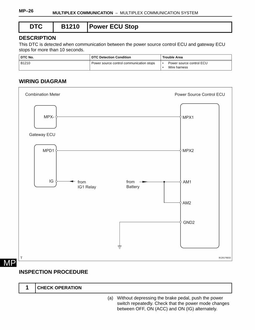
MP
DESCRIPTIONThis DTC is detected when communication between the power source control ECU and gateway ECU stops for more than 10 seconds.
WIRING DIAGRAM
INSPECTION PROCEDURE
(a) Without depressing the brake pedal, push the power switch repeatedly. Check that the power mode changes between OFF, ON (ACC) and ON (IG) alternately.
DTC B1210 Power ECU Stop
DTC No. DTC Detection Condition Trouble Area
B1210 Power source control communication stops • Power source control ECU• Wire harness
1 CHECK OPERATION
Combination Meter
Gateway ECU
MPX-
MPD1
IG from
IG1 Relay
Power Source Control ECU
MPX1
MPX2
AM1
AM2
from
Battery
GND2
B126176E02
MULTIPLEX COMMUNICATION – MULTIPLEX COMMUNICATION SYSTEM MP–27
MP
OK:Key warning light illuminates or starts blinking according to power modes.
OK
NG
(a) Disconnect the P6 ECU connector.(b) Measure the resistance and voltage of the wire harness
side connector.Standard resistance
Standard voltage
NG
OK
(a) Disconnect the P6 and G1 ECU connectors.(b) Disconnect the C10 meter connector.(c) Measure the resistance between the wire harness side
connectors.
Go to step 3
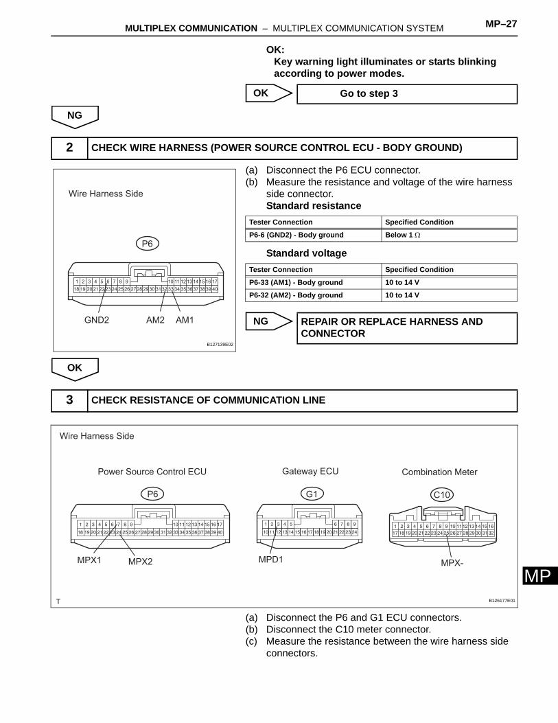
2 CHECK WIRE HARNESS (POWER SOURCE CONTROL ECU - BODY GROUND)
262524232221201918
1 2 3 4 5 6 7 8 9 10 11 12 13 14 15 16 17
2728 29 30 31 32 33 34 35 3637 3839 40
Wire Harness Side
P6
GND2 AM2 AM1
B127139E02
Tester Connection Specified Condition
P6-6 (GND2) - Body ground Below 1 Ω
Tester Connection Specified Condition
P6-33 (AM1) - Body ground 10 to 14 V
P6-32 (AM2) - Body ground 10 to 14 V
REPAIR OR REPLACE HARNESS AND CONNECTOR
3 CHECK RESISTANCE OF COMMUNICATION LINE
Wire Harness Side
P6
Power Source Control ECU
G1
Gateway ECU
C10
Combination Meter
MPX-MPD1MPX1 MPX2
B126177E01
MP–28 MULTIPLEX COMMUNICATION – MULTIPLEX COMMUNICATION SYSTEM
MP
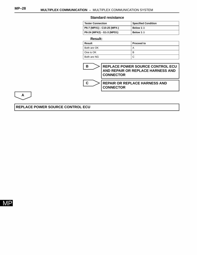
Standard resistance
Result:
B
C
A
Tester Connection Specified Condition
P6-7 (MPX1) - C10-25 (MPX-) Below 1 Ω
P6-24 (MPX2) - G1-3 (MPD1) Below 1 Ω
Result Proceed to
Both are OK A
One is OK B
Both are NG C
REPLACE POWER SOURCE CONTROL ECU AND REPAIR OR REPLACE HARNESS AND CONNECTOR
REPAIR OR REPLACE HARNESS AND CONNECTOR
REPLACE POWER SOURCE CONTROL ECU
MULTIPLEX COMMUNICATION – MULTIPLEX COMMUNICATION SYSTEM MP–29
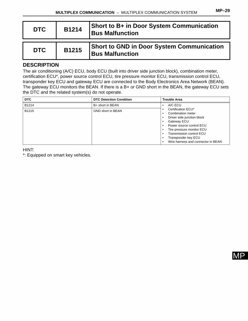
MP
DESCRIPTIONThe air conditioning (A/C) ECU, body ECU (built into driver side junction block), combination meter, certification ECU*, power source control ECU, tire pressure monitor ECU, transmission control ECU, transponder key ECU and gateway ECU are connected to the Body Electronics Area Network (BEAN). The gateway ECU monitors the BEAN. If there is a B+ or GND short in the BEAN, the gateway ECU sets the DTC and the related system(s) do not operate.
HINT:*: Equipped on smart key vehicles.
DTC B1214 Short to B+ in Door System Communication Bus Malfunction
DTC B1215 Short to GND in Door System Communication Bus Malfunction
DTC DTC Detection Condition Trouble Area
B1214 B+ short in BEAN • A/C ECU• Certification ECU*• Combination meter• Driver side junction block• Gateway ECU• Power source control ECU• Tire pressure monitor ECU• Transmission control ECU• Transponder key ECU• Wire harness and connector in BEAN
B1215 GND short in BEAN
MP–30 MULTIPLEX COMMUNICATION – MULTIPLEX COMMUNICATION SYSTEM
MP
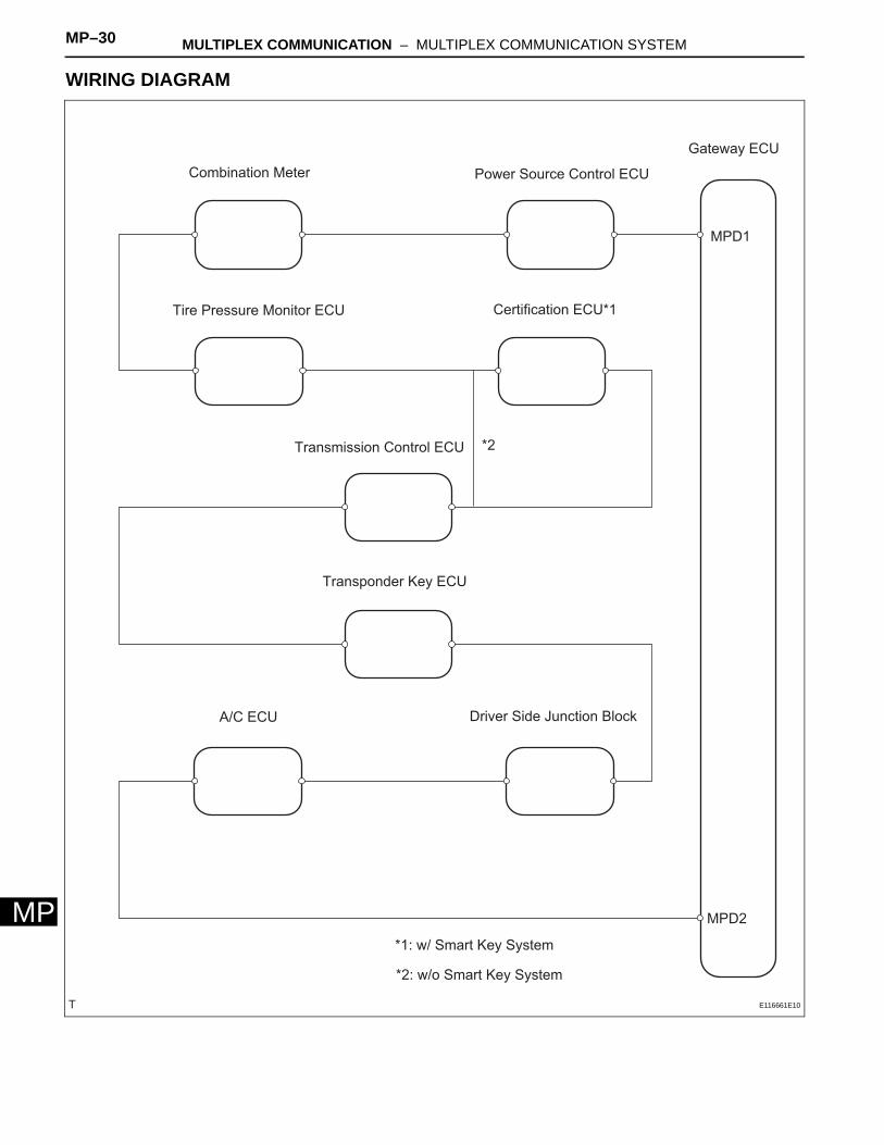
WIRING DIAGRAM
Combination Meter
Tire Pressure Monitor ECU
Power Source Control ECU
Gateway ECU
MPD1
MPD2
Certification ECU*1
Transmission Control ECU *2
Transponder Key ECU
A/C ECU Driver Side Junction Block
*1: w/ Smart Key System
*2: w/o Smart Key System
E116661E10
MULTIPLEX COMMUNICATION – MULTIPLEX COMMUNICATION SYSTEM MP–31
MP
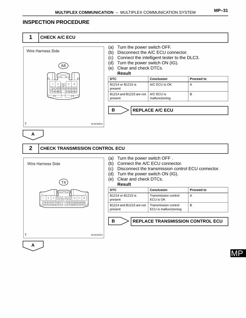
INSPECTION PROCEDURE
(a) Turn the power switch OFF.(b) Disconnect the A/C ECU connector.(c) Connect the intelligent tester to the DLC3.(d) Turn the power switch ON (IG).(e) Clear and check DTCs.
Result
B
A
(a) Turn the power switch OFF .(b) Connect the A/C ECU connector.(c) Disconnect the transmission control ECU connector.(d) Turn the power switch ON (IG).(e) Clear and check DTCs.
Result
B
A
1 CHECK A/C ECU
Wire Harness Side
A8
B126184E01
DTC Conclusion Proceed to
B1214 or B1215 is present
A/C ECU is OK A
B1214 and B1215 are not present
A/C ECU is malfunctioning
B
REPLACE A/C ECU
2 CHECK TRANSMISSION CONTROL ECU
Wire Harness Side
T4
B126181E01
DTC Conclusion Proceed to
B1214 or B1215 is present
Transmission control ECU is OK
A
B1214 and B1215 are not present
Transmission control ECU is malfunctioning
B
REPLACE TRANSMISSION CONTROL ECU
MP–32 MULTIPLEX COMMUNICATION – MULTIPLEX COMMUNICATION SYSTEM
MP
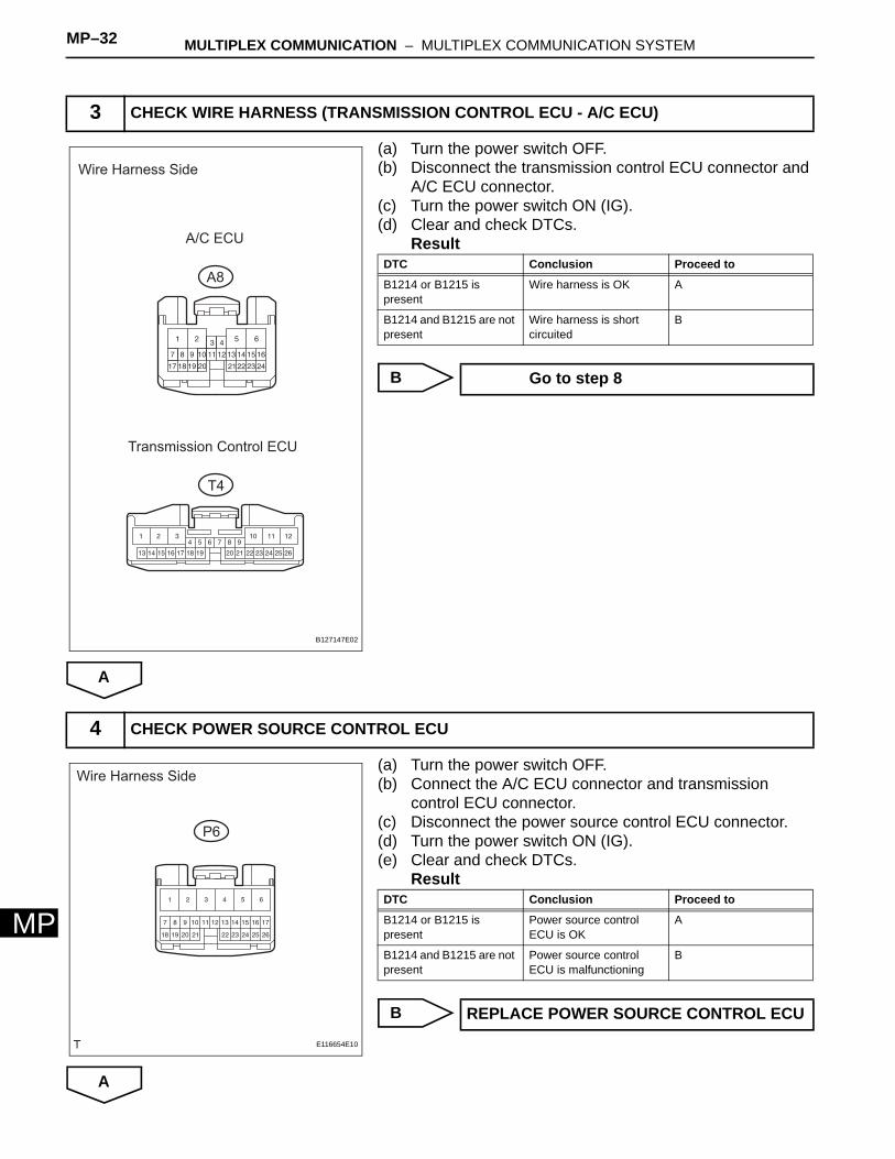
(a) Turn the power switch OFF.(b) Disconnect the transmission control ECU connector and
A/C ECU connector.(c) Turn the power switch ON (IG).(d) Clear and check DTCs.
Result
B
A
(a) Turn the power switch OFF.(b) Connect the A/C ECU connector and transmission
control ECU connector.(c) Disconnect the power source control ECU connector.(d) Turn the power switch ON (IG).(e) Clear and check DTCs.
Result
B
A
3 CHECK WIRE HARNESS (TRANSMISSION CONTROL ECU - A/C ECU)
Wire Harness Side
A/C ECU
A8
Transmission Control ECU
T4
B127147E02
DTC Conclusion Proceed to
B1214 or B1215 is present
Wire harness is OK A
B1214 and B1215 are not present
Wire harness is short circuited
B
Go to step 8
4 CHECK POWER SOURCE CONTROL ECU
Wire Harness Side
P6
E116654E10
DTC Conclusion Proceed to
B1214 or B1215 is present
Power source control ECU is OK
A
B1214 and B1215 are not present
Power source control ECU is malfunctioning
B
REPLACE POWER SOURCE CONTROL ECU
MULTIPLEX COMMUNICATION – MULTIPLEX COMMUNICATION SYSTEM MP–33
MP
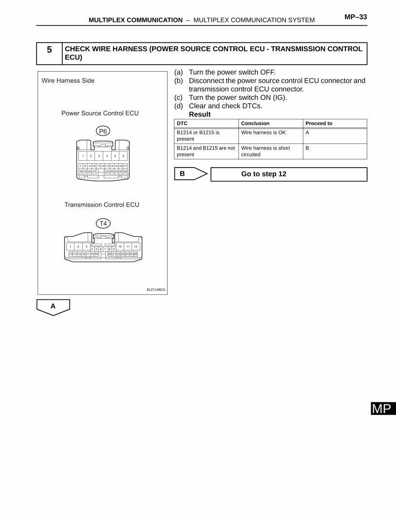
(a) Turn the power switch OFF.(b) Disconnect the power source control ECU connector and
transmission control ECU connector.(c) Turn the power switch ON (IG).(d) Clear and check DTCs.
Result
B
A
5 CHECK WIRE HARNESS (POWER SOURCE CONTROL ECU - TRANSMISSION CONTROL ECU)
Wire Harness Side
Power Source Control ECU
P6
Transmission Control ECU
T4
B127148E01
DTC Conclusion Proceed to
B1214 or B1215 is present
Wire harness is OK A
B1214 and B1215 are not present
Wire harness is short circuited
B
Go to step 12
MP–34 MULTIPLEX COMMUNICATION – MULTIPLEX COMMUNICATION SYSTEM
MP
(a) Turn the power switch OFF.(b) Connect the transmission control ECU connector.(c) Disconnect the power source control ECU connector and
gateway ECU connector.(d) Measure the resistance and voltage of the gateway ECU
connector terminal.Standard resistance
Standard voltage
NG
OK
6 CHECK WIRE HARNESS (GATEWAY ECU - POWER SOURCE CONTROL ECU)
Wire Harness Side
Gateway ECU
G1
MPD1
Power Source Control ECU
P6
MPX2
B127150E02
Tester Connection Specified Condition
G1-3 (MPD1) - Body ground 10 kΩ or higher
Tester Connection Condition Specified Condition
G1-3 (MPD1) - Body ground
Power switch ON (IG) Below 1 V
REPAIR OR REPLACE HARNESS AND CONNECTOR

MULTIPLEX COMMUNICATION – MULTIPLEX COMMUNICATION SYSTEM MP–35
MP
(a) Turn the power switch OFF.(b) Connect the power source control ECU connector.(c) Disconnect the A/C ECU connector and gateway ECU
connector.(d) Measure the resistance and voltage of the gateway ECU
connector terminal.Standard resistance
Standard voltage
NG
OK
7 CHECK WIRE HARNESS (GATEWAY ECU - A/C ECU)
Wire Harness Side
Gateway ECU
G1
A8
A/C ECU
MPD2
MPX+
B127149E02
Tester Connection Specified Condition
G1-12 (MPD2) - Body ground 10 kΩ or higher
Tester Connection Condition Specified Condition
G1-12 (MPD2) - Body ground
Power switch ON (IG) Below 1 V
REPAIR OR REPLACE HARNESS AND CONNECTOR
REPLACE GATEWAY ECU
MP–36 MULTIPLEX COMMUNICATION – MULTIPLEX COMMUNICATION SYSTEM
MP
(a) Turn the power switch OFF.(b) Connect the A/C ECU connector and transmission
control ECU connector.(c) Disconnect the 1G driver side junction block connector
and B5 main body ECU connector.(d) Turn the power switch ON (IG).(e) Clear and check DTCs.
Result
B
A
8 CHECK DRIVER SIDE JUNCTION BLOCK
Wire Harness Side
Driver Side Junction Block
1G
Main Body ECU
B5
B127151E02
DTC Conclusion Proceed to
B1214 or B1215 is present
Driver side junction block is OK
A
B1214 and B1215 are not present
Driver side junction block is malfunctioning
B
REPLACE DRIVER SIDE JUNCTION BLOCK
MULTIPLEX COMMUNICATION – MULTIPLEX COMMUNICATION SYSTEM MP–37
MP
(a) Turn the power switch OFF.(b) Connect the B5 ECU connector.(c) Disconnect the 1G driver side junction block connector
and A/C ECU connector.(d) Turn the power switch ON (IG).(e) Clear and check DTCs.
Result
B
A
(a) Turn the power switch OFF.(b) Connect the driver side junction block connector and A/C
ECU connector.(c) Disconnect the transponder key ECU connector.(d) Turn the power switch ON (IG).(e) Clear and check DTCs.
Result
B
A
9 CHECK WIRE HARNESS (DRIVER SIDE JUNCTION BLOCK - A/C ECU)
Wire Harness Side
A/C ECU
A8
1G
Driver Side Junction Block
B127152E03
DTC Conclusion Proceed to
B1214 or B1215 is present
Wire harness is OK A
B1214 and B1215 are not present
Wire harness is short circuited
B
REPAIR OR REPLACE HARNESS AND CONNECTOR
10 CHECK TRANSPONDER KEY ECU
Wire Harness Side
T5
B127153E01
DTC Conclusion Proceed to
B1214 or B1215 is present
Transponder key ECU is OK
A
B1214 and B1215 are not present
Transponder key ECU is malfunctioning
B
REPLACE TRANSPONDER KEY ECU
MP–38 MULTIPLEX COMMUNICATION – MULTIPLEX COMMUNICATION SYSTEM
MP
(a) Turn the power switch OFF.(b) Disconnect the transponder key ECU connector and B5
ECU connector.(c) Turn the power switch ON (IG).(d) Clear and check DTCs.
Result
B
A
11 CHECK WIRE HARNESS (TRANSPONDER KEY ECU - DRIVER SIDE JUNCTION BLOCK)
Wire Harness Side
Main Body ECU
B5
Transponder Key ECU
T5
B127154E02
DTC Conclusion Proceed to
B1214 or B1215 is present
Wire harness is OK A
B1214 and B1215 are not present
Wire harness is short circuited
B
REPAIR OR REPLACE HARNESS AND CONNECTOR (TRANSPONDER KEY ECU - DRIVER SIDE JUNCTION BLOCK)
REPAIR OR REPLACE HARNESS AND CONNECTOR (TRANSPONDER KEY ECU - TRANSMISSION CONTROL ECU)
MULTIPLEX COMMUNICATION – MULTIPLEX COMMUNICATION SYSTEM MP–39
MP
(a) Turn the power switch OFF.(b) Connect the power source control ECU connector and
transmission control ECU connector.(c) Disconnect the C10 meter connector.(d) Turn the ignition switch ON (IG).(e) Clear and check DTCs.
Result
B
A
(a) Turn the power switch OFF.(b) Disconnect the C10 combination meter and power
source control ECU connector.(c) Turn the power switch ON (IG).(d) Clear and check DTCs.
Result
B
A
12 CHECK COMBINATION METER
Wire Harness Side
C10
B126419E02
DTC Conclusion Proceed to
B1214 or B1215 is present
Combination meter is OK A
B1214 and B1215 are not present
Combination meter is malfunctioning
B
REPLACE COMBINATION METER
13 CHECK WIRE HARNESS (COMBINATION METER - POWER SOURCE CONTROL ECU)
Wire Harness Side
Combination Meter
C10
Power Source Control ECU
P6
B130297E02
DTC Conclusion Proceed to
B1214 or B1215 is present
Wire harness is OK A
B1214 and B1215 are not present
Wire harness is short circuited
B
REPAIR OR REPLACE HARNESS AND CONNECTOR
MP–40 MULTIPLEX COMMUNICATION – MULTIPLEX COMMUNICATION SYSTEM
MP
(a) Turn the power switch OFF.(b) Connect the C10 meter connector and power source
control ECU connector.(c) Disconnect the tire pressure monitor ECU connector.(d) Turn the power switch ON (IG).(e) Clear and check DTCs.
Result
B
A
(a) Turn the power switch OFF.(b) Disconnect the tire pressure monitor ECU connector and
C10 meter connector.(c) Turn the power switch ON (IG).(d) Clear and check DTCs.
Result
B
A
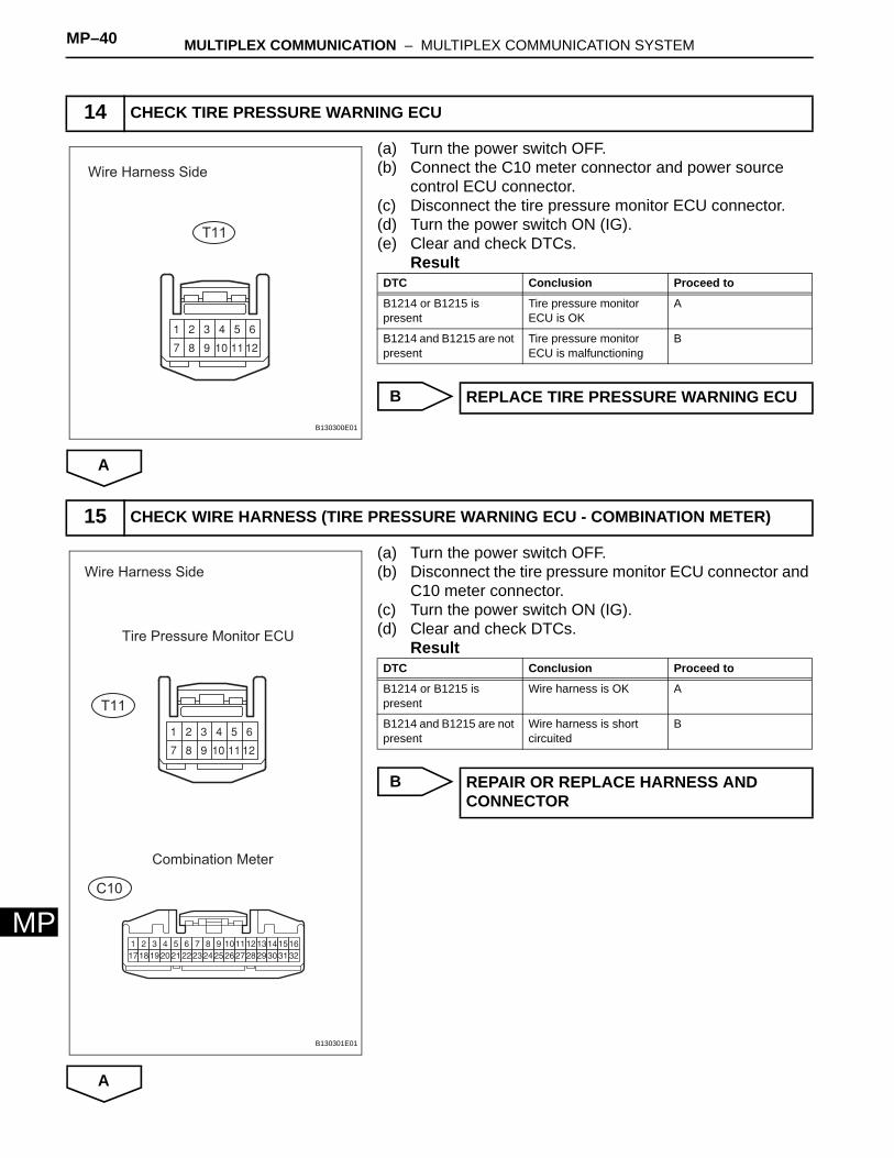
14 CHECK TIRE PRESSURE WARNING ECU
Wire Harness Side
T11
B130300E01
DTC Conclusion Proceed to
B1214 or B1215 is present
Tire pressure monitor ECU is OK
A
B1214 and B1215 are not present
Tire pressure monitor ECU is malfunctioning
B
REPLACE TIRE PRESSURE WARNING ECU
15 CHECK WIRE HARNESS (TIRE PRESSURE WARNING ECU - COMBINATION METER)
Wire Harness Side
Tire Pressure Monitor ECU
Combination Meter
T11
C10
B130301E01
DTC Conclusion Proceed to
B1214 or B1215 is present
Wire harness is OK A
B1214 and B1215 are not present
Wire harness is short circuited
B
REPAIR OR REPLACE HARNESS AND CONNECTOR
MULTIPLEX COMMUNICATION – MULTIPLEX COMMUNICATION SYSTEM MP–41
MP
Equipment
B
A
(a) Turn the power switch OFF.(b) Connect the C10 meter connector and tire pressure
monitor ECU connector.(c) Disconnect the certification ECU connector.(d) Turn the power switch ON (IG).(e) Clear and check DTCs.
Result
B
A
16 CONFIRM EQUIPMENT
Equipment Proceed to
With smart key system A
Without smart key system B
REPAIR OR REPLACE HARNESS AND CONNECTOR (TIRE PRESSURE MONITOR ECU - TRANSMISSION CONTROL ECU)
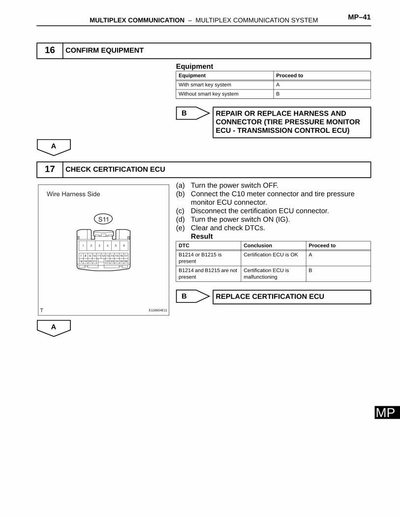
17 CHECK CERTIFICATION ECU
Wire Harness Side
S11
E116654E11
DTC Conclusion Proceed to
B1214 or B1215 is present
Certification ECU is OK A
B1214 and B1215 are not present
Certification ECU is malfunctioning
B
REPLACE CERTIFICATION ECU
MP–42 MULTIPLEX COMMUNICATION – MULTIPLEX COMMUNICATION SYSTEM
MP
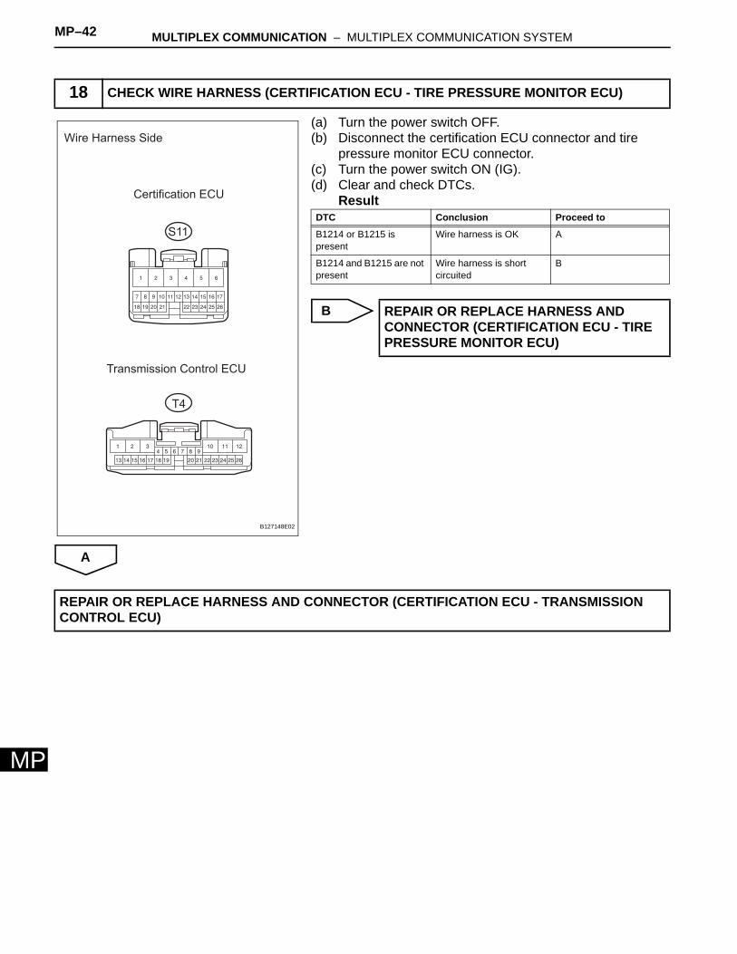
(a) Turn the power switch OFF.(b) Disconnect the certification ECU connector and tire
pressure monitor ECU connector.(c) Turn the power switch ON (IG).(d) Clear and check DTCs.
Result
B
A
18 CHECK WIRE HARNESS (CERTIFICATION ECU - TIRE PRESSURE MONITOR ECU)
Wire Harness Side
Certification ECU
S11
Transmission Control ECU
T4
B127148E02
DTC Conclusion Proceed to
B1214 or B1215 is present
Wire harness is OK A
B1214 and B1215 are not present
Wire harness is short circuited
B
REPAIR OR REPLACE HARNESS AND CONNECTOR (CERTIFICATION ECU - TIRE PRESSURE MONITOR ECU)
REPAIR OR REPLACE HARNESS AND CONNECTOR (CERTIFICATION ECU - TRANSMISSION CONTROL ECU)
MULTIPLEX COMMUNICATION – MULTIPLEX COMMUNICATION SYSTEM MP–43
MP
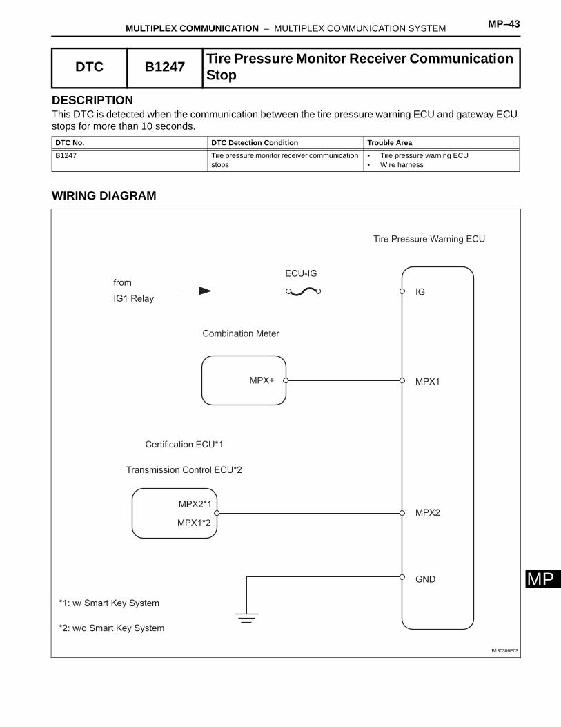
DESCRIPTIONThis DTC is detected when the communication between the tire pressure warning ECU and gateway ECU stops for more than 10 seconds.
WIRING DIAGRAM
DTC B1247 Tire Pressure Monitor Receiver Communication Stop
DTC No. DTC Detection Condition Trouble Area
B1247 Tire pressure monitor receiver communication stops
• Tire pressure warning ECU• Wire harness
Tire Pressure Warning ECU
ECU-IG
from
IG1 Relay
Combination Meter
Certification ECU*1
Transmission Control ECU*2
IG
MPX1
MPX2
GND
MPX+
MPX2*1
MPX1*2
*1: w/ Smart Key System
*2: w/o Smart Key System
B130306E03

MP–44 MULTIPLEX COMMUNICATION – MULTIPLEX COMMUNICATION SYSTEM
MP
INSPECTION PROCEDURE
(a) Remove the ECU-IG fuse from the driver side junction block.
(b) Measure the resistance of the fuse.Standard resistance:
Below 1 Ω
NG
OK
(a) Disconnect the T11 ECU connector.(b) Turn the power switch ON (IG).(c) Measure the voltage and resistance of the wire harness
side connector.Standard voltage
Standard resistance
NG
OK
1 INSPECT FUSE (ECU-IG)
REPLACE FUSE
2 CHECK WIRE HARNESS (TIRE PRESSURE WARNING ECU - BATTERY AND BODY GROUND)
1 2 3 4 5 6
7 8 9 10 11 12
Wire Harness Side
T11
IG
B108903E09
Tester Connection Condition Specified Condition
T11-1 (IG) - Body ground
Power switch ON (IG) 10 to 14 V
Tester Connection Specified Condition
T11-7 (GND) - Body ground Below 1 Ω
REPAIR OR REPLACE HARNESS AND CONNECTOR

MULTIPLEX COMMUNICATION – MULTIPLEX COMMUNICATION SYSTEM MP–45
MP
(a) Disconnect the T11, S11*1 and T4*2 ECU connectors.(b) Disconnect the C10 meter connector.(c) Measure the resistance of the wire harness side
connector.Standard resistance
3 CHECK RESISTANCE OF COMMUNICATION LINE
Certification ECU*1
S11
Transmission Control ECU*2 Tire Pressure Warning ECU
T11T4
Wire Harness Side
MPX1MPX1MPX2
*1: w/ Smart Key *2: w/o Smart Key
B130304E05
Certification ECU*1
S11
Transmission Control ECU*2
Tire Pressure Warning ECU
T11
T4
Wire Harness Side
MPX1
MPX1MPX2
*1: w/ Smart Key System (for Door Lock) *2: w/o Smart Key System (for Door Lock)
Combination Meter
C10
MPX+
MPX2
B131912E02
Tester Connection Specified Condition
T11-6 (MPX1) - S11-32 (MPX2)*1 Below 1 Ω
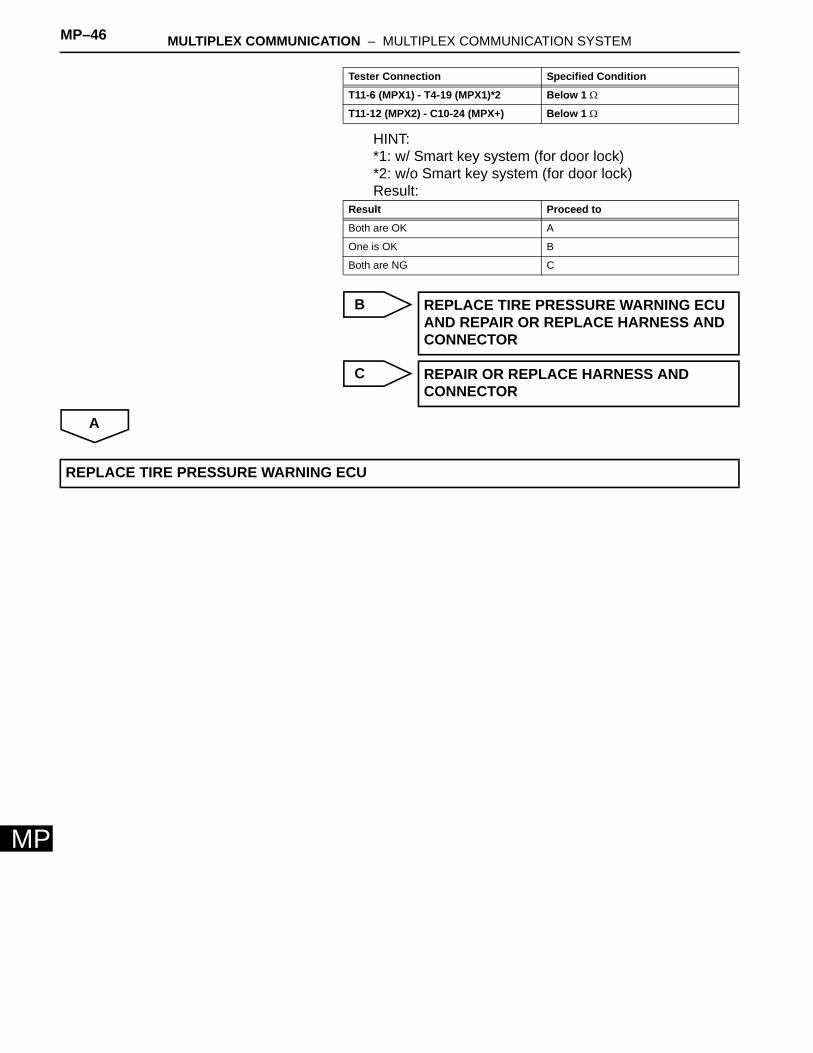
MP–46 MULTIPLEX COMMUNICATION – MULTIPLEX COMMUNICATION SYSTEM
MP
HINT:*1: w/ Smart key system (for door lock) *2: w/o Smart key system (for door lock)Result:
B
C
A
T11-6 (MPX1) - T4-19 (MPX1)*2 Below 1 Ω
T11-12 (MPX2) - C10-24 (MPX+) Below 1 Ω
Result Proceed to
Both are OK A
One is OK B
Both are NG C
REPLACE TIRE PRESSURE WARNING ECU AND REPAIR OR REPLACE HARNESS AND CONNECTOR
REPAIR OR REPLACE HARNESS AND CONNECTOR
Tester Connection Specified Condition
REPLACE TIRE PRESSURE WARNING ECU
MULTIPLEX COMMUNICATION – MULTIPLEX COMMUNICATION SYSTEM MP–47
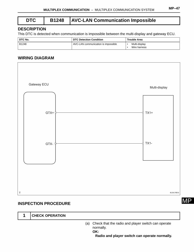
MP
DESCRIPTIONThis DTC is detected when communication is impossible between the multi-display and gateway ECU.
WIRING DIAGRAM
INSPECTION PROCEDURE
(a) Check that the radio and player switch can operate normally.OK:
Radio and player switch can operate normally.
DTC B1248 AVC-LAN Communication Impossible
DTC No. DTC Detection Condition Trouble Area
B1248 AVC-LAN communication is impossible • Multi-display• Wire harness
1 CHECK OPERATION
Gateway ECU
GTX+
GTX-
Multi-display
TX1+
TX1-
B126178E01
MP–48 MULTIPLEX COMMUNICATION – MULTIPLEX COMMUNICATION SYSTEM
MP
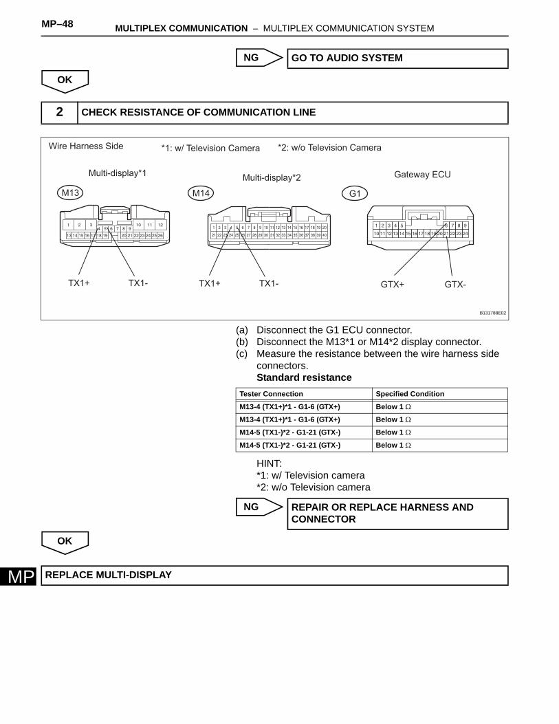
NG
OK
(a) Disconnect the G1 ECU connector.(b) Disconnect the M13*1 or M14*2 display connector.(c) Measure the resistance between the wire harness side
connectors.Standard resistance
HINT:*1: w/ Television camera *2: w/o Television camera
NG
OK
GO TO AUDIO SYSTEM
2 CHECK RESISTANCE OF COMMUNICATION LINE
Wire Harness Side
Multi-display*1 Gateway ECU
M13 G1
TX1+ TX1- GTX-GTX+
Multi-display*2
M14
TX1+ TX1-
*1: w/ Television Camera *2: w/o Television Camera
B131788E02
Tester Connection Specified Condition
M13-4 (TX1+)*1 - G1-6 (GTX+) Below 1 Ω
M13-4 (TX1+)*1 - G1-6 (GTX+) Below 1 Ω
M14-5 (TX1-)*2 - G1-21 (GTX-) Below 1 Ω
M14-5 (TX1-)*2 - G1-21 (GTX-) Below 1 Ω
REPAIR OR REPLACE HARNESS AND CONNECTOR
REPLACE MULTI-DISPLAY
MULTIPLEX COMMUNICATION – MULTIPLEX COMMUNICATION SYSTEM MP–49
MP
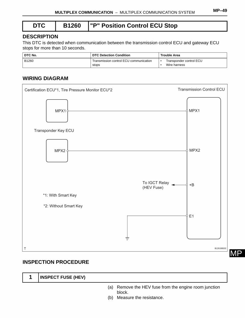
DESCRIPTIONThis DTC is detected when communication between the transmission control ECU and gateway ECU stops for more than 10 seconds.
WIRING DIAGRAM
INSPECTION PROCEDURE
(a) Remove the HEV fuse from the engine room junction block.
(b) Measure the resistance.
DTC B1260 "P" Position Control ECU Stop
DTC No. DTC Detection Condition Trouble Area
B1260 Transmission control ECU communication stops
• Transponder control ECU• Wire harness
1 INSPECT FUSE (HEV)
Transponder Key ECU
MPX1 MPX1
MPX2 MPX2
+B
Transmission Control ECU
E1
To IGCT Relay
(HEV Fuse)
Certification ECU*1, Tire Pressure Monitor ECU*2
*1: With Smart Key
*2: Without Smart Key
B126180E02
MP–50 MULTIPLEX COMMUNICATION – MULTIPLEX COMMUNICATION SYSTEM
MP
Standard resistance:Below 1 Ω
NG
OK
(a) Disconnect the T4 ECU connector.(b) Measure the resistance and voltage between the wire
harness side connector.Standard resistance
Standard voltage
NG
OK
REPLACE FUSE
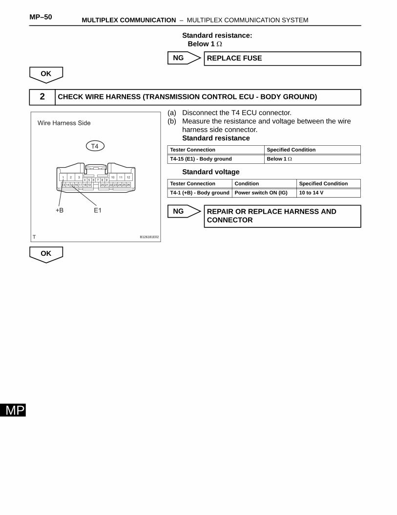
2 CHECK WIRE HARNESS (TRANSMISSION CONTROL ECU - BODY GROUND)
Wire Harness Side
T4
E1+B
B126181E02
Tester Connection Specified Condition
T4-15 (E1) - Body ground Below 1 Ω
Tester Connection Condition Specified Condition
T4-1 (+B) - Body ground Power switch ON (IG) 10 to 14 V
REPAIR OR REPLACE HARNESS AND CONNECTOR
MULTIPLEX COMMUNICATION – MULTIPLEX COMMUNICATION SYSTEM MP–51
MP
(a) Disconnect the T4, T5 and S11*1 or T11*2 ECU connectors.
(b) Measure the resistance of the wire harness side connectors.Standard resistance
HINT:*1: w/ Smart key system (for door lock) *2: w/o Smart key system (for door lock)Result:
B
3 CHECK RESISTANCE OF COMMUNICATION LINE
Wire Harness Side
Transmission Control ECU
T4
Transponder Key ECU
Certification ECU*1
T5
S11
MPX2 MPX2MPX1
MPX1MPX1
T11
Tire Pressure Monitor ECU*2
*1: w/ Smart Key System (for Door Lock) *2: w/o Smart Key System (for Door Lock)
B131880E01
Tester Connection Specified Condition
T4-18 (MPX2) - T5-16 (MPX2) Below 1 Ω
T4-19 (MPX1) - S11-31 (MPX1)*1 Below 1 Ω
T4-19 (MPX1) - T11-6 (MPX1)*2 Below 1 Ω
Result Proceed to
Both are OK A
One is OK B
Both are NG C
REPLACE TRANSMISSION CONTROL ECU AND REPAIR OR REPLACE HARNESS AND CONNECTOR
MP–52 MULTIPLEX COMMUNICATION – MULTIPLEX COMMUNICATION SYSTEM
MP
C
A
REPAIR OR REPLACE HARNESS AND CONNECTOR
REPLACE TRANSMISSION CONTROL ECU
MULTIPLEX COMMUNICATION – MULTIPLEX COMMUNICATION SYSTEM MP–53
MP
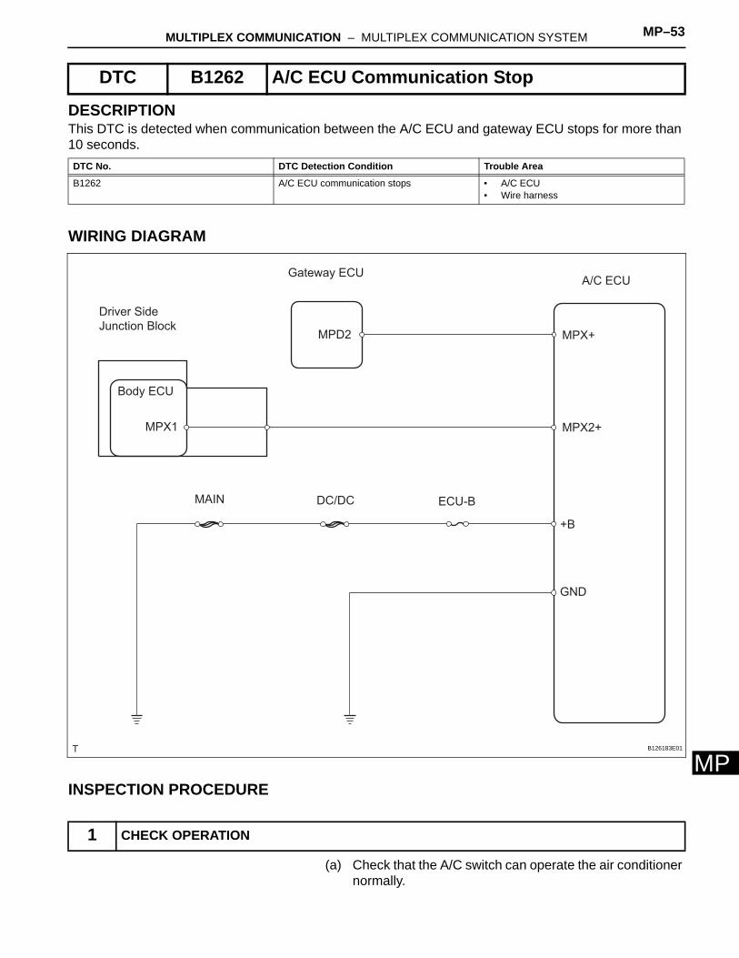
DESCRIPTIONThis DTC is detected when communication between the A/C ECU and gateway ECU stops for more than 10 seconds.
WIRING DIAGRAM
INSPECTION PROCEDURE
(a) Check that the A/C switch can operate the air conditioner normally.
DTC B1262 A/C ECU Communication Stop
DTC No. DTC Detection Condition Trouble Area
B1262 A/C ECU communication stops • A/C ECU• Wire harness
1 CHECK OPERATION
Driver Side
Junction Block
Gateway ECU
Body ECU
MPD2
MPX1
A/C ECU
MPX+
MPX2+
+B
GND
ECU-BDC/DCMAIN
B126183E01
MP–54 MULTIPLEX COMMUNICATION – MULTIPLEX COMMUNICATION SYSTEM
MP
OK:A/C switch can operate the air conditioner normally.
OK
NG
(a) Disconnect the A8 ECU connector.(b) Measure the resistance and voltage of the wire harness
side connector.Standard resistance
Standard voltage
NG
OK
(a) Disconnect the A8 and G1 ECU connectors.(b) Disconnect the 1G junction block connector.(c) Measure the resistance of the wire harness side
connectors.
Go to step 3
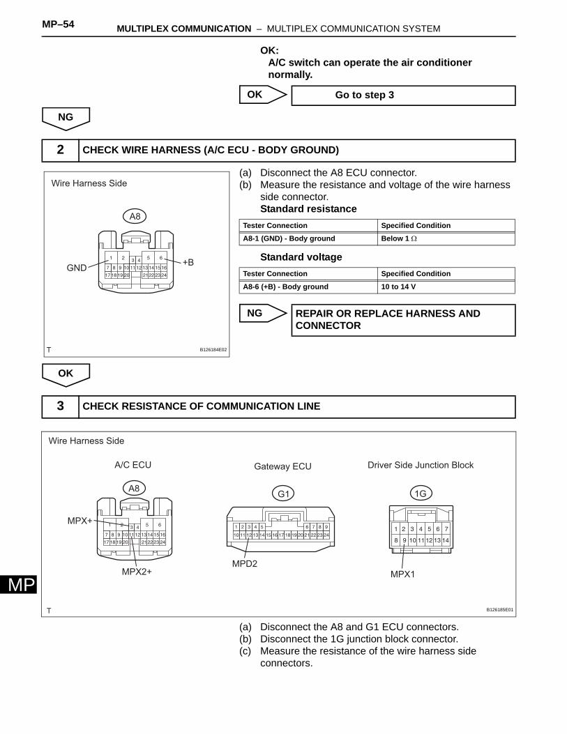
2 CHECK WIRE HARNESS (A/C ECU - BODY GROUND)
Wire Harness Side
A8
GND+B
B126184E02
Tester Connection Specified Condition
A8-1 (GND) - Body ground Below 1 Ω
Tester Connection Specified Condition
A8-6 (+B) - Body ground 10 to 14 V
REPAIR OR REPLACE HARNESS AND CONNECTOR
3 CHECK RESISTANCE OF COMMUNICATION LINE
Wire Harness Side
A/C ECU Gateway ECU
A8G1
Driver Side Junction Block
1G
MPX+
MPX2+MPD2
MPX1
B126185E01
MULTIPLEX COMMUNICATION – MULTIPLEX COMMUNICATION SYSTEM MP–55
MP
Standard resistance
Result:
B
C
A
Tester Connection Specified Condition
A8-3 (MPX+) - G1-12 (MPD2) Below 1 Ω
A8-11 (MPX2+) - 1G-9 (MPX1) Below 1 Ω
Result Proceed to
Both are OK A
One is OK B
Both are NG C
REPLACE A/C ECU AND REPAIR OR REPLACE HARNESS AND CONNECTOR
REPAIR OR REPLACE HARNESS AND CONNECTOR
REPLACE A/C ECU
MP–56 MULTIPLEX COMMUNICATION – MULTIPLEX COMMUNICATION SYSTEM
MP
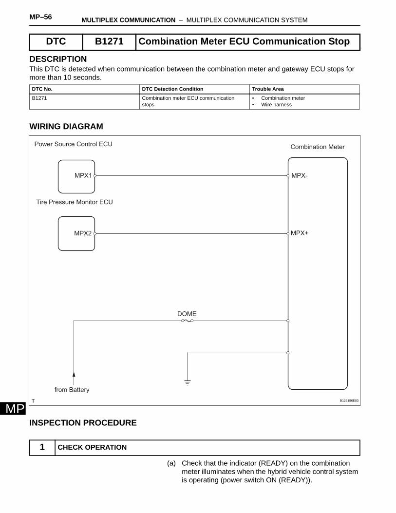
DESCRIPTIONThis DTC is detected when communication between the combination meter and gateway ECU stops for more than 10 seconds.
WIRING DIAGRAM
INSPECTION PROCEDURE
(a) Check that the indicator (READY) on the combination meter illuminates when the hybrid vehicle control system is operating (power switch ON (READY)).
DTC B1271 Combination Meter ECU Communication Stop
DTC No. DTC Detection Condition Trouble Area
B1271 Combination meter ECU communication stops
• Combination meter• Wire harness
1 CHECK OPERATION
Power Source Control ECU
Tire Pressure Monitor ECU
MPX1
MPX2
Combination Meter
MPX-
MPX+
DOME
from Battery
B126186E03
MULTIPLEX COMMUNICATION – MULTIPLEX COMMUNICATION SYSTEM MP–57
MP
OK:Indicator can operate properly.
OK
NG
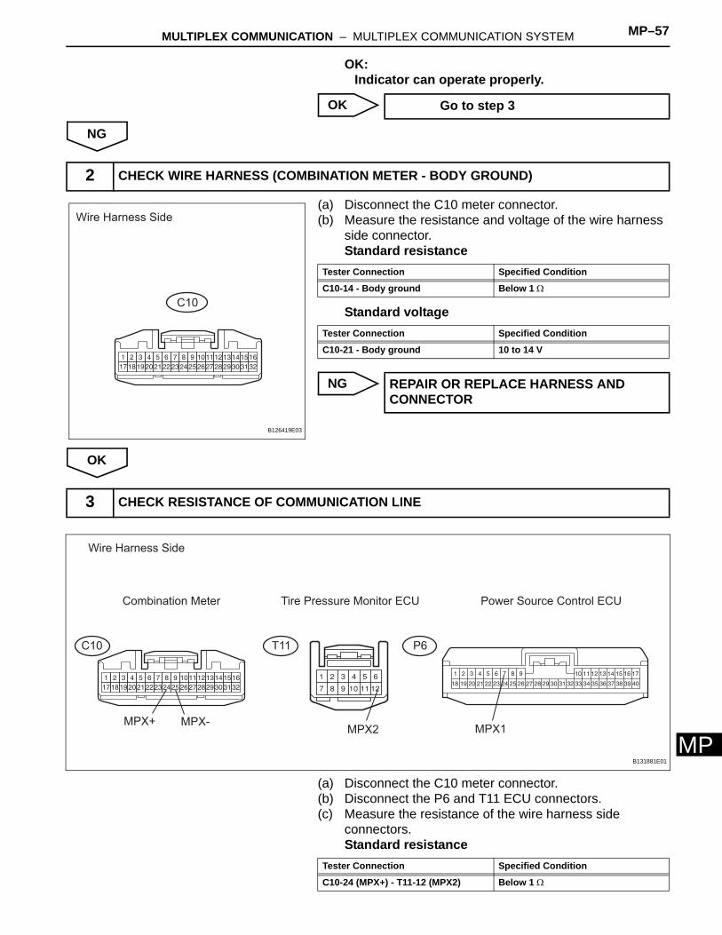
(a) Disconnect the C10 meter connector.(b) Measure the resistance and voltage of the wire harness
side connector.Standard resistance
Standard voltage
NG
OK
(a) Disconnect the C10 meter connector.(b) Disconnect the P6 and T11 ECU connectors.(c) Measure the resistance of the wire harness side
connectors.Standard resistance
Go to step 3
2 CHECK WIRE HARNESS (COMBINATION METER - BODY GROUND)
Wire Harness Side
C10
B126419E03
Tester Connection Specified Condition
C10-14 - Body ground Below 1 Ω
Tester Connection Specified Condition
C10-21 - Body ground 10 to 14 V
REPAIR OR REPLACE HARNESS AND CONNECTOR
3 CHECK RESISTANCE OF COMMUNICATION LINE
C10
Wire Harness Side
Combination Meter
T11
Tire Pressure Monitor ECU Power Source Control ECU
P6
MPX+ MPX-MPX2 MPX1
B131881E01
Tester Connection Specified Condition
C10-24 (MPX+) - T11-12 (MPX2) Below 1 Ω
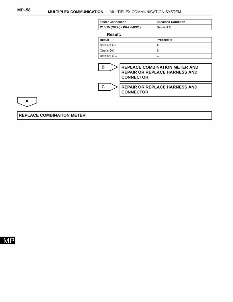
MP–58 MULTIPLEX COMMUNICATION – MULTIPLEX COMMUNICATION SYSTEM
MP
Result:
B
C
A
C10-25 (MPX-) - P6-7 (MPX1) Below 1 Ω
Result Proceed to
Both are OK A
One is OK B
Both are NG C
REPLACE COMBINATION METER AND REPAIR OR REPLACE HARNESS AND CONNECTOR
REPAIR OR REPLACE HARNESS AND CONNECTOR
Tester Connection Specified Condition
REPLACE COMBINATION METER
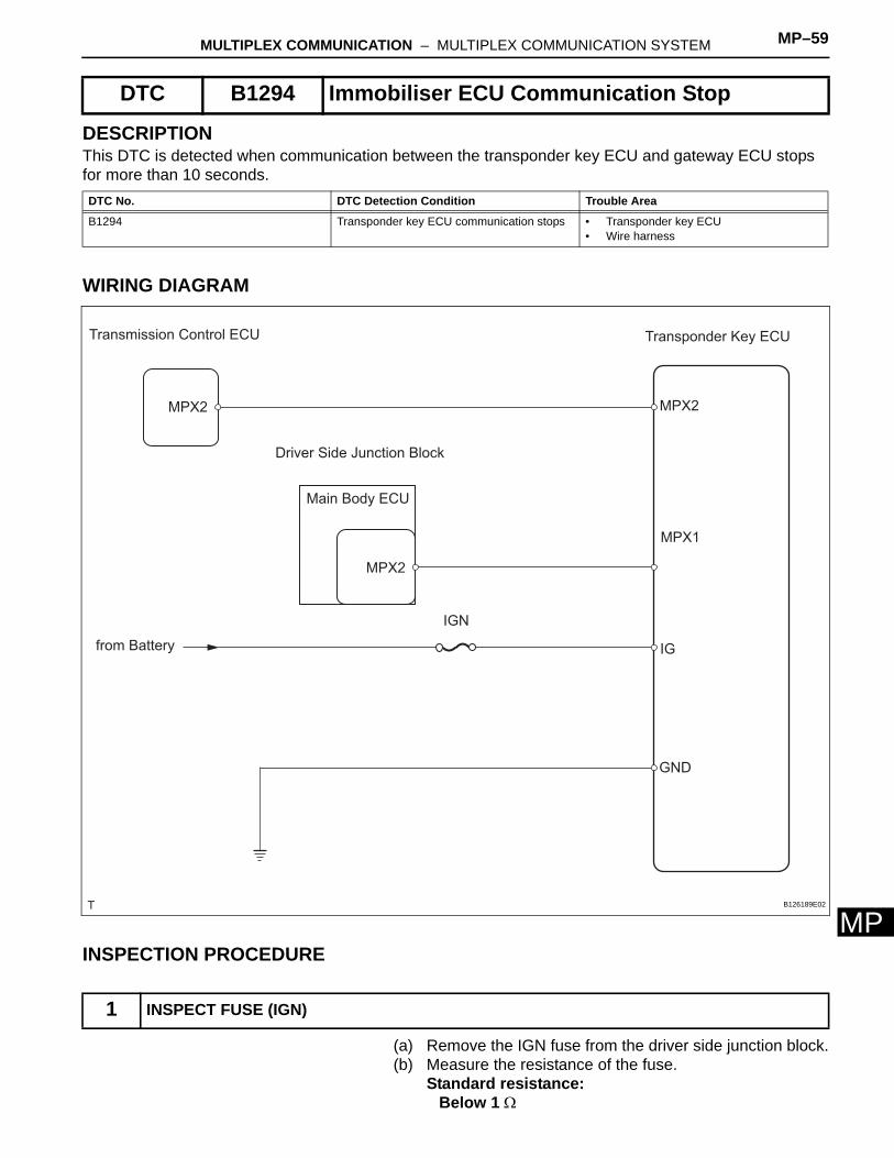
MULTIPLEX COMMUNICATION – MULTIPLEX COMMUNICATION SYSTEM MP–59
MP
DESCRIPTIONThis DTC is detected when communication between the transponder key ECU and gateway ECU stops for more than 10 seconds.
WIRING DIAGRAM
INSPECTION PROCEDURE
(a) Remove the IGN fuse from the driver side junction block.(b) Measure the resistance of the fuse.
Standard resistance:Below 1 Ω
DTC B1294 Immobiliser ECU Communication Stop
DTC No. DTC Detection Condition Trouble Area
B1294 Transponder key ECU communication stops • Transponder key ECU• Wire harness
1 INSPECT FUSE (IGN)
Transmission Control ECU
Main Body ECU
MPX2
MPX2
from Battery
Transponder Key ECU
MPX2
MPX1
IG
GND
IGN
Driver Side Junction Block
B126189E02
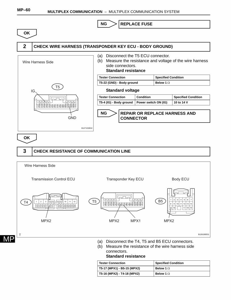
MP–60 MULTIPLEX COMMUNICATION – MULTIPLEX COMMUNICATION SYSTEM
MP
NG
OK
(a) Disconnect the T5 ECU connector.(b) Measure the resistance and voltage of the wire harness
side connectors.Standard resistance
Standard voltage
NG
OK
(a) Disconnect the T4, T5 and B5 ECU connectors.(b) Measure the resistance of the wire harness side
connectors.Standard resistance
REPLACE FUSE
2 CHECK WIRE HARNESS (TRANSPONDER KEY ECU - BODY GROUND)
Wire Harness Side
T5
IG
GND
B127153E02
Tester Connection Specified Condition
T5-22 (GND) - Body ground Below 1 Ω
Tester Connection Condition Specified Condition
T5-4 (IG) - Body ground Power switch ON (IG) 10 to 14 V
REPAIR OR REPLACE HARNESS AND CONNECTOR
3 CHECK RESISTANCE OF COMMUNICATION LINE
Wire Harness Side
T4
Transmission Control ECU
T5
Transponder Key ECU
B5
Body ECU
MPX2 MPX2 MPX2MPX1
B126190E01
Tester Connection Specified Condition
T5-17 (MPX1) - B5-15 (MPX2) Below 1 Ω
T5-16 (MPX2) - T4-18 (MPX2) Below 1 Ω
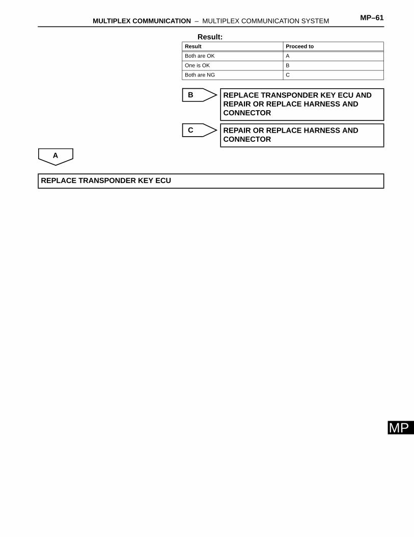
MULTIPLEX COMMUNICATION – MULTIPLEX COMMUNICATION SYSTEM MP–61
MP
Result:
B
C
A
Result Proceed to
Both are OK A
One is OK B
Both are NG C
REPLACE TRANSPONDER KEY ECU AND REPAIR OR REPLACE HARNESS AND CONNECTOR
REPAIR OR REPLACE HARNESS AND CONNECTOR
REPLACE TRANSPONDER KEY ECU