multiplanar mr and anatomic study of the mandibular...
TRANSCRIPT

Multiplanar MR and Anatomic Study of the Mandibular Canal
Koshi Ikeda, Khang-Cheng Ho, Bruce H. Nowicki, and Victor M. Haughton
PURPOSE: To evaluate the MR appearance of the mandibular canal and its contents. METHODS:Cadaveric mandibles were imaged at 1.5 T and 3 T, then sectioned with a cryomicrotome. The size,shape, signal intensity, and pattern of structures in the mandibular canal were identified on MRimages by comparing them with corresponding anatomic sections. RESULTS: The inferior alveolarnerve and connective tissue were identified on the 1.5-T and 3-T images in the mandibular canal.Within the nerve the axon bundles were distinguished from the nerve sheath on the 3-T images.CONCLUSION: This study suggests that MR images can show excellent anatomic detail in themandibular canal.
Index terms: Temporomandibular joint, anatomy; Temporomandibular joint, magnetic resonance
AJNR Am J Neuroradiol 17:579–584, March 1996
Lesions of the inferior alveolar nerve (IAN)are common. Trauma to the IAN complicatessome dental extractions (1, 2). Neoplastic infil-tration of the IAN is the most common cause ofdysesthesia or anesthesia in the face (3). Eval-uation of traumatic or neoplastic lesions of theIAN is difficult because no effective imagingstrategy has been developed. Radiographs donot consistently show the mandibular canal inwhich the nerve is located (4, 5). Computedtomography (CT) shows the canal but not thenerve or its branches (6, 7). Furthermore, theanatomy of the IAN is highly variable (8). Weconducted a magnetic resonance (MR) and an-atomic correlative study of the mandibular ca-nal using a 1.5-T imager and, to achieve moredetail and higher resolution, an experimental3-T imager.
Materials and MethodsSix cadavers acquired from our institution’s body do-
nation program were frozen within 48 hours of death at2208C. The mandible was removed en bloc from the fro-
Received May 25, 1995; accepted after revision September 15.From the Departments of Radiology (K.I., B.H.N., V.M.H.) and Pathol-
ogy (K-C.H.), The Medical College of Wisconsin, Milwaukee.Address reprint requests to Victor M. Haughton, MD, Department of
Radiology, Medical College of Wisconsin, 8700 W Wisconsin Ave, Milwau-kee, WI 53226.
AJNR 17:579–584, Mar 1996 0195-6108/96/1703–0579
q American Society of Neuroradiology
579
zen cadaver with a bandsaw and divided into left and rightsections.
The hemimandibles were thawed at room temperaturebefore imaging. Six were imaged in a 1.5-T imager with anexperimental solenoid coil 10 cm in diameter. The speci-mens were placed in the 1.5-T unit such that the long axeswere aligned with the y-axis and z-axis of the magnet.Spin-echo images were obtained in sagittal, axial, andcoronal planes with parameters of 500/40/4 and 2000/70/2 (repetition time/echo time/excitations), a 512 3 256matrix, a 1.0-mm section thickness, and a 16-cm field ofview. The other six hemimandibles were imaged in a 3-Timager with an experimental solenoid coil 3.3 cm in diam-eter. The small cylindrical specimens imaged at 3 T wereplaced in the circular coil with the mandibular canal par-allel to the axis of the coil and the coil aligned with thex-axis of the scanner. Spin-echo images were obtained inthe coronal plane with parameters of 1500/60/4, a 256 3256 matrix, a 1.0-mm section thickness, and a 3-cm fieldof view.
After imaging, each hemimandible was placed in sty-rofoam box under fluoroscopic monitoring to align themidportion of the mandibular canal parallel to the sides ofthe box. The box was then filled with aqueous carboxy-methylcellulose solution and frozen. The frozen block con-taining the specimen was then placed on the stage of thecryomicrotome (Jung Cryo Macrocut, Leica InstrumentsGmbh, Deerfield, Ill) and sectioned in sagittal, axial, orcoronal planes. Sections 20 mm thick were removed fromthe surface of the specimen, and the surface of the spec-imen (on which a centimeter ruler was placed) was pho-tographed (Olympus OM-2N and Kodachrome 100 ASAfilm) as each 0.5 mm of tissue was removed. The appear-ance of the nerves, arteries, and connective tissue in themandibular canal in the Kodachrome slides were ana-
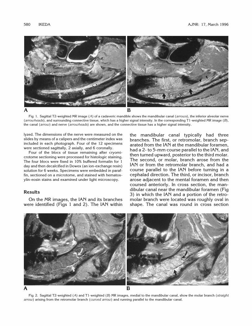
Fig 1. Sagittal T2-weighted MR image (A) of a cadaveric mandible shows the mandibular canal (arrows), the inferior alveolar nerve(arrowheads), and surrounding connective tissue, which has a higher signal intensity. In the corresponding T1-weighted MR image (B),the canal (arrow) and nerve (arrowheads) are shown, and the connective tissue has a higher signal intensity.
580 IKEDA AJNR: 17, March 1996
lyzed. The dimensions of the nerve were measured on theslides by means of a calipers and the centimeter index wasincluded in each photograph. Four of the 12 specimenswere sectioned sagittally, 2 axially, and 6 coronally.
Four of the blocs of tissue remaining after cryomi-crotome sectioning were processed for histologic staining.The four blocs were fixed in 10% buffered formalin for 1day and then decalcified in Dowex (an ion-exchange resin)solution for 6 weeks. Specimens were embedded in paraf-fin, sectioned on a microtome, and stained with hematox-ylin-eosin stains and examined under light microscopy.
Results
On the MR images, the IAN and its branches
were identified (Figs 1 and 2). The IAN withinthe mandibular canal typically had threebranches. The first, or retromolar, branch sep-arated from the IAN at the mandibular foramen,had a 2- to 5-mm course parallel to the IAN, andthen turned upward, posterior to the third molar.The second, or molar, branch arose from theIAN or from the retromolar branch, and had acourse parallel to the IAN before turning in acephalad direction. The third, or incisor, brancharose adjacent to the mental foramen and thencoursed anteriorly. In cross section, the man-dibular canal near the mandibular foramen (Fig3) in which the IAN and a portion of the retro-molar branch were located was roughly oval inshape. The canal was round in cross section
Fig 2. Sagittal T2-weighted (A) and T1-weighted (B) MR images, medial to the mandibular canal, show the molar branch (straightarrow) arising from the retromolar branch (curved arrow) and running parallel to the mandibular canal.

near the middle of the canal (Fig 4). The greaterdiameter of the canal averaged 4.1 mm (SD,0.5 mm) near the mandibular foramen. The av-erage diameter of the canal was 3.4 mm (SD,0.5 mm) in the middle of the canal. The man-dibular canal contained the IAN, the inferior al-veolar artery, loose connective tissue, andsometimes a portion of the retromolar or molarbranch of the IAN. The IAN was oval or roundand, on average, 2.2 mm (SD, 0.4 mm) in di-ameter. The inferior alveolar artery was identi-fied parallel to the nerve in all cases. It was inthe inferior portion of the mandibular canal nearthe mandibular foramen. Half the time it waslocated in the lateral inferior portion and half thetime in the medial inferior portion. In the middleof the canal, it was located in the medial supe-rior portion of the canal (Fig 4). The arteryaveraged 0.7 mm (SD, 0.2 mm) in diameter.The distance between the nerve and the nearestteeth ranged from 6 mm to 7 mm at the secondmolar.The IAN on histologic section was inhomoge-
neous. The peripheral sheath (epineurium) ofthe nerve had a homogeneous fibrous structure.In the epineurium, the two to eight axon bundles
Fig 3. Coronal MR image at 3 T near the mandibular foramenin another cadaver illustrates the inferior alveolar nerve (straightarrow) and retromolar branch (curved arrow) in the mandibularcanal.
Fig 4. Comparison of a coronal MR image (1500/60/4) obtained at 3 T (A) with the corresponding cryomicrotome section (B) andmagnification of the section at midcanal level (C). In the MR image, the osseous margins of the mandibular canal (curved arrow), theartery (open arrow), and the nerve (straight arrow) are seen. Within the nerve the axon bundles (arrowheads) and the sheath areidentified. In the cryomicrotome sections, the osseous margin of the canal (curved arrow), the artery (open arrow), the nerve, and theaxon bundles (arrowheads) are shown.
AJNR: 17, March 1996 MANDIBULAR CANAL 581
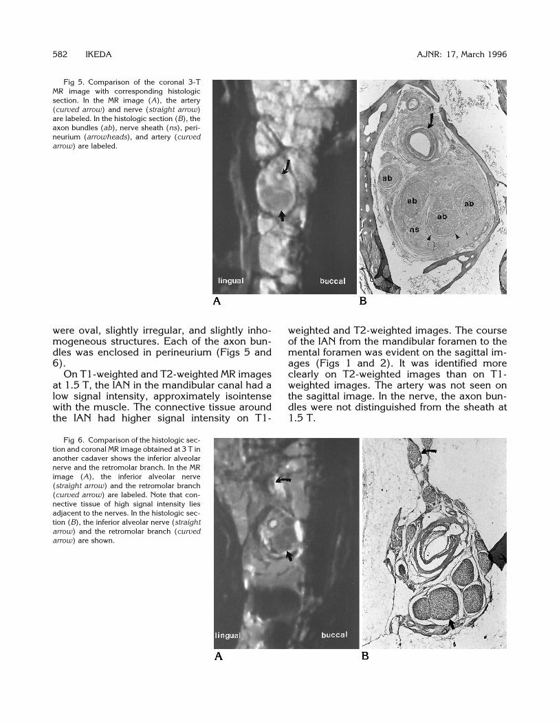
Fig 5. Comparison of the coronal 3-TMR image with corresponding histologicsection. In the MR image (A), the artery(curved arrow) and nerve (straight arrow)are labeled. In the histologic section (B), theaxon bundles (ab), nerve sheath (ns), peri-neurium (arrowheads), and artery (curvedarrow) are labeled.
582 IKEDA AJNR: 17, March 1996
1.5 T.
were oval, slightly irregular, and slightly inho-mogeneous structures. Each of the axon bun-dles was enclosed in perineurium (Figs 5 and6).On T1-weighted and T2-weighted MR images
at 1.5 T, the IAN in the mandibular canal had alow signal intensity, approximately isointensewith the muscle. The connective tissue aroundthe IAN had higher signal intensity on T1-
weighted and T2-weighted images. The courseof the IAN from the mandibular foramen to themental foramen was evident on the sagittal im-ages (Figs 1 and 2). It was identified moreclearly on T2-weighted images than on T1-weighted images. The artery was not seen onthe sagittal image. In the nerve, the axon bun-dles were not distinguished from the sheath at
Fig 6. Comparison of the histologic sec-tion and coronal MR image obtained at 3 T inanother cadaver shows the inferior alveolarnerve and the retromolar branch. In the MRimage (A), the inferior alveolar nerve(straight arrow) and the retromolar branch(curved arrow) are labeled. Note that con-nective tissue of high signal intensity liesadjacent to the nerves. In the histologic sec-tion (B), the inferior alveolar nerve (straightarrow) and the retromolar branch (curvedarrow) are shown.

Fig 7. Coronal MR image obtained at 3T near the mandibular foramen illustratesthe inferior alveolar nerve (straight arrow)and the molar branch (arrowhead) in themandibular canal and the retromolarbranch outside the canal (curved arrow),distal to its branching from the inferior al-veolar nerve. The high signal intensity inthe canal is related to the lumen of theartery.
Fig 8. Coronal MR image obtained at 3T posterior to the third molar illustrates theretromolar branch (arrows) exiting fromthe mandibular canal surrounded by con-nective tissue with a high signal intensity.
AJNR: 17, March 1996 MANDIBULAR CANAL 583
On the images acquired at 3 T (1500/60), theIAN was distinguished from the surroundingconnective tissue of higher signal intensity. Inthe connective tissue, the inferior alveolar arterycould be found as a low-signal-intensity struc-ture with a higher signal intensity in the lumen.In the IAN, the axon bundles appeared as smallirregularly shaped structures of lower signal in-tensity than that of the nerve sheath. The nervesheath, which encircled the axon bundles, had ahigh signal intensity, comparable to bone mar-row (Figs 5, 7, and 8).
Discussion
The cadaveric studies of the mandibular ca-nal can be extrapolated to clinical imaging withsome limitations. Postmortem, the contrast be-tween tissues changes on MR images. Alanen etal (9) showed that a rat muscle stored in arefrigerator at 68C had a significantly shorter T1signal 1 day after death, which returned to base-line levels within 4 days after death. Since in ourstudy the cadaver was stored several days at2208C, the postmortem changes are probablynot a significant factor. Freezing of cadaverictissue does not change the anatomic relation-ships markedly. In freezing, the volume of tissueis changed by up to 7%; however, the volumechange is most likely reversed by thawing forMR imaging (10). Since we used an experimen-tal coil and scanner, we could demonstrate
more detail in the mandibular canal than can beachieved clinically at the moment.The transient neurologic disturbance of sen-
sation in the lip and chin that follows tooth ex-traction in some cases presumably representsedema or damage to the IAN (2). An MR studyof the mandible may reveal the anatomic rela-tionships of the nerve and the teeth in the man-dible and may help determine the risk of injuryto the nerve from extraction. The location of thecanal suggests that tooth extraction may dam-age either the artery or nerve. MR imaging of theIAN may help determine the cause of anesthe-sia after dental extraction.In earlier studies of the nerve, variations of the
IAN have been described. Previous authorshave reported that the IAN divided into twobranches, one supplying the molar, premolar,and canine teeth and the other the incisor teeth(8, 11, 12). Some authors described the IAN asdividing in the mandibular foramen, with theretromolar branch passing through a foraminain the retromolar fossa (13, 14). Schejtman et al(15) named this the mandibular retromolar ca-nal. We found, as Hosaka (8) reported, that theIAN divided into three major branches in themandibular canal, the ramus retromolaris, therami molares, and the ramus incisivus. We alsofound that the artery in the mandibular canaloccupied the medial superior portion of the ca-nal near the mental foramen, in agreement withsome authors (16–18). Like Mozsary and Syers

(19), we found that there are 2 to 8 fascicles perIAN, not 6 to 18, as others reported (20).Some authors report that tumor invades
along the IAN because the nerve is not tightlyconfined within the canal and foramen. There-fore, tumor spread into the canal may obliteratethe high signal intensity of the connective tissue(21, 22). Our histologic findings that there isroom between the IAN and the canal (Figs 3Band 4B) is supportive of this observation. Theappearance of the canal in cases with tumorinvolvement should be studied. MR imagingmay be useful in the diagnosis of tumor infiltra-tions of the IAN.Another application of MR imaging of the IAN
may be to facilitate a surgical anastomosis ofthe IAN. MR imaging may help in the selectionof a donor nerve with similar fascicular size andpatterns to the host nerve (20) and in the deter-mination of the length of the nerve segment thatis damaged.
Conclusion
The IAN can be shown effectively by MR im-aging. Imaging the IAN and the artery with MRmay help in determining the risk of injury to thenerve from tooth extraction, in diagnosing neo-plastic infiltration in cases of metastatic carci-noma, and in facilitating microsurgery on theIAN.
References1. Kipp DP, Goldstein BH, Weiss WW. Dysesthesia after mandibular
third molar surgery: a retrospective study and analysis of 1377surgical procedures. J Am Dent Assoc 1980;100:185–192
2. Osborn TP, Frederickson G, Small IA, Torgerson TS. A prospec-tive study of complications related to mandibular third molarsurgery. J Oral Maxillofac Surg 1985;43:767–769
3. Horowitz SH. Isolated facial numbness: clinical significance andrelation to trigeminal neuropathy. Ann Int Med 1974;80:49–53
4. Stockdale CR. The relationship of the roots of mandibular thirdmolars to the inferior dental canal. Oral Surg Oral Med Oral Pathol1959;12:1061–1072
584 IKEDA
5. Littner MM, Kaffe I, Tamse A, Dicapua P. Relationship between theapices of the lower molars and mandibular canal: a radiographicstudy. Oral Surg Oral Med Oral Pathol 1986;62:595–602
6. Abrahams JJ. Anatomy of the jaw revisited with a dental CTsoftware program. AJNR Am J Neuroradiol 1993;14:979–990
7. Feifel H, Reidiger D, Gustorf-Aeckerle R. High resolution com-puted tomography of the inferior alveolar and lingual nerves.Neuroradiology 1994;36:236–238
8. Hosaka N. The anatomical study of the submaxillary nerve inJapanese cadavers: the intra-mandibular course of the inferioralveolar nerve (in Japanese). Shikagakuho J Tokyo Dent Col Soc1960;60:255–283
9. Alanen AM, Parkkola RK, Lillsunde IGV, et al. The effects of themethod of death and lapsed time on proton relaxation time T1 inautopsied muscle samples. Invest Radiol 1993;28:529–532
10. Pech P, Bergstrom K, Rauschning W, Haughton VM. Attenuationvalues, volume changes and artifacts in tissue due to freezing.Acta Radiol 1987;28:779–782
11. Olivier E. The inferior dental canal and its nerve in the adult. BrDent J 1928;49:356–358
12. Starkie C, Stewart D. The intra-mandibular course of the inferiordental nerve. J Anat 1931;65:319–323
13. Dieck W, Fujita T. Die Nerven der Kiefer und des Zahnfleischesbeim Menschen mit vergleichsuntersuchung der verhaltnissebeim Hunde (in German). Gegenbaurs Morph Jahrb 1935;76:570–588
14. Carter RB, Keen EN. The intramandibular course of the inferioralveolar nerve. J Anat 1971;108:433–440
15. Schejtman R, Devoto FCH, Arias NH. The origin and distributionof the elements of the human mandibular retromolar canal. ArchOral Biol 1967;12:1261–1267
16. Oikarinen VJ. The inferior alveolar artery. Suom HammaslaakToim 1965;61(Suppl 1):1–131
17. Poirot G, Delattre JF, Palot C, Flament JB. The inferior alveolarartery in its bony course. Surg Radiol Anat 1986;8:237–244
18. Zoud K, Doran GA. Microsurgical anatomy of the inferior alveolarneurovascular plexus. Surg Radiol Anat 1993;15:175–179
19. Mozsary PG, Syers CS. Microsurgical correction of the injuredinferior alveolar nerve. J Oral Maxillofac Surg 1985;43:353–358
20. Svane TJ, Wolford LM, Milam SB, Bass RK. Fascicular character-istics of the human inferior alveolar nerve. J Oral Maxillofac Surg1986;44:431–434
21. Harris CP, Baringer JR. The numb chin in metastatic cancer.WestJ Med 1991;155:528–531
22. Matzko J, Becker DG, Phillips CD. Obliteration of fat planes byperineural spread of squamous cell carcinoma along the inferioralveolar nerve. AJNR Am J Neuroradiol 1994;15:1843–1845
AJNR: 17, March 1996