multipath routing optimization in wireless mesh...
TRANSCRIPT

Multipath Routing Optimization inWireless Mesh Networks
By
Faiza Iqbal
2009-NUST-TfrPhD-CSE-28
Supervisors
Dr. Muhammad Younus Javed
NUST College of E&ME
Dr. Anjum Naveed
NUST SEECS
A thesis submitted in partial fulfillment of the requirements for the degree
of Doctor of Philosophy of Science in Computer Software Engineering
(PhD)
In
NUST College oF Electrical and Mechanical Engineering,
National University of Sciences and Technology (NUST),
Islamabad, Pakistan.
(May 2015)

Approval
It is certified that the contents and form of the thesis entitled “Multipath
Routing Optimization in Wireless Mesh Networks” submitted by
Faiza Iqbal have been found satisfactory for the requirement of the degree.
Advisor: Dr. Muhammad Younus Javed
Signature:
Date:
Committee Member 1: Dr. Khalid Iqbal
Signature:
Date:
Committee Member 2: Dr. Saad Rehman
Signature:
Date:
Committee Member 3: Dr. Hasan Islam (External)
Signature:
Date:
i

Certificate of Originality
I hereby declare that this submission is my own work and to the best of my
knowledge it contains no materials previously published or written by another
person, nor material which to a substantial extent has been accepted for the
award of any degree or diploma at NUST CEME or at any other educational
institute, except where due acknowledgement has been made in the thesis.
Any contribution made to the research by others, with whom I have worked
at NUST CEME or elsewhere, is explicitly acknowledged in the thesis.
I also declare that the intellectual content of this thesis is the product
of my own work, except for the assistance from others in the project’s de-
sign and conception or in style, presentation and linguistics which has been
acknowledged.
Author Name: Faiza Iqbal
Signature:
ii

Acknowledgment
First and Foremost, praises to Almighty Allah for enabling me to undertake
and complete this task. Without His help, it would have been impossible for
me to achieve this milestone.
I am highly thankful to my supervisor, Brig. Dr. Muhammad Younus
Javed, for his continuous guidance and valuable suggestions, especially for
the provision of all kinds of facilities throughout my thesis work. I am deeply
beholden to my co-supervisor, Dr. Anjum Naveed, this thesis would not have
been possible without his expert guidance and constant motivational support.
I would like to thank my GEC members, Dr. Khalid Iqbal, Dr. Hasan Islam
and Dr. Saad Rehman for their valuable time and comments on my thesis. I
would like to express my gratitude to Dr. Shoab A. Khan and Dr. Muazzam
A. Khan for their valuable suggestions. I am grateful to HEC and NUST for
providing me research funding through HEC indigenous scholarship scheme.
I am greatly thankful to SEECS Baltoras and CERN lab members, Kashif
Sattar, M. Zeeshan, Umar Ahmad, Madiha Wahid, Aliya Awais for their help
and valuable discussions. I would like to thank everyone who have helped me
in any way towards the successful completion of this thesis. Special thanks
to my EME hostel mates and friends Nosheen, Tahira, Sameera, Saeeda,
Ume-Hani, Maham, Lubna, Samra and to all those who have motivated me
during struggling days.
I am highly indebted to my parents, sisters and brothers for their tremen-
dous moral support and uncountable prayers throughout my studies. I dedi-
cate this achievement to my father, Muhammad Iqbal, who encouraged and
motivated me until his last breath. I am eternally grateful to my husband for
his support and encouregment. And finally a special mention to Abdullah,
you are an amazing kid.

Author’s Publications
• F. Iqbal, M. Y. Javed and M. J. Iqbal, Performance Analysis of Single
and Multipath Routing in Wireless Mesh Networks, in Proceedings of
7th International Conference on Computing and Convergance Technol-
ogy (ICCCT), December 2012, pp-55-59. [1]
• F. Iqbal, M. Y. Javed and A. Naveed, Interference-aware Multipath
Routing in Wireless Mesh Networks, EURASIP Journal of Wireless
Communication and Networking, 2014, 2014:140, impact factor:0.80. [2]
• F. Iqbal, M. Y. Javed and M. J. Iqbal, Diversity based Review of
Multipath Routing Metrics of Wireless Mesh Networks, in proceeding
of IEEE INMIC, December 2014, pp-320-325 [3]
• F. Iqbal, M. Y. Javed and A. Naveed, Wireless Interference Models:
An Analytical View. Journal paper, work in progress.
• F. Iqbal, M. Y. Javed and A. Naveed, Interference Mitigation us-
ing Capacity Adjusted Multipath Routing in Wireless Mesh Networks.
Journal paper, work in progress.

Abstract
Multipath routing provides load balancing and fault tolerance by employing
multiple paths to destination. The inherent mesh infrastructure of IEEE
802.11 based wireless mesh networks provide added support to construct mul-
tiple robust paths. However, based on geometric locations of wireless nodes,
neighbourhood interference and channel contention, create challenges for mul-
tipath routing schemes. A large body of research has been carried out to
maximize aggregate end-to-end throughput using multipath routing; however,
interference has not been accurately modelled in majority of the work. Based
on the relative location of transmitters and receivers, interfering links can be
categorized as coordinated and non-coordinated. Compared to coordinated in-
terference, information asymmetric non-coordinated interference introduces
bottleneck links and significantly reduces the aggregate throughput. The im-
pact of this interference is even observed on links several hops away. The
objective of this thesis is to improve network throughput by exploiting redun-
dant mesh infrastructure of wireless mesh network using multipath routing
which mitigates non-coordinated interference with priority.
We propose Interference Avoidance based Multipath Routing Linear Program-
ming (IAMR-LP) optimization model with an objective to maximize end-to-
end throughput by using multiple available paths, considering coordinated and
non-coordinated interference. It employs topology control to avoid bottleneck
links which are suffering from severe non-coordinated interference. The model
aims at selecting a subset of quality paths for each flow so that the aggregate
end-to-end throughput is maximized. Selection of paths is constrained by per
link capacity and interference at each link. The simulation throughput is 89%
of the throughput achieved using numerical solution which shows the effective-
ness of the model. Based upon the results of this model as baseline, we pro-
v

vi
pose an Adaptive Multipath Routing Approach with Topology Control (AM-
RTC) that develops a multipath routing strategy to achieve better end-to-end
throughput by purging badly affected non-coordinated links during path con-
struction procedure. Extensive simulation-based evaluation shows that AM-
RTC outperforms the existing schemes in improving the network throughput,
by upto a factor of 1.68. Next, we propose Interference Mitigation based
Multipath Routing Mixed Integer Nonlinear Programming (IMMR-MINLP)
model which avoids the link elimination approach of AMRTC and adjusts the
flow rates of links to reduce the impact of multilevel non-coordinated interfer-
ence. The numerical solution to the optimization problem generates multiple
paths for flows, resulting in optimal network throughput for a given network
and input traffic load. The generated paths of the numerical solution are then
fed in OPNET to simulate respective network instances. The evaluations of
simulation with IMMR-MINLP model shows the effectiveness of the model
which achieves upto 91% of the optimal aggregate network throughput. The
comparison of the fairness index of IMMR-MINLP with existing schemes
show its effectiveness in fair distribution of throughput among multiple flows.
Finally, the performance improvement of IMMR-MINLP model is compared
with LMX:M3F, MRAC, and ETT in terms of packet loss ratio, end-to-end
delay and link utilization.

Table of Contents
1 Introduction 1
1.1 Wireless Mesh Networks . . . . . . . . . . . . . . . . . . . . . 3
1.1.1 WMN Architecture . . . . . . . . . . . . . . . . . . . . 4
1.1.2 Characteristics of WMN . . . . . . . . . . . . . . . . . 6
1.2 Wireless Interference: Research Challenges . . . . . . . . . . . 7
1.3 Routing in WMN: Issues and Challenges . . . . . . . . . . . . 10
1.3.1 Research Challenges of Multipath Routing . . . . . . . 11
1.4 Research Contribution . . . . . . . . . . . . . . . . . . . . . . 12
1.5 Thesis Organization . . . . . . . . . . . . . . . . . . . . . . . . 13
2 Literature Review 15
2.1 Interference in Wireless Networks . . . . . . . . . . . . . . . . 15
2.1.1 Interference Models . . . . . . . . . . . . . . . . . . . . 16
2.2 Capacity Estimation Approaches . . . . . . . . . . . . . . . . 18
2.3 Routing Metrics of Wireless Mesh Network . . . . . . . . . . . 20
2.3.1 Single-radio Routing Metrics . . . . . . . . . . . . . . . 20
2.3.2 Multi-radio Routing Metrics . . . . . . . . . . . . . . . 21
2.3.3 Multipath Routing Approaches . . . . . . . . . . . . . 24
2.4 Interference Mitigation Schemes-Joint Approaches . . . . . . . 25
2.4.1 Routing and Channel Assignment . . . . . . . . . . . . 25
2.4.2 Routing and Topology/Power Control . . . . . . . . . . 27
2.5 Summary . . . . . . . . . . . . . . . . . . . . . . . . . . . . . 30
3 Analysis and Design 31
3.1 Introduction . . . . . . . . . . . . . . . . . . . . . . . . . . . . 31
3.2 Interference Model Analysis . . . . . . . . . . . . . . . . . . . 32
vii

TABLE OF CONTENTS viii
3.2.1 Interference Classification Based on Asymmetric Model 34
3.3 Empirical Comparison of Coordinated and Non-Coordinated
Interference Relationships . . . . . . . . . . . . . . . . . . . . 38
3.4 Multilevel Non-Coordinated Interference Dependencies . . . . 40
3.5 Impact of Capacity Adjustment on Bottleneck Links . . . . . 43
3.6 Impact of Number of Paths on Aggregate Throughput . . . . 45
3.7 Selection of Good Quality Paths . . . . . . . . . . . . . . . . . 46
3.8 Research Gap . . . . . . . . . . . . . . . . . . . . . . . . . . . 48
3.9 Summary . . . . . . . . . . . . . . . . . . . . . . . . . . . . . 50
4 Interference Avoidance based Multipath Routing 51
4.1 Introduction . . . . . . . . . . . . . . . . . . . . . . . . . . . . 51
4.2 Interference Avoidance based Multipath Routing–Problem For-
mulation . . . . . . . . . . . . . . . . . . . . . . . . . . . . . . 52
4.2.1 Network Model . . . . . . . . . . . . . . . . . . . . . . 53
4.2.2 Interference Model . . . . . . . . . . . . . . . . . . . . 53
4.2.3 Assumptions . . . . . . . . . . . . . . . . . . . . . . . . 54
4.3 Linear Program Formulation . . . . . . . . . . . . . . . . . . . 55
4.3.1 Decision Variables . . . . . . . . . . . . . . . . . . . . 55
4.3.2 Constraints Set . . . . . . . . . . . . . . . . . . . . . . 55
4.3.3 Objective Function . . . . . . . . . . . . . . . . . . . . 57
4.4 LP Model Validation . . . . . . . . . . . . . . . . . . . . . . . 58
4.4.1 Comparison of Per-Flow Throughput-LPModel vs OP-
NET Simulations . . . . . . . . . . . . . . . . . . . . . 59
4.4.2 Comparision of Average Throughput with Variable Node
Density-LPModel vs OPNET . . . . . . . . . . . . . . 61
4.4.3 Comparison of Average Throughput with Constant Node
Density-LPModel vs OPNET . . . . . . . . . . . . . . 61
4.5 Summary . . . . . . . . . . . . . . . . . . . . . . . . . . . . . 63
5 Adaptive Multipath Routing with Topology Control 64
5.1 Introduction . . . . . . . . . . . . . . . . . . . . . . . . . . . . 64
5.2 AMRTC - Adaptive Multipath Routing with Topology Control 65
5.2.1 AMRTC-Topology Control Algorithm . . . . . . . . . . 66

TABLE OF CONTENTS ix
5.2.2 AMRTC-Multipath Routing Algorithm . . . . . . . . . 66
5.3 Path Construction Comparison of LP Model and AMRTC . . 68
5.4 Performance Evaluations . . . . . . . . . . . . . . . . . . . . . 73
5.4.1 Experimental Setup . . . . . . . . . . . . . . . . . . . . 73
5.4.2 Unipath Vs. Multipath Routing . . . . . . . . . . . . . 74
5.4.3 Offered Traffic Load and End-to-End Throughput . . . 76
5.4.4 Length and Number of Paths . . . . . . . . . . . . . . 79
5.4.5 End-to-end Delay . . . . . . . . . . . . . . . . . . . . . 81
5.4.6 Impact of Increasing Node Density . . . . . . . . . . . 81
5.5 Summary . . . . . . . . . . . . . . . . . . . . . . . . . . . . . 84
6 Interference Mitigation based Multipath Routing 85
6.1 Introduction . . . . . . . . . . . . . . . . . . . . . . . . . . . . 85
6.2 Interference Mitigation based Multipath Routing – Problem
Formulation . . . . . . . . . . . . . . . . . . . . . . . . . . . . 86
6.2.1 Network and Interference Model . . . . . . . . . . . . . 86
6.3 MINLP Program Formulation . . . . . . . . . . . . . . . . . . 87
6.3.1 Decision Variables . . . . . . . . . . . . . . . . . . . . 87
6.3.2 Constraints Set . . . . . . . . . . . . . . . . . . . . . . 88
6.3.3 Objective Function . . . . . . . . . . . . . . . . . . . . 90
6.4 Model Validation . . . . . . . . . . . . . . . . . . . . . . . . . 91
6.4.1 Aggregate and Average Per-Flow Throughput . . . . . 93
6.4.2 Offered Traffic Load and End-to-End Throughput . . . 95
6.4.3 Length and Number of Paths . . . . . . . . . . . . . . 96
6.5 Evaluations . . . . . . . . . . . . . . . . . . . . . . . . . . . . 97
6.5.1 Experimental Results . . . . . . . . . . . . . . . . . . . 98
6.5.2 Impact of Increasing Demand on Bandwidth Utilization 98
6.5.3 Comparison of Bandwidth Blocking Ratio (BBR) . . . 99
6.5.4 Impact of Increasing Traffic Demand on Link Utilization101
6.5.5 Impact of Increasing Traffic Demand on Packet Loss
Ratio . . . . . . . . . . . . . . . . . . . . . . . . . . . . 102
6.5.6 Impact of Increasing Traffic Demand on End-to-End
Delay . . . . . . . . . . . . . . . . . . . . . . . . . . . 103
6.6 Summary . . . . . . . . . . . . . . . . . . . . . . . . . . . . . 104

TABLE OF CONTENTS x
7 Conclusion and Future Work 105

List of Figures
1.1 An Example WMN architecture . . . . . . . . . . . . . . . . . 5
1.2 Transmission and carrier sensing range of a mesh node. . . . . 8
3.1 Example illustrating difference between various Interference
models . . . . . . . . . . . . . . . . . . . . . . . . . . . . . . . 33
3.2 Topology showing Coordinated Interference(inset figure shows
two-flow CO interactions) . . . . . . . . . . . . . . . . . . . . 35
3.3 Topology showing Information Asymmetric Non-Coordinated
Interference(inset Figure shows two-flow IA interactions) . . . 36
3.4 Topology showing Near Hidden Non-Coordinated Interference(inset
Figure shows two-flow NH interactions) . . . . . . . . . . . . . 37
3.5 Topology showing Far Hidden Non-Coordinated Interference(inset
Figure shows two-flow FH interactions) . . . . . . . . . . . . . 38
3.6 Impact of increasing number of coordinated interference on
average per-link and aggregate throughput . . . . . . . . . . . 39
3.7 Impact of non-coordinated interference in two flow topologies . 41
3.8 Impact of non-coordinated interference dependencies. . . . . . 42
3.9 Six Single-hop topologies, showing CO and multilevel non-
CO interference dependencies. (d is the distance while Tr is
transmission range) . . . . . . . . . . . . . . . . . . . . . . . . 43
3.10 Achievable per-flow throughput comparison of Six Single-hop
topologies with capacity adjustment of links . . . . . . . . . . 44
3.11 Multi-hop topology, showing multiple link-disjoint and node-
disjoint paths observing non-CO interference . . . . . . . . . . 46
xi

LIST OF FIGURES xii
3.12 Impact of increasing number of parallel paths on average flow
throughput. . . . . . . . . . . . . . . . . . . . . . . . . . . . . 47
3.13 Effectiveness of using fewer good quality paths vs. using all
alternate paths. . . . . . . . . . . . . . . . . . . . . . . . . . . 47
3.14 Block diagram of proposed and implemented models . . . . . . 50
4.1 Block diagram of Interferenc avoidance based Multipath rout-
ing LP model . . . . . . . . . . . . . . . . . . . . . . . . . . . 59
4.2 Comparison of per-flow throughput for Manhattan network-
LPmodel vs Opnet Simulation . . . . . . . . . . . . . . . . . 60
4.3 Impact of variable node density (Increased coordinated inter-
ference) on average throughput . . . . . . . . . . . . . . . . . 61
4.4 Impact of constant node density (variable number of nodes
and non-coordinated interference) on average flow throughput 62
5.1 Flow chart of AMRTC algorithm . . . . . . . . . . . . . . . . 69
5.2 LP Model path construction . . . . . . . . . . . . . . . . . . . 70
5.3 AMRTC path construction . . . . . . . . . . . . . . . . . . . . 71
5.4 Performance Evaluation of AMRTC . . . . . . . . . . . . . . . 75
5.5 Fairness Constraint Impact . . . . . . . . . . . . . . . . . . . . 80
5.6 End-to-end Delay . . . . . . . . . . . . . . . . . . . . . . . . . 82
5.7 Impact of increasing no. of nodes (with constant node density)
on average throughput . . . . . . . . . . . . . . . . . . . . . . 83
6.1 Block diagram of MINLP model . . . . . . . . . . . . . . . . . 92
6.2 Aggregate and Average per-flow Throughput Comparison . . . 94
6.3 Impact of Traffic load on Network Throughput . . . . . . . . . 95
6.4 Multiple Paths and Path Length Comparison . . . . . . . . . 96
6.5 Comparison of Jain’s Fairness Index . . . . . . . . . . . . . . . 97
6.6 Impact of increasing demand on bandwidth utilization . . . . 99
6.7 Comaprision of Bandwidth Blocking Ratio . . . . . . . . . . . 100
6.8 Impact of increasing traffic demand on Link utilization . . . . 101
6.9 Impact of increasing traffic demand on Packet Loss Ratio . . . 102
6.10 Impact of increasing traffic demand on End to End Delay . . . 103

List of Tables
4.1 List of Notations for LP Model . . . . . . . . . . . . . . . . . 53
5.1 Simulation Parameters for AMRTC experiments . . . . . . . . 74
6.1 List of Notations for MINLP model . . . . . . . . . . . . . . . 87
6.2 Simulation Parameters for capacity adjusted Opnet evaluations 93
xiii

Chapter 1
Introduction
Over the last decade, the research on extending IP connectivity to the last
mile has received much attention yet it is still an open and challenging is-
sue. The researchers and practitioners have implemented different solutions
including end-to-end optical network and/or providing wireless access net-
work. However, most of these solutions require expensive installation of
fibre/wire and huge investment on the deployment of WiFi hotspot in urban
areas, hotels, airports and wilderness. Moreover, the environmental setting,
topographical constraints and social issues prevent the widespread coverage
for these access networks.
IEEE 802.11 based Wireless Mesh Networks (WMN) have emerged as a
promising architecture to provide last-mile Internet connectivity to fixed and
mobile users. The architecture of WMN usually comprises of mesh clients,
mesh routers and gateways. Mesh routers connect mesh clients with gate-
ways using multihop wireless links. Several deployment scenarios of WMN
are in practical use including deployment for coverage enhancement, in-door
deployment where Internet cabling is difficult, community wide deployment
such as university campuses and deployment in disaster struck areas. Be-
sides being easy to deploy, the redundant infrastructure of WMN provides
added support for multiple reliable paths. Their characteristics to dynami-
cally self-heal and self-organize, coupled with the ability to maintain mesh
connectivity with low set-up and maintenance cost made them valuable in
broad range of application domains. [4, 5]
1

CHAPTER 1. INTRODUCTION 2
Despite a number of worldwide WMN deployments and projects with
communications based on WMN [6–9], many research challenges exist that,
if addressed, can significantly improve the achievable throughput. In partic-
ular, given the broadcast nature of wireless medium, interference has signif-
icant impact on capacity of wireless links. Based on the relative location of
transmitters and receivers, interference can introduce bottleneck links in the
network which causes flow starvation and can significantly reduce the end-
to-end throughput. The impact of such interference is even observed on links
several hops away. In order to deal the impact of interference on the network
capacity, research studies have proposed different solutions related to routing
and topology control. Routing, the process of discovering best path in the
network, gives better results when coupled with topology control which is a
technique to modify the underlying network to reduce the interfering effects.
However, the accurate knowledge of interference and its effect on underlying
topology remains a challenging issue.
A combination of accurate interference estimation and interference avoid-
ance/mitigation technique is mandatory for acceptable network performance.
Accurate estimation of interference can lead to interference avoidance by
exploiting the inherent redundant infrastructure of WMN through efficient
routing and low interference path selection.The focus of this dissertation is
to exploit the mesh topology of WMN using multipath routing while avoid-
ing and/or mitigating interference through topology control and link capacity
adjustment techniques.
The rest of the chapter is organized as follows. Section 1.1 describes the
characteristics and topological details of WMN. In section 1.2, we have ex-
plained the wireless interference and its problems and challenges. Section 1.3
outlines the issues and challenges of routing, particularly of multipath rout-
ing, in WMN. Subsequently, in section 1.4, we have explained the research
contributions of this thesis. Finally, section 1.5 outlines the rest of the thesis
and concludes the chapter.

CHAPTER 1. INTRODUCTION 3
1.1 Wireless Mesh Networks
The emergence of Wireless Mesh Networks (WMN) has fulfilled the dream
of wide spread and seamless connectivity of Internet. Due to the simplicity
and low upfront cost, it has emerged as a key technology to dominate the
wireless networking in the coming years. Using multihop communication,
WMN makes use of existing technology to connect dozens or even hundreds
of devices to connect and communicate seamlessly. The mesh network com-
prises of mesh routers and mesh clients which are collectively referred to as
mesh nodes. These nodes can simultaneously function as host and router
which not only generate their own traffic but also relay packets of other
mesh nodes to their destinations. Any user device (mesh client), e.g. desk-
top PC, laptop, phones, PDAs can be directly connected to mesh router
using wireless network interface cards (NIC) or Ethernet cable. This feature
helps end-users to access internet anytime anywhere. Furthermore, the gate-
way/bridge functionality of mesh routers enable WMNs to integrate with a
number of existing wireless technologies e.g. wireless fidelity (WiFi), wireless
sensor network, worldwide interoperability for microwave access (WiMAX)
and cellular networks. Thus end-users can access the services of different
existing networks through an integrated WMN.
One of the significant characteristic of mesh networking is the ability
to dynamically self-configure and self-organize while maintaining mesh con-
nectivity. In addition, the capability of incremental deployment of mesh
nodes with low set-up and maintenance cost not only provides reliability and
robustness but also make them valuable in broad range of application do-
mains. Numerous applications like broadband home networking, community
networking, transportation systems, security and surveillance systems, build-
ing automation and enterprise networking are made functional by using the
mesh networking paradigm. One of the major reason for such a fast adaption
to WMN is its ease of deployment, i.e. all the required components for its
deployment are readily available from the existing technologies, for exam-
ple ad-hoc routing protocols, IEEE 802.11 MAC protocol, wired equivalent
privacy (WEP) security etc.
Despite all these characteristics, many research challenges exist which

CHAPTER 1. INTRODUCTION 4
prevent these multihop networks to achieve optimal performance. For in-
stance, applying existing ad-hoc routing protocols to WMN prevent it to
achieve better scalability. As the number of hops is increased, the through-
put starts decreasing which results in degraded performance of the network.
In the next subsections, we have explained the network architecture of WMN
and have listed its characteristics to distinguish it from the existing ad-hoc
networking paradigm.
1.1.1 WMN Architecture
The architecture of WMN, shown in Figure 1.1, consists of mesh routers,
mesh clients and gateways. Mesh routers (R1 to R5 in figure), are fixed traffic
aggregation points which forward traffic of each others towards gateways. In
addition to this conventional routing capability for gateway/repeaters, mesh
routers contain mesh networking functionality to support mesh connectiv-
ity. These are usually equipped with multiple interfaces on same or different
wireless technologies. Using multihop communication, mesh router is de-
signed to achieve same transmission range with lower transmission power as
compared to conventional wireless routers. Mesh router with gateway func-
tionality (G1-G5 in figure) are used to connect the network to the rest of
the internet. Mesh clients (c1 to c18 in figure) are user devices which benefit
from mesh networking to transfer information to their remote destinations.
Although gateway/bridge functionality is not present in mesh clients, but
these devices do contain some necessary mesh networking functions and can
be used to route information. Mesh client are equipped with one wireless
interface card and have much simpler hardware and software platform than
mesh routers. For example, mesh clients include laptops/desktop PC, PDAs,
Smartphone, Tablets, IP phones, RFID readers etc.
Based on the node functionality, the WMN architecture is classified into
three main groups:
Infrastructure (Backbone) Mesh: This type of WMN provides backbone
functionality for mesh clients and connects them to the rest of the networks.
In Figure 1.1, the router enclosed in big round circle represents infrastructure
mesh network which connects devices of different wireless access technologies

CHAPTER 1. INTRODUCTION 5
Figure 1.1: An Example WMN architecture

CHAPTER 1. INTRODUCTION 6
with each other. In figure, wired links are represented with solid lines whereas
dashed lines represent wireless links. With gateway/ bridge functionality, the
mesh router of infrastructure mesh provides wired connection to conventional
devices through Ethernet links. On the other hand, the clients which have
same radio technology as of mesh router can be directly connected with
it. For different radio technologies, base stations are used which connect to
mesh router through Ethernet to provide internet connection to their clients.
Infrastructure mesh is most commonly used in neighbourhood networking,
community networking and enterprise networking.
Client Mesh: In order to provide peer-to-peer networking, client meshing
is used. Client nodes are provided with routing functionality along with end-
user utilities. An example client mesh is formed in small square box on top
left corner of Figure 1.1. The devices establish multihop links to parcel the
packets to the required destination. Usually, this type of network is formed
by using same radio technology and mostly used to extend the coverage of
network in client domain.
Hybrid Mesh: This type is the combination of Client mesh and infrastruc-
ture mesh. Figure 1.1 represents an example hybrid mesh network. This is
the most commonly used mesh architecture due to its advantage to integrate
different wireless access technologies with client mesh domain.
1.1.2 Characteristics of WMN
In this subsection, we have listed some of those characteristics of WMN which
differentiate it from conventional ad-hoc networking paradigm.
Multihop Networking: The major objective of WMN is to provide ex-
tended coverage, without decreasing channel capacity, to existing wireless
access technologies. This is achieved by using multihop networking for es-
tablishing shorter link distances, with lesser interference and efficient fre-
quency re-use. This feature of WMN to provide non-line-of-sight (NLOS)
connectivity to end-user of different access technologies differentiates it from
conventional ad-hoc networking paradigm.
Self Healing, Self Forming, Self Configuring on top of Ad-hoc Networking:
Using ad-hoc networking, the capabilities of WMN to create flexible network

CHAPTER 1. INTRODUCTION 7
architecture, straightforward deployment and dynamic self-configuration, fault
tolerance and robust mesh connections, make them valuable in broad range
of application domains.
Integrated Wired/Wireless Access Technologies: In WMN, due to the sup-
port of backbone infrastructure and client mesh architecture, the end-user
can effortlessly access the Internet. Moreover, the integration of these archi-
tectures with existing wireless access technologies provide compatibility and
interoperability with a range of available technologies which is not available
in conventional ad-hoc networking paradigm.
Minimal or No Mobility: In WMN, the mesh routers are fixed nodes and
are usually installed on predetermined locations to provide better network
coverage. Mesh client can be fixed or mobile based on end-user requirements.
Thus, as compared to conventional ad-hoc networks, the mobility of mesh
nodes depend on the application requirements.
Minimum Power Consumption Constraints based on Mesh Nodes: In
WMN, mesh routers are usually provided with uninterrupted power sup-
ply and thus have no strict constraints regarding power consumption. Mesh
clients do require power efficient applications and protocols based on the
end-user services and utilities.
1.2 Wireless Interference: Research Challenges
This section explains wireless interference and its effects on the performance
of WMN. Based on these adverse effects, it highlights the existing research
challenges of interference in WMN. First, we have defined the terms trans-
mission and carrier sensing range.
Transmission Range: It is defined as the maximum distance between
wireless nodes u and v such that the transmission of packets from node u can
be successfully received at node v. This establishes a wireless link between
node u and node v when the two are operating on same channel. Figure 1.2,
represents the transmission range of a mesh router u with solid circle, thus
all nodes placed inside this circle are in the transmission range of node u.
Carrier Sensing Range: It is defined as the distance above transmission
range of node u where all other nodes can sense the radio transmission of

CHAPTER 1. INTRODUCTION 8
Figure 1.2: Transmission and carrier sensing range of a mesh node.
node u to v. In Figure 1.2, this distance is represented with dotted circle
around node u.
Based on these definitions, a wireless link l1(u1, v1), between transmitter
u1 to receiver v1, is said to be interfering with another wireless link l2(u2, v2)
if the distances between the alternative transmitter and receiver of these
links is less than the carrier sensing range and the two link are operating on
the same channel. In other words, wireless interference between two links
l1(u1, v1), l2(u2, v2) emerges when both links are transmitting simultaneously
in existence of the following two conditions:
i) d(u1, v2), d(u2, v1), d(v1, v2), d(u1, u2) < Rcs
ii) l1(u1, v1), l2(u2, v2) operating on Channel 1
The wireless interference depends on the traffic load of the interfering
links. In a set of n links operating on same channel, the transmission of a
particular link is successful only if all of the remaining n− 1 interfering links
are silent. One of the major research challenges of wireless interference is
the degraded network performance. Its direct impact on the throughput of
the wireless links can be observed with this example. Suppose a set of n
interfering links are operating on same channel having total channel capacity
of B Mbps. At an instant i, when all n links are operating simultaneously,

CHAPTER 1. INTRODUCTION 9
each link can achieve a channel capacity of up to B/n Mbps only if equal
sharing of channel capacity is assumed. The situation can be worst due to
collisions which results in the loss of transmission opportunities for active
transmitters. Thus interference has shown a profound impact on the achiev-
able network throughput. The major challenge for any routing scheme is to
properly account wireless interference to capture its effect.
Over the past decade, a number of unipath and multipath routing schemes
and protocols have been proposed [10–25]. Significant body of research has
used protocol model [14,20,25], physical model [20,26] or measurement based
models [12,27–34] for interference estimation. However, none of these models
and metrics accurately capture the impact of interference. Consequently, the
selected routing paths do not lead to optimal end-to-end throughput. The
basic reason for inaccuracy is the underlying assumption that all interfering
links have similar impact. In practice, this assumption does not hold and
relative location of the interfering links leads to different impact of interfer-
ence. Based on relative locations of transmitters and receivers, Garetto et
al. [35] have categorized interfering links into four categories.
According to the authors, two links are said to be coordinated interfer-
ing links if the transmitters of links are within carrier sensing range of each
other. These coordinated transmitters prevent each other from concurrent
transmissions, resulting in negligible packet collisions. On the other hand, if
transmitters of the two interfering links are not within carrier sensing range
of each other, three additional categories of interference – Near Hidden, Far
Hidden and Information Asymmetric – are possible. We collectively refer to
the interference caused by these categories as non-coordinated interference.
In case of non-coordinated interfering links, the two transmitters cannot
sense the transmissions of each other. This results in increased probability
of collisions. Particularly, among non-coordinated interference, information
asymmetric is the most detrimental interference in terms of unfair channel
sharing and end-to-end throughput performance [35]. The asymmetric chan-
nel view of the two information asymmetric interfering links allow one link
to achieve its maximum throughput while the other link starves. Conse-
quently, bottleneck links are introduced in the network, leading to reduced
end-to-end throughput. Therefore, an efficient routing scheme is required,

CHAPTER 1. INTRODUCTION 10
which considers coordinated as well as asymmetric non-coordinated inter-
actions of transmitters and receivers during path construction procedure to
avoid such bottleneck links. In this thesis, our main concern is to observe
and evaluate the asymmetric impact of interference and to improve network
performance by non-coordinated interference minimization using multipath
routing approach.
1.3 Routing in WMN: Issues and Challenges
Routing is considered as a challenging research issue in wireless multihop
networks because of its limited bandwidth and in-built interference as com-
pared to wired networks. The inherent multi-access and broadcast nature
of wireless medium coupled with traffic variations and resource contention
poses further challenges on selecting efficient routing patterns. To satisfy
application demands and achieve better network performance, the need is to
design a robust routing scheme which not only use limited wireless medium
efficiently but also tackle in-built wireless interference.
This section lists the routing characteristics, with respect to wireless mesh
networks, which must be considered while devising routing schemes. These
properties differentiate WMN from conventional ad-hoc networks and are
always considered as the basic issues and challenges for designing efficient
and robust routing approaches:
Network Architecture: The routing approaches are designed based on the
underlying network topology. Although, the fixed backbone infrastructure
of WMN provides added support for efficient routing, but the unpredictable
wireless medium, inbuilt interference and mobile end-users pose challenges
for routing schemes.
Wireless Link Capacity: Due to the presence of surrounding interference,
the capacity of wireless link varies over time. It creates challenges for routing
schemes which inadvertently select low capacity links under severe interfer-
ence, thus results in degraded network performance.
Random Traffic Patterns: In WMN traffic flows from mesh routers to
gateways. The traffic generated from client mesh domain varies depending
upon end-user applications. Thus, in order to make efficient routing deci-

CHAPTER 1. INTRODUCTION 11
sions, routing schemes must consider these random traffic patterns.
Channel Diversity: Despite the fact that, in WMN, the availability of di-
verse channels per radio interface benefit the routing process but also create
challenges. The routing scheme must include efficient channel assignment
scheme to select better quality paths in order to reduce inter-node interfer-
ence and improve overall throughput.
Inter/Intra-Flow Interference: Due to the broadcast nature of wireless
medium in WMN, interference emerges between transmissions on even dis-
joint paths. Inter-flow interference appears when two neighbouring routers
on disjoint paths compete for the same busy channel. On the other hand,
intra-flow interference emerges when two neighbouring routers on the same
path share the same flow. This creates hidden and exposed node problems
(discussed in detail in chapter 3) and introduces a major challenge for routing
schemes.
1.3.1 Research Challenges of Multipath Routing
Based upon the mesh infrastructure of WMN, multiple paths can be formed
between source routers to gateways using multipath routing. The availability
of multiple paths to destination not only provides reliability and robustness
but can also be used for load balancing and fault tolerance. Using load
balancing approach of multipath routing, the traffic load can be split into
multiple paths to avoid congestion and bottleneck links. From the viewpoint
of fault tolerance, multipath routing gives route flexibility and resilience by
providing standby path on the event of primary path failure.
Despite these benefits of multipath routing, a number of research chal-
lenges exist. In case of fault tolerance, the use of multipath paths to destina-
tion creates redundant data at the end node. It creates overhead on the net-
work as well as on the sink node. Moreover, the selection of the number and
the quality of paths create major challenge for the routing schemes. Another
important issue is the emergence of interference from multiple paths of the
same flow. This limits the overall capacity of the network and may cause per-
formance degradation. Based upon these advantages and challenges, we have
devised an efficient approach of multipath routing which not only overcomes

CHAPTER 1. INTRODUCTION 12
these problems but also takes advantage from the availability of multiple
paths in mesh network to improve network performance.
1.4 Research Contribution
The following research hypothesis has made the basis of this thesis: The
end-to-end throughput of multi-hop wireless mesh network can be significantly
improved if multilevel asymmetric non-coordinated interference is mitigated
using multipath routing. Based upon this hypothesis, we have proposed mul-
tipath routing scheme which not only alleviates the multilevel effects of non-
coordinated Interference but also models the asymmetric impact of interfer-
ence on wireless links. To the best of our knowledge, no other work has been
done which explicitly addresses asymmetric non-coordinated interference us-
ing multipath routing. The following paragraphs summarize the research
contribution of this thesis.
We have analytically measured the impact of non-coordinated interfer-
ence at multiple levels of network topology. We have shown that how non-
coordinated interference surreptitiously creates bottleneck links several hops
away which consequently degrades the end-to-end throughput. Subsequently,
we have proved that the capacity adjustment of links under severe non-
coordinated interference can avoid the creation of bottleneck links and results
in improved end-to-end throughput. Moreover, we have demonstrated the ef-
fectiveness of using multiple but fewer quality paths in mitigating the impact
of coordinated and non-coordinated interference.
We have proposed an Linear programming (LP) based optimization model
for joint topology control and multipath routing. The objective of the model
is to maximize end-to-end throughput using multiple available paths, con-
sidering coordinated and non-coordinated interference. It employs topology
control to avoid bottleneck links which are suffering from severe asymmet-
ric non-coordinated interference. The model aims at selecting a subset of
quality paths for each flow such that the aggregate end-to-end throughput is
maximized. Selection of paths is constrained by per link capacity and inter-
ference at each link. Effectiveness of the model in accurately predicting the
end-to-end throughput is shown through simulations.

CHAPTER 1. INTRODUCTION 13
Based upon the results of LP model as baseline, we have proposed an
adaptive multipath routing approach with topology control (AMRTC) which
develops a multipath routing strategy to achieve better end-to-end through-
put by purging badly affected non-coordinated links during path construction
procedure. AMRTC is a two phase centralized scheme. The first phase of
AMRTC performs topology control by identifying and pruning the multilevel
non-coordinated interfering links. Resultant topology control graph is used in
the second phase where maximum available residual capacity paths to satisfy
the flow demands are selected. Extensive simulation-based evaluation is car-
ried out to study the effectiveness of the proposed scheme. The results show
that AMRTC can effectively mitigate the impact of coordinated as well as
asymmetric non-coordinated interference and can achieve good performance
under different scenarios.
Next, we propose Mixed Integer Nonlinear Programming (MINLP) based
optimization model which avoids the link elimination approach of AMRTC
and adjusts the flow rates of links to reduce the impact of multilevel asym-
metric non-coordinated interference. In this way the model ensures fairness
among flows while reducing asymmetric non-coordinated interference. The
interference mitigation step is achieved using adaptive link capacity adjust-
ments. The links which are causing severe asymmetric interference are made
to reduce their data rate to allow other links under severe asymmetric inter-
ference to achieve fair capacity share. Extensive simulation based evaluation
of the model is performed which shows the efficacy of the model.
1.5 Thesis Organization
The rest of the thesis is organized as follows:
Chapter 2 reviews existing literature and categorizes them into subsections
related to interference estimation models, interference mitigation-joint ap-
proaches, capacity estimation schemes, well-known existing routing metrics
and multipath routing approaches. The existing studies are compared with
the proposed approach of this thesis to highlight the difference.
Chapter 3 describes the motivation of this thesis. It analyses interference
models and highlights the difference between coordinated and non-coordinated

CHAPTER 1. INTRODUCTION 14
interference. It illustrates how asymmetric non-coordinated interference cre-
ates bottleneck links and influence end-end throughput during routing. It
shows that with careful link capacity adjustments, these bottleneck links can
be avoided. It also demonstrates that creating multiple but fewer quality
paths improve the overall throughput. Based on the motivational analysis.
the research gap of existing literature is identified.
Chapter 4 proposes an optimization model for joint topology control and mul-
tipath routing and presents an approach to avoid asymmetric non-coordinated
interference through topology control.
In Chapter 5, an adaptive multipath routing algorithm (AMRTC) has been
proposed which uses the findings of the optimization model. AMRTC is
a two phase centralized scheme which, in first phase, adjusts topology by
identifying and pruning multilevel non-coordinated interference and in second
phase forwards flows on multiple path of the resultant topology.
Chapter 6 extends AMRTC and presents Mixed Integer Nonlinear Program-
ming (MINLP) model based multipath routing with fair distribution of flows.
It eliminates multilevel asymmetric non-coordination interference through
link capacity adjustment approach which results in the removal of bottle-
neck links. This improves end-to-end throughput of flows by avoiding flow
starvation with fair flow distribution.
Finally, chapter 7 concludes the thesis and summarizes research findings and
open issues.

Chapter 2
Literature Review
In view of the large body of research conducted to address capacity estimation
and routing design problems of wireless mesh network, we have divided the
related literature into four broad sections. Section 2.1 presents an overview
of interference models and reviews interference estimation and measurement
schemes. Section 2.2 reviews the literature related to capacity estimation
techniques of wireless multihop networks. Section 2.3 surveys well-known
existing routing metrics of wireless mesh network and existing multipath
routing approaches. In section 2.4, we have categorized the existing schemes
based on interference mitigation.
2.1 Interference in Wireless Networks
Interference in wireless networks remains a main concern of researchers for
decades. Its impact in infrastructure based cellular networks is well re-
searched and documented (e.g. [36, 37]) whereas in wireless multihop net-
works, it still remains an open and unsettled issue. The main consequence of
interference is the reduction of capacity and throughput of wireless networks.
It is therefore necessary to understand interference models and relationships
with respect to links and paths to significantly reduce its effect. The following
subsections describe some of the existing interference models which are used
by most of the existing capacity estimation and throughput optimization
approaches. We explain these models to highlight their limitations in this
15

CHAPTER 2. LITERATURE REVIEW 16
area. Subsequently, we have described the Garettos model of interference [35]
which serves as the basis of the proposed approach of this thesis.
2.1.1 Interference Models
Considering the significant influence of interference on the performance of
wireless multihop networks, a number of interference models have been pro-
posed over the past decade [38–53]. In the following paragraphs, we have
reviewed existing interference models.
Protocol Interference Model: [45] This model states that the transmission
from node u to node v is successful only if any other node in the interference
range of v is not transmitting at the same time. The following two conditions
need to satisfy:
1. The distance d between transmitting node u and receiving node v is
less than the transmission range Tr i.e.
d(u, v) < Tr
2. All other nodes k, transmitting on the same channel is at a distance
d(k,v) such that:
d(k, v) > d(u, v)
This model is often considered as binary model or double disk model since
interference is considered to be developed at a certain constant distance from
transmitter and/or receiver.
Physical Interference Model: [45] This model states that the transmission
from node u to node v is successful only if Signal to Interference and Noise
Ratio (SINR) of node v is above a threshold value β. Let Tuv represent the
transmission power of u received at node v then communication between the
two node is successful iff:
Tuv/N+Σi∈I Tvi < β

CHAPTER 2. LITERATURE REVIEW 17
where N represents the background noise and I represents all the interfering
nodes in the range of receiver v transmitting at the same time. The authors
[54] have adopted this model to extend the SINR to probabilistic SINR which
consider SINR value lesser than threshold to predict successful transmission.
In [55], the authors have adopted SINR based Interference model to solve
the problem of optimal tree based structure of routing for multicasting in
multihop wireless networks. Considering the complexity involved in SINR
based interference model, the authors [56,57] have compared the physical and
protocol model in multihop wireless environment to reconcile the gap between
the two. Using reality check mechanism and simulation based measurement;
they have come to a conclusion that there is very negligible difference between
the two models in capturing the impact of interference. On the other hand, a
similar study has been performed in [52] to compare different physical layer
based interference models.
K- hop Interference Model: [58] This model states that two nodes at k-hop
distance cannot transmit at the same time. This is also referred as node-
exclusive interference model where any node cannot simultaneously transmit
or receive on two separate links.
Receiver Conflict Avoidance Model: [59] In this model, the transmission
between nodes u and v is regarded as successful if all interfering nodes of v
remain silent during the communication of u and v. This model is considered
as the generalized form of Protocol Model.
Transmitter-Receiver Conflict Avoidance Model: [59] In this model, the
transmission between nodes u and v is regarded as successful if and only if all
interfering nodes of both u and v remain silent during the communication.
This is achieved using the concept of handshake and acknowledgement like
RTS (Request-to-Send) and CTS (Clear-to-Send) in 802.11 networks.
Extended Protocol Model: [60]] This model states that two links l1(u1, v1),
l2(u2, v2) are said to be interfering if u2(or v2) is in the interference range of
u1(or v1). In other words, any of the following condition must satisfy:
d(u1, u2)<Rcs OR d(u1, v2)<Rcs OR d(u2, v1)<Rcs OR d(v1, v2)<Rcs
In recent studies, a number of routing and topology control schemes [14,61–
63] have adopted this interference model to capture the effect of interference

CHAPTER 2. LITERATURE REVIEW 18
on the network. Although, the extended protocol model accurately identifies
all interfering links but it is unable to capture the impact of interference
correctly based on the relative locations of the links. Garetto et al. [35]
proposed model of interference addresses this limitation.
Garettos Model of Interference: [35] This model has been extended from
Bianchis model [64] (which developed Markove model of IEEE 802.11 DCF
for single carrier sensing domain) for multiple carrier sensing domain of
single-radio single-channel multi-hop wireless network. Similar to extended
protocol model, the authors [35] identified two links l1(u1, v1), l2(u2, v2) in-
terfering if d(u1, u2), d(u1, v2), d(u2, v1), d(v1, v2) < Rcs. In addition, based
on the relative location and impact of interference, the model categorized
the links as Coordinated (CO), Near-Hidden (NH), Far-Hidden (FH) and
Information Asymmetric (IA). The last three categories FH, NH and IA,
grouped as non-Coordinated (non-CO) links, impose worst impact on net-
work throughput as compared to coordinated links. In next chapter, we have
given detailed explanation of these categories and their impact on network
throughput. An extension to this work has been presented by Razak et
al. [65, 66] which identifies seven more categories of interference but impact
of nearly all these categories fall in the already identified interfering relations
of Garettos model. Thus we have adopted Garettos model of interference for
our proposed scheme and renamed it as asymmetric interference model.
2.2 Capacity Estimation Approaches
The seminal and most influential work on capacity estimation of wireless net-
work is presented by Gupta and Kumar [45]. They proved that, for randomly
chosen destination of n nodes network each of which transmit Wbits/sec, the
maximum achievable throughput is Θ(W/√n log n). This can be achieved in
no more than Θ(W/√n) for optimally placed nodes, with optimal traffic
load and transmission range. Following this work, the authors [67] demon-
strated the achievable theoretical per node capacity of 802.11 MAC equal to
O(1/√n) for randomly placed n node network with random traffic pattern.
They argued that for n node multihop network, the per-hop nodal capacity
is O(n). With the addition of more nodes in the network, the number of

CHAPTER 2. LITERATURE REVIEW 19
hops of end-end routing path grows up, thus the average routing path length
becomes the spatial diameter of network O(√n). This makes the per node
throughput equal to O(n/√n)=O(1/
√n).
The capacity analysis of Wireless Mesh Networks (WMN) remains an
interesting issue among researchers over the last decade. An important study
related to capacity analysis of mesh network is presented in [?]. The study set
up relay nodes between source and destination and proved that for an infinite
node network, the achievable network capacity is O(log n). In mesh network
setting, where each node relays traffic to respective gateways, create gateways
to act as hot-spot [68]. The study shows that increasing the number of such
gateways makes the per-node capacity equal to O(1/n). In another study
[69], the authors prove that in WMN the achievable per node throughput is
O(1/δn) where the factor δ depends on hop-radius which, for larger network,
converge to 3. In the similar environment with directional antennas, the
authors [70] prove that the achievable capacity of WMN, for m = 2, is
O( logmθ
), and for m > 2 is O( logmθ2 log(1/θ)
) where m represents the number of
node antennas and θ represents beam width of antennas.
Considering multi-channel and multi-interface feature of WMN, the au-
thors [71] prove that the channel to interface ratio of a node has severe impact
on network capacity. It is shown that, in an arbitrary network with controlled
node location and traffic pattern, the network capacity tends to decrease if
the number interfaces of a node are lesser than the number of allocated chan-
nels. Whereas, in a network with random node location and traffic pattern,
single interface become sufficient to utilize multiple channels if number of
channels are scaled to O(log n) with channel bandwidth of W/c. In another
study [72], the authors have extended this to multichannel environment hav-
ing two types of channel assignment constraints namely adjacent assignment
and random assignment. In adjacent assignment constraint, achievable per
flow capacity is θ(W√
fcn logn
) where a node can switch between f randomly
chosen continuous channels out of c available channels. On the other hand,
the maximum achievable flow capacity of random assignment between f sub-
set channels is O(W√
Prnd
cnlogn) where Prnd=1− (1− f
c)(1− f
c−1)...(1− fc−f+1
).
In [50], the authors claim that random assignment of channels can attain the
same capacity as of unconstrained switching when f = Ω(√c).

CHAPTER 2. LITERATURE REVIEW 20
In recent year, a number of research studies have been conducted to pro-
pose wireless link quality estimation tools and metrics. In [73, 74], authors
have proposed Effective Link Capacity (ELC) estimation metric which can
provide an accurate picture of link condition to MAC layer. The authors [75]
present experimental evaluation of recently existing scheme of link capacity
estimation and propose multilayer capacity model which can be used for net-
work planning and measurement. A number of research studies [76,77] have
been proposed to develop capacity estimation tools. In [78], the authors have
developed a generic methodology for capacity analysis which can be applied
to a number of different network scenarios. They have considered different
capacity impacting parameters to develop an association to estimate the ca-
pacity of static and mobile network. Similar studies have been conducted
in [79,80]. In [81], authors have proposed an algorithm, based on the failure
probability of packet delivery and collision detection mechanism, to calculate
maximum allowable traffic load.
2.3 Routing Metrics of Wireless Mesh Net-
work
In WMN, the routing metrics have evolved over time to gain added advantage
of its multi-radio multichannel features. In the earlier phase of development,
a number of single radio routing metrics have been adopted from MANETs,
which formed the basis of most efficient multi-radio routing metrics. In this
section, a brief overview of a number of existing single and multi-radio routing
metrics have been presented.
2.3.1 Single-radio Routing Metrics
Hop count is one of the most basic and earliest routing metric. It selects
routes with shortest distance to destination. In wireless network scenarios,
the performance of shortest paths with long distance lower quality links is
usually minimal compared to longer paths with short distant links [82]. This
metric is mostly useful in high mobility scenarios where the priority is to es-
tablish paths for shorter time period. [12] Though hop count metric provides

CHAPTER 2. LITERATURE REVIEW 21
highly stable paths, but it is not considered useful in WMN scenarios, where
the priority is to establish high quality link-paths.
Expected Transmission Count (ETX) [27] is the earliest metric for wireless
networks which establishes paths based on link and path quality measures.
It calculates number of transmission and retransmissions attempts of a link
using active probing. The metric is represented as follows:
ETX = 1dr×df
where dr and df are the packet delivery ratios in reverse and forward direc-
tions of a link respectfully. As compared to Hop count metric, ETX gives
better measurements in single radio WMN, but lacks the ability to incorpo-
rate different link rates and channel interference in multi-rate, multichannel
environments.
Expected Transmission Time (ETT) [12] metric extended ETX to over-
come its limitations. It incorporated links throughput in addition to link
quality in the metric measurements. The representation of ETT metric is as
follows:
ETT = ETX × SB
where S corresponds to the average size of the packet and B symbolizes
the link bandwidth. ETT not only maintains all the advantages of ETX
metric but also helps to select high throughput paths by considering link
capacities. On the other hand, ETT does not explicitly consider link loads
which results in traversing the traffic through highly loaded paths. Also
it is not designed for multi-radio networks thus cannot avoid the effects of
inter-flow interference.
2.3.2 Multi-radio Routing Metrics
Weighted Cumulative Expected Transmission Time (WCETT) [12] extended
ETT to multi-radio multichannel environments by incorporating channel di-
versity in metric measurements. For path p, WCETT metric is represented
as follows:
WCETT = (1− α)×∑i∈pETTi + α× max
1≤j≤kXj

CHAPTER 2. LITERATURE REVIEW 22
where Xj represents the summation of the link ETTs configured on channel
j , whereas k represents the available orthogonal channels. The factor α
is an adjustable parameter, such that 0α1, which controls the preference of
channel diversity and path lengths. Although WCETT explicitly considers
channel diversity but it does not considers the relative location of these links
by assuming all link of same channel on a path, interfering with each other.
This results in selecting suboptimal paths. In addition to this, WCETT is
non-isotonic and does not account for interflow interference thus leads to
unfair channel capacity distribution [83].
Metric for Interference and Channel Switching (MIC) [28] is designed to
incorporate the load-balancing and inter/intra-flow interference during path
selection. The MIC metric is defined as follows:
MICp = α∑l∈pIRUl +
∑i∈pCSCi where IRUij = ETTij(c)× |Ni(c)
⋃Nj(c)|
CSCi =
w1 if CH(prev(i)) 6= CH(i)
w2 if CH(prev(i)) = CH(i)
The IRU (Interference Resource Usage) component of MIC tries to incor-
porate the effects of neighboring interference on a node while CSC (Channel
Switching Cost) considers intra-flow interference to surmount the limitation
of WCETT metric. The major limitation of MIC is the assumption of same
level of interference for all contending links of a channel whether they trans-
mit simultaneously or not. This assumption leads to a selection of links along
the edge of the topology with nodes having fewer neighbors hence established
longer suboptimal paths [84].
Interference-Aware (iAWARE) [83] routing metric has been designed to
overcome some of the limitations of MIC by incorporating actual interfering
traffic of contending links. For path p, the metric is represented as follows:
iAWARE(p) = (1− α)×∑i=1
niAWAREi + αmax1≤i≤k
Xi where
iAWAREj =ETTjIRj
and IRj = min(SINRj(u)
SNRj(u),SINRj(v)
SNRj(v))
such that j is a link between node u and node v. SINRj(u) and SNRj(u)
represent signal to interference noise ratio and signal to noise ratios of node
u for the link j. iAWARE metric generally relies on the radio interface

CHAPTER 2. LITERATURE REVIEW 23
to collect the measure of SINR and SNR. Although it effectively captures
the effect of interfering traffic but includes high implementation complexity.
Moreover the metric gives more preference to ETT than interference which
can, at times, result in selecting paths with smaller ETT values but higher
interference.
Exclusive Expected Transmission Time (EETT) [85] metric is designed for
large wireless mesh networks. It considers longer multi-channel paths with
less interference to achieve optimized end-to-end throughput. The metric is
defined as follows:
EETTl =∑
i∈IS(l)ETTi
where IS(l) represents the interference set of link l which consists of all links
which are in the interference domain of l. As the metric extended ETT thus it
retains all the advantages of it. Though EETT effectively considers inter and
intra flow interference but is over restrictive as it represents the worst case
estimate of transmission time of link l. Based on the study of existing routing
metrics of WMN, the need is to design an efficient and simple to implement
routing metric which can effectively considers the traffic load of the links
considering interfering traffic load of neighbouring nodes. Furthermore, the
metric should also consider the multi-radio feature of WMN by efficiently
considering multiple available paths to destination in order to improve overall
network performance.
Weighted Cumulative Consecutive ETT (WCCETT) [30] extends WCETT
by considering intra flow interference. It considers consecutive hops of a path
as segment and defines WCCETT as follows:
Yj =∑
linkiisonsegmentj
ETTi 1 ≤ j ≤ k
WCCETT = (1− β)×n∑i=1
ETTi + β × max1≤j≤k
Yj
By considering ETT of all links i on segment j, WCCETT improve WCETT
by selecting paths with diverse channels.
Expected Number of Transmission On a Path (ETOP) [86], [87] considers
the effects of link quality and link length coupled with relative position of
links on path. It overcomes the limitations of using ETT over lossy links

CHAPTER 2. LITERATURE REVIEW 24
which is nearer to destination and wastes transmission attempts from source
to that links. In this way certain link layer attempts to forward packet to
destination gone wasted.
Interferer Neighbour Count (INX) [88] improves ETX and ETT metric
and accounts for interference through number of interfering link of link l.
The metric considers the bit rate of interfering links to capture the level of
interference. In this way a better interference free path can be selected for
incoming flows. The limitation of INX is that works on lower traffic loads
and thus cannot account load balancing properly.
2.3.3 Multipath Routing Approaches
A number of multipath routing schemes have been proposed over the last
decade. We have reviewed here the related and recent ones. Thulasira-
man et.al [89] considered the problem of flow routing with fair bandwidth
allocation in multihop wireless networks. They first proposed a routing met-
ric RI3M which incorporates the inter and intra flow interference and then
presented a interference aware max-min routing algorithm LMX:M3F. They
formulated a multi-commodity flow problem which founds lexicographically
largest vector for bandwidth allocation in addition to considering flow in-
terference constraints. The interference calculation is based on SINR based
physical model and considered only two type of interference namely intra-
flow and interflow. In another study by [90], SINR based interference cal-
culation is performed and a routing metric proposed which compute the
SINR of neighbourhood based on 2-hop interference calculation (2HEAR).
Teo et.al [91] considered the use of path correlation to discover zone disjoint
multiple paths and proposed an interference minimized multipath routing
(I2MR) algorithm to improve throughput.
Max-min fair (MMF) bandwidth allocation algorithm developed by Wang
et.al [92] considered contention graph based interference estimation of net-
work nodes to allocate fair flow throughput. Similarly, Tang et.al [93] used
protocol model to create auxiliary graphs for interference estimation. They
proposed interference based routing and bandwidth algorithm (MICB) which
is based on max-min fair bandwidth allocation approach.

CHAPTER 2. LITERATURE REVIEW 25
Y. Li et.al [94] presented an optimization framework of joint multipath
routing and scheduling in wireless mesh networks. They used a contention
matrix to calculate wireless link interference and formulated a utility max-
imization problem. In another study by Kandah et.al [95], a diverse path
routing (DIPRO) approach is proposed to consider interference and path
reusability. The proposed approach provided survivability over dynamic net-
work traffic using multipath routing. Capdehourat et.al [96] proposed a dy-
namic load balancing approach to forward traffic on multiple pre-computed
paths. They considered a planned wireless mesh network such that links
cannot build interference with each other. Recently, Zhou et.al [97] formu-
lated an optimization problem for network utility maximization. They have
proposed a Cross Layer Control with Dynamic Gateway Selection algorithm
(CLC-DGS) which provides traffic splitting with rate control and routing
with scheduling to achieve maximized network utility.
Considering the reviewed literature and above listed multipath routing
schemes, multiple paths are either constructed after complex calculations and
rely on physical layer constraints or a perfect scenario of planned network
is assumed where interference does not exist at all. There is a need of a
multipath routing scheme which can identify the real cause of interference
and consider the geometric locations of nodes so that it can be implemented
in real network scenarios.
2.4 Interference Mitigation Schemes-Joint Ap-
proaches
Based on the literature reviewed in the previous sections, it has become very
clear that the design problems of WMN are fairly interdependent. In this
section, we present joint approaches which are proposed to improve overall
network throughput.
2.4.1 Routing and Channel Assignment
A challenging yet interesting joint approach, in research community these
days, is to find minimal interfering paths with better channel diversity. The

CHAPTER 2. LITERATURE REVIEW 26
first centralized joint channel assignment and routing algorithm was pro-
posed in [98]. It considers available traffic demand and channel/interface
information to recursively construct routing path along with matching chan-
nel assignment until the complete routing of estimated traffic. In [99], the
authors extended this algorithm and considered distributed design of infor-
mation exchange. Each node stores local information and traffic load of
neighbouring nodes. The algorithm uses hop-count, gateway link capacity
or path capacity as routing metric. In another study of joint routing and
channel assignment [60], the authors have presented an interference aware
QoS routing algorithm. The algorithm works in two phases, in first; it ex-
ecutes topology control with channel assignment and generates k-connected
topology. In the second phase of algorithm, the LP formulation finds low
interfering flow allocation of links. The study provides maximum path ca-
pacity heuristic considering bottleneck link over single path from source to
destination.
Ali cherry et.al [14] presented a centralized join approach of routing,
scheduling and channel assignment. It divided the time frames into fixed
duration slots so that nodes can transmit into slots over a specific assigned
channel. Meng et.al. [13] formulated a flow maximization joint routing and
channel assignment approach as a linear program. Kodialam et.al [47] pre-
sented a static and dynamic channel assignment scheme with joint routing,
channel assignment and scheduling. They formulated the problem as a linear
programming model to calculate the upper bound of achievable flow rates.
In a study, Kyasanur et.al [100] proposed a distributed interference aware
joint routing and channel assignment approach. They proposed to divide
the radio channels into fixed and switchable. Channels are assigned to fixed
interfaces which are selected using HELLO packet by finding lightly loaded
channel. The nodes can be switched to switchable interfaces in order to start
communication.
All of the existing routing and channel assignment schemes rely on link
quality and channel utilization to account the link interference. The degraded
link quality and over utilized channels highlight the level of interference but
these are not the major cause to produce it. Garetto et.al. [35] empirically
proved that non-coordinated interference results in link quality degradation

CHAPTER 2. LITERATURE REVIEW 27
and sub-optimal channel utilization. In this thesis we use a defensive ap-
proach and focus to remove the cause of interference by reducing asymmetric
non-coordinated interference dependencies.
2.4.2 Routing and Topology/Power Control
In recent years, a number of joint approaches of topology control and routing
have been proposed. Using directional antennas in WMN setting, the authors
[101,102] have studied joint routing with topology control (TORA) and joint
routing with topology control and channel assignment (TORCA) problems.
They have formulated and implemented optimization heuristic model.
In WMN, topology control is used to reduce in-built interference and im-
prove MAC based collisions. The studies by Li et.al [103–105] present a cone
based topology control (CBTC) algorithm. The objective is to construct a
minimum power level based topology where each node can find its neighbour-
hood over the cone of degree ρ. In another study, Ramanathan et.al [106]
presented a topology control problem as an optimization model to achieve
maximum power level of each node. The objective is to achieve connected
topology graph with minimum power utilization.
Due to geographical constraints, optimal mesh node placement is often
constrained by the network topology. Power Control (PC) is thus intelli-
gently formulated with Topology Control (TC) since both approaches try to
control in-built interference of network topology by adjusting transmission
ranges and interfering links of nodes respectively. These two terms are often
interchangeably used and mainly affect the design decisions of link schedul-
ing, channel assignment and routing.
Most TC and PC studies aim to work for sparse topology to achieve higher
throughput without considering underlying interference. Burkhart et.al [107]
used protocol based model to propose MST based algorithm called Low In-
terference Forest Establisher (LIFE). The objective is to achieve minimum
interference and connected topology.
A number of power control approaches are proposed over the last decade.
Based on static power control, a seminal work by Kawadia et.al. [108, 109]
presents an approach to calculate optimal throughput of nodes which are op-

CHAPTER 2. LITERATURE REVIEW 28
erating on minimum common power level (COMPOW) which is required for
connected network topology. With optimal node placement and deployment,
the achievable best case capacity with COMPOW is (θ(1/√
(n))bits/sec)
[45]. Even wth random networks, the near optimal capacity is θ(1/√
(nlogn)).
Based on the node location, network topology connectivity, routing paths
and tolerable in-built interference, a variable range power control approach is
presented by the authors in [110]. The nodes are configured to dynamically
control and adjust the power level such that network connectivity is main-
tained and traffic carrying capacity of the network is improved. The results
showed that with the addition of more nodes in the network, the traffic car-
rying capacity of the network remains stable if routing is performed based
on variable range power control. The algorithm built topology based mini-
mum spanning tree (MST) of variable power considering Euclidian distance
or transmit power. The studies by Khalaf et.al. [111] and Behzad et.al. [112]
throughput and delay optimization is achieved using directe transmission
in 802.11 networks. They proposed per-link-minimality based power con-
trol mechanism where source nodes increase their power to reach single hop
destination.
In dynamic power control approaches, nodes dynamically update its power
level for transmission based on per-link, per destination, per packet or per
TDMA slot. A study by Xiong et.al. [113] proposed power assignment for
throughput enhancement (PATE) approach which carefully update its power
level to choose next-hop neighbour by avoiding congested nodes. The algo-
rithm chooses a cost function to choose neighbouring nodes such that less
loaded nodes with minimal interference level is chosen. In another study,
Monks et.al. [114] present power control multiple access (PCMA) based MAC
protocol. The transmitters are tuned to choose transmit power level based
on tolerable interference level of receivers. In a similar setting, Muqattash
et.al. [115] proposed an approach of power controlled dual channel (PCDC).
The limitation of both approaches is that these use a separate channel for
control traffic to send busy tone signals to receivers. This limitation is over-
come by Muqattash et.al. [116] in another study and proposed power MAC
(POWMAC) protocol which used an access window for RTS/CTS exchanges
before actual data transfer. Afterwards, it used received signal strength to

CHAPTER 2. LITERATURE REVIEW 29
dynamically bind transmit power of potentially interfering nodes in the neigh-
bourhood of receiver. At the intended receiver, required transmit power of
data packet is calculated in order to allow interference margin. This allowed
multiple transmissions to take place on assigned channel.
In distributed and decentralized network, power allocation and assign-
ment become more complex. The study presented by Akella et.al [117] pro-
posed a feedback power controlled algorithm for distributed environment.
The algorithm calculates the successful transmissions and decreases the power
level of sender until the required data rate is achieved. If packet losses are
encountered during this decrease, the algorithm increases the power level
to recover losses. Similarly, Sharma et.al [118] formulated power allocation
mechanism and view the information as an external condition of network.
In 802.11 MAC protocol, a node first senses the medium and transmits
its data of sampled signal strength is below carrier sensing (CS) range. This
shows that carrier sensing threshold and transmission power identify the
power level of nodes. Fuemmeler et.al [119] argued that the product of CS
threshold and transmit power must be constant for all terminals of net-
work. This indicates that with larger power level nodes should use lower
CS threshold to decrease in-built interference. In a silimar setting, Kim
et.al. [120] considered to increase spatial reuse by reducing transmit power
or increase CS threshold to overcome in-built interference of the network.
All these studies try to overcome in-built interference using power control
setting with complex calculations and expensive equipments. The link ca-
pacity adjustment approach, proposed in this thesis, reduces this complexity.
It adopts a simpler approach to achieve optimal end-to-end throughput by
adapting interfering links rate by considering bottleneck links constructed by
asymmetric non-coordinated interference.
The existing literature of topology control account the interference based
on number of interfering links. This cannot portray the true picture of the
network as the cause of creating interference is ignored. Moreover, most of
the approaches consider the impact of interference as symmetric which is not
true in the real network scenarios.

CHAPTER 2. LITERATURE REVIEW 30
2.5 Summary
The literature survey conducted in this chapter reveals that existing inter-
ference models e.g. protocol and physical models cannot accurately identify
the interfering links. Considering the relative location and asymmetry of
links, the interference model of Garetto et al. [35] accurately captures the
impact of coordinated and non-coordinated interference. We have thus used
this model as a basis for interference analysis in next chapter where we prove
that within an interference domain, non-coordinated interfering links result
in reduced throughput as compared to the coordinated ones. The literature
relating routing metrics and protocols show that existing schemes cannot
accurately capture the impact of interfering link and relay on traffic load,
SINR or number of interfering interfaces to capture interference. Most of
the schemes employ impractical or complex interference estimation mech-
anisms thus result in significant overhead in the form of computation and
communication which leads to sub-optimal performance of WMN.

Chapter 3
Analysis and Design
3.1 Introduction
In wireless networking domain, interference is the major factor which ad-
versely affects the network throughput. In WMN, the routing approaches
construct paths with lesser interfering links such that flows can achieve max-
imized throughput. Therefore, it is important to understand the factors that
affect interference and its impact on the network throughput. This chap-
ter gives a brief overview of interference models in WMN and analyses their
difference in capturing the interference (Section 3.2). The two categories of
interference are introduced in subsection 3.2.1 which are identified by Garetto
et al. [35]. The empirical analysis of these two categories: coordinated and
non-coordinated interference are presented in section 3.3 which shows that
asymmetric non-coordinated interference creates bottleneck links which im-
pact the end-to-end network throughput. In section 3.4, we show that the
impact of non-coordinated interference is observed on links several hops away
which creates multilevel interference dependencies. Section 3.5 presents that
link capacity adjustment, considering asymmetric non-coordinated interfer-
ence dependencies, can significantly reduce the formation of bottleneck links.
In sections 3.6, 3.7, we show that employing topology control and ’good’ qual-
ity multiple paths can also reduce the multilevel effect of non-coordinated
interference. Section 3.8 summarizes the research gap which exists in the
already proposed studies and leads us to develop hypothesis that a multipath
31

CHAPTER 3. ANALYSIS AND DESIGN 32
routing which mitigates non-coordinated interference with priority can signif-
icantly improve the throughput of WMN. Finally, section 3.9 summarizes the
chapter.
3.2 Interference Model Analysis
Over the last decade, two commonly used interference models which capture
and characterize wireless interference relationships are the physical model
and the protocol model. Recall from chapter 2, section 2.1.1, the physi-
cal model of interference is based on signal-to-interference-and-noise-ratio
(SINR) which is derived from pragmatic transceiver design of communica-
tion system. In physical model, a transmitted signal can only be successfully
received if its SINR at the receiver is above a certain threshold. Moreover, the
capacity calculation of the link uses SINR by means of Shannons formula to
consider neighbouring interference of simultaneous transmitters. Although,
physical model accurately estimates the level of interference at physical layer,
but its computational complexity limits its application in multihop wireless
networks.
As an example, consider Figure 3.1 where randomly placed nodes are con-
figured to same transmission power and transmit to their single hop neigh-
bour on same channel. According to the physical interference model, link
l1(u1, v1) cannot simultaneously transmit with link l6(u6, v6). This is be-
cause; the receiver v1 of u1 is inside the transmission range of u6. Thus
v1 will receive the strong signals of two transmitters u1 and u6 which will
destroy the original data at the receiver. Now consider simultaneous trans-
mission of links l2(u2, v2) and l4(u4, v4) with link l1(u1, v1). The transmitters
u2 and u4 are located at the boundary of the carrier sensing range of u1 and
v1 respectively. From the view point of physical interference model, the link
l4 will not cause enough interference at receiver v1 as received signal strength
of u4 will be quite weak at j1. On the other hand, the transmitter of link l2
is outside the carrier sensing range of receiver j1, thus according to physical
model, the transmission of u2 will not interfere with link l1. However, when
random access based MAC protocols (CSMA/CA) are used, links l1 and l4
cannot simultaneously transmit because the two transmitters are sensing the

CHAPTER 3. ANALYSIS AND DESIGN 33
Figure 3.1: Example illustrating difference between various Interference mod-
els
transmissions of each other.
In order to circumvent the complexity of physical model, another widely
used model is protocol model, which is also referred to as unified disk graph
model or binary model. Recall from chapter 2, section 2.1.1, in the proto-
col model all those links which lie inside the interference or carrier sensing
range of receiver are called interfering links of that receiver. For the sake of
comparison, again consider the links in Figure 3.1. According to the proto-
col model, the link l4 is interfering link of link l1, as the receiver v1 resides
inside the interference range of transmitter u4, whereas, the link l2 is still
not interfering with the transmission of link l1 as it is outside the carrier
sensing range of l1 receiver. This condition is not in accordance with the
MAC behaviours of multihop wireless networks. Thus the protocol model is
extended to double disk model. According to the extended protocol model,
all those links which lie inside the carrier sensing range of either transmitter
or receiver of the transmitting link (i.e l1 in this case) are said to be interfer-
ing links which makes links l2, l4, l5 and l6 in Figure 3.1 as interfering links

CHAPTER 3. ANALYSIS AND DESIGN 34
of link l1. Neither of these model consider the impact of link l3 interference
accurately and cannot consider the asymmetric impact of interference based
on the relative location of the links.
Garettos model [35] of asymmetric interference includes relative locations
of links and identifies that links l2 and l6 are coordinated while l3, l4 and l5
are non-coordinated interfering links of l1. In the following subsections we
have explained these identified categorized in details.
3.2.1 Interference Classification Based on Asymmetric
Model
According to the asymmetric interference model [35], the impact of inter-
ference on two flow interactive topologies, based upon the relative location
of transmitters and receivers of interfering links, can be broadly categorized
into coordinated and non-coordinated. In the following discussion, the link is
assumed to be one-directional i.e on link l1(u1, v1), user data is transmitting
from u1 to v1 direction and v1 can only transmit acknowledgement of the
received data. In the topologies shown in Figures 3.2, 3.3,3.4 and 3.5, dotted
circles show carrier sensing ranges of nodes whereas flow direction is repre-
sented by directed arrows. The inset figures represent two flow interactions
where solid lines show connected nodes and dotted lines represent that nodes
are inside sensing range of each other.
Coordinated Interference: Two links l1(u1, v1) and l2(u2, v2) are said to
be coordinated interfering links if the distance between their transmitters
d(u1, u2) is less than the carrier sensing range (see Figure 3.2), i.e:
d(u1, u2) ≤ Rcs
According to CSMA protocol, such links can coordinate their transmission
and can significantly reduce their transmission losses due to simultaneous
transmission [35]. The distance between receivers i.e. d(v1, v2) and alterna-
tive transmitters receivers i.e. d(u1, v2) or d(v1, u2), do not cause any impact
on the interference relationship.
Non-Coordinated Interference: Two links l1(u1, v1) and l2(u2, v2) are said
to be non-coordinated interfering links if their transmitters are not sens-
ing each others transmission i.e. d(u1, u2) > Rcs, but the distance between

CHAPTER 3. ANALYSIS AND DESIGN 35
Figure 3.2: Topology showing Coordinated Interference(inset figure shows
two-flow CO interactions)
alternative transmitters and receivers is less than carrier sensing range i.e.
d(u1, v2)and/ord(u2, v1)and/ord(v1, v2) ≤ Rcs. As the transmitters cannot
coordinate with each others transmission, thus this type of interference is
named as non-coordinated. Based on the distance of alternative transmitters
and receivers, Garetto et.al. [35] have further classified the non-coordinated
interference into three categories: namly Information Asymmetric (IA), Near
Hidden (NH), Far Hidden (FH).
Information Asymmetric Non-Coordinated Interference (IA): In two link
topology, a link l1(u1, v1) is said to be under information asymmetric inter-
ference of link l2(u2, v2) if the following four conditions are satisfied:
1. d(u1, u2) > Rcs, the two transmitters are outside carrier sensing range
of each other.
2. d(v1, u2) ≤ Rcs, the receiver of link l1 is inside carrier sensing range of
transmitter u2 of link l2 and,
3. d(v2, u1) > Rcs, the receiver of link l2 is not sensing the transmission

CHAPTER 3. ANALYSIS AND DESIGN 36
Figure 3.3: Topology showing Information Asymmetric Non-Coordinated In-
terference(inset Figure shows two-flow IA interactions)
of transmitter u1 of link l1.
4. The distance of two receiver i.e. d(v1, v2), can be in any relation, it
does not show any impact on interference relationship.
This interference relationship is shown in the topology of Figure 3.3. Due
to this asymmetric interference relationship, the impact of interference on
the achievable throughput of link l1 is different from that of link l2 which is
explained in detail in section 3.3.
Near-Hidden Non-Coordinated Interference (NH): Two links l1(u1, v1) and
l2(u2, v2) are said to be suffering from near-hidden interference if the following
three conditions are satisfied:
1. d(u1, u2) > Rcs, the two transmitters are outside carrier sensing range
of each other.
2. d(v1, u2) ≤ Rcs and d(v2, u1) ≤ Rcs, the receivers of link l1 and l2 are
inside carrier sensing range of alternative transmitters u1 and u2.

CHAPTER 3. ANALYSIS AND DESIGN 37
Figure 3.4: Topology showing Near Hidden Non-Coordinated Interfer-
ence(inset Figure shows two-flow NH interactions)
3. The distance of two receivers i.e. d(v1, v2), can be in any relation, it
does not show any impact on interference relationship.
This topology is represented in Figure 3.4
Far-Hidden Non-Coordinated Interference (FH): Two links l1(u1, v1) and
l2(u2, v2) are said to be suffering from far-hidden interference if the following
three conditions are satisfied:
1. d(u1, u2) > Rcs, the two transmitters are outside carrier sensing range
of each other.
2. d(v1, u2) > Rcs and d(v2, u1) > Rcs, the receivers of links l1 and l2 are
outside the carrier sensing range of alternative transmitters u1 and u2.
3. d(v1, v2) ≤ Rcs, the distance between two receiver is less than carrier
sensing range.
This topology is represented in Figure 3.5

CHAPTER 3. ANALYSIS AND DESIGN 38
Figure 3.5: Topology showing Far Hidden Non-Coordinated Interfer-
ence(inset Figure shows two-flow FH interactions)
3.3 Empirical Comparison of Coordinated and
Non-Coordinated Interference Relation-
ships
In this section, we have empirically compared and observed the impact of
different combinations of coordinated and non-coordinated interference on
average per link and aggregate throughput of links in WMN. A number
of experiments are conducted in OPNET Modeler 14 [121]. The examples
demonstrated in this section highlight the behaviour of different two flow
topologies suffering from a combination of coordinated and non-coordinated
interference relations. All presented results are averaged over 15 executions of
each experiment with 95% confidence interval. All nodes are equipped with
802.11b radios with 11 Mbps data rate. The transmitters are tuned to use
common channel. The sources generate CBR traffic with packet size of 512
bytes. The transmit and receive power threshold of the nodes is adjusted

CHAPTER 3. ANALYSIS AND DESIGN 39
0
0.5
1
1.5
2
2.5
3
3.5
4
1 2 3 4 5 6 7 8 9 10
Thr
ough
put (
Mbp
s)
Number of Coordinated Links
Aggregate ThroughputAverage per-flow Throughput
0
0.5
1
1.5
2
2.5
3
3.5
4
1 2 3 4 5 6 7 8 9 10
Thr
ough
put (
Mbp
s)
Number of Coordinated Links
Aggregate ThroughputAverage per-flow Throughput
Figure 3.6: Impact of increasing number of coordinated interference on av-
erage per-link and aggregate throughput
such that its maximum transmission range Rtr is 31m and carrier sensing
range Rcs is 62m. Using these parameter, a particular wireless link with no
interfering links around, can achieve a throughput of 3.25 Mbps
In the first example, we have observed the impact of gradual increase in
the number of coordinated interfering links. Figure 3.6 shows the impact of
increasing number of coordinated interfering links on aggregate and average
per-link throughput. The aggregate throughput of links increase initially and
remain stable with the increase in number of coordinated interfering links.
This is in accordance to the CSMA/CA protocol. When only one link is
transmitting, the idle slots remain unused, but when two links compete for
the channel, the idle slots are used by the competing links thus a slight in-
crease in the aggregate capacity is observed. As the number of coordinated
interfering links is increased, the competing flows coordinate their transmis-
sions within carrier sensing range and use CSMA/CA back off timer to wait
for their transmission opportunity. In this way, collisions between coordi-
nated links are avoided and aggregate throughput remains stable. On the
other hand, the average per-link throughput is inversely proportional to the
number of coordinated interfering links which can be seen from the Figure.

CHAPTER 3. ANALYSIS AND DESIGN 40
In next examples, we have observed the impact of non-coordinated inter-
ference on throughput of the links. Figure 3.7 represents two flow topologies
showing the impact of information asymmetric (IA), Near-hidden (NH) and
far-hidden (FH) interference on per-link and overall throughput. In these
two flow topologies, the links experiencing IA, NH and FH interference can
achieve an aggregate of 3.25Mbps, 2.56Mbps and 3.1Mbps respectively which
compared to the coordinated interference, is quite reduced. This is because
in non-coordinated interference, the transmitters are not located inside the
carrier sensing range and thus cannot sense each others activity. When the
transmitter of link l1 sends its packet to its receiver, the transmitter of link
l2, not aware of this transmission, may consider the channel idle and starts
its transmission. It results in collision at the receiver of link l1 which is
also sensing the transmission of link l2. As a result the throughput of the
links decreases. Comparing the achievable throughput, the NH and FH cat-
egories impact the aggregate throughput of the links (see Figure 3.7(b) and
3.7(c)) while IA interference causes the most detrimental impact on per-link
throughput and causes unfair distribution of channel capacity which creates
bottleneck links e.g. link l1 in Figure 3.7(a). This is because in IA interac-
tions, two flows have an asymmetric view of channel. The receiver of link
l1 senses the activity of link l2 while its transmiter is unaware of it. This
causes collision at the receiver of link l1 even on every successful transmis-
sion from the transmitter. Due to this asymmetric channel view by the two
transmitters, link l1 can achieve very negligible throughput, thus becomes
bottleneck link, whereas link l2 utilizes full channel capacity and achieves
its maximum capacity. Due to this severe impact of IA on throughput, we
have specifically considered this asymmetric non-coordinted interference in
our proposed algorithms.
3.4 Multilevel Non-Coordinated Interference
Dependencies
This section highlights the adverse impact of non-coordinated interference on
end-to-end throughput. Consider the topology represented by Figure 3.8(a).

CHAPTER 3. ANALYSIS AND DESIGN 41
(a) Impact of IA in two
flow topology
(b) Impact of NH in two
flow topology
(c) Impact of FH in two flow
topology
Figure 3.7: Impact of non-coordinated interference in two flow topologies
The nodes are positioned in such a way that directed link l1 is observing
asymmetric non-CO interference from link l2, while l2 is under asymmetric
non-CO interference (IA) of link l3. The same multilevel interference exists
between l3 and l4, producing a chain of multilevel interference dependencies.
Figure 3.8(b) shows the throughput of single hop flows operating on the
four links of Figure 3.8(a). The graph shows the throughput of four flows
when the offered load of flow f4 on link l4 is gradually increased while the of-
fered load of flows f1, f2 and f3 (operating on links l1, l2 and l3 respectively)
are kept constant. Observe that as the load on l4 is increased from 0.212
Mbps to 3.232 Mbps, the achievable throughput of link l1 (which is outside
carrier sensing range of l4) decreases from 2.465 Mbps to 0.628 Mbps. This
is due to the presence of multilevel information asymmetric non-CO inter-
ference, the impact of which is observed on even remote links. Also observe
that throughput achieved by links l1 and l3 is significantly lower when link l4
operates in saturated condition making l1 and l3 bottleneck links. Now, if the
path of a particular flow includes links like l1 or l3, the end-to-end throughput
will severely be affected by load on link l4. Thus, we propose that pruning
the links causing multi-level non-coordinated interference through topology
control results in improved network throughput. This form of topology con-
trol reduces the number of available alternate paths for routing. However,
better quality of remaining paths helps in improving overall aggregate end-
to-end throughput. Considering the impact of bottleneck links on end-to-end
throughput, we present a capacity adjustment procedure in the next example
to avoid creating such links .

CHAPTER 3. ANALYSIS AND DESIGN 42
4l
l
l2
3
4
l1
D<Tr D<Tr D<Tr
s d
s
s
sd
d
d
1 1
2 2
3 3
4
(a) Single-hop topology, showing multilevel non-CO interference dependen-
cies. (D is the distance while Tr is transmission range)
0
0.5
1
1.5
2
2.5
3
3.5
0 200 400 600 800 1000 1200 1400
End
-to-
end
Thr
ough
put (
Mbp
s)
Traffic Load of Flow f4 (pkts/sec)
Flow f1Flow f2Flow f3Flow f4
0
0.5
1
1.5
2
2.5
3
3.5
0 200 400 600 800 1000 1200 1400
End
-to-
end
Thr
ough
put (
Mbp
s)
Traffic Load of Flow f4 (pkts/sec)
Flow f1Flow f2Flow f3Flow f4
(b) End-to-End Throughput of single-hop topology, showing
the impact multilevel asymmetric non-CO interference depen-
dencies.
Figure 3.8: Impact of non-coordinated interference dependencies.

CHAPTER 3. ANALYSIS AND DESIGN 43
Figure 3.9: Six Single-hop topologies, showing CO and multilevel non-CO
interference dependencies. (d is the distance while Tr is transmission range)
3.5 Impact of Capacity Adjustment on Bot-
tleneck Links
In multihop wireless mesh networks (WMN), a flow traverses through mul-
tiple links from source to destination. The maximum achievable end-to-end
throughput of the flows is, thus, limited by the minimum capacity links of
the path. Consider Figure 3.8(a) again with links l1, l2, l3, and l4 having
maximum achievable capacity of 5Mbps, 5Mbps, 1Mbps and 5Mbps respec-
tively. Although the aggregate throughput of the links is 16Mbps and average
throughput is 4Mbps, but the maximum achievable end-to-end throughput
of a flow traversing through these links can only be 1Mbps which is the min-
imum amongst the links. In contrast to this, a flow traversing on these four
links having maximum capacity of 4Mbps each (with aggregate and average
throughput of 16Mbps and 4Mbps respectively) can achieve an end-to-end
throughput of 4Mbps. This illustrates the significant impact of bottleneck
links on the end-to-end throughput of the flows. In this section, we present
a capacity adjustment approach such that the formation of bottlenecks can
be avoided in multihop topology.
Consider the topology shown in Figure 3.9, where six flows are travers-
ing on six single-hop links. The links are directional and flow is traversing
along the direction of arrow. All nodes are equipped with 802.11b radios
with 11Mbps data rate. The transmitters are tuned to use common channel

CHAPTER 3. ANALYSIS AND DESIGN 44
0
0.5
1
1.5
2
2.5
3
3.5
4
4.5
link1 link2 link3 link4 link5 link6
Flo
w T
hrou
ghpu
t(M
bps)
Flow on Links
Full CapacityIA Capadjusted
Both IA&CO CapAdjusted
0
0.5
1
1.5
2
2.5
3
3.5
4
4.5
link1 link2 link3 link4 link5 link6
Flo
w T
hrou
ghpu
t(M
bps)
Flow on Links
Full CapacityIA Capadjusted
Both IA&CO CapAdjusted
Figure 3.10: Achievable per-flow throughput comparison of Six Single-hop
topologies with capacity adjustment of links
and sources generate CBR traffic with packet size of 512bytes. The transmit
and receive power threshold of the nodes is adjusted such that its maximum
transmission range Rtr is 31m and carrier sensing range Rcs is 62m. Based on
the geometric location of links and transmission and carrier sensing ranges
of the nodes, there exists a number of coordinated and non-coordinated in-
terference relationships. The sources of links l1, l5 and l6 sense each others
transmissions and are therefore experiencing coordinated interference. On
the other hand, a multilevel asymmetric non-coordinated interference rela-
tionship exists between links l4, l3, l2 and l1, where the flow of link l3 is
under IA impact of link l4; link l2 is under IA impact of link l3 and the same
asymmetric non-coordinated interference exists between l1 and l2.
The maximum achievable throughput of flows on their respective links
is shown in Figure 3.10. When all links are operating on full capacity
mode, links l1 and l3 has become bottleneck links due to the multilevel
non-coordinated interference and are able to forward only 0.071Mbps and
0.036Mbps of their flows respectively. On the other hand, link l4 (operating
without any interference around) forwards its flow on its maximum capac-
ity 3.2Mbps. Although the aggregate throughput of the system, under this

CHAPTER 3. ANALYSIS AND DESIGN 45
full capacity scenario, is 8.703Mbps but some of the flows are starving and
throughput is unfairly distributed.
Now consider the capacity adjustment scenario, where the flow capacity
of links creating IA interference (i.e. l4, l2) are adjusted such that other links
operating under multilevel non-coordinated interference can achieve a better
throughput. By adjusting the rate at links l4 and l2, the collision probability
of the receivers of links l1 and l3 decreases and they can achieve more trans-
mission opportunities. With this adjustment, the aggregate throughput of
the system becomes 7.77Mbps and the capacity of link l3 improves by 38%.
On the other hand, the capacity improvement of link l1 is constraint by the
two coordinated flows l5 and l6, which creates flow in the middle scenario for
link l1. Thus, in order to improve the flow starvation problem and unfair dis-
tribution, the capacity of CO and IA interfering links are adjusted such that
all links can achieve a fair distribution of flows. With this adjustment, the
aggregate capacity of the system becomes 6.192Mbps and the links are able
to traverse flows with fair share having average per-flow rate of 1.032Mbps.
This example demonstrates that with careful capacity adjustment of the links
based on the multilevel asymmetric interference dependencies, inbuilt bottle-
neck links can be removed which improves the overall end-to-end throughput.
3.6 Impact of Number of Paths on Aggregate
Throughput
The key consideration in multipath routing is the selection of number of
parallel paths per flow. Research shows that using too many paths is not
useful [122]. Nasipuri et. al. [10] have analytically proved that the perfor-
mance advantage of using more than two alternate routes is usually minimal.
A simple experiment shows the effect of number of paths on throughput of
multihop flows. Consider the multihop topology of Figure 3.11. Throughput
of flow f1(s1, d1) over multiple paths is compared by increasing its offered
traffic load from 20 pkts/sec to 1500 pkts/sec (Packet size of 512 bytes).
Figure 3.12 shows the average throughput of flow f1 as a function of offered
traffic load. The graph shows that under unsaturated conditions, number of

CHAPTER 3. ANALYSIS AND DESIGN 46
Path 3
n n
n
S1
1
2 3
n4n5
n7
n6
D1
S2D2
1
ll
l
ll 4
67
l
98
ll
l3
2
l10
5l
Path 1
Path 2
Figure 3.11: Multi-hop topology, showing multiple link-disjoint and node-
disjoint paths observing non-CO interference
paths do not impact the throughput. However, under saturated traffic load
(200 pkts/sec) f1 achieves maximum throughput of 0.819 Mbps when routed
using two paths. On the other hand, f1 achieves a maximum throughput
of 0.674 Mbps, 0.706 Mbps, 0.379 Mbps and 0.376 Mbps when routed using
single, three, four and five paths respectively. Note that not all paths are link
disjoint in case of four and five paths. This shows that increasing the number
of paths increases interference on links, which results in reduced aggregate
throughput. We now show that quality of paths varies because of varying
level of coordinated and non-coordinated interference. Therefore, selecting
any pair of alternate paths will not always result in improved throughput.
3.7 Selection of Good Quality Paths
While opting to route on multiple available paths, usually maximal disjoint
paths are selected between a source-destination pair. Given a directed graph
G(V,E), having source-destination pair (si, di), a path pi ∈ P (f(si, di)) is
defined as fully node/link disjoint if it does not share node/link with any other
path pj traversed by the flow f(si, di). The path pi is defined as maximally
node/link disjoint if it shares a minimum number of nodes/links with other
paths.

CHAPTER 3. ANALYSIS AND DESIGN 47
0
0.1
0.2
0.3
0.4
0.5
0.6
0.7
0.8
0.9
200 400 600 800 1000 1200 1400
Avg
. Thr
ough
put o
f f1
(Mbp
s)
Traffic Load (pkts/sec)
1 Path2 Paths3 Paths4 Paths5 Paths
0
0.1
0.2
0.3
0.4
0.5
0.6
0.7
0.8
0.9
200 400 600 800 1000 1200 1400
Avg
. Thr
ough
put o
f f1
(Mbp
s)
Traffic Load (pkts/sec)
1 Path2 Paths3 Paths4 Paths5 Paths
Figure 3.12: Impact of increasing number of parallel paths on average flow
throughput.
0
0.2
0.4
0.6
0.8
1
200 400 600 800 1000 1200
Avg
. Thr
ough
put o
f Flo
w (
f1)
(Mbp
s)
Offered Traffic Load of Flow (f1) (Pkts/sec)
Using Path1 and Path2Using Path2 and Path3Using Path1 and Path3
0
0.2
0.4
0.6
0.8
1
200 400 600 800 1000 1200
Avg
. Thr
ough
put o
f Flo
w (
f1)
(Mbp
s)
Offered Traffic Load of Flow (f1) (Pkts/sec)
Using Path1 and Path2Using Path2 and Path3Using Path1 and Path3
Figure 3.13: Effectiveness of using fewer good quality paths vs. using all
alternate paths.

CHAPTER 3. ANALYSIS AND DESIGN 48
Consider again multihop topology of Figure 3.11. Three node-disjoint and
link-disjoint paths (Path1(l1, l2, l3, l4), Path2(l5, l6, l7) and Path3(l8, l9, l10))
are available for flow f1(s1, d1). A single hop flow f2(s2, d2) operating under
saturated traffic load is creating interference on links of Path2 and Path3 of
flow f1. Figure 3.13 shows aggregate throughput of flow f1 when different
subsets of paths are selected for routing. It is obvious that not all pairs of
paths lead to same throughput. The throughput is significantly lower when
Path2 and(or) Path3 is chosen. This is because link l9 of Path3 is experi-
encing non-coordinated interference from flow f2. Similarly, link l5 of Path2
is experiencing non-coordinated interference from link l9. Consequently, a
chain similar to that of Figure 3.8(a) is formed, resulting in bottleneck link
on Path3. Therefore, ignoring l9 during link selection phase of path con-
struction procedure can eliminate the chain. This helps in improving effec-
tive capacity of l5, causing Path2 to offer more flow capacity to flow f1. Note
that link pair l4, l1 is also non-coordinated pairs; however, this pair belongs
to same path and none of the links operates in saturated mode. Therefore,
the impact of interference in minimized, resulting in significant opportunities
for link l1.
Above examples illustrate that approach of topology control for reduc-
ing asymmetric non-coordinated interference and resulting in fewer but high
quality paths that can be used for multipath routing, has merit. This ap-
proach can be used to significantly improve the aggregate end-to-end through-
put.
3.8 Research Gap
In recent year, several routing metrics and algorithms have been proposed
for optimizing the performance of WMN [10, 12, 14, 27, 28, 30, 61–63, 82, 83,
123,124]. In this section, we identify the open issues of existing schemes and
determine why the need for yet another multipath routing scheme arises.
Based on the literature study presented in chapter 2, and motivational
analysis of multihop networks presented in this chapter; we have found that
multipath routing does have inherent advantages in wireless mesh networks,
but its performance gain is quite minimum. This is due to the fact that

CHAPTER 3. ANALYSIS AND DESIGN 49
interference is not accurately captured while designing multipath routing
protocols. For a multipath routing protocol to achieve an added performance
over single path, it is important to accurately capture the in-builit as well
as hidden interference on those links which are constructing multiple paths
of flows. A kind of hidden interference is demonstrated in sections 3.4 and
3.7, where bottleneck links are created due to multilevel asymmetric non-
coordinated interference and their impact is propogated on several paths of
the flows.
A number of interference models have been introduced over the past
decade [38–53] to capture the interference introduced by wireless links. But
all of these studies have not properly considered the relative location of inter-
fering link to measure the impact of interference. Moreover, the interference
relationship between two links is assumed to be symmetric i.e. the impact
of interference of link l1 on link l2 is same as of l2 on l1. However, Garetto
et.al. [35] have considered the relative location of the links to measure the
impact of interference and demonstrated the asymmetric nature of interfering
links to categorized them as coordinated and non-coordinated.
Some of the recent studies have considered non-coordinated interactions
during routing decisions. Salonidis et al. [124] have proposed a routing
metric AVAIL based on the maximum available bandwidth between source
and destination. Authors have proposed the use of fraction of busy time
and packet loss probability to identify high throughput paths. Similarly,
Razak et. al. [66] have proposed a MAC Interaction Aware Routing metric
(MIAR), which considers non-coordinated MAC interactions while construct-
ing a route. Both metrics are focused on creating single path for routing flows
and ignore the advantage of redundant mesh infrastructure.
Recall from section 3.4, non-coordinated interference creates multilevel
interference dependencies and produces bottleneck links which impact the
achievable aggregate end-to-end throughput of multiple paths (section 3.6).
To the best of our knowledge, such multilevel impact of information asymmet-
ric non-coordinated interference has not been addressed by existing routing
schemes. Moreover, it has been shown in section 3.3 that the information
asymmetric non-coordinated interference creates bottleneck links and im-
pacts the fair distribution of throughput among links, therefore there is a

CHAPTER 3. ANALYSIS AND DESIGN 50
Figure 3.14: Block diagram of proposed and implemented models
need to devise a multipath routing scheme which considers the multilevel
dependencies of interference and mitigate the impact of asymmetric non-
coordinated interference to fairly distribute the flow demands and achieve an
improved end-to-end throughput. Figure 3.14 represents the block design of
the proposed and implemented models.
3.9 Summary
The empirical study presented in this chapter demonstrated the severe impact
of non-coordinated interference on network throughput. The analysis showed
that information asymmetric non-coordinated interference create bottleneck
links in the networks and resulted in unfair distribution of throughput among
links. Furthermore, this type of interference creates multilevel dependencies
of interference which impact the throughput of links several hops away on
multiple paths. Based on this analysis, we proposed the hypothesis that a
multipath routing scheme which prioritizes to minimize non-coordinated in-
terference and mitigate the impact of multilevel dependencies of information
asymmetric interference can achieve improved network performance.

Chapter 4
Interference Avoidance based
Multipath Routing
4.1 Introduction
The analysis of interference presented in chapter 3 highlights the adverse
impact of non-coordinated interference, specifically information asymmetric
interference, on end-to-end throughput in wireless networks. The motiva-
tional examples explain the advantage of selecting a subset of quality paths
over using all available paths or using single path per flow. The results of
the empirical analysis show that, though, purging certain links (experienc-
ing asymmetric non-coordinated interference) from network topology reduces
the number of available alternate paths for the flows; however, the quality of
remaining paths is improved, which result in better end-to-end throughput.
Based on this analysis, we present a multipath routing scheme which uti-
lizes the redundant infrastructure of WMN and avoids the bottleneck links
constructed by inbuilt interference. The focus is to accurately estimate co-
ordinated and non-coordinated interference and select low interfering paths
by avoiding links under severe interference.
We propose an optimization model for joint topology control and multi-
path routing. Topology control is used to prune the links from the network
that can lead to multi-level information asymmetric interference. Conse-
quently, bottleneck links can be avoided in the network. The model aims
51

CHAPTER 4. INTERFERENCE AVOIDANCE BASEDMULTIPATH ROUTING52
at selecting a subset of quality paths for each flow such that the end-to-end
aggregate throughput is maximized. The path selection is constrained by
per-link capacity and interference at each link. The primary objective is
show to the effectiveness of combining the topology control to mitigate non-
coordinated interference with multipath routing in wireless mesh networks
to achieve significantly improved aggregate end-to-end throughput. The ef-
ficacy of the model in accurately predicting the end-to-end throughput is
shown through simulations.
The rest of the chapter is organized as follows. Section 4.2 formulates
the interference avoidance based multipath routing problem and describes
the network model (section 4.2.1), interference model (section 4.2.2) and as-
sumptions (section 4.2.3) used it its program formulation. We formulate the
problem of joint topology control and multipath routing as a linear optimiza-
tion model (Section 4.3) and presents its decision variables (section 4.3.1) and
constraint set (section 4.3.2). The optimization objective of the model is pre-
sented in section 4.3.3 which maximizes the achievable per-flow throughput
such that the sum of the flow out of all sources to parallel paths is maxi-
mized. The model with complete set of constraints is also presented in this
section. Section 4.4 validate the effectiveness of model by comparing its nu-
merical solution with simulations. We reproduce the network scenario (used
to execute LP model) in Opnet Simulator to compare the results achieved
through numerical solution of the model and the Simulator. Finally, section
4.5 summarizes the chapter.
4.2 Interference Avoidance based Multipath
Routing–Problem Formulation
In this section, we present the optimization framework of throughput max-
imization problem incorporating coordinated and non-coordinated interfer-
ence constraints in multihop wireless mesh network. The model computes
upper bound on optimal throughput of a network with given traffic load
and interference dependencies of neighboring nodes. We begin with network
model describing terminologies and assumptions.

CHAPTER 4. INTERFERENCE AVOIDANCE BASEDMULTIPATH ROUTING53
Table 4.1: List of Notations for LP Model
N Set of vertices/nodes
E Set of directed links
G Directed network topology graph
GT Graph After Topology Control
Cej Capacity of link ej ∈ Eeh(ni, nj) Directed link between ni, nj
fi(ns− > nd) Flow between nodes ns, nd
fil Sub-flow of flow fi
P (fi) Set of all links on path for flow fi
LCO(ej) Set of coordinated links of ej
LnCO(ej) Set of non-coordinated links of ej
4.2.1 Network Model
Let directed graph G(N,E), with N being set of mesh nodes and E ∈ N ×N being set of links, represent WMN. Let d(ni, nj) represent the distance
between (ni, nj). An edge e(ni, nj) ∈ E exists between ni and nj if dij ≤ Rtr.
Maximum data capacity of link ej is given by Cej∀ej ∈ E. We assume that
packets are not dropped at the nodes, if successfully transmitted over the
links. Let fi represent the data demand of ith end-to-end flow in the network.
Each flow may be routed through multiple sub-flows using multipath routing.
Let fil represent a sub-flow of flow fi. The notations used in optimization
model are listed in Table 4.1.
4.2.2 Interference Model
Let eh(ni, nj) denote a directed link between ni and nj, where ni represents
transmitter and nj represents receiver, then a directed link e′h(n′i, n′j) is an
interfering link if d(ni, n′j), d(ni, n′i), d(nj, n′j) or d(nj, n′i) ≤ RCS. Accord-
ing to Garetto et al. [35], interfering links can be classified into coordinated
and non-coordinated interfering links, depending upon the euclidean distance
between (ni, nj) and (n′i, n′j). Two links eh(ni, nj) and e′h(n′i, n′j) are ob-

CHAPTER 4. INTERFERENCE AVOIDANCE BASEDMULTIPATH ROUTING54
serving coordinated interference if d(ni, n′i) ≤ RCS i.e. if the transmitters of
the links are within the carrier sensing range of each other. On the contrary,
two links eh(ni, nj) and e′h(n′i, n′j) are said to be non-coordinated interfer-
ing links if d(ni, n′i) > RCS and d(ni, n′j) ≥ RCS, and/or d(n′i, nj) ≥ RCS,
and/or d(nj, n′j) ≥ RCS. The interference caused by coordinated links is
logical (capacity is affected but there is no actual packet collision) as the
coordinated transmitters sense the on-going transmissions around their sur-
roundings and avoid collisions through back off. On the other hand, the
interference induced by non-coordinated links is physical because it results
in collisions, packet losses and unfair traffic distribution. As mentioned in
chapter 2, we have adopted the interference model of Garetto et al. because
of its accuracy in predicting the impact of interference.
4.2.3 Assumptions
Following assumptions have been made in the proposed optimization model
and the proposed routing algorithm.
• The location of the routers is known to the centralized computation
server. This information can be used to compute the coordinated and
non-coordinated links for each pair of nodes.
• It is assumed that the flow demand of flows is known a prior. Al-
though it is not possible to know exact demand in advance, the flow
demand can easily be estimated as the weighted average of mac layer
queue length and average data transmitted in previous intervals. This
procedure has been used by researchers for flow demand estimation.
• We assume that a single interface is available per node. Therefore, all
links operate on same channel. It is easy to see that in case of multi-
radio multi-channel WMN, the algorithm or the optimization model
will not change. The only change will be in the number of interfering
links, which will be selected as those links that physically belong to set
of interfering links and also operate on same channel. Note that dy-
namic channel assignment can also be accommodated by recomputing

CHAPTER 4. INTERFERENCE AVOIDANCE BASEDMULTIPATH ROUTING55
the routes. A prior study of channel assignment in multiradio, multi-
channel wireless mesh networks by A. Naveed et.al. [125] can be used in
combination to the proposed multipath routing algorithms to counter
channel assignment. Further note that channel assignment schemes do
not ensure interference elimination because of limited channels avail-
able. Consequently, all phases of optimization model and routing algo-
rithm will be required as such.
4.3 Linear Program Formulation
We formulate joint topology control and multipath routing as linear opti-
mization model. In this section we explain the decision variable, constraints
and objective function of the model.
4.3.1 Decision Variables
The optimization model computes the normalized data flow of fi through
link ej. This is represented by decision variable Tfi(ej) as shown below. The
value of 0 for a given flow-link pair indicates that the link is not in path of
that flow.
Tfi(ej) = Si where 0 ≤ Si ≤ 1
4.3.2 Constraints Set
In this section, we enlist constraints of LP model formulated for interference
avoidance based multipath routing problem. The constraint set include rout-
ing constraints for flows which ensures that the flows remain conserved as
originated from the sources passing through the intermediate nodes to the
destination. The interference and topology control constraints incorporate
the estimated coordinated and non-coordinated interference in the model
and ensure the elimination of bottleneck links produced due to information
asymmetric interference. Finally, the system constraints ensure that maxi-
mum flow demand passing through the links is limited to the link capacity
and that aggregate sub-flows are bounded by their flow demands.

CHAPTER 4. INTERFERENCE AVOIDANCE BASEDMULTIPATH ROUTING56
Routing Constraints
For any source destination pair nsi , ndi ∈ N , data produced by the source
nsi must be consumed at the destination ndi . This effectively means that
although there are transmission errors and re-transmissions, there are no
link failures. Following equation ensures that traffic generated by source of
flow fi is equal to the traffic received by the destination of the flow.
Σnk∈Nfi ∗ Tfi(e(nsi ,nk)) = Σnp∈Nfi ∗ Tfi(e(np,ndi)) ∀fi
Similarly, for all intermediate nodes (every node other than source and des-
tination of a particular flow), data received by the node for a specific flow
should be equal to the data forwarded by that node for that particular flow.
Thus we have:
fi ∗ Tfi(e(nj ,nk)) = fi ∗ Tfi(e(nk,np))
∀nk ∈ N \ vsi , vdi,∀fi, nj 6= np
The link-path constraint for a flow fi ensures that the flow cannot traverse a
link which is not on any of its path. This leads us to the following constraint:
Σej /∈P (fi)fi ∗ Tfi(ej) = 0 ∀fi
Interference and Topology Constraints
All coordinated interfering links of link ej share the channel capacity with
the link. These coordinated links are represented by set LCO(ej) in the
network. The coordinated interference constraint thus ensures that sum of
flow demands of all coordinated links must be less than or equal to the
available effective capacity of link ej.
Σfifi ∗ Tfi(ej) + ΣfiΣekfi ∗ Tfi(ek) ≤ C(ej)
∀ek ∈ LCO(ej)
When a link ej experiences non-coordinated interference from another link,
link ej gets the residual channel capacity. With set of links LnCO(ej) repre-
senting non-coordinated links of the link ej, the non-coordinated interference
constraint is given by following equation:
Σfifi ∗ Tfi(ej) ≤ C(ej)− ΣfiΣekdemandfi(ek)

CHAPTER 4. INTERFERENCE AVOIDANCE BASEDMULTIPATH ROUTING57
∀ek ∈ LnCO(ej)
Objective of topology control is to reduce interference chain dependencies.
This is achieved by ensuring that data should not be routed through a link
that is experiencing asymmetric non-coordinated interference and is itself
inducing non-coordinated interference on other links in the network. Effec-
tively, the bottle neck links are purged from the network, resulting in fewer
quality paths. The constraint equation is given as:
Σek∈P (fi)Tfi(ek) = 0
∀fi,∀ek ∈LnCO(ej)∃el ∈ LnCO(ek)
System Constraints
At any link ej ∈ E, the maximum flow demand of all flows using that link is
bound by the link capacity.
Σfifi ∗ Tfi(ej) ≤ C(ej) ∀ej ∈ E
The distribution of a flow fi on l multiple paths requires that the aggregate
of the sub-flows must not exceed the demand of the flow itself. Thus we have:
Σlfil ≤ fi ∀fi
4.3.3 Objective Function
The objective of the optimization model is to achieve maximum per-flow
throughput. It states that the sum of flow out of all sources to all available
parallel paths is maximized. Thus we have:
Max. ΣfiΣej∈Efi ∗ Tfi(ej)
The objective function along with the complete set of constraints is listed in
Equations 4.1 - 4.9. Figure 4.1 represent block diagram of the formulated
LP model.
Max.
ΣfiΣej∈Efi ∗ Tfi(ej) (4.1)
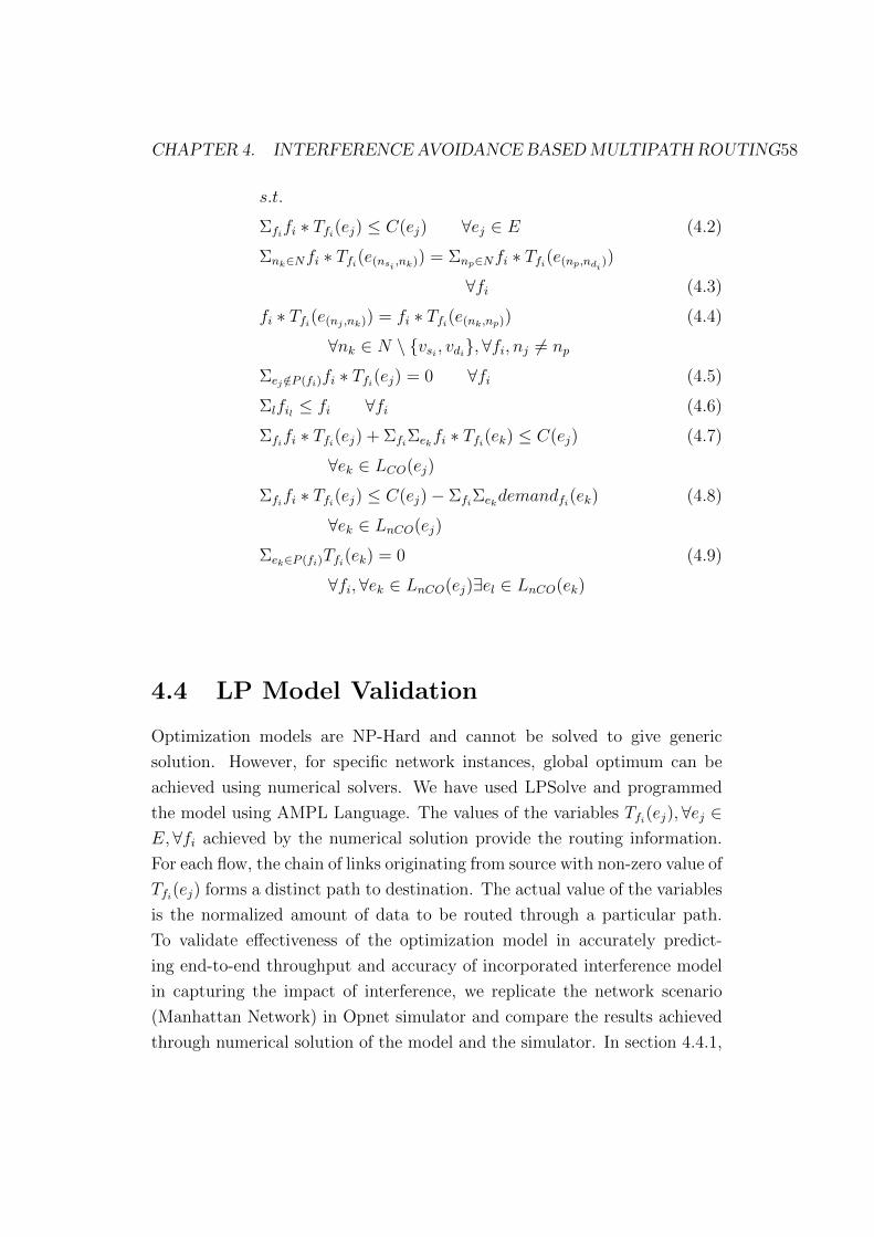
CHAPTER 4. INTERFERENCE AVOIDANCE BASEDMULTIPATH ROUTING58
s.t.
Σfifi ∗ Tfi(ej) ≤ C(ej) ∀ej ∈ E (4.2)
Σnk∈Nfi ∗ Tfi(e(nsi ,nk)) = Σnp∈Nfi ∗ Tfi(e(np,ndi))
∀fi (4.3)
fi ∗ Tfi(e(nj ,nk)) = fi ∗ Tfi(e(nk,np)) (4.4)
∀nk ∈ N \ vsi , vdi,∀fi, nj 6= np
Σej /∈P (fi)fi ∗ Tfi(ej) = 0 ∀fi (4.5)
Σlfil ≤ fi ∀fi (4.6)
Σfifi ∗ Tfi(ej) + ΣfiΣekfi ∗ Tfi(ek) ≤ C(ej) (4.7)
∀ek ∈ LCO(ej)
Σfifi ∗ Tfi(ej) ≤ C(ej)− ΣfiΣekdemandfi(ek) (4.8)
∀ek ∈ LnCO(ej)
Σek∈P (fi)Tfi(ek) = 0 (4.9)
∀fi,∀ek ∈ LnCO(ej)∃el ∈ LnCO(ek)
4.4 LP Model Validation
Optimization models are NP-Hard and cannot be solved to give generic
solution. However, for specific network instances, global optimum can be
achieved using numerical solvers. We have used LPSolve and programmed
the model using AMPL Language. The values of the variables Tfi(ej),∀ej ∈E,∀fi achieved by the numerical solution provide the routing information.
For each flow, the chain of links originating from source with non-zero value of
Tfi(ej) forms a distinct path to destination. The actual value of the variables
is the normalized amount of data to be routed through a particular path.
To validate effectiveness of the optimization model in accurately predict-
ing end-to-end throughput and accuracy of incorporated interference model
in capturing the impact of interference, we replicate the network scenario
(Manhattan Network) in Opnet simulator and compare the results achieved
through numerical solution of the model and the simulator. In section 4.4.1,

CHAPTER 4. INTERFERENCE AVOIDANCE BASEDMULTIPATH ROUTING59
Figure 4.1: Block diagram of Interferenc avoidance based Multipath routing
LP model
we have compared per flow throughput achieved using the model with that
of Opnet simulations. Section 4.4.2 evaluates the impact of variable node
density (resulting in increased coordinated interference) on average network
throughput. We have also observed the impact of constant node density
on average network throughput in section 4.4.3 which results in increase
non coordinated interference in the network. In all these experiments, the
comparison of the model and simulation results are performed to test the
effectiveness of constraints for coordinated and non-coordinated interference.
4.4.1 Comparison of Per-Flow Throughput-LPModel
vs OPNET Simulations
We use a 100 node network with nodes arranged in a 10x10 grid, such that
each node can communicate with four neighboring nodes to its left, right,
top and bottom. 40 source-destination pairs have been selected randomly.
All source nodes generate a load of 2Mbps CBR traffic, which ensures that
the network operates under saturated traffic load. Multipath routing for

CHAPTER 4. INTERFERENCE AVOIDANCE BASEDMULTIPATH ROUTING60
0
0.1
0.2
0.3
0 5 10 15 20 25 30 35 40
Thro
ug
hpu
t(M
bps)
Flow Index
LPModelOPNET
0
0.1
0.2
0.3
0 5 10 15 20 25 30 35 40
Thro
ug
hpu
t(M
bps)
Flow Index
LPModelOPNET
Figure 4.2: Comparison of per-flow throughput for Manhattan network-
LPmodel vs Opnet Simulation
Opnet is achieved by statically adding the routes that have been achieved
through solution to optimization model for the specific network instance.
Figure 4.2 compares per-flow throughput achieved using the model and the
simulations. The flows are sorted in increasing order of achieved end-to-
end throughput. The bar graph shows a good match of model results with
simulations. The average per flow throughput achieved using simulation is
≈ 89% of the average per flow throughput achieved using the model.
The second set of experiments is performed to test the effectiveness of
model for different levels of coordinated and non-coordinated interference.
This is achieved by increasing the number of nodes in the network with: (i)
constant terrain dimensions (120 x 120 m2), which results in increased coor-
dinated interference but relatively constant non-coordinated interference and
(ii) proportionately increasing terrain dimensions, which results in increased
non-coordinated interference. We have simulated the Manhattan topology
with 25, 36, 49, 64, 81 and 100 nodes.

CHAPTER 4. INTERFERENCE AVOIDANCE BASEDMULTIPATH ROUTING61
0
0.02
0.04
0.06
0.08
0.1
0.12
0.14
0.16
20 30 40 50 60 70 80 90 100 110
Nor
mal
ized
Thr
ough
put
No. of Nodes
LP ModelOPNET Simulations
0
0.02
0.04
0.06
0.08
0.1
0.12
0.14
0.16
20 30 40 50 60 70 80 90 100 110
Nor
mal
ized
Thr
ough
put
No. of Nodes
LP ModelOPNET Simulations
Figure 4.3: Impact of variable node density (Increased coordinated interfer-
ence) on average throughput
4.4.2 Comparision of Average Throughput with Vari-
able Node Density-LPModel vs OPNET
In case of constant terrain dimensions, we have generated the aggregate
traffic load of 80 Mbps from multiple sources for all scenarios. Increasing
the load beyond this value does not result in increased throughput for all
cases. Figure 4.3 compares normalized (against 80Mbps) aggregate end-to-
end throughput achieved using the model with the simulations for constant
terrain dimensions case. It is observed that the throughput slightly decreases
as the number of nodes is increased. This is because of the increased coor-
dinated interference that results in increased transmission losses. It can also
be observed that the model predicts the throughput of the network within
90% of the throughput achieved using simulations.
4.4.3 Comparison of Average Throughput with Con-
stant Node Density-LPModel vs OPNET
In case of variable terrain dimensions, we have used 9, 12, 16, 16, 20 and 24
source nodes for 25, 36, 49, 64, 81 and 100 nodes network respectively. Each
data source generates the traffic load of 2 Mbps, which results in saturated

CHAPTER 4. INTERFERENCE AVOIDANCE BASEDMULTIPATH ROUTING62
0
0.02
0.04
0.06
0.08
0.1
0.12
0.14
0.16
20 30 40 50 60 70 80 90 100 110
Nor
mal
ized
Thr
ough
put
No. of Nodes
LP ModelOPNET Simulations
0
0.02
0.04
0.06
0.08
0.1
0.12
0.14
0.16
20 30 40 50 60 70 80 90 100 110
Nor
mal
ized
Thr
ough
put
No. of Nodes
LP ModelOPNET Simulations
Figure 4.4: Impact of constant node density (variable number of nodes and
non-coordinated interference) on average flow throughput
network load for the respective topologies. For every grid size, the experiment
has been repeated 5 times with different randomly selected source-destination
pairs and the results have been averaged. It is observed that saturation point
for different sized networks is achieved at different values, unlike the variable
node density case where all sized networks are saturated with aggregate in-
put traffic load of 80 Mbps. This is because the network consists of more
carrier sensing ranges as the network size increases. The increased carrier
sensing ranges can support more traffic load. Figure 4.4 shows the normal-
ized throughput (normalized against 49 Mbps, which is saturated load for
100 nodes network) of all cases. The throughput increases with the increas-
ing network size, owing to increased number of carrier sensing ranges. The
simulations throughput is ≈ 89% of the throughput achieved using numer-
ical solution to the model. It is obvious that the accuracy of model is not
affected by increase in coordinated or non-coordinated interference. There-
fore, we conclude that model can effectively predict end-to-end throughput
for multihop wireless networks.

CHAPTER 4. INTERFERENCE AVOIDANCE BASEDMULTIPATH ROUTING63
4.5 Summary
In this chapter, we formulated joint topology control with multipath rout-
ing approach as a LP model based throughput maximization problem. The
aim of the problem formulation was to improve throughput of WMN by con-
structing multiple paths for flows after eliminating bottleneck links from the
topology which are constructed by non-coordinated interference. The prob-
lem was formulated under the assumption that the locations of the routers
are stored in a centerlized system which can be used to compute the informa-
tion of coordinated and non-coordinated interference. The model eliminated
non-coordinated interference through topology control such that the remaing
topology can be used to construct a ’quality’ paths.The objective of the model
is to maximize per-flow throughput such that available flow demand, routed
on multiple ’quality’ paths, is satisfied. The evaluation results showed that
the simulation throughput is 89% of the throughput achieved using numerical
solution which shows the effectiveness of model.

Chapter 5
Adaptive Multipath Routing
with Topology Control
5.1 Introduction
Recall from chapter 1, the redundant mesh infrastructure of WMN consists
of multiple paths between source nodes to destination nodes. The availability
of multiple paths offer several advantages which include fault tolerance and
load balancing. In view of these advantages, a number of multipath rout-
ing algorithms exist such as Ad-Hoc On Demand Multipath Distance Vector
(AOMDV) [10] and Multipath Dynamic Source Routing (MDSR) [123] which
aims at improving end-to-end throughput of the flows by simultaneously
transmitting them on several paths. Despite these advantages, the highly
connected network topology, offering multiple paths to flows, induces signif-
icant interference which reduces the overall network performance. Thus in
order to achieve better performance using multipath routing, it is important
to eliminate the impact of this inbuilt interference using topology control.
In this chapter, we propose a centralized topology control and greedy
heuristic multipath routing scheme that can be used to compute quality paths
in a given network configuration while trying to maximize the aggregate end-
to-end throughput. Based upon the optimization model proposed in chapter
4, high quality paths for all flows are computed. Adaptive multipath routing
scheme with topology control (AMRTC) constructs paths in two phases.
64

CHAPTER 5. ADAPTIVEMULTIPATH ROUTINGWITH TOPOLOGY CONTROL65
In the first phase, multilevel interference dependencies are identified which
result in the creation and identification of bottleneck links in the physical
topology. The topology control algorithm is used to eliminate the effects
of non-coordinated interference by purging those links which are imposing
severe interference on other links. In the second phase, AMRTC selects the
subset of quality links from the resultant topology and creates paths for the
flows.
The chapter is organized as follows. In Section 5.2, we present the adap-
tive multipath routing scheme AMRTC. The topology control and multipath
routing algorithms of AMRTC are presented in sections 5.2.1 and 5.2.2
respectively. Section 5.3 presents the path construction comparison of LP
model and AMRTC. The evaluation of AMRTC is performed in section 5.4
and finally section 5.5 concludes the chapter.
5.2 AMRTC - Adaptive Multipath Routing
with Topology Control
We present an adaptive multipath routing scheme which incorporates topol-
ogy control (AMRTC). AMRTC is a centralized scheme which executes in
two phase. In the first phase, AMRTC performs topology control to identify
and prune the multilevel non-coordinated interfering links. As discussed in
chapter 3, due to the asymmetric channel view, the multilevel effects of non-
coordinated interference are propagated to the links on several hops away.
Thus AMRTC estimates these effects and avoids those links which are un-
der severe interference and creating bottleneck for the path. The resultant
topology control graph is used in the second phase where maximum available
residual capacity paths to satisfy the flow demands are selected. Extensive
simulation-based evaluation is carried out to study the effectiveness of the
proposed scheme. The results show that AMRTC can effectively avoid the
impact of coordinated as well as non-coordinated interference and can achieve
good performance under different scenarios.

CHAPTER 5. ADAPTIVEMULTIPATH ROUTINGWITH TOPOLOGY CONTROL66
5.2.1 AMRTC-Topology Control Algorithm
The scheme first performs topology control on the network. The links creat-
ing chain dependencies and having low channel utilization are purged from
the network topology. Algorithm 1 is used for this purpose. Given the set
of nodes and edges and the distance between all nodes, step 1 to step 6 of
the algorithm identify non-coordinated interfering links of each link in set E.
Step 7 to step 29 are used to purge the links that have limited throughput
because of non-coordinated interference. On step 19, the link that experi-
ences non-coordinated interference from any of the links that themselves do
not experience non-coordinated interference, are removed from the set Et of
links. Removal of such links results in fewer paths for all flows; however,
the forwarding capacity of remaining links will reduce negligibly (if at all).
Step 23 adds to set X the links that experience non-coordinated interference
from the link that is to be purged from topology. Effectively, all links in
set X should experience no non-coordinated interference. Finally, step 30
to step 37 are used to compute the sets of coordinated and non-coordinated
links for each link in the network topology (Set Et) after topology control.
5.2.2 AMRTC-Multipath Routing Algorithm
Topology control is followed by greedy heuristic based multipath routing al-
gorithm. Algorithm 2 constructs one path at a time for each flow using
Dijkstra algorithm [126]. The cost of using each link for Dijkstra algorithm
is the inverse of the link capacity. Initially the link capacity of all links
is set to maximum. After every path construction and percentage of flow
assignment on that path, the link capacity is updated by subtracting the
aggregate data being forwarded by the link and its coordinated interfering
links. The process is repeated until predefined maximum number of paths is
constructed for each flow. Note that first path constructed for each flow will
be maximum capacity path. In each path iteration, the forwarding capacity
of each subsequent path will be lesser than the path constructed threshold
percentage of each flow is routed. AMRTC is a centralized algorithm and
can be executed on any of the gateway nodes. The coordinates information
is available with each deployed node. Flows in WMN are not known a priori.

CHAPTER 5. ADAPTIVEMULTIPATH ROUTINGWITH TOPOLOGY CONTROL67
Algorithm 1 Topology Control Algorithm
Require: N,E, d(ni, nj)∀ni, nj ∈ NEnsure: Et ⊂ E,LCO(ei), LnCO(ei)∀ei ∈ Et
1: for ei ∈ E do
2: LnCO(ei)⇐ φ
3: for ej ∈ E do
4: LnCO(ei)⇐ non-co Info. Asy. links of ei
5: end for
6: end for
7: Et ⇐ E
8: E ′ ⇐ E
9: X ⇐ φ
10: for ei ∈ E ′ do
11: if LnCO(ei) = φ then
12: X ⇐ X ∪ ei . Links with no nCO interference
13: end if
14: end for
15: E ′ ⇐ E ′ \X16: while E ′ 6= φ do . Find and purge low TP links forming nCO Chains
17: for ei ∈ E ′ do
18: if LnCO(ei) ∩X 6= φ then
19: Et ⇐ Et \ ei . Link with nCO, Low TP
20: E ′ ⇐ E ′ \ ei21: for ej ∈ E ′ do
22: if LnCO(ej) ∩ ei 6= φ then
23: X ⇐ X ∪ ej . Link with nCO, high TP
24: E ′ ⇐ E ′ \ ei25: end if
26: end for
27: end if
28: end for
29: end while
30: for ei ∈ Et do . Compute CO and nCO sets for all links in Topology
31: LCO(ei)⇐ φ
32: LnCO(ei)⇐ φ

CHAPTER 5. ADAPTIVEMULTIPATH ROUTINGWITH TOPOLOGY CONTROL68
33: for ej ∈ Et do
34: LnCO(ei)⇐ non-co Info. Asy. links of ei
35: LCO(ei)⇐ co links of ei
36: end for
37: end for
For this purpose, the weighted running average of the average data trans-
mitted in previous interval and the MAC layer packet queue can be used.
Higher weight may be assigned to average transmitted data to reduce the
bursty nature of flows. The information of coordinates of nodes and the flow
demands can be periodically transmitted to the designated gateway through
specifically designed protocol messages and pre-configured control messages
only routes from nodes to the designated gateway. Any update in routing
information can be communicated back to the nodes. Therefore, AMRTC
can easily be transformed into a practically implementable centralized rout-
ing protocol. Figure 5.1(a) represent the flow of AMRTC Topology Control
algorithm and 5.1(b) represents the flow of AMRTC Multipath Routing al-
gorithm.
5.3 Path Construction Comparison of LP Model
and AMRTC
Figure 5.3 represents the path construction comparison of LP Model and
proposed AMRTC algorithm. Figure 5.2(a) shows original network topol-
ogy which has been fed into LP model and AMRTC. LP model takes this
network as input and constructs flow paths (figure 5.2(b)) based on the im-
posed constraints to achieve maximized end-to-end throughput. As shown
in the topology, model removes low quality links and uses remaining links
to construct flow paths to achieve maximized throughput. Now consider
Figure 5.3(a) representing the working of AMRTC algorithm; start with
dotted arrow headed link (1,2) which is under non-Co interference of solid
arrow headed links (10,9) and (16,9). Working out the Topology Control
phase of AMRTC Algorithm, all such non-CO interfering links are identified.

CHAPTER 5. ADAPTIVEMULTIPATH ROUTINGWITH TOPOLOGY CONTROL69
(a) Flow chart of AMRTC Toplogy Control algorithm
(b) Flow chart of AMRTC Multipath Routing algorithm
Figure 5.1: Flow chart of AMRTC algorithm

CHAPTER 5. ADAPTIVEMULTIPATH ROUTINGWITH TOPOLOGY CONTROL70
(a) Original Topology fed into LP Model and AMRTC Algorithm
(b) Topology created after LP Model execution
Figure 5.2: LP Model path construction

CHAPTER 5. ADAPTIVEMULTIPATH ROUTINGWITH TOPOLOGY CONTROL71
(a) Topology created with AMRTC initial run
(b) Final Topology created after AMRTC complete execution
Figure 5.3: AMRTC path construction

CHAPTER 5. ADAPTIVEMULTIPATH ROUTINGWITH TOPOLOGY CONTROL72
Algorithm 2 Multipath Routing Algorithm
Require: Et, N, C(ei), NumberPaths,D(fsd) or D(fi) (max achievable flow
rate between ns and nd) ∀ns, nd ∈ NEnsure: P (fi)∀fi set of paths
1: for NumberPaths do
2: for all fi do
3: if D(fi) > 0 then
4: p⇐ Dijkstra(Et, N, C(ei)ns, nd)
5: D(fi)⇐ maxD(fi)−min(links(p)), 06: P (fi)⇐ P (fi) ∪ p7: for ei ∈ Et do
8: Update C(ei)
9: end for
10: end if
11: end for
12: end for
Then set X is initialized (step 12) with those links which do not experience
any non-co interference from any other link; which in this case is initially
empty. The steps 16 to 29 of algorithm 1, executes a loop on the edges to
identify and remove the chains of non-Co interference. As link (1,2) is on
the edge of topology and does not form any chain of interference on other
links, thus it is added to set Et whereas links (10,9) and (16,9) are added
to set X to further evaluate the interfering impact of other links on them.
Now consider link (3,10) which is under non-Co interference of links (8,9)
and (12,13) and forms a chain of non-CO interference on link (16,9). Thus
link (3,10) is removed from the topology to break the interfering chain and
links (8,9) and (12,13) is added to set X. Continuing with this loop, all those
links are eliminated from the topology which forms interfering chains. The
remaining links, stored in set Et and X, experience little or no non-CO in-
terference. Now this interference controlled topology has been fed into the
second phase of AMRTC which uses dijkstra algorithm to construct paths.
Figure 5.3(b) represents the paths formed after complete execution of AM-
RTC algorithm. Compared to LP model, AMRTC construct lesser paths for

CHAPTER 5. ADAPTIVEMULTIPATH ROUTINGWITH TOPOLOGY CONTROL73
flows but considerably removes non-CO interfering chains to achieve better
end-to-end throughput.
5.4 Performance Evaluations
This section presents the simulation-based evaluation of the proposed algo-
rithm. We have compared the performance of proposed multipath scheme
AMRTC with the following three algorithms: (i) Ad-Hoc On Demand Multi-
path Distance Vector (AOMDV) [10] (ii) Multipath Dynamic Source Routing
(MDSR) [123] and (iii) AVAIL [124]. Results from optimization model are
also compared in all experiments. AOMDV, the multipath variant of well-
known AODV, is a distance-vector routing algorithm which constructs loop
free, disjoint alternate paths in multihop networks. Similarly, MDSR is the
multipath extension of DSR which uses IP source routing to construct link-
wise disjoint paths from source to destination. AVAIL is a unipath routing
scheme. The scheme is a modified version of Dijkstras algorithm and discov-
ers comparatively high throughput longer path for each flow whilst consider-
ing interference on links. The comparison demonstrates the effectiveness of
proposed AMRTC algorithm which prioritizes quality of paths by ignoring
links under severe multilevel interference.
5.4.1 Experimental Setup
To evaluate the performance of the proposed algorithm, we have used Man-
hattan network topology [124]. In Manhattan network, the nodes are ar-
ranged in a symmetric grid such that each node is within transmission range
of only its North, South, East, and West neighbors. The carrier sensing
range of the nodes is set to 1.8 times the transmission range so that a node
can sense the activity of all of its eight direct neighboring nodes. A set of
nodes is randomly selected as source nodes to generate a load of 2Mbps each.
To achieve this load, each source generates a packet of 512 bytes after ev-
ery 2 mSec. Similarly, another set of nodes is randomly selected as gateway
nodes to act as destinations for the source nodes. Exact number of nodes
selected varies in different experiments and is mentioned with experiment.

CHAPTER 5. ADAPTIVEMULTIPATH ROUTINGWITH TOPOLOGY CONTROL74
Table 5.1: Simulation Parameters for AMRTC experiments
Simulation time 1200 sec.
Terrain Dimensions 500× 500m2
Node Placement Regular Grid (Manhat-
tan Network)
Radio interface type IEEE 802.11b
Radio propagation model Two ray
Propagation shadowing model Constant (mean=4.0)
Application Traffic CBR
Packet Inter-arrival Time 2 mSec
Packet Size 512 Bytes
IEEE 802.11b radios are used for simulations. Table 5.1 summarizes the
simulation parameters used in all experiments unless otherwise stated. The
evaluation is performed through four sets of experiments. In first set, we
show the effectiveness of multipath routing over unipath routing. In the sec-
ond set, the performance of AMRTC is compared with AOMDV, MDSR and
AVAIL in terms of offered traffic load and network throughput. The third
set of experiments is conducted to compare the performance of the four al-
gorithms with respect to quantity and length of the selected paths. Last set
compares the average per-flow throughput achieved when number of nodes is
increased with constant and variable node density. This tests the algorithms
under varying level of coordinated and non-coordinated interference.
5.4.2 Unipath Vs. Multipath Routing
In this set of experiments, we have considered 100-nodes Manhattan net-
work arranged in a 10x10 regular grid. Among these nodes, 9 nodes are
randomly selected as gateway nodes while 40 source nodes are randomly
selected to generate traffic towards its nearest gateway. Traffic load of the
source nodes is increased from 25 pkts/sec (packet transmitted every 40mSec)
to 1500 pkts/sec (packet transmitted every 0.6mSec). Figure 5.4(a) plots the

CHAPTER 5. ADAPTIVEMULTIPATH ROUTINGWITH TOPOLOGY CONTROL75
0
1
2
3
4
5
6
0 200 400 600 800 1000 1200 1400 1600
Net
wor
k T
hrou
ghpu
t (M
bps)
Traffic Load (Pkts/sec)
LP Model (Multipath)AMRTC
LP Model (Single Path)AODV
0
1
2
3
4
5
6
0 200 400 600 800 1000 1200 1400 1600
Net
wor
k T
hrou
ghpu
t (M
bps)
Traffic Load (Pkts/sec)
LP Model (Multipath)AMRTC
LP Model (Single Path)AODV
(a) Comparison of multiple path and single
path routing
0
1
2
3
4
5
6
0 200 400 600 800 1000 1200 1400 1600
Net
wor
k T
hrou
ghpu
t (M
bps)
Traffic Load (Pkts/sec)
LP ModelAMRTCAOMDV
MDSRAVAIL
0
1
2
3
4
5
6
0 200 400 600 800 1000 1200 1400 1600
Net
wor
k T
hrou
ghpu
t (M
bps)
Traffic Load (Pkts/sec)
LP ModelAMRTCAOMDV
MDSRAVAIL
(b) Impact of increasing traffic load on
throughput
0
0.05
0.1
0.15
0.2
0.25
0.3
0 5 10 15 20 25 30 35 40
Thr
ough
put (
Mbp
s)
Flow Index
LP ModelAMRTCAOMDV
MDSRAVAIL
0
0.05
0.1
0.15
0.2
0.25
0.3
0 5 10 15 20 25 30 35 40
Thr
ough
put (
Mbp
s)
Flow Index
LP ModelAMRTCAOMDV
MDSRAVAIL
(c) Per flow throughput comparison of the
four algorithms for Manhattan network
0
5
10
15
20
25
30
35
40
0 1 2 3 4 5
Flo
w In
dex
No. of Hops/Path
LP ModelAMRTCAOMDV
MDSRAVAIL
0
5
10
15
20
25
30
35
40
0 1 2 3 4 5
Flo
w In
dex
No. of Hops/Path
LP ModelAMRTCAOMDV
MDSRAVAIL
(d) Average path length comparison
0
1
2
3
4
5
0 5 10 15 20 25 30 35 40
No.
of P
aths
Flow Index
LP ModelAMRTCAOMDV
MDSRAVAIL
0
1
2
3
4
5
0 5 10 15 20 25 30 35 40
No.
of P
aths
Flow Index
LP ModelAMRTCAOMDV
MDSRAVAIL
(e) Number of paths comparison
0
1
2
3
4
5
6
20 30 40 50 60 70 80 90 100 110
Avg
. Thr
ough
put(
Mbp
s)
No. of Nodes
AMRTCAOMDV
MDSRAVAIL
0
1
2
3
4
5
6
20 30 40 50 60 70 80 90 100 110
Avg
. Thr
ough
put(
Mbp
s)
No. of Nodes
AMRTCAOMDV
MDSRAVAIL
(f) Impact of node density on throughput
Figure 5.4: Performance Evaluation of AMRTC

CHAPTER 5. ADAPTIVEMULTIPATH ROUTINGWITH TOPOLOGY CONTROL76
aggregate end-to-end throughput achieved using optimization model (multi-
path), AMRTC, optimization model (unipath) and AODV (shortest path)
algorithms. Results have been averaged over 5 simulation runs. It can be
observed that for network load (≈ 800 pkts/sec), performance of Unipath
and multipath optimization model is same. However, as the offered traffic
load increases, multipath optimization model marginally outperforms uni-
path optimization model. The saturated traffic load that is routed by mul-
tipath routing based optimization model is 3.21 Mbps while that of unipath
routing based optimization model is 3.062 Mbps. The reason that multipath
routing based optimization model can only marginally outperform the uni-
path routing based optimization model is attributed to the fact that even
single path optimization model is able to eliminate non-coordinated inter-
fering links. This reduces the possibility of significant number of alternate
paths for the flows. On the other hand, AMRTC (saturated throughput 1.61
Mbps), which is multipath routing algorithm, outperforms AODV (saturated
throughput 1.23 Mbps) under saturated traffic load. It can be concluded that
multipath routing shall be used under all scenarios of saturated as well as
unsaturated traffic load. It can also be observed that appropriately address-
ing the non-coordinated interference while deciding upon the routes results
in good performance, even for unipath routing, which is the case for results
from unipath optimization model.
5.4.3 Offered Traffic Load and End-to-End Through-
put
Next we compare the performance of different multipath routing algorithms.
The experimental setup is same as in previous section with 100 nodes ar-
ranged in grid within terrain dimensions of 120 x 120 m2. This arrangement
of nodes results in 12 neighbouring nodes within the transmission range of
each node and results in dense deployment of nodes. Figure 5.4(b) plots the
impact of increasing traffic load on aggregate end-to-end throughput when
the traffic load is gradually increased from below saturation (i.e. 25pkt/sec
to 100pkt/sec) point to above saturation (i.e. 200pkts/sec to 1500pkt/sec).
It is evident that AMRTC outperforms the other three schemes by achiev-
CHAPTER 5. ADAPTIVEMULTIPATH ROUTINGWITH TOPOLOGY CONTROL77
ing a higher saturated aggregate end-to-end throughput with a factor of 1.37,
1.68 and 1.63 with respect to AVAIL, AOMDV and MDSR respectively. This
increase is the result of avoiding badly suffered links due to non-coordinated
interference during path selection procedure. AMRTC outperforms AVAIL
because it explicitly avoids bottleneck links as well as chain interference de-
pendencies by purging the responsible links. AVAIL is unable to avoid the
chain interference dependencies because it selects longer paths. Also note
that AVAIL outperforms MDSR and AOMDV because it tries to select qual-
ity paths instead of selecting shortest paths. Therefore, chances of avoiding
the bottleneck links increases in case of AVAIL.
Fairness
Although AMRTC achieves higher aggregate end-to-end throughput com-
pared to AVAIL, AOMDV and MDSR, it is important for good performance
of routing algorithm to provide some notion of fairness among the input
flows. To evaluate the fairness, we have computed Jain’s fairness index [127]
for the 40 flows of 100 nodes topology. Jain’s fairness index for flows using
AMRTC, AVAIL, AOMDV and MDSR is 0.49, 0.73, 0.73 and 0.74 respec-
tively. This means that AMRTC is less fair when it comes to throughput
distribution among flows compared to AVAIL, AOMDV and MDSR that are
equally fair. This can also be observed in Figure 5.4(c) where throughput
achieved by individual flows have been plotted. It can be seen that no path
has been selected for 19 flows (out of 40) by AMRTC. To introduce fairness,
we first turn to the optimization model and introduce fairness constraints in
the model. We have considered following four constraints.
Proportional Fair Share: Every flow gets a proportion of its demand (capped
by link capacity to avoid excessively large flows) fulfilled. The proportion
fulfilled for all flows is within the fairness threshold (FairTH) of each other.
This can be achieved using following constraint.
|Σnk∈NTfi(e(nsi ,nk))−Σnp∈NTfj(e(nsj ,np))| ≤ FairTH ∀fi, fj
This constraint results in infeasible model for the 40 flow example, even for
large values of FairTH . This means that for the given topology, achieving

CHAPTER 5. ADAPTIVEMULTIPATH ROUTINGWITH TOPOLOGY CONTROL78
this type of fairness is not possible. This is because of the excessive traffic
load compared to the capacity of the network. Furthermore, certain flows
have no feasible path that can route the amount of traffic requested.
Fair Share: The demand fulfilled for all flows is within the fairness threshold
of other flows. The constraint is given by following expression.
|Σnk∈Nfi ∗ Tfi(e(nsi ,nk))−Σnp∈Nfj ∗ Tfj(e(nsj ,np))| ≤ FairTH ∀fi, fj
This is more strict constraint and results in infeasible model even for much
smaller topologies.
Minimum Demand Served: This constraint ensures that for every flow, at
least a minimum quantity of the flow demand is fulfilled. The constraint is
given as:
Σnk∈Nfi ∗ Tfi(e(nsi ,nk)) ≥ dmin ∀fi
This constraint can be replaced by max-min objective where minimum de-
mand fullfilled for any flow is maximized. It is easy to show that even for
simple topology and two flows with one flow having a link that experiences in-
formation asymmetric interference, even the minimal value of dmin = 128kbps
leads to infeasible solution. This is also evident from Figure 5.4(c) where upto
12 flows in all algorithms receive throughput lower than 128 kbps. Given the
fact that data is aggregated for multiple end users at each router, the lim-
ited throughput of 128 kbps may not fulfil requirements of any application.
Consequently, the assigned capacity is wasted.
Maximum Data Limit: This constraint ensures that no flow can get the
throughput more than the upper limit on demand served. The constraint is
given as:
Σnk∈Nfi ∗ Tfi(e(nsi ,nk)) ≤ dmax ∀fi
This constraint produces better results compared to the above considered
constraints. The results are shown in Figure 5.5 where 48 flows have been
considered and the dmax is set to 1 Mbps. It can be seen that 18 flows get
throughput of 1 Mbps. Note however, that a number of flows still starve

CHAPTER 5. ADAPTIVEMULTIPATH ROUTINGWITH TOPOLOGY CONTROL79
with no path constructed for them. Same constraint has been tested for
AMRTC by limiting the flow demand and the results are shown in same
Figure. Three facts are worth considering that does not support the use of
such a constraint in practice. First of all, limiting the maximum throughput
actually results in unfair treatment of the routers that support more num-
ber of users (or fewer users with higher demand), compared to the routers
that support fewer users. Secondly, it is not easy to implement the policy
of limiting the data of a node, specifically in case of infrastructure WMN
where every node is aggregation point for multiple end user devices as well
as forwarding node for other flows. In such situation, it is not possible to
distinguish the traffic generated from router and the traffic being forwarded
for other flows. This is because all data packets have the source IP that is
not same as the router itself. Finally, limiting the maximum demand ful-
filled for flows still does not guarantee that other flows will not starve. At
the same time, aggregate capacity is not increased for the network. From
above discussion, it can safely be concluded that introducing the notion of
fairness into the routing algorithm does not produce desired results, unless
admission control algorithm is employed to limit the number of flows and the
demand of each flow. Even in presence of such measures, true fairness might
not be achievable. Therefore, the presented algorithm does not attempt on
incorporating fairness.
5.4.4 Length and Number of Paths
With experimental set of above sections, we first compare the length of the
paths selected by the four algorithms. Subsequently, we compare the av-
erage number of paths created by each algorithm. Figure 5.4(d) plots the
path length against the number of flows having the specified path length
for the four algorithms. AMRTC selects paths with average path length of
2.09. This shows that although purging a subset of links from the network
results in no connectivity for certain flows, it does not significantly affect the
path length for remaining flows. Longest paths are selected by AVAIL with
average path length of 2.48. This is because AVAIL tries to construct longer
paths with higher link diversity and improved path quality. More number of

CHAPTER 5. ADAPTIVEMULTIPATH ROUTINGWITH TOPOLOGY CONTROL80
0
0.2
0.4
0.6
0.8
1
1.2
1.4
1.6
1.8
2
0 5 10 15 20 25 30 35 40 45
Thro
ughp
ut (M
bps)
Flow Index
LP ModelAMRTC
0
0.2
0.4
0.6
0.8
1
1.2
1.4
1.6
1.8
2
0 5 10 15 20 25 30 35 40 45
Thro
ughp
ut (M
bps)
Flow Index
LP ModelAMRTC
Figure 5.5: Fairness Constraint Impact
hops per path result in relatively lesser end-to-end throughput for AVAIL,
compared to AMRTC. Average path length of MDSR and AOMDV is 2.1
and 2.25 respectively. This is because both algorithms are shortest path algo-
rithms and do not take quality of links into account while constructing paths.
Smaller value of average path length for AOMDV and MDSR confirms that
link diversity is not achieved using both algorithms, consequently leading to
lower end-to-end throughput. Figure 5.4(e) shows the number of paths cre-
ated for each flow using four algorithms. Maximum number of paths for any
flow constructed by four algorithms is 2 except AVAIL, which is a unipath
algorithm with maximum number of paths to be 1 for all flows. Average
number of paths constructed by AMRTC, AOMDV and MDSR are 1.71,
1.42 and 1.5 respectively. AMRTC constructs fewer paths because purging
of a subset of links from the network reduces the possibility of constructing
multiple paths that can also result in capacity improvement. This justifies
the limited improvement of multipath optimization model compared to uni-
path optimization model in Figure 5.4(a). Note that AVAIL being a unipath
algorithm and selecting high throughput links for each path shall have lesser
interference on all links and should have achieved better end-to-end through-
put; however, this is not the case. Relatively lesser throughput for AVAIL,

CHAPTER 5. ADAPTIVEMULTIPATH ROUTINGWITH TOPOLOGY CONTROL81
compared to AMRTC is attributed to the fact that the constructed paths
are longer (as shown through Figure 5.4(d)). It is known that end-to-end
throughput exponentially decreases with increasing path length. Also note
that AMRTC has constructed more paths compared to AOMDV and MDSR;
however, AMRTC has outperformed MDSR and AOMDV because the se-
lected paths have link diversity as well as low interference links, resulting in
high quality paths. Consequently, AMRTC leads to improved end-to-end ag-
gregate throughput because it achieves both objectives of constructing fewer
paths and paths with higher quality links.
5.4.5 End-to-end Delay
End-to-end delay is another important factor for deciding the effectiveness
of the routing algorithm. Figure 5.6 shows end-to-end delay for 100 nodes
network with 40 end to end flows. The average per flow end-to-end delay
for AMRTC (0.0437) is significantly lower, compared to AOMDV (0.0556),
MDSR (0.0742) and AVAIL (0.0899). This clearly shows the advantage of
selecting quality paths. With the paths having lesser collision probability,
the number of unsuccessful transmissions is negligible. With lesser number
of collisions, the time wasted because of increased backoff window as well as
the time wasted because of retransmission of packets is avoided. Therefore,
minimal delay is experienced at each hop, resulting in lesser end to end delay
for almost all flows.
5.4.6 Impact of Increasing Node Density
Final set of experiments have been conducted to observe the impact of in-
creasing number of nodes on average throughput using AMRTC, AVAIL,
AOMDV and MDSR. We have simulated and observed the performance of
the four algorithms over 25, 36, 49, 64, 81, and 100 nodes network where
nodes are arranged in a regular grid. Increasing the nodes keeping the ter-
rain dimensions constant; results in rapid increase in number of coordinated
interfering links and relatively slower increase in number of non-coordinated
interfering links. On the other hand, increasing the number of nodes while
keeping the node density constant (by proportionally increasing terrain di-

CHAPTER 5. ADAPTIVEMULTIPATH ROUTINGWITH TOPOLOGY CONTROL82
0
0.1
0.2
0.3
0.4
0.5
0.6
0 5 10 15 20 25 30 35 40
Avg
. End
-to-
End
Del
ay (
sec)
Flow Index
AMRTCAOMDV
MDSRAVAIL
0
0.1
0.2
0.3
0.4
0.5
0.6
0 5 10 15 20 25 30 35 40
Avg
. End
-to-
End
Del
ay (
sec)
Flow Index
AMRTCAOMDV
MDSRAVAIL
Figure 5.6: End-to-end Delay
mensions) results in rapid increase of non-coordinated interference while coor-
dinated interference remains almost constant. For example, 49 nodes network
arranged in a terrain area of 120 x 120 m2 results in 127 coordinated and
127 non-coordinated interference links. For 100 nodes (doubling the nodes)
arranged in same terrain area results in 203 (two-fold increase) coordinated
and 159 non-coordinated links. On the other hand, 100 nodes arranged
in 270 x 270 m2 terrain area results in 203 coordinated and 203 (two-fold
increase) non-coordinated links. We present the results with increasing num-
ber of nodes and same terrain dimensions (Variable node density) as well
as proportionally increased terrain dimensions (Uniform node density). Fig-
ure 5.4(f) shows aggregate end-to-end throughput for the four algorithms for
different number of nodes deployed within constant terrain dimensions of 120
x 120 m2. This results in increased node density with the increase in num-
ber of nodes (i.e. variable node density) and leads to increased coordinated
interference. It can be seen that AMRTC consistently outperforms AVAIL,
AOMDV and MDSR for all number of nodes. Also note that as node density
is increased, the achievable aggregate end-to-end throughput by AMRTC
slightly decreases. This is because of increased coordinated interference that
results in minor increase in transmission losses among interfering links. The

CHAPTER 5. ADAPTIVEMULTIPATH ROUTINGWITH TOPOLOGY CONTROL83
0
1
2
3
4
5
6
20 30 40 50 60 70 80 90 100 110
Avg
. Thr
ough
put(
Mbp
s)
No. of Nodes
AMRTCAOMDV
MDSRAVAIL
0
1
2
3
4
5
6
20 30 40 50 60 70 80 90 100 110
Avg
. Thr
ough
put(
Mbp
s)
No. of Nodes
AMRTCAOMDV
MDSRAVAIL
Figure 5.7: Impact of increasing no. of nodes (with constant node density)
on average throughput
trend also suggests the creating more paths will further increase the interfer-
ence and may not necessarily result in improved forwarding capacity. AVAIL
is able to perform slightly better compared to AOMDV and MDSR because
of link diversity. Figure 5.7 shows the impact of increasing nodes with con-
stant node density on average throughput achieved using AMRTC, AVAIL,
AOMDV and MDSR. It can be observed that AMRTC achieves significantly
better throughput compared to rest of the algorithms. The improved perfor-
mance is because of adequate handling of non-coordinated interference. It
can also be observed that although AVAIL avoids poor quality links, with
the increase in terrain dimensions and non-coordinated interference, signifi-
cant number of links experience non-coordinated interference. AVAIL avoids
all such links, resulting in longer paths, which results in reduced end-to-end
throughput. AOMDV and MDSR achieve lesser throughput because these
algorithms construct shortest paths and do not avoid bottleneck links during
route selection.

CHAPTER 5. ADAPTIVEMULTIPATH ROUTINGWITH TOPOLOGY CONTROL84
5.5 Summary
The chapter presented an adaptive algorithm of multipath routing and topol-
ogy control for quality route selection to achieve the objective of interference
avoidance based multipath routing model (LP model). Topology control was
used to eliminate non-coordinated interference dependencies which resulted
in fewer paths, each having fewer hops. This phase of link purging improved
the quality of the remaining paths. Thus AMRTC selected these maximum
available residual capacity paths to satisfy the flow demand which resulted
in improved end-to-end throughput. Extensive simulation-based evaluation
showed that AMRTC outperformed the existing schemes by achieving a
higher saturated aggregate end-to-end throughput with a factor of 1.37, 1.68
and 1.63 with respect to AVAIL, AOMDV and MDSR respectively.. Com-
pared to existing multipath routing algorithms as well as unipath routing
algorithms that aim at constructing high quality routes, AMRTC effectively
mitigated the impact of coordinated as well as non-coordinated interference
and achieved good performance under different scenarios.

Chapter 6
Interference Mitigation based
Multipath Routing
6.1 Introduction
The interference avoidance based multipath routing model presented in chap-
ter 4 eliminates multi-level interference dependencies by avoiding links under
severe interference during route selection. The interfering link avoidance
through topology control is aimed to reduce the multi-level impact of inter-
ference on overall end-to-end throughput. This elimination results in fewer
paths with fewer hops and results in unfair distribution of flow demand. In
this chapter, we have dealt with the multi-level impact of non-coordinated
interference through capacity adjustment of interfering links.
We formulate the throughput maximization problem as a Mixed Integer
Nonlinear Programming (MINLP) model. The model takes traffic load and
interference dependencies as an input with an objective to maximize end-to-
end throughput. The problem formulation ensures that the capacity of links
experiencing non-coordinated interference is carefully adjusted such that the
bottleneck links, created due to multi-level interference, are removed. The
model also ensures the fair distribution of traffic load among links. The
solution to the optimization model gives an upper bound on the optimal
throughput of the network.
The rest of the chapter is organized as follows: Section 6.2formulates the
85

CHAPTER 6. INTERFERENCEMITIGATION BASEDMULTIPATH ROUTING86
problem and describes the assumptions and notations used. In section 6.3,
we develop interference mitigation based multipath routing as MINLP model
and present its decision variables, constraints set and objective function.
Section 6.4 validates the effectiveness of the model by comparing its numerical
solution with simulations. The network scenarios which are used to execute
MINLP model are reproduced in opnet simulator to compare the results with
numerical solution with that of simulation. In section 6.5, we evaluate the
performance gain of MINLP model and its simulations with recent existing
approaches. Finally, section 6.6 concludes the chapter.
6.2 Interference Mitigation based Multipath
Routing – Problem Formulation
This section presents an optimization framework of throughput maximization
problem which extends the interference avoidance model presented in chapter
4. The model incorporates coordinated and non-coordinated interference
constraints to mitigate inbuilt multi-level interference dependencies through
link capacity adjustments. It computes upper bound on optimal throughput
of a network with given traffic load. We begin with network and interference
model describing notations and terminologies.
6.2.1 Network and Interference Model
The network model used in this problem is extended from chapter 4. The
directed graph G(N,E), with N being set of mesh nodes and E ∈ N × Nbeing set of links, represent WMN. Let d(ni, nj) represent the distance be-
tween (ni, nj). An edge e(ni, nj) ∈ E exists between ni and nj if dij ≤ Rtr.
Maximum data capacity of link ej is given by Cej∀ej ∈ E. Let fi represent
the data demand of ith end-to-end flow in the network. Each flow may be
routed through multiple sub-flows using multipath routing. Let fil repre-
sent a sub-flow of flow fi. Let eh(ni, nj) denote a directed link between ni
and nj, where ni represents transmitter and nj represents receiver, then a
directed link e′h(n′i, n′j) is an interfering link if d(ni, n′j), d(ni, n′i), d(nj, n′j)

CHAPTER 6. INTERFERENCEMITIGATION BASEDMULTIPATH ROUTING87
Table 6.1: List of Notations for MINLP model
N Set of vertices/nodes
E Set of directed links
G Directed network topology graph
effCapek Effective Capacity of link ek ∈ EadjCapek Adjusted Capacity of link ek ∈ Efi(ns− > nd) Flow between nodes ns, nd
P (fi) Set of all links on path for flow fi
LCO(ej) Set of coordinated links of ej
LnCO(ej) Set of non-coordinated links of ej
or d(nj, n′i) ≤ RCS. Two links eh(ni, nj) and e′h(n′i, n′j) are observing co-
ordinated interference if d(ni, n′i) ≤ RCS i.e. if the transmitters of the links
are within the carrier sensing range of each other. On the contrary, two links
eh(ni, nj) and e′h(n′i, n′j) are said to be non-coordinated interfering links
if d(ni, n′i) > RCS and d(ni, n′j) ≥ RCS, and/or d(n′i, nj) ≥ RCS, and/or
d(nj, n′j) ≥ RCS. The notations used in optimization model are listed in
Table 6.1.
6.3 MINLP Program Formulation
We now formulate the interference mitigation based multipath routing prob-
lem in multihop WMN. The objective of the optimization problem is to
maximize the end-to-end throughput of the network while ensuring non-
coordinated interference elimination and fair distribution of throughput among
flows. The following sections define the constraint set and decision variables
and next state the objective function.
6.3.1 Decision Variables
The optimization model computes the normalized data flow of fi through
link ej. This is represented by two decision variables Tfi(ej) and Pfi(ej) as

CHAPTER 6. INTERFERENCEMITIGATION BASEDMULTIPATH ROUTING88
described below.
Tfi(ej) is represented by a binary variable where the value of 1 indicates
that a flow fi is routed from a link ej.
Tfi(ej) =
1, if link ej carries data for flow fi
0, otherwise
Pfi(ej) represents the fraction of flow on a link where the value of 0 for a
given flow-link pair indicates that the link is not on path of that flow.
Pfi(ej) = Si where 0 ≤ Si ≤ 1
6.3.2 Constraints Set
Routing Constraints
For any source destination pair nsi , ndi ∈ N , data produced by the source
nsi must be consumed at the destination ndi . This ensures that despite
transmission errors and re-transmissions, there are no link failures. Following
equation ensures that traffic generated by source of flow fi is equal to the
traffic received by the destination of the flow.
nj=ndi∑e(ni,nj)
∈E
fi∗Tfi(e(ni,nj))∗Pfi(e(ni,nj)) =
nk=nsi∑e(nk,nl)
∈E
fi∗Tfi(e(nk,nl))∗Pfi(e(nk,nl)) ∀fi
Similarly, for all intermediate nodes (every node other than source and des-
tination of a particular flow), data received by the node for a specific flow
should be equal to the data forwarded by that node for that particular flow.
Thus we have:∑e(nj,ni)
∈E
fi ∗ Tfi(e(nj ,ni)) ∗ Pfi(e(nj ,ni)) =∑
e(ni,nk)∈E
fi ∗ Tfi(e(ni,nk)) ∗ Pfi(e(ni,nk))
∀ni ∈ N \ vsi , vdi,∀fi, nj 6= nk
Similarly, the following constraint conserves the flow in one direction:
ife(nj ,nj) ∈ E Tfi(e(ni,nj))+Tfi(e(nj ,ni)) ≤ 1 ∀ni ∈ N\vsi , vdi, ∀fi, nj ∈ N

CHAPTER 6. INTERFERENCEMITIGATION BASEDMULTIPATH ROUTING89
System Constraints
At any link ej ∈ E, the maximum flow demand of all flows using that link
is bound by the product of adjusted and effective link capacity. Effective
capacity is the actual capacity or flow demand which is being routed by a
link. Adjusted capcity is the adjustable rate or capacity of a links which is
adapted based on the multilevel asymmetric non-coordinated links.∑fi
fi ∗ Tfi(ej) ∗ Pfi(ej) ≤ adjCap(ej) ∗ effCap(ej) ∀ej ∈ E
The distribution of a flow fi on l multiple paths requires that the aggregate
of the sub-flows must not exceed the demand of the flow itself. Thus we have:
ni=nsi∑e(ni,nj)
∈E
fi ∗ Tfi(e(ni,nj)) ∗ Pfi(e(ni,nj)) ≤ fi ∀fi
Interference Constraints
All coordinated interfering links of link ej share the channel capacity with the
link. These coordinated links are represented by set LCO(ej) in the network.
In this model , we have modified this constraint based on the adjusted link
capacity. Thus coordinated interference constraint ensures that sum of flow
demands of all coordinated links must be less than or equal to the product
of adjusted and effective capacity of link ej.∑fi
fi ∗ Tfi(ej) ∗ Pfi(ej) +∑fi
∑ek
fi ∗ Tfi(ek) ∗ Pfi(ek) ≤ adjCap(ej) ∗ effCap(ej)
∀ek ∈ LCO(ej)
For a link ej experiencing non-coordinated interference from another link, the
effective capacity is adjusted based on its interference dependencies. Thus,
with set of links LnCO(ej) representing non-coordinated links of the link ej,
the non-coordinated interference constraint is given by following equation:∑fi
fi ∗ Tfi(ej) ∗ Pfi(ej) ≤ adjCap(ej) ∗ effCap(ej)
∀ek ∈ LnCO(ej)

CHAPTER 6. INTERFERENCEMITIGATION BASEDMULTIPATH ROUTING90
Flow Fairness Constraint
The flow fairness constraint ensures that all flows get proportionally fair
share of the throughput. This is achieved by introducing a constant α. The
constraint bounds the achievable flow demand of all flows to an appropri-
ate value of α where maximum end-to-end throughput is obtained with fair
sharing of flows.
∣∣∣ ni=nsi∑e(ni,nj)
∈E
fi ∗ Tfi(e(ni,nj)) ∗ Pfi(e(ni,nj))−nk=nsj∑
e(nk,nl)∈E
fi ∗ Tfi(e(nk,nl)) ∗ Pfi(e(nk,nl))∣∣∣ ≤ α
∀fi, fj
6.3.3 Objective Function
The objective of the optimization model is to achieve maximum per-flow
throughput. It states that the sum of flow out of source to all available
parallel paths is maximized. Thus we have:
Max.∑fi
∑ej∈E
fi ∗ Tfi(ej) ∗ Pfi(ej)
The objective function along with the complete set of constraints is listed
in Equations 6.1 - 6.10. Figure 6.1 represents th block diagram of Interference
mitigation based Multipath Routing MINLP model.
Max. ∑fi
∑ej∈E
fi ∗ Tfi(ej) ∗ Pfi(ej) (6.1)
s.t.∑fi
fi ∗ Tfi(ej) ∗ Pfi(ej) ≤ adjCap(ej) ∗ effCap(ej) ∀ej ∈ E (6.2)
ni=nsi∑e(ni,nj)
∈E
fi ∗ Tfi(e(ni,nj)) ∗ Pfi(e(ni,nj)) ≤ fi ∀fi (6.3)
nj=ndi∑e(ni,nj)
∈E
fi ∗ Tfi(e(ni,nj)) ∗ Pfi(e(ni,nk)) =
nk=nsi∑e(nk,nl)
∈E
fi ∗ Tfi(e(nk,nl)) ∗ Pfi(e(np,nl))

CHAPTER 6. INTERFERENCEMITIGATION BASEDMULTIPATH ROUTING91
∀fi (6.4)∑e(nj,ni)
∈E
fi ∗ Tfi(e(nj ,ni)) ∗ Pfi(e(nj ,ni)) =∑
e(ni,nk)∈E
fi ∗ Tfi(e(ni,nk)) ∗ Pfi(e(ni,nk))
∀ni ∈ N \ vsi , vdi,∀fi, nj 6= nk (6.5)
ife(nj ,nj) ∈ E Tfi(e(ni,nj)) + Tfi(e(nj ,ni)) ≤ 1 (6.6)
∀ni ∈ N \ vsi , vdi,∀fi, nj ∈ N∑fi
fi ∗ Tfi(ej) ∗ Pfi(ej) +∑fi
∑ek
fi ∗ Tfi(ek) ∗ Pfi(ek) (6.7)
≤ adjCap(ej) ∗ effCap(ej) ∀ek ∈ LCO(ej)∑fi
fi ∗ Tfi(ej) ∗ Pfi(ej) ≤ adjCap(ej) ∗ effCap(ej) (6.8)
∀ek ∈ LnCO(ej)
(6.9)∣∣∣ ni=nsi∑e(ni,nj)
∈E
fi ∗ Tfi(e(ni,nj)) ∗ Pfi(e(ni,nj))−nk=nsj∑
e(nk,nl)∈E
fi ∗ Tfi(e(nk,nl))
∗ Pfi(e(nk,nl))∣∣∣ ≤ α ∀fi, fj (6.10)
The above listed MINLP formulation can be solved using numerical solvers
(e.g., MINOS [128]). The values of the variables Tfi(ej), Pfi(ej)∀fi,∀ej ∈ Eachieved by the numerical solution indicate the percentage of flow traversing
on link, such that maximum end-to-end throughput is achieved with fair
distribution. For each flow, the chain of links originating from source with
non-zero value of Tfi(ej) and Pfi(ej) forms a distinct path to destination.
The product of the actual value of the variables is the normalized amount of
data to be routed through a particular path.
6.4 Model Validation
To validate effectiveness of the optimization model in accurately predicting
end-to-end throughput and accuracy of incorporated interference model and
link capacity adjustment in capturing the impact of interference, we replicate

CHAPTER 6. INTERFERENCEMITIGATION BASEDMULTIPATH ROUTING92
Figure 6.1: Block diagram of MINLP model
the network scenarios (including random and grid topologies) in Opnet sim-
ulator. The link capacity adjustment depends on the formation of multilevel
asymmetric non-coordinated interference dependencies. The results of model
and simulations are compared to find the effectiveness of model in accurately
predicting the maximum end-to-end throughput. We have conducted four
sets of experiments over a number of random and grid topologies having 11,
16, 19, 25, 36 nodes. Each topology has different sets of input sources and
gateways. In the first set, we have compared aggregate and average per flow
throughput achieved using MINLP model with that of Opnet simulations.
We have also compared these results with AMRTC to analyse the improved
throughput achieved through interference mitigation using capacity adjust-
ment approach. As AMRTC is already compared and outperformed the
existing multipath routing schmes, thus the improvement of MINLP model
is compared with AMRTC only in the first three sets. In the second set, we
have observed the impact of increasing traffic load on aggregate throughput.
In the third set of experiments, we have observed the performance of models
and simulations with respect to the quantity and length of selected paths.
In the last set, we have compared the fairness index of MINLP model and

CHAPTER 6. INTERFERENCEMITIGATION BASEDMULTIPATH ROUTING93
Table 6.2: Simulation Parameters for capacity adjusted Opnet evaluations
Simulation time 1200 sec.
Terrain Dimensions 500× 500m2
Node Placement Random topology and
Regular Grid
Radio interface type IEEE 802.11a
Transmission range 31m
Carrier Sensing Range 101m
Application Traffic CBR
Packet Inter-arrival Time 2 mSec
Packet Size 512 Bytes
Opnet simulations with AMRTC, AOMDV, MDSR and AVAIL algorithms.
Table 6.2 summarizes the simulation parameters used in all experiments.
6.4.1 Aggregate and Average Per-Flow Throughput
The first set of experiments is performed to test the effectiveness of model
for different levels of coordinated and non-coordinated interference in various
network topologies. We have used 11, 16, 19, 25 and 26 nodes networks
with varying level of non-coordinated interfering links. The capacity of the
links which are producing chain of interference dependencies and causing
asymmetric interference on other links are proportionally adjusted. This
proportional share is achieved considering the suffering links to have a fair
share of transmission opportunities and channel. In 11 and 19 node networks,
nodes are randomly placed where two randomly selected sources generate
traffic towards two gateways. On the other hand, in 16, 25, 36 network, nodes
are arranged in a regular grid of 4 x 4, 5 x 5, and 6 x 6 setup, each having
4, 10, 12 source nodes respectively. Each of these data sources generate
the traffic load of 2 Mbps, which results in saturated network load for the
respective topologies. For all of these topologies, the experiment has been
repeated 5 times with different randomly selected source-destination pairs

CHAPTER 6. INTERFERENCEMITIGATION BASEDMULTIPATH ROUTING94
0
1
2
3
4
5
6
10 15 20 25 30 35 40
Agg
rega
te T
hrou
ghpu
t (M
bps)
Number of Nodes
MINLP ModelOPNET Simulation
AMRTC
0
1
2
3
4
5
6
10 15 20 25 30 35 40
Agg
rega
te T
hrou
ghpu
t (M
bps)
Number of Nodes
MINLP ModelOPNET Simulation
AMRTC
(a) Comparison of Aggregate Throughput
0
0.5
1
1.5
2
2.5
3
11 16 19 25 36
Ave
rage
per
-flo
w T
hrou
ghpu
t (M
bps)
Number of Nodes
MINLP ModelOPNET Simulation
AMRTC
0
0.5
1
1.5
2
2.5
3
11 16 19 25 36
Ave
rage
per
-flo
w T
hrou
ghpu
t (M
bps)
Number of Nodes
MINLP ModelOPNET Simulation
AMRTC
(b) Comparison of Average per-flow
Throughput
Figure 6.2: Aggregate and Average per-flow Throughput Comparison
and the results have been averaged. Multipath routing for Opnet is achieved
by statically adding the routes that have been achieved through solution to
optimization model for the specific network instance.
Figure 6.2(a) represents aggregate throughput achieved using MINLP
model, Opnet simulations and AMRTC algorithm. The graph shows a good
match of MINLP model results with simulations. The throughput achieved
using simulation is≈ 88% on the average of the aggregate throughput achieved
using the Model. It can also be observed that MINLP and Opnet achieve bet-
ter throughput when compared to AMRTC. Thus capacity adjustment of the
links (MINLP and Opnet) instead of avoiding them (AMRTC) resulted in
significantly improved throughput with a factor of ≈ 1.87. Figure 6.2(b)
represents the comparison of average per-flow throughput achieved using
MINLP model, Opnet simulations and AMRTC algorithm. Clearly Opnet
simulations achieve ≈ 91% of the average per-flow throughput achieved using
MINLP. This shows the effectiveness of MINLP model in accurately captur-
ing the interference and accordingly adjusting capacity of links to improve
the network throughput.

CHAPTER 6. INTERFERENCEMITIGATION BASEDMULTIPATH ROUTING95
0
1
2
3
4
5
200 400 600 800 1000
Agg
rega
te T
hrou
ghpu
t (M
bps)
Traffic Load (Pkt/sec)
MINLP ModelOPNET Simulation
AMRTC
0
1
2
3
4
5
200 400 600 800 1000
Agg
rega
te T
hrou
ghpu
t (M
bps)
Traffic Load (Pkt/sec)
MINLP ModelOPNET Simulation
AMRTC
Figure 6.3: Impact of Traffic load on Network Throughput
6.4.2 Offered Traffic Load and End-to-End Through-
put
Next we compare the performance of MINLP, Opnet simulations and AM-
RTC by gradually increasing traffic load. The experimental setup for this
experiment consist of 25 nodes arranged in grid within terrain dimensions of
100 x 100 m2. This arrangement of nodes results in 8 neighbouring nodes
within the transmission range of each node. Figure 6.3 plots the impact of in-
creasing traffic load on aggregate end-to-end throughput when the traffic load
is gradually increased from below saturation (i.e. 50pkt/sec to 100pkt/sec)
point to above saturation (i.e. 200pkts/sec to 1000pkt/sec). The MINLP
model gives an upper bound of the achievable throughput. It is evident that
Opnet simulations give an improved throughput with a factor of 1.37 when
compared to AMRTC. This increase is the result of adjusting the capacity
of bottleneck and non-coordinated interference causing links. Thus instead
of avoiding badly suffered links, the capacity adjustment of overall topology
with respect to interference dependencies results in better aggregate through-
put.

CHAPTER 6. INTERFERENCEMITIGATION BASEDMULTIPATH ROUTING96
-1
0
1
2
3
4
5
6
7
8
9
0 1 2 3
Num
ber
of F
low
s
Path Length
MINLP ModelOPNET Simulation
AMRTC
-1
0
1
2
3
4
5
6
7
8
9
0 1 2 3
Num
ber
of F
low
s
Path Length
MINLP ModelOPNET Simulation
AMRTC
(a) Comparison of path length
-1
0
1
2
3
4
5
6
7
8
9
0 1 2 3
Num
ber
of F
low
s
Number of Paths
MINLP ModelOPNET Simulation
AMRTC
-1
0
1
2
3
4
5
6
7
8
9
0 1 2 3
Num
ber
of F
low
s
Number of Paths
MINLP ModelOPNET Simulation
AMRTC
(b) Comparison of number of paths
Figure 6.4: Multiple Paths and Path Length Comparison
6.4.3 Length and Number of Paths
With the same experimental setup as of above sections, we now compare the
length of the paths selected by the MINLP, Opnet simulations and AMRTC.
Subsequently, we compare the average number of paths created by each algo-
rithm. Figure 6.4(a) plots the path length against the number of flows having
the specified path length for the algorithms. Both MINLP and Opnet simu-
lations select paths with average path length of 2 whereas AMRTC selects an
average path length of 1.2. This is due to the avoidance of interfering links,
AMRTC cannot select paths for some flows, as can be seen from the figure.
Figure 6.4(b) shows the number of paths created for each flow using these
algorithms. As explained earlier, the paths constructed by MINLP model
are used in OPNET simulations in order to compare their performance, thus
the two instances constructs equal paths which is on average 2.1 paths for
all flows. On the other hand, AMRTC mostly construct single path for this
topology(and for some flows no paths at all) this is because of avoiding inter-
ference dependencies and purging a subset of links from the network reduces
the possibility of constructing multiple paths that can also result in capacity
improvement.
Fairness
Recall from chapter 5, AMRTC achieves higher aggregate end-to-end through-
put compared to AVAIL, AOMDV and MDSR, but it has a limitation of dis-

CHAPTER 6. INTERFERENCEMITIGATION BASEDMULTIPATH ROUTING97
0
0.5
1
1.5
2
MINLP OPNET AMRTC AOMDV MDSR AVAIL
Fai
rnes
s In
dex
Algorithms
1 0.998
0.56
0.77 0.79 0.79
0
0.5
1
1.5
2
MINLP OPNET AMRTC AOMDV MDSR AVAIL
Fai
rnes
s In
dex
Algorithms
1 0.998
0.56
0.77 0.79 0.79
Figure 6.5: Comparison of Jain’s Fairness Index
tributing unfair throughput among flows. Thus MINLP model is proposed
to overcome this limitation and Figure 5.4(c) proves this improvement. To
evaluate the fairness, we have computed Jain’s fairness index [127] for the
10 flows of 25 nodes topology which is represented in figure 6.5. Jain’s
fairness index for flows using MINLP, Opnet simulation, AMRTC, AVAIL,
AOMDV and MDSR for 25 nodes topology is 1, 0.998, 0.56, 0.77, 0.79 and
0.79 respectively. This demonstrate that MINLP equally and fairly distribute
throughput amongst competing flow.
6.5 Evaluations
In this section, we have evaluated the performance of Interference Miti-
gation based Multipath Routing (IMMR) MINLP model with LMX:M3F
[89], MICB [93] and MMFContGr [92] which are max-min flow based ap-
proaches and consider interference constraints during bandwidth allocation.
LMX:M3F is the optimization model of a multicommodity flow problem
which considers SINR based interference model and allocates lexicograph-
ically maximized flows on multiple path. MICB and MMF are based on the
theoretical foundation of fairness in wireless networks and use graph based

CHAPTER 6. INTERFERENCEMITIGATION BASEDMULTIPATH ROUTING98
approach to capture the impact of interference during bandwidth alloca-
tion of flows. These experiments are conducted to evaluate the efficacy of
IMMR-MINLP which incorporates asymmetric non-coordinated interference
mitigation approach with respect to other approaches which use SINR or
graph based interference estimation procedures.
6.5.1 Experimental Results
In order to evaluate the performance of IMMR-MINLP, we have conducted
three sets of experiments. In the first set, we have compared the effectiveness
of the proposed model in terms of bandwidth utilization. We compare the
impact of increasing demand on total bandwidth utilization of the network
when all four models (IMMR-MINLP, LMX:M3F, MICB, MMFContGr) are
employed. In the second set of experiments, we have conducted the Band-
width Blocking Ratio (BBR) analysis of the four models. BBR represents
the ratio of the bandwidth usage of blocked flows and bandwidth usage of
the offered traffic during the total simulation time. Finally, in the last set of
experiments, we have compared the performance of IMMR-MINLP in terms
of link utilization to identify the efficiency of load balancing and compared
it with LMX:M3F and unbalanced approach.
6.5.2 Impact of Increasing Demand on Bandwidth Uti-
lization
Total bandwidth utilization as a function of increasing load identifies the
network resource usage. IN In wireless networks, the bandwidth is mostly
wasted due to increased as collisions and retransmissions. In such cases, inter-
ference is the major cause of packet losses and collisions. Recall from chapter
3, asymmetric non-coordinated interference causes the more detrimental im-
pact on throughput of the links and results in frequent collisions. Therefore,
we have analysed the bandwidth utilization parameter to observe the impact
of reducing asymmetric non-coordinated interference through IMMR-MINLP
model. We have conducted this set of experiments on 25 nodes random net-
work having 4 gateways. All nodes are equipped with 802.11a radio. The

CHAPTER 6. INTERFERENCEMITIGATION BASEDMULTIPATH ROUTING99
30
40
50
60
70
80
90
100
40 50 60 70 80 90 100
Tot
al B
andw
idth
Util
izat
ion
(Mbp
s)
Traffic Demand (Mbps)
IMMR-MINLPLMX:M3F
MICBMMFContGr
30
40
50
60
70
80
90
100
40 50 60 70 80 90 100
Tot
al B
andw
idth
Util
izat
ion
(Mbp
s)
Traffic Demand (Mbps)
IMMR-MINLPLMX:M3F
MICBMMFContGr
Figure 6.6: Impact of increasing demand on bandwidth utilization
input flow rate is configured to 4.5 Mbps. The CBR traffic with 512 bytes
packet size is generated to analyse the efficiency of utilizing total bandwidth
resources of the proposed IMMR MINLP model with LMX:M3F, MICB and
MMFContGr which are not considering asymmetric non-coordinated inter-
ference during bandwidth allocation.
Figure 6.6 demonstrate the performance of four algorithms when the traf-
fic demand is increased from 40Mbps to 100Mbps. It can be seen from the
graph, that at some points proposed IMMR MINLP uses less bandwidth
with varying level of traffic demand. IMMR MINLP utilizes approximately
2%, 4%, 7.5% lesser bandwidth when compared with LMX:M3F, MICB and
MMFContGr. This decrease is obvious as the demand is increased above the
saturation point.
6.5.3 Comparison of Bandwidth Blocking Ratio (BBR)
In this set of experiment, we have analysed the bandwidth blocking ratio of
the four algorithms. BBR indicates the efficiency of any routing algorithm
in bandwidth allocation to the flows. It indicates that how much traffic is
blocked during the bandwidth allocation operation of the routing algorithm.
In some situations it also indicates the amount of traffic offered to incoming

CHAPTER 6. INTERFERENCEMITIGATION BASEDMULTIPATH ROUTING100
2
4
6
8
10
12
14
40 60 80 100 120 140
Ban
dwid
th B
lock
ing
Rat
io %
Traffic Demand (Mbps)
IMMR-MINLPLMX:M3F
MICBMMFContGr
2
4
6
8
10
12
14
40 60 80 100 120 140
Ban
dwid
th B
lock
ing
Rat
io %
Traffic Demand (Mbps)
IMMR-MINLPLMX:M3F
MICBMMFContGr
Figure 6.7: Comaprision of Bandwidth Blocking Ratio
flows. We have analyzed this parameter to analyse the bandwidth allocation
coupled with fairness. As some routing algorithms allocate flows greedily
this makes some flows to achieve higher throughput while other get negligible
throughput. The experiment is conducted on 25 nodes network with same
parameters of previous experiment.
Figure 6.7 illustrate the impact of increasing demand on the bandwidth
blocking ratio. The traffic demand is increased from 40Mbps to 140 Mbps.
The graphs show that in all algorithms the blocking ratio is increased with
the increase of traffic load. This is because with the induction of heavier
traffic more number of flows are blocked. On average the blocking ratios
of IMMR MINLP, LMX:M3F, MICB, MMFContGr are 8.41, 6.36, 7.6, and
9.08 respectively. The increased blocking ratio of IMMR MINLP is due to
the fact that the proposed model prioritized to achieve flow fairness which
results some of the flows demand to block while other to achieve a fair share
of throughput.

CHAPTER 6. INTERFERENCEMITIGATION BASEDMULTIPATH ROUTING101
0
0.2
0.4
0.6
0.8
1
1.2
1.4
2 4 6 8 10 12 14 16
Link
Util
izat
ion
(Loa
d)
Link Number
IMMR-MINLPLMX:M3F
Unbalanced
0
0.2
0.4
0.6
0.8
1
1.2
1.4
2 4 6 8 10 12 14 16
Link
Util
izat
ion
(Loa
d)
Link Number
IMMR-MINLPLMX:M3F
Unbalanced
Figure 6.8: Impact of increasing traffic demand on Link utilization
6.5.4 Impact of Increasing Traffic Demand on Link
Utilization
This set of experiment is conducted to analyze the efficiency of the proposed
model in terms of load balancing across various links of network. We have
conducted this experiment of 10 nodes network having same set of parameters
as above. IMMR MINLP is compared with LMX:M3F model which considers
lexicographically highest factor of fairness while allocating the bandwidth
to links. We have also conducted the same experiment with unbalanced
approach which does not consider any fairness during bandwidth allocation.
Figure 6.8 shows the link utilization of various links of a 10 nodes net-
work. The x-axis represents number of links of the network whereas y-axis
represents the percentage of specific link utilization. It can be seen that
using the unbalanced approach of flow allocation, most of the links are uti-
lized with their 100 percent capacity while other links are underutilized. The
LMX:M3F model gives a better load balancing than unbalance approach
but the difference of heavily loaded links with lightly loaded links is quite
high. The efficacy of IMMR MINLP algorithm in achieving load balancing is
clearly visible from the graph where most of the links are equally loaded and

CHAPTER 6. INTERFERENCEMITIGATION BASEDMULTIPATH ROUTING102
0.01
0.11
0.21
0.31
0.41
0.51
0.61
0.71
0.81
0.91
100 200 300 400 500 600 700 800 900 1000
Pac
ket L
oss
Rat
io
Traffic Load (Pkt/sec)
IMMR MINLPLMX:M3F
ETT
Figure 6.9: Impact of increasing traffic demand on Packet Loss Ratio
achieves a fair share of capacity. This is because IMMR MINLP uses capacity
adjustment approach to balance the link load and remove bottleneck links.
Moreover, reducing asymmetric multilevel non-coordinated interference de-
pendencies result in better load balancing.
6.5.5 Impact of Increasing Traffic Demand on Packet
Loss Ratio
This set of experiment is conducted to analyze the efficiency of the proposed
model in terms of reduced packet loss. We have conducted this experiment of
25 nodes network having same set of parameters as above. IMMR MINLP is
compared with LMX:M3F model which considers lexicographically highest
factor of fairness while allocating the bandwidth to links. We have also
conducted the same experiment with ETT metric which consider quality of
the links in addition to load of the links to routing path seection. Figure
6.9 shows the packet loss ratio of the network as a function of increaing
traffic demand. The x-axis represents increasing flow demand whereas y-axis
represents the ratio of the lost packets. It can be seen that IMMR-MINLP
achieves reduced packet loss ratio when compared to LMX:M3F and ETT.

CHAPTER 6. INTERFERENCEMITIGATION BASEDMULTIPATH ROUTING103
10
20
30
40
50
60
70
80
90
100
100 200 300 400 500 600 700 800 900 1000
End
-to-
End
Del
ay(m
sec)
Traffic Load (Pkt/sec)
IMMR MINLPLMX:M3F
ETTMRAC
Figure 6.10: Impact of increasing traffic demand on End to End Delay
6.5.6 Impact of Increasing Traffic Demand on End-to-
End Delay
This set of experiment is conducted to analyze the efficiency of the proposed
model in terms of end-to-end delay. We have conducted this experiment of
25 nodes network having same set of parameters as above. IMMR MINLP is
compared with LMX:M3F model which considers lexicographically highest
factor of fairness while allocating the bandwidth to links. We have also
conducted the same experiment with ETT and MRAC metric. ETT metric
consider quality of the links in addition to load of the links to routing path
selection whereas MRAC constructs multiple paths considering admission
control requirements. Figure 6.10 shows the end-to-end delay of the network
as a function of increaing traffic demand. The x-axis represents increasing
flow demand whereas y-axis represents the end-to-end delay of packets. It
can be seen that IMMR-MINLP achieves reduced packet loss ratio when
compared to LMX:M3F, MRAC and ETT.

CHAPTER 6. INTERFERENCEMITIGATION BASEDMULTIPATH ROUTING104
6.6 Summary
In this chapter, we have introduced MINLP model the objective of which is
to select multiple paths to destinations such that (i) maximum input traffic,
incident on the network, can be transmitted over the links, (ii) the net-
work throughput is fairly distributed amongst the interfering links and (iii)
non-coordinated interference is mitigated from the network through capacity
adjustment of the links. The numerical solution to the optimization problem
generated multiple paths for flows, resulting in optimal network through-
put for a given network and input traffic load. The optimal throughput
achieved using the model can serve as a benchmark for multipath routing
schemes. We have then used the paths generated through MINLP model
in Opnet to simulate the respective network topologies. The results show a
good match of the model and simulation. The evaluation of simulation with
MINLP model showed that it can achieve upto 87% of the optimal aggre-
gate network throughput and upto 91% of the average optimal per-flow of
multi-hop flows. Finally, the performance improvment of Interference miti-
gation based Multipath Routing MINLP(IMMR MINLP) model is compared
with LMX:M3F, MICB and MMFContGr in terms of bandwidth utilization,
bandwidh blocking ratio and link utilization.

Chapter 7
Conclusion and Future Work
IEEE 802.11 based Wireless Mesh Networks (WMN) have emerged as a
promising architecture to provide last-mile Internet connectivity to fixed and
mobile users. Due to its ease of deployment and self-organizing nature, re-
searchers are constantly working on the development of efficient protocols for
mesh paradigm. More specifically, efficient routing protocols which not only
exploit the mesh infrastructure of WMN but also improve the throughput
of WMN are needed now. Given the broadcast nature of wireless medium,
interference produces significant impact on capacity of wireless links. Based
on the relative location, interfering links can be categorized as coordinated
and non-coordinated links. Research shows that non-coordinated interfer-
ence induces the most detrimental impact on the network throughput. In
this thesis, we explore that multipath routing can substantially improve the
network throughput if it mitigates the in-built multi-level non-coordinated
interference while constructing multiple paths over mesh infrastructure of
WMN.
We started with the analysis of existing interference models and through
empirical analysis, demonstrated the severe impact of non-coordinated in-
terference on network throughput. Based on this analysis, we proposed a
linear programming (LP) based optimization model with an objective to
maximize end-to-end throughput using multiple paths by avoiding multilevel
non-coordinated interference dependencies. The model selects a subset of
quality paths and avoids bottleneck links using topology control. The path
105

CHAPTER 7. CONCLUSION AND FUTURE WORK 106
selection is constrained by per-link capacity and interference at each link.
The effectiveness of model in accurately predicting the end-to-end through-
put is shown through simulations which achieve 89% of the optimal network
throughput.
We proposed an adaptive multipath routing scheme with topology control
(AMRTC) as an approximate solution to LP model. AMRTC is a two phase
centralized scheme which, in the first phase, performs topology control to
identify and prune the multilevel non-coordinated interfering links. Resul-
tant topology controled graph is used in the second phase where maximum
available residual capacity paths are selected to satisfy the flow demands.
The evaluations showed that AMRTC outperformed the existing multipath
routing schemes by upto a factor of 1.68. While eliminating multilevel non-
coordinated interference dependencies, AMRTC does not ensure connectivity
for all flows and gives unfair distribution to flows. To counter this issue, we
proposed interference mitigation based multipath routing approach.
We formulated a mixed integer nonlinear programming (MINLP) based
optimization model. The objective of the model is to maximize end-to-end
throughput with fair distribution of flow demands. The model employed ca-
pacity adjustment of links to mitigate multilevel non-coordinated interference
dependencies and bottleneck links. It fairly distributed flows over multiple
paths and resulted in optimal network throughput for a given network in-
stance and input traffic load. The generated paths of the numerical solution
are fed into Opnet to simulate the respective network topology. The eval-
uations showed that the simulated network instances can achieve upto 87%
of the optimal aggregate network throughput and upto 91% of the average
optimal per-flow for multi-hop flows.
In this thesis, we focused on the elimination of information asymmet-
ric non-coordinated interference. A possible future extension to this work
is to consider the impact of near-hidden and far-hidden interfering links
collectively while constructing paths. Moreover, further categories of non-
coordinated interference dependencies can also be introduced. A possible fu-
ture extension of this work is to develop a dynamic capacity adjustment rout-
ing algorithm which considers the proposed MINLP model and constructs
multiple paths while adjusting link rates based on their relative interference.

CHAPTER 7. CONCLUSION AND FUTURE WORK 107
Another future extension of this research may be to develop a TCP
friendly multipath routing approach over wireless networks. This can achieve
better congestion control and network performance. Although this thesis has
considerably extended the domain of multipath routing, however some issues
may further be explored to achieve near optimal performance of wireless mesh
networks.

Bibliography
[1] F. Iqbal; M.Y. Javed; M. J. Iqbal. Performance analysis of single
and multipath routing in wireless mesh networks. In Proc. 7th Inter-
national Conference on Computing and Convergance Technology (IC-
CCT), pages 55–59, 2012.
[2] F. Iqbal; M.Y. Javed; A. Naveed. Interference-aware multipath routing
in wireless mesh network. EURASIP Journal of Wireless Communica-
tions and Networking, 2014(140):1–16, 2014.
[3] F. Iqbal; M.Y. Javed; M. J. Iqbal. Diversity based review of multipath
routing metrics of wireless mesh networks. In Proc. 2014 IEEE 17th
International Multi-Topic Conference (INMIC), pages 320–325, 2014.
[4] I. F. Akyildiz; X. Wand; W. Wang. Wireless mesh networks: A survey.
J. Computer Networks and ISDN Systems, 47(4):445–487, March 2005.
doi:10.1.1.61.2545.
[5] S. Misra; S. C. Misra; I. Woungang, editor. Guide to Wireless Mesh
Networks. (Springer, 2009).
[6] One laptop per child. http://www.laptop.org/. Online; accessed 14-
July-2012.
[7] Co-operative mobility. http://nicta.com.au/research/completed projects/
smart transport and roads/star projects/starcom. Online; accessed
15-May-2014.
[8] Packethop. http://www.crunchbase.com/organization/packethop. On-
line; accessed 15-May-2014.
108

BIBLIOGRAPHY 109
[9] Open mesh—cloud-managed wireless networks. http://open-
mesh.com/. Online; accessed 15-May-2014.
[10] A. Nasipuri; S. R. Das. On- demand multipath routing for mobile adhoc
networks. In Proceedings of International Conference on Computer
Communications and Networks (ICCCN 11-13 Oct1999), pages 64–70,
1999. doi:10.1109/ICCCN.1999.805497.
[11] Y. C. Hu; A. Perrig; D. B. Johnson. Ariadne: A secure on-demand
routing protocol for ad hoc networks. J. Wireless Networks, 11(1-
2):21–38, 2005. doi:10.1007//s11276-004-4744-y.
[12] R. Draves; J. Padhye; B. Zill. Routing in multi-radio, multi-hop wire-
less mesh networks. In Proceedings of the Mobicom’04, pages 114–128,
Philadelphia, USA, 26 September-1 October 2004.
[13] Xiangrui Meng; Kun Tan; Qian Zhang. Joint routing and channel as-
signment in multi-radio wireless mesh networks. In 2006 IEEE Inter-
national Conference on Communications, pages 3596–3601, June 2006.
[14] M. Alicherry; R. Bhatia; L. E. Li. Joint channel assignment and rout-
ing for throughput optimization in multiradio wireless mesh networks.
IEEE JSAC, 24(11):1960–1971, November 2006.
[15] R. Banner; A. Orda. Multipath routing algorithms for congestion min-
imization. IEEE/ACM Transactions on Networking, 15(2):413–424,
2007. doi:10.1109/TNET.2007.892850.
[16] S. Rai; O. Deshpande; C. Ou; C. U. Martel; B. Mukherjee. Re-
liable multipath provisioning for high-capacity backbone mesh net-
works. IEEE/ACM Transactions on Networking, 15(4):803–812, 2007.
doi:10.1109/TNET.2007.892850.
[17] E. Castorini; P. Nobili; C. Triki. Optimal routing and resource alloca-
tion in multi-hop wireless networks. J. Optimization Methods Software,
23(4):593–608, 2008. doi:10.1080/10556780801995907.

BIBLIOGRAPHY 110
[18] A. B. Mohanoor; S. Radhakrishnan; V. Sarangan. Interference aware
multi-path routing in wireless networks. In Proceedings of 5th IEEE In-
ternational Conference on Mobile Ad Hoc and Sensor Systems (MASS),
Atlanta, GA, 29 September-2 October 2008, pages 516–518, 2008.
[19] V. Raghunathan; P. R. Kumar. Wardrop routing in wireless networks.
IEEE Transactions on Mobile Computing, 8(5):636–652, May 2009.
doi:10.1109/TMC.2008.164.
[20] W. Wang; X. Liu; D. Krishnaswamy. Robust routing and schedul-
ing in wireless mesh networks under dynamic traffic conditions.
IEEE Transactions on Mobile Computing, 8(12):1705–1717, 2009.
doi:10.1109/TMC.2009.86.
[21] A. Capone; G. Carello; I. Filippini; S. Gualandi; F. Malucelli. Routing,
scheduling and channel assignment in wireless mesh networks: Opti-
mization models and algorithms. J. Ad Hoc Netw., 8(6):545–563, 2010.
doi:10.1016/j.adhoc.2009.11.003.
[22] X. Wang; J. J. Garcia-Luna-Aceves. Embracing interference in
ad hoc networks using joint routing and scheduling with mul-
tiple packet reception. J. Ad Hoc Netw., 7(2):460–471, 2009.
doi:10.1016/j.adhoc.2008.05.001.
[23] V. Ramamurthi; A. Reaz; D. Ghosal; S. Dixit; B. Mukherjee. Channel,
capacity, and flow assignment in wireless mesh networks. J. Comput.
Netw., 55(9):2241–2258, 2011. doi:10.1016/j.comnet.2011.03.007.
[24] F. Javadi; K. S. Munasinghe; A. Jamalipour. Rapid and reliable rout-
ing mesh protocol (rrrmp). In Proceedings of IEEE International Con-
ference on Communications (ICC), Capetown, SA, 23-27 May, 2010,
pages 1–5, 2010.
[25] F. Kandah; W. Zhang; Y. Singh; J. Li. Interference-aware robust wire-
less mesh network design. In Proceedings of IEEE Global Telecom-
munications Conference (GLOBECOM), Miami, Florida, USA, 6-10
December 2010, pages 1–5, 2010.

BIBLIOGRAPHY 111
[26] Z. Ning; L. Guo; Y. Peng; X. Wang. Joint scheduling and
routing algorithm with load balancing in wireless mesh network.
J. Computers and Electrical Engineering, 38(3):533–550, 2012.
doi:10.1016/j.compeleceng.2011.12.001.
[27] D. D. Couto; D. Aguayo; J. Bicket; R. Morris. A high throughput path
metric for multihop wireless routing. In Proceedings of the Mobicom,
California, USA, 14-19 September 2003, pages 134–146, 2003.
[28] Y. Yang; J. Wang; R. Kravets. Designing routing metrics for mesh
networks. In Proceedings of IEEE workshop on Wireless Mesh Net-
works(WiMesh), Santa Clara, CA, Sepetember 2005.
[29] H. Aiache; V. Conan; L. Lebrun; S. Rousseau. Laett: A load depen-
dent metric for balancing internet traffic in wireless mesh networks. In
Proceedings of IEEE International Conference on Mobile Ad Hoc and
Sensor Systems (MASS), Atlanta, GA, 29 September-2 October 2008,
pages 629–634, 2008.
[30] W. Jiang; S. Liu; Y. Zhu; Z. Zhang. Optimizing routing metrics for
large-scale multi-radio mesh networks. In Proceedings of International
conference of Wireless Communications, Networking and Mobile Com-
puting (WiCom’07), pages 1550–1553, Shanghai, China, September
2007.
[31] H. Hassanein; A.Zhou. Routing with load balancing in wireless ad hoc
networks. In Proceedings of 4th ACM international workshop on Mod-
eling, analysis and simulation of wireless and mobile systems (MSWiM
’01), Rome, Itley, 15-20 July 2001, pages 89–96, 2001.
[32] D. M. Shila; T. Anjali. Load-aware traffic engineering for mesh net-
works. In Proceedings of 16th International Conference of Computer
Communications and Networking (ICCCN’07), Honolulu, HI, 13-16
August 2007, pages 1040–1045, 2007.
[33] A. P. Subramanian; M. M. Buddhikot; S. Miller. Interference aware
routing in multi-radio wireless mesh networks. In Proceedings of 2nd

BIBLIOGRAPHY 112
IEEE Workshop on Wireless Mesh Networks (WiMesh ’06), Reston,
VA, 25-28 Sept. 2006, pages 55–63, 2006.
[34] N. Kumar; M. Kumar; R. B. Patel. Capacity and interference aware
link scheduling with channel assignment in wireless mesh networks.
Journal of Network and Computer Applications, 34(1):30–38, 2011.
doi:10.1016/j.jnca.2010.10.001.
[35] M. Garetto; T. Salonidis; E. W. Knightly. Modeling per-flow
throughput and capturing starvation in csma multihop wireless net-
works. IEEE/ACM Transactions on Networking, 16(4):864–877, 2008.
doi:10.1109/TNET.2007.902687.
[36] D. Tse; P. Viswanath. Fundamentals of Wireless Communications.
Cambridge University Press, UK, 2005.
[37] W. C. Y. Lee. Mobile Communications Engineering. McGraw-Hill
Telecommunications, NY, USA, 2 edition, 1998.
[38] X. Wang; K. Kar. Throughput modelling and fairness issues in csma/ca
based ad-hoc networls. In Proceedings of IEEE INFOCOM 2005. 24th
Annual Joint Conference of the IEEE Computer and Communications
Societies, volume 1, pages 23–34, March 2005.
[39] C.Chaudet; G. Lassous; B. Gaujal. Study of the impact of asymme-
try and carrier sense mechanism in ieee 802.11 multi-hops networks
through a base case. In Proceedings of PE-WASUN04, Venice, Itley,
2004.
[40] R. Sollacher; M. Greiner. Impact of interference on the wireless ad-
hoc networks capacity and topology. J. Wireless Networks, 12(?):5361,
2006.
[41] R. Hekmat; P. V. Mieghem. Interference inwireless multi-hop ad-hoc
networks and its eect on network capacity. J. Wireless Networks,
10(?):389399, 2004.

BIBLIOGRAPHY 113
[42] S. M.Das; D. Koutsonikolas; Y. C. Hu; D. Peroulis. Characterizing
multi-way interference in wireless mesh networks. In Proceedings of
WiNTECH 06, September 2006.
[43] K. Jain; J. Padhye; V. N. Padmanabhan; L. Qiu. Impact of inter-
ference on multi-hop wireless network performance. In Proceedings of
MobiCom03, September 2003.
[44] P. Kyasanur; N. H. Vaidya. Capacity of multi-channel wireless net-
works impact of number of channels and interfaces. In Proceedings of
MobiCom 05, August 2005.
[45] P. Gupta; P. R. Kumar. The capacity of wireless networks. IEEE
Transections on Information Theory, 46(2), March 2000.
[46] A. Agarwal; P. R. Kumar. Capacity bounds for ad-hoc and hybrid wire-
less networks. ACM SIGCOMM Computer Communications Review,
34(3):71–81, July 2004.
[47] M. Kodialam; T. Nandagopal. Characterizing the capacity region in
multi-radio multi-channel wireless mesh networks. In Proceedings of
MobiCom 05, August 2005.
[48] F. Xue; L. L. Xie; P. R. Kumar. The transport capacity of wireless net-
works over fading channels. IEEE Transections on Information Theory,
51(3), March 2005.
[49] K. Jain; J. Padhye; V. N. Padmanabhan; L. Qiu. Impact of interfer-
ence on multi-hop wireless network performance. J. Wireless Networks,
11(?):471–487, 2005.
[50] C. Thorpe;L.A. Murphy. Survey of adaptive carrier sensing mechanisms
for ieee802.11 wireless networks. IEEE Communications Surveys and
Tutorials, 16(3):1266–1293, 2014.
[51] P. Cardieri. Modeling interference in wireless ad hoc networks. IEEE
Communications Surveys and Tutorials, 12(4):551–572, 2010.

BIBLIOGRAPHY 114
[52] A. Iyer; C. Rosenberg; A. Karnik. What is the right model for wireless
channel interference? IEEE Transactions on Wireless Communica-
tions, 8(5):2662–2671, 2009.
[53] J. Lee; S. J. Lee; W. Kim; D. Jo; T. Kwon; Y. Choi. Understand-
ing interference and carrier sensing in wireless mesh networks. IEEE
Communications Magazine, 47(7):102–109, 2009.
[54] P. Santi; R. Maheshwari; G. Resta; S. Das; D. M. Blough. Wireless
link scheduling under a graded sinr interference model. In Proceedings
of 2nd ACM international workshop on Foundations of wireless ad hoc
and sensor networking and computing FOWANC 09, pages 3–12, New
York, NY, USA, 2009.
[55] D. Lertpratchya; D. M. Blough; G. F. Riley. Interference-aware multi-
cast for wireless multihop networks. In Proceedings of Wireless Com-
munications and Networking Conference (WCNC), pages 3034–3039,
April 2014.
[56] Y. Shi; Y. Hou; J. Liu; S. Kompella. How to correctly use the protocol
interference model for multi-hop wireless networks. In Proceedings of
ACM MobiHoc 2009, pages 239–248, May 2009.
[57] Y. Shi; Y. Hou; J. Liu; S. Kompella. Bridging the gap between proto-
col and physical models for wireless networks. IEEE Transactions on
Mobile Computing, 12(7):1404–1416, May 2013.
[58] G. Sharma; R. R. Mazumdar; N. B. Shroff. On the complexity of
scheduling in wireless networks. In Proceedings of MobiCom 06, pages
227–238, New York, NY, USA, 2006.
[59] M. Kodialam; T. Nandagopal. The eect of interference on the capacity
of multi-hop wireless networks. In Proceedings of IEEE Symposium on
Information Theory (ISIT), July 2004.
[60] J. Tang; G. Xue; W. Zhang. Interference-aware topology control and
qos routing in multi-channel wireless mesh networks. In Proceedings of
MobiHoc 05, May 2005.

BIBLIOGRAPHY 115
[61] M. Alicherry; R. Bhatia; L. Li. Joint channel assignment and routing
for throughput optimization in multi-radio wireless mesh networks. In
Proceedings of MobiCom 05, September 2005.
[62] M. K. Marina; S. R. Das. A topology control approach for utilizing
multiple channels in multi-radio wireless mesh networks. In Proceedings
of International Conferernce on Broadband Networks, pages 381–390,
October 2005.
[63] R. Houa; S. Quc; K. S. Luib; J. Lia. Coding- and interference-aware
routing protocol in wireless networks. J. Computer Communications,
36(17-18):1745–1753, Nov-Dec 2013.
[64] G. Bianchi. Performance analysis of the ieee 802.11 distributed coor-
dination function. IEEE JSAC, 18(3), 2000.
[65] S. Razak; N. B. Abu-Ghazaleh. Self-interference in multi-hop wireless
chains: Geometric analysis and performance study. In Proceedings
of the 7th international conference on Ad-hoc, Mobile and Wireless
Networks (ADHOC-NOW ’08), volume 5198, pages 58–71, 2008.
[66] S. Razak; N. B. Abu-Ghazaleh. A mac interaction aware routing met-
ric in wireless networks. In Proceedings of the 13th ACM International
Conference on Modeling, Analysis, and Simulation of Wireless and Mo-
bile Systems, MSWIM ’10, pages 118–121, 2010.
[67] J. Li; C. Blake; D. S. De-Couto; H. I. Lee; R. Morris. Capacity of ad
hoc wireless networks. In Proceedings of MobiCom 01, pages 61–69,
2001.
[68] J. Jun; M. Sichitiu. The nominal capacity of wireless mesh networks.
J. IEEE Wireless Communication, 10(5):8–14, October 2003.
[69] P. H. Pathak; R. Dutta. Impact of power control on capacity of large
scale wireless mesh networks. In Proceedings of IEEE International
Conference on Advanced Networks and Telecommunication Systems
(ANTS), New Delhi, India, 2009.

BIBLIOGRAPHY 116
[70] J. Zhang; X. Jia. Capacity analysis of wireless mesh networks with
omni or directional antennas. In Proceedings of INFOCOM 09, page
28812885, 2009.
[71] P. Kyasanurand; N.H. Vaidya. Capacity of multi-channel wireless net-
works: impact of number of channels and interfaces. In Proceedings of
MobiCom 05, page 4357, New Yorki, NY, USA, 2005.
[72] V. Bhandari; N. Vaidya. Connectivity and capacity of multi- channel
wireless networks with channel switching constraints. In Proceedings
of INFOCOM 07, page 785793, May 2007.
[73] S. Glass; J. Guerin; H. Peizhao; M. Portmann; W. L. Tan. Specifica-
tion versus reality: Experimental evaluation of link capacity estimation
in ieee 802.11. In Proceedings of Wireless Communications and Net-
working Conference (WCNC), pages 380–385, Shanghai, China, April
2013.
[74] S. Glass J. Guerin; M. Portmann; K. Bialkowski; W. L. Tan. Low-cost
wireless link capacity estimation. In Proceedings of Wireless Pervasive
Computing (ISWPC), pages 343–348, Modena, Italy, May 2010.
[75] L. Angrisani; A. Napolitano; M. Vadursi. Modeling and measuring
link capacity in communication networks. IEEE Transactions on In-
strumentation and Measurement, 59(5):1065–1072, May 2010.
[76] A. Davy; J. D. Pascual. Crest: An effective capacity estimation tool
for wireless networks. In Proceedings of Wireless Days IFIP, pages 1–7,
2010.
[77] A. Jindal; K. Psounis; M. Liu. Capest: A measurement-based approach
to estimating link capacity in wireless networks. IEEE Transactions
on Mobile Computing, 11(12):2098–2108, December 2012.
[78] G. Mao; Z. Lin; X. Ge; Y. Yang. Towards a simple relationship to
estimate the capacity of static and mobile wireless networks. IEEE
Transactions on Wireless Communications, 12(?):3883–3895, 2013.

BIBLIOGRAPHY 117
[79] G. Anderson. Bit-error-rate and Capacity Estimation in Wireless Net-
works. PhD thesis, Philadelphia, PA, USA, 2011.
[80] Gowrishankar; P. S. Satyanarayana H. S. R. Babu. A perspective on
estimation of available capacity in wireless networks, mobile wireless
middleware, operating systems, and applications. In Proceedings of
Lecture Notes of the Institute for Computer Sciences, Social Informat-
ics and Telecommunications Engineering, volume 48, pages 451–461,
2010.
[81] Y. Sarikayaa; I. C. Atalaya; O. Gurbuza; O. Ercetina; A. Ulusoyb. Esti-
mating the channel capacity of multi-hop ieee 802.11 wireless networks.
J. Ad Hoc Networks, 10(6):1058–1075, August 2012.
[82] S. J. De Couto; D. Aguayo; B. A. Chambers; R. Morris. Performance of
multihop wireless networks: Shortest path is not enough. SIGCOMM
Computer Communications Review, 33(1):83–88, 2003.
[83] A. P. Subramanian; M. M. Buddhikot; S. Miller. Interference aware
routing in multi-radio wireless mesh networks. In Proceedings of 6th
ACM International Symposium on Mobile Ad hoc Networking and
Computing, pages 68–77, 2005.
[84] S. Ghannay; S. M. Gammer; F. Filali; F. Kamoun. -radio multi-channel
routing metrics in ieee 802.11s-based wireless mesh network- and the
winner is. In Proceedings of First International Conference on Com-
munications and Networking, pages 1–8, 2009.
[85] W. Jiang; Z. Zhang; X. Zhong. High throughput routing in largescale
multi-radio wireless mesh networks. In Proc. Wireless Communications
and Networking Conference (WCNC), pages 3598–3602, 2007.
[86] G. Jakllari; S. Eidenbenz; N. Hengartner; S. Krishnamurthy; M. Falout-
sos. Link positions matter: A noncommutative routing metric for wire-
less mesh network. In The 27th Conference on Computer Communica-
tions INFOCOM, pages 744–752, 2008.

BIBLIOGRAPHY 118
[87] G. Jakllari; S. Eidenbenz; N. Hengartner; S. Krishnamurthy; M. Falout-
sos. Revisiting minimum cost reliable routing in wireless mesh net-
works. In The 13th ACM International Conference on Mobile Comput-
ing and Networking (MobiCom), pages 302–305, 2007.
[88] R. Langar; N. Bouabdallah; R. Boutaba. Mobility-aware clustering al-
gorithms with interference constraints. Computer Networks, 53(1):25–
44, 2009.
[89] P. Thulasiraman; J. Chen; X. Shen. Multipath routing and max-min
fair qos provisioning under interference constraints in wireless multihop
networks. IEEE Transaction on Parrallel and Distributed Systems,
22(5):716–728, 2011.
[90] R. Kortebi; Y. Gourhant; N. Agoulmine. On the use of sinr for
interference-aware routing in wireless multi-hop networks. In Proc.
ACM Intl Workshop Modeling Analysis and Simulation of Wireless and
Mobile Systems (MSWiM), pages 395–399, 2007.
[91] J.-Y. Teo; Y. Ha; C.-K. Tham. Interference minimized multipath rout-
ing with congestion control in wireless sensor network with high rate
streaming. IEEE Transaction on Mobile Computing, 7(9):1124–1137,
2008.
[92] P. Wang; H. Jiang; W. Zhuang; H. Poor. Redefinition of max-min
fairness in multi-hop wireless networks. IEEE Transaction on Wireless
Communication, 7(12):4786–4791, 2008.
[93] J. Tang; G. Xue; C. Chandler. Interference aware routing and band-
width allocation for qos provisioning in multihop wireless networks.
Wireless Communications and Mobile Computing, 5(8):933–943, 2005.
[94] Y. Li; L. Zhoub; Y. Yanga; H. C. Chaoc. Optimization architecture
for joint multi-path routing and scheduling in wireless mesh networks.
Mathematical and Computer Modelling, 53(3-4):458–470, 2011.

BIBLIOGRAPHY 119
[95] F. Kandah; W. Zhang; C. Wang; J. Li. Diverse path routing with inter-
ference and reusability consideration inwireless mesh networks. Mobile
Netw Appl, 17(1):100–109, 2012.
[96] G. Capdehourat; F. Larroca; P. Belzarena. Optimal multipath for-
warding in planned wireless mesh networks. Computer Communication,
38:36–49, 2014.
[97] A. Zhou; M. Liu; Z. Li; E. Dutkiewicz. Joint traffic splitting, rate con-
trol, routing and scheduling algorithm for maximizing network utility
in wireless mesh networks. IEEE Transactions on Vehicular Technol-
ogy, PP(99):1–1, 2015.
[98] A. Raniwala; K. Gopalan; T. Chiueh. Centralized channel assignment
and routing algorithms for multi-channel wireless mesh networks. SIG-
MOBILE Mob. Comput. Commun. Rev., 8(2):50–65, 2004.
[99] A. Raniwala; T. Chiueh. Architecture and algorithms for an ieee
802.11-based multi-channel wireless mesh network. In Proceedings of
INFOCOM’05, pages 2223–2234, March 2005.
[100] P. Kyasanur; and N. H. Vaidya. Routing and interface assignment
in multi-channel multi-interface wireless networks. In Proceedings of
IEEE WCNC ’05, volume 4, pages 2051–2056, March 2005.
[101] W. Wong; X. Chen; F. Long; S. H. G. Chan. Joint topology control
and routing assignment for wireless mesh with directional antennas. In
Proceedings of GLOBECOM’12, pages 5699–5704, Anaheim, CA, 3-7
December 2012.
[102] W. Wong; S. H. G. Chan. Topology optimization for wireless mesh
with directional antennas. In Proceedings of ICC’14, pages 2791–2796,
Sydney NSW, 10-14 June 2014.
[103] L. Li; J. Y. Halpern; P. Bahl; Y.-M. Wang; R. Wattenhofer. A cone-
based distributed topology-control algorithm for wireless multihop net-
works. IEEE/ACM Trans. Netw., 13(1):147–159, 2005.

BIBLIOGRAPHY 120
[104] L. Li; J. Y. Halpern; P. Bahl; Y.-M. Wang; R. Wattenhofer. Analysis of
a cone-based distributed topology control algorithm for wireless multi-
hop networks. In Proc. twentieth annual ACM symposium on Principles
of distributed computing, pages 264–273, 2001.
[105] P. Bahl; Y.-M. Wang R. Wattenhofer; L. Li. Distributed topology
control for power efficient operation in multihop wireless ad hoc net-
works. In Twentieth Annual Joint Conference of the IEEE Computer
and Communications Societies INFOCOM, pages 1388–1397, 2001.
[106] R. Ramanathan; R. Rosales-Hain. Topology control of multihop wire-
less networks using transmit power adjustment. In Nineteenth Annual
Joint Conference of the IEEE Computer and Communications Societies
INFOCOM, pages 401–413, 2000.
[107] M. Burkhart; P. von Rickenbach; R. Wattenhofer; A. Zollinger. Does
topology control reduce interference? In Proc. of Fifth ACM MobiHoc,
pages 9–19, 2004.
[108] V. Kawadia; P. Kumar. Principles and protocols for power control in
wireless ad hoc networks. IEEE J. Sel. Areas Commun., 23(1):76–88,
2005.
[109] S. Narayanaswamy; V. Kawadia; R. S. Sreenivas; P. R. Kumar. The
compow protocol for power control in ad hoc networks: Theory, archi-
tecture, algorithm, implementation, and experimentation. In European
Wireless Conference, 2002, 2002.
[110] J. Gomez; A. Campbell. A case for variable-range transmission power
control in wireless multihop networks. In Twenty-third Annual Joint
Conference of the IEEE Computer and Communications Societies IN-
FOCOM, pages 1425–1436, 2004.
[111] R. Khalaf; I. Rubin. Enhancing the throughput-delay performance of
ieee 802.11 based networks through direct transmissions. In Vehicular
Technology Conference VTC, pages 2912–2916, 2004.

BIBLIOGRAPHY 121
[112] A. Behzad; I. Rubin. Impact of power control on the performance of ad
hoc wireless networks. In Twenty-fourth Annual Joint Conference of
the IEEE Computer and Communications Societies INFOCOM, pages
102–113, 2005.
[113] Y. Xiong; Q. Zhang; F. Wang; W. Zhu. Power assignment for through-
put enhancement (pate): a distributed topology control algorithm to
improve throughput in mobile ad-hoc networks. In Vehicular Technol-
ogy Conference VTC, pages 3015–3019, 2003.
[114] J. P. Monks; V. Bharghavan;d W. mei W. Hwu. A power controlled
multiple access protocol for wireless packet networks. In Twenty-fourth
Annual Joint Conference of the IEEE Computer and Communications
Societies INFOCOM, pages 219–228, 2001.
[115] A. Muqattash; M. Krunz. Power controlled dual channel (pcdc)
medium access protocol for wireless ad hoc networks. In Twenty-second
Annual Joint Conference of the IEEE Computer and Communications
Societies INFOCOM, pages 470–480, 2003.
[116] A. Muqattash; M. Krunz. Powmac: a single-channel powercontrol pro-
tocol for throughput enhancement in wireless ad hoc networks. IEEE
J. Sel. Areas Commun., 23(5):1067–1084, 2005.
[117] A. Akella; G. Judd; S. Seshan; P. Steenkiste. Self-management in
chaotic wireless deployments. Wireless Network, 13(6):737–755, 2007.
[118] S. Sharma; D. Teneketzis. An externality-based decentralized optimal
power allocation scheme for wireless mesh networks. In Sensor, Mesh
and Ad Hoc Communications and Networks SECON, pages 284–293,
2007.
[119] J. A. Fuemmeler; N. H. Vaidya; V. V. Veeravalli. Selecting transmit
powers and carrier sense thresholds in csma protocols for wireless ad
hoc networks. In Proc. 2nd annual international workshop on Wireless
internet WICON, 2006.

BIBLIOGRAPHY 122
[120] T.-S. Kim; H. Lim; J. C. Hou. Improving spatial reuse through tun-
ing transmit power, carrier sense threshold, and data rate in multihop
wireless networks. In Proc. 12th annual international conference on
Mobile computing and networking MobiCom, pages 366–377, 2006.
[121] Opnet modeler. http://www.opnet.com/. Online; accessed 4-January-
2010.
[122] S. Nelakuditi; Z. L. Zhang. On selection of paths for multipath routing.
In Proceedings of Proceedings of the 9th International Workshop on
Quality of Service (IWQoS ’01), pages 170–186, 2001.
[123] M. K. Marina; S. R. Das. On-demand multi path distance vector rout-
ing in ad-hoc networks. In Proceedings of Ninth International Con-
ference on Network Protocols (ICNP’01), Riverside, California, USA,
11-14 Nov, pages 14–23, 2001.
[124] T. Salonidis; M. Garetto; A. Saha; E. Knightly. Identifying high
throughput paths in 802.11 mesh networks: a model-based approach.
In Proceedings of IEEE International Conference on Network Protocol
(ICNP’07), Beijing,16-19 October 2007, pages 21–30, 2007.
[125] A. Naveed; S. S. Kanhere; S. K. Jha. Topology control and channel
assignment in multi-radio multi-channel wireless mesh networks. In
Proceedings of IEEE Internationa Conference on Mobile Adhoc and
Sensor Systems (MASS), pages 1–9, 2007.
[126] E. W. Dijkstra. A note on two problems in connexion
with graphs. J. Numerische Mathematik, 1(1):269–271, 1959.
doi:10.1007/BF01386390.
[127] M. Hassan; R. Jain. High Performance TCP/IP Networking (Pear-
son/Prentice Hall, New Jersey, 2004).
[128] Minos. http://ampl.com/products/solvers/solvers-we-sell/minos/. On-
line; accessed 14-Jan-2014.