multimedia radiological reports: creation and playback · pdf filemultimedia radiological...
TRANSCRIPT

Multimedia Radiological Reports: Creation and Playback
Cheryl Schramm and Morr is Goldberg
Multimedia radiological reports tie together radio- graphic images and operations on these images with tex tua l , vocal, or graphic annotation. The result is ah animated presentation of the radiological examina- tion report . A temporal representation fora mult ime- dia radiological report that describes the temporal behavior of the animated report is introduced. The tempora l behavior specifies the synchronization re- qui rements for the coordinated presentation of the mult imedia repor t components. The temporal behav- ior is encoded in a temporal semantic network that is a network of temporally ordered nodes, where each n£ represents some primitive behavior. Automat ic creation of the mult imedia radiological report con- sista of the capture, interpretation, and storage of the temporal semantics of the radiologist's reporting session in terms of a set of primitive behaviors. Automat ic playback of the multimedia radiological report is the orderly traversal of the temporal seman- tic network, invoking the behavior associated with each of the nodes in the temporal order described by the interconnecting arcs. �9 1989 bu W.B. Saunders Company.
O NE OF THE MAIN duties of a radiologist is to read radiographs and to report the
findings. This report is normally in the form of text but invariably must indirectly reference anatomical features on the radiographs. Direct references are made in face-to-face consultations with physicians or by drawing on tracing paper placed over the radiograph. With the advent of computer-based work stations and integrated voice and data communication systems, it is now feasi- ble to link the radiograph directly with text or voice connections. The result, which we ca l l a multimedia radiological report (MRR), is really a dynamic animated entity that must tie together the set of radiographs, operations performed on
From the Telecornmunications Research Institute of On- tario, University of Ottawa Medical Communications, Re- search Centre, Canada.
Address reprint requests to Cheryl Schramm, Telecommu- nications Research lnstitute of Ontario, University of Ot- tawa Medical Comrnunications Research Centre, 161 Louis Pasteur, Ottawa, Ontario K1N 6N5, Canada.
Supported by the Telecornmunications Research lnstitute o f Ontario (TRIO), Bell Canada, and Bell-Northern Re- search (BNR).
�9 1989 by W.B. Saunders Company. 0897-1889/89/0202-0009503.00/0
these radiographs (displays, enhancements, etc), and textual, verbal and graphic annotation.
The conceptual model that is used to represent the MRR must be able to accommodate a variety of features and performance requirements, includ- ing the following: image processing and manipu- lation operations on the radiograph; vocal, graphic and textual annotations; automatic creation and playback of the MRR with minimal user input; and variations in work station and user perfor- mance.
In this article, we describe a representation for MRRs based on temporal logic and semantic networks. The representation describes the tem- poral behavior of an MRR. The direct ties between the radiographs, operations, and annota- tions are given in terms of their synchronization requirements for the MRR playback. Our article is organized as follows. A brief introduction to interval-based temporal logic is given first. The next section describes the MRR representation developed. The final section demonstrates the use of the representation on a set of sample scenarios.
TEMPORAL LOGIC
Interval-based temporal logic 1 expresses knowl- edge about time in terms of intervals. An interval is a continuous, finite length of time. A temporal relation specifies the temporal ordering between two intervals. The set of 13 primitive temporal relations listed in Table 1 completely describes any possible arrangement of two intervals. Events or activities are linked to intervals so that the intervals represent the occurrences of the activi- ties, and the temporal relations represent the temporal interaction between activities. For ex- ample, the statement "Dick called you while you were at work" contains two activities---call and work--whose temporal interaction is described as "call during work" (Fig 1 ).
Defined relations are disjunctions of two or more primitive temporal relations. They express uncertainty in the exact temporal ordering. For example, suppose that precedes is defined as "'before or meets." As shown in Fig 2, "'A precedes B" means that Interval A occurs imme- diately or at some (unspeci¡ time before Interval B. Reasoning about time uses the
106 JournalofDigitallmaging, Vol 2, No 2 (May), 1989: pp 106-113

MULTIMEDIA RADIOLOGICAL REPORTS
Table 1. Primitive Temporal Relations in IntervaI-Besed Temporal Logic
Relation (I,J) Definition l|lustration Inverse (J,I)
Before I + < J - - III JJJJ After Meets I + = J - IIIII Met by
JJJJJ During I - > J - - and IIII Contains
I - < J + and JJJJJJJ I+ < J +
Overlaps I - < J - - and IIIII Overlapped I + > J - - and JJJJJ I + < J +
Starts I -- = J - - and IIIII Started by I + < J + JJJJJJJ
Finishes I - > J - and IIII Finished by I + = J + JJJJJJ
Equals I - = J - and IIIII Equals I + - J + JJJ
transitivity property of temporal relations. I f two intervals I and J are related to a common interval K, then I and J are related by the transitive relation t where t is a disjunction of one or more primitive temporal relations. Allen: produced a transitivity table that contains the transitive compositions between all pairs of interval rela- tions. Interval-based temporal logic is a domain- independent temporal representation of temporal knowledge that can model concurrent activities of uncertain duration and ordering.
A TEMPORAL SEMANTIC NETWORK
We now introduce a temporal representation for MRRs. A temporal semantic network (TSN) consists of a set of nodes, interconnected by directed two-pole arcs. A node symbolizes an activity. A labeled arc joining a pair of nodes describes the temporal interaction between the two activities. Semantics specialize the general concept of a TSN to a domain, in this case to multimedia radiological reports. The node and arc semantics define what the nodes and arcs mean and how they are to be used, respectively. Network semantics describe how the whole is formed from the parts.
Node Semantics
The temporal behavior of an MRR can be decomposed into a set of primitive behaviors
Call Work
Time
Fig 1. TimeUne f o r "'Call dur ing Work . ' "
107
Interval I Inlerval I OR Inlerval J Interval J
meels (I,J) before (I,J)
Fig 2. The defined relation precedes.
common to all MRRs. These primitive behaviors define the set of nodes that will make upa MRR TSN. The nodes are described in Table 2. Two types of primitive behaviors that can be identified are persistent and ephemeral behaviors. Ephem- eral behavior is an action that changes the world state. Although of varying duration, such actions will terminate. Persistent b~havior is the effect of an action, and remains inde¡ until another action destroys it. Primitive behaviors can also be divided into three categories: visual, audio and external.
The visual nodes describe the temporal behav- ior of the image screens. Visual actions update the display on an image screen. The set of visual actions is roughly equivalent to the set of com- mands available a t a radiology workstation. The image processing actions (ZOOM, CONTRAST, T O G G L E , M A R K E R , L E N G T H , and ANGLE) ate additive; they add some feature to an already existing display. The LOAD and RESTORE actions are terminating actions; the existing display is destroyed and completely re- placed. The importance of this difference lies in the temporal relations that will be used to relate visual action nodes. There is a single visual effect: DISPLAY. This node describes the actual dis- play on an image screen. Because the effect of all visual actions is some display, a DISPLAY node is paired with each visual action node in the MRR TSN.
The audio nodes describe the temporal behav- ior of the voice system. They are self-explanatory except for the notion of a voice segment used by the PLAY node. A voice examination report is made up of a series of physical voice segments. Physical voice segments are actual storage parti- tions caused by pauses during the report dicta- tion. Physical voice segments may be subdivided into logical voice segments. Logical voice seg- ments represent points at which the playback process should pause a physical voice segment and artificially synchronize the audio with some other activity. To the playback process, physical and logical voice segments function identically. Physical voice segments are identified automati-

108 SCHRAMM AND GOLDBERG
Tabla 2. Nodes for an MRR Temporal Semantic Network
Node ID Group Type Attributes Description
Load Visual Action Image fila
Restore Visual Action Image file
Zoom Visual Action
Contrast Visual Action
Zoom factor window position
Contrast algorithm, window position
Toggle Visual Action None
Length Visual Action
Angle Visual Action
Marker Visual Action Display Visual Effect Connect Audio Action
Connect Audio Effect
Disconnect Audio Action
Play Audio Action
Length, line coordinates
Angle, angle coordinates
Point coordinates Action node ID Voice file
Connect node ID
Voice fila
Position, duration
Pause External Action None
Begin External Action Nona End External Action None
Clears the image screen and Ioads the image file into image memory for display
Removes all image operations on display, leaving only the original image
Magnifies a portion of the current image display
Performs a contrast anhancement on a portion of the current image display
Toggles the contrast of the image display (from positive to negative, and back)
Draws a line and labels it with the length
Draws an angle and labels it with the angle
Draws a marker at the given position Is the display of the associated action Establishes a voice session and opens
the voice file Is the voice session established by the
given connect action Closes the session for the given voice
fila Plays back from the current voice fila
the voice segrnent defined by the position and duration
Freezes the global display fora default period of time
A dummy node to start the MRR "rSN A dummy node to end the MRR TSN
cally by the voice system. The choice of logical segments is an issue to be dealt with by the MRR creation process.
External nodes are introduced to provide exter- nal flow control required by some complex report- ing scenarios. The PAUSE activity is used to halt the presentation, keeping the display static, for a specified (default) length of time. The other two external nodes--BEGIN and END--are dummy nodes used simply to delineate the endpoints of the temporal semantic network.
Arc Semantics
The arc semantics describe how the primitive behaviors can be combined together. An arc specifies a temporal ordering primitive behaviors associated with the two linked nodes, or more precisely, between the time intervals over which these behaviors occur. For an MRR TSN a set of arcs, called temporal predicates, must be de¡ such that any temporal interaction that may
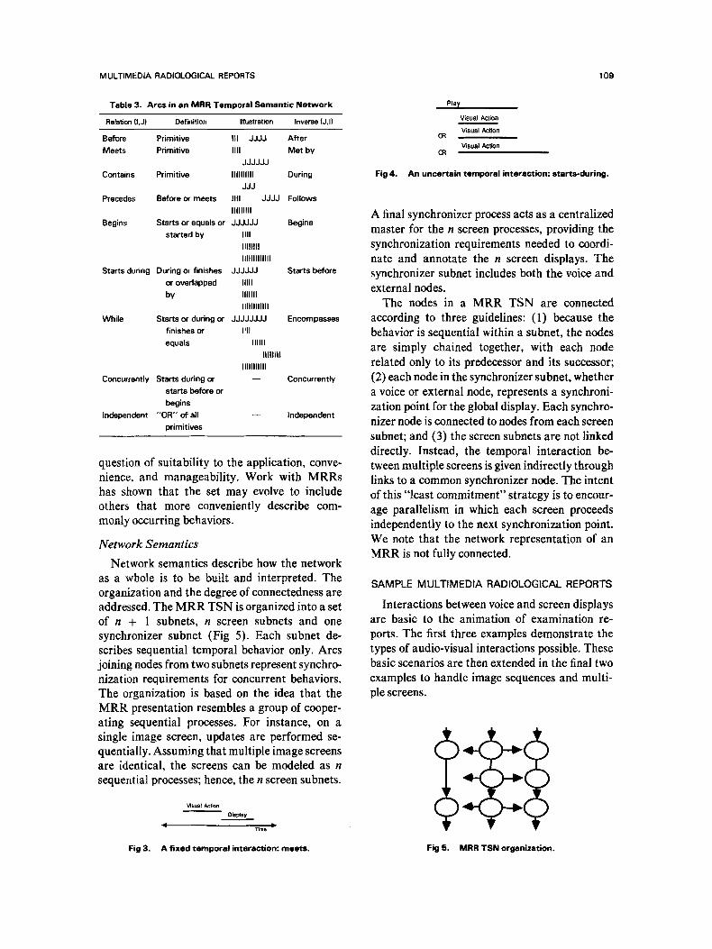
occur in an MRR can be described by this set. The initial set of temporal predicates is listed in Table 3. The selection of temporal predicates begins with the set of 13 primitive temporal relations listed in Table 1. The primitive temporal rela- tions describe fixed temporal interactions, those in which the comparative positions of all four endpoints are known. For example, as shown in Fig 3, all visual actions culminate in displays that begin as they finish. The ordering is fixed and can be described as "action meets display." There are scenarios, however, that require a less restrictive description for which defined temporal: relations are useful. For example, all visual behaviors are of random duration, making it impossible to specify when they will terminate. To describe a visual action started during the playback of a voice segment, three situations may arise, as shown in Fig 4. The defined relation starts during accounts for these three situations.
The particular choice of predicates is simply a
MULTIMEDIA RADIOLOGICAL REPORTS
Tabla 3. Arcs in en MRR Temporal Semantic Network
Relation li,J) Definition Illustration Inver (J,I)
Before Primilive I11 JJJJ After Meets Primitiva IIn Met by
JJJJJJ Contains Primitiva IIIIIIIIII During
JJJ Precedes Before or meets IIII JJJJ Follows
IIIIIIIII Begins Starts or equals or JJJJJJ Begins
started by IIII IIIit111 IIIIIIIIIIIII
Starts during During or finishes JJJJJJ Starts before or overlapped IIIII by IIIlUl
IIIIIIIIIIII While Starts of during or JJJJJJJJ Encompasses
finishes of III1 equals Illlll
llllllll IIIIIIIIIII
Concurrantly Starts during or - - Concurrently starts before or begins
tndependent "OR'" of all primitives
Independent
question of suitability to the application, conve- nience, and manageability. Work with MRRs has shown that the set may evolve to include others that more conveniently describe com- monly occurring behaviors.
Network Semantics
Network semantics describe how the network a s a whole is to be built and interpreted. The organization and the degree of connectedness are addressed. The M R R TSN is organized into a set of n + 1 subnets, n screen subnets and one synchronizer subnet (Fig 5). Each subnet de- scrt sequential temporal behavior only. Aros joining nodes from two subnets represent synchro- nization requirements for concurrent behaviors. The organization is based on the idea that the MRR presentation resembles a group of cooper- ating sequential processes. For instance, on a single image screen, updates are performed se- quentially. Assuming that multiple image screens are identical, the screens can be modeled as n sequential processes; hence, the n screen subnets.
VIsualActlon Dlsplay
4 Timo lP
Fig 4.
109
Play Visual Action Visual Action 0:~ Visual Actlon
CR
An uncertain temporal interaction: s tar ts -dur ing .
A final synchronizer process acts as a centralized master for the n screen processes, providing the synchronization requirements needed to coordi- nate and annotate the n screen displays. The synchronizer subnet includes both the voice and external nodes.
The nodes in a MRR TSN are connected according to three guidelines: (1) because the behavior is sequential within a subnet, the nodes are simply chained together, with each node related only to its predecessor and its suecessor; (2) each node in the synchronizer subnet, whether a voice of external node, represents a synchroni- zation point for the global display. Each synchro- nizer node is connected to nodes from each screen subnet; and (3) the screen subnets are not linked directly. Instead, the temporal interaction be- tween multiple screens is given indirectly through links to a common synchronizer node. The intent of this "least commitment" strategy is to encour- age parallelism in which each screen proceeds independently to the next synchronization point. We note that the network representation of an MRR is not fully connected.
SAMPLE MULTtMEDIA RADIOLOGICAL REPORTS
Interactions between voice and screen displays are basic to the animation of examination re- ports. The first three examples demonstrate the types of audio-visual interactions possible. These basic scenarios are then extended in the final two examples to handle image sequences and multi- ple screens.
Fig 3. A flxed temporal interaction: meets. Fig 5. MRR TSN orgenization.

1 10 SCHRAMM AND GOLDBERG
Scenario 1: Voice Playback With a Single Fixed Display
In this simplest scenario a voice segment is played in conjunction with a completely pre- pared, stable screen display. The TSN represen- tation given in Fig 6 describes a voice segment being played during the display shown in Fig 7. As in this example, the preparation of the screen display may actually involve a sequence of visual actions. However, the important temporal inter- action is between the voice segment and the effect of the final visual action, ie, the final screen display. Only this interaction need be specified in the TSN. In our example, the PLAY activity need not be aware of the LOAD and ZOOM actions.
Scenario 2: Voice Playback With Changing Displays
In this scenario, the reporting radiologist starts to dictate while waiting for a screen update to complete. Unlike scenario 1, the temporal inter- action is between a voice segment and a visual action. Because of the random durations of the visual actions, the relative start points can be specified but the relative end points are unknown. Figure 8 shows an example in which the radiolo- gist, while waiting for the first image to be loaded, starts dictating the report header: "Re- porting for patient John Smith on January 1."
) meets
contains
meets
' contains
meets a~
Fig 7. The display described by Fig 6.
Notice that both scenarios 1 and 2 can be easily handled because of the separation of persistent behaviors (eg, displays) from ephermeral behav- iors (eg, visual actions).
Scenario 3: Display Updates Overlap Voice Playback
This scenario is the converse of scenario 2: new visual actions are initiated during dictation. The two scenarios are not interchangeable because of the nature of voice. Consider, for explanation, the dictation timeline in Fig 9. Two situations are possible, each involving different temporal inter- actions.
The first situation is a "don't care" situation. It occurs when the voice segment does not refer to the new display created by this LOAD action. Here, the temporal interaction between the activ- ities is unimportant and can be varied. For example, if the LOAD action is expected to take longer than the given voice segment, it would be more efficient to begin the LOAD action before starting up the voice. The TSN given in Fig 10 describes a "don't care" situation.
In the second situation, some portion of the voice segment does refer to the new display. For instance, suppose the voice segment contains: "Reporting for patient John Smith on January 1,
meets
Fig 6. A sample MRR TSN for scenario 1. Fig 8. A sample MRR TSN for scenario 2.

MULTIMEDIA RADIOLOGICAL REPORTS 1 1 1
Load piŸ
Time
Fig 9. Dictation timeline.
and on this first image, the frontal view, signs of pneumonia are evident in the upper quadrant of the right lung . . . . " However, as shown in Fig 8, during dictation, the LOAD occurs so quickly that the radiologist does not need to pause. The temporal interaction is complex because: (1) different portions of the same physical voice segment are tied to different visual actions; and (2) the random duration of the visual actions means that the timing during playback may differ significantly from the timing during dicta- tion. This second situation introduces the idea of contextual segmentation. Physical voice seg- ments are subdivided into logical segments such that the temporal interactions are reduced to the simpler scenarios seen above. In our example, two logical segments would be created: (1) "Re- porting for patient John Smith on January 1"; and (2) "and on this first image, the frontal view, signs of pneumonia are evident in the upper quadrant of the right lung . . . . " T h e first logical voice segment is a "don't care" situation. The second is an example of voice playback with a fixed display. The TSN representation is in Fig 11.
Scenario 4: Voice Playback With Image Sequences
A voice segment may refer collectively to a set of screen displays. Because there are a limited number of image screens, the set may appear asa sequence. This scenario differs from contextual segmentation, in which a voice segment refers ¡ to one display and then to another display; a set is used to illustrate a single observation
r m~ets
r meets
r meets
r m 6 e t S
,3 r mee|s
Fig 11. A MRR TSN for contextual segmentation.
described in the voice segment. For instance, the progression of a disease can be traced by compar- ing a set of equivalent views taken over time. Figure 12 contains the r› for a se- quence of three images associated with the follow- ing voice segment: "Notice how the infection has spread into the lungs over the past three days." The voice segment is played as the first image is displayed. The remaining two images are se- quenced through at some controlled pace, as dictated by the two successive PAUSE nodes.
Scenario 5: Voice Playback With Multiple Image Screens
Multiple image screens involve two types of temporal interactions: the interaction between the synchronizer and the visual behaviors, and
�91
�91 ~recedes
begfns ~ / " " J
~recedes {,~,.Lo~
rneets
meets
) meets
) meets
) meets
Fig 10. An MRR TSN for a "don ' t care'" situation. Fig 12. A MRR TSN for image $equences.
112
the interaction between the multiple screens. Each synchronizer node now occurs in relation to a global display that is the combination of the visual behavior of all image screens. The single screen scenarios can be extended by adding a screen subnet for each screen and relating a node in the synchronizer subnet to the appropriate node(s) in each screen subnet. The temporal interaction between multiple screens is given indirectly by a temporal dependency on a com- mon synchronizer node. An exact record of the progress through sequences of intermediate vi- s, ual activities on the multiple screens is unimpor- tantas long as the final visual activities are all synchronized with the next synchronizer node.
MRR CREATION AND PLAYBACK
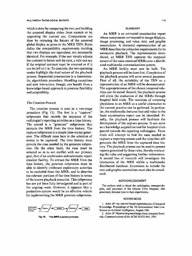
MRR creation and playback can be regarded as two processes operating in tandem to perform an automatic two-step transformation of the radiologist's reporting activities into an MRR presentation (Fig 13). We will first discuss the playback process and then conclude with the creation process.
The Playback Process
The playback process automatically coordi- nates the manipulation of the voice system and n image screens according to the specifications given in the MRR. The playback process has two modes of operation: sequential execution and interrupt execution.
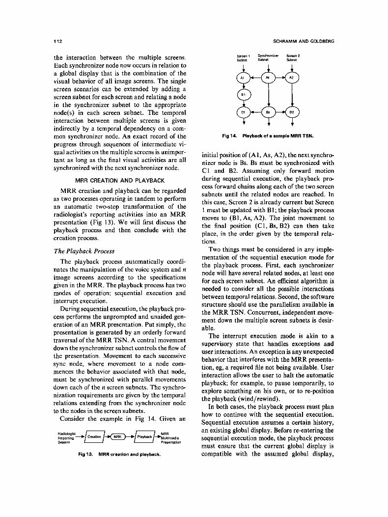
During sequential execution, the playback pro- cess performs the unprompted and unaided gen- eration of an MRR presentation. Put simply, the presentation is generated by an orderly forward traversal of the MRR TSN. A central movement down the synchronizer subnet controls the flow of the presentation. Movement to each successive sync node, where movement to a node com- mences the behavior associated with that node, must be synchronized with parallel movements down each of the n screen subnets. The synchro- nization requirements are given by the temporal relations extending from the synchronizer node to the nodes in the screen subnets.
Consider the example in Fig 14. Given an
Radiologist ~ ~ / ~ / MRR Reporting -~11~/Creation /---I~ MRR ~-~11~/Playback/.--~p ultirnedia Session I t Presentation
Fig 13. MRR creation and playback.
SCHRAMM AND GOLDBERG
Screen 1 Synchronizer Screen 2 Subnet Subnet Subnet
Fig 14. Playback of a sample MRR TSN.
initial position of (A 1, As, A2), the next synchro- nizer node is Bs. Bs must be synchronized with C1 and B2. Assuming only forward motion during sequential execution, the playback pro- cess forward chains along each of the two screen subnets until the related nodes are reached. In this case, Screen 2 is already current but Screen 1 must be updated with B 1; the playback process moves to (B1, As, A2). The joint movement to the final position (C1, Bs, B2) can then take place, in the order given by the temporal rela- tions.
Two things must be considered in any imple- mentation of the sequential execution mode for the playback process. First, each synchronizer node will have several related nodes, at least one for each screen subnet. An efficient algorithm is needed to consider all the possible interactions between temporal relations. Second, the software structure should use the parallelism available in the MRR TSN. Concurrent, independent move- ment down the multiple screen subnets is desir- able,
The interrupt execution mode is akin to a supervisory state that handles exceptions and user interactions. An exception is any unexpected behavior that interferes with the MRR presenta- tion, eg, a required file not being available. User interaction allows the user to halt the automatic playback; for example, to pause temporarily, to explore something on his own, or to re-position the playback (wind/rewind).
In both cases, the playback process must plan how to continue with the sequential execution. Sequential execution assumes a certain history, an existing global display. Before re-entering the sequential execution mode, the playback process must ensure that the current global display is compatible with the assumed global display,
MULTIMEOlA RADIOLOGICAL REPORTS 1 13
which is done by comparing the two, and building the assumed display either from scratch or by upgrading the current one. Comparisons are done by retracing the history of the assumed global display as given in the MRR TSN. Rules define the compatibility requirements deciding that two displays are equivalent, not necessarily identical. For example, if the user simply adjusts the contrast to better suit his eyes, a rule can say if the original contrast must be restored or if it can be left as it is. To conclude, the two operating modes highlight the dual nature of the playback process. Sequential presentation is a determinis- tic, algorithmic procedure. Handling exceptions and user interaction, though, can benefit from a knowledge-based approach to promote flexibility and adaptability.
The Creation Process
The creation process is seen as a two-stage procedure (Fig 15). The first is a "capture" subprocess that records the sequence of the radiologist's reporting activities asa time history. The second is a "generate" subprocess that extracts the M R R from the time history. The capture subprocess is a simple time-stamp gener- ator. The difficult issue here is the selection of events to be captured. The time history must provide the cues needed by the generate subpro- cess. On the other hand, the cues must be selected so as to not conflict with our primary goal, that of ah unobtrusive and automatic report creation facility. To extract the MRR from the time history, the generate subprocess must be able to identify irrelevant exploratory activities to be excluded from the MRR, and to describe the relevant portions of the time history in terms of the known playback scenarios. This subprocess has not yet been fully investigated and is part of the ongoing work. However, it appears that a production system would be an effective vehicle for implementing the MRR generate subprocess.
Fig 15. The MRR creation pror
SUMMARY
An MRR is an animated examination report whose components correspond to image displays, image processing, and voice, text, and graphic annotations. A temporal representation of an MRR describes the animation requirements for its automatic playback. The representation intro- duced, an MRR TSN captures the temporal nature of the voice-centered MRRs over a distrib- uted multimedia communications system.
An M R R facility must now be built. The playback process will be done first. Completion of the playback process will serve several purposes. First of all, the suitability of the TSN a s a representation of an MRR will be demonstratcd. The appropriateness of the chosen temporal rela- tions can be tested. Second, the playback process will allow the evaluation of the MRRs through hospital field trials. The reactions of reviewing physicians to an MRR as a useful alternative to the current practice can be gathered. In particu- lar, the multimedia features that add value to the basic examination report can be identified. Fi- nally, the playback process will facilitate the development of the capture process. It can serve as a knowledge acquisition tool for hospital trials geared towards the reporting radiologists. These trials will attempt to find the cues needed to capture a reporting session and the rules that will generate the MRR from the captured time his- tory. The playback process can be used to present reports generated by these rules, thereby evaluat- ing the rules and suggesting further refinements. A second line of research will investigate the interaction of the MRR within a multimedia distributed database. Extensions to include the text and graphic annotations must also be consid- ered.
ACKNOWLEDGMENT
The authors wish to thank the radiologists, emergentolo- gists, and personnel of the Ottawa Civic Hospital, who generously donated time to their experiments.
REFERENCES
i. Allen JF: An interval-based representation of temporal Knowledge. Proceedings of the 7th Internationat Joint Con- ference on Artificial Intelligence, August 1981
2. Allen JF: Maintaining knowledge about temporal Inter- vals. Communications of the ACM 26:832-843, 1983