multilevel full-chip gridless routing with …cc.ee.ntu.edu.tw › ~ywchang › papers ›...
TRANSCRIPT

IEEE TRANSACTIONS ON COMPUTER-AIDED DESIGN OF INTEGRATED CIRCUITS AND SYSTEMS, VOL. 26, NO. 6, JUNE 2007 1041
Multilevel Full-Chip Gridless Routing WithApplications to Optical-Proximity Correction
Tai-Chen Chen, Student Member, IEEE, and Yao-Wen Chang, Member, IEEE
Abstract—To handle modern routing with nanometer effects,we need to consider designs with variable wire/via widths andspacings, for which gridless-routing approaches are desirable dueto its great flexibility. In this paper, we introduce a gridless-routing model that can obtain design-rule-correct paths and avoidredundant wires. Besides, we propose an enhanced model for thegridless-routing model to reduce the solution space and the run-time. Based on the enhanced gridless-routing model, we presentthe first multilevel full-chip gridless detailed router (called MGR).The router integrates global routing, detailed routing, and con-gestion estimation together at each level of multilevel routing. Itcan handle designs with nonuniform wire/via widths and spacingsand consider routability and optical-proximity correction. Exper-imental results show that MGR achieves the best routing solutionsin smaller running times than previous works, based on a set ofcommonly used benchmarks (with uniform and nonuniform wirewidths) and a set of real industrial benchmarks (with a versatileset of design rules).
Index Terms—Design for manufacturing (DFM), gridless rout-ing, multilevel optimization, optical-proximity correction (OPC),physical design, routing.
I. INTRODUCTION
R ESEARCH in very large-scale integration (VLSI) routinghas received much attention in the literature. Routing is
typically a very complex combinatorial problem. In order tomake it manageable, the routing problem is usually solvedusing the two-stage approach of global routing followed bydetailed routing. Global routing first partitions the routing areainto tiles and decides tile-to-tile paths for all nets, while detailedrouting assigns actual tracks and vias for nets. Many routingalgorithms adopt a flat framework of finding paths for allnets. Those algorithms can be classified into sequential andconcurrent approaches. Early sequential-routing algorithms in-clude maze-searching [28], [42] and line-searching approaches[18], which route net-by-net. Most concurrent algorithms ap-ply network-flow or linear-assignment formulation [2], [37] toroute a set of nets at one time.
Manuscript received October 8, 2005; revised April 1, 2006. This work wassupported in part by SpringSoft, Inc., and the National Science Council ofTaiwan, under Grants NSC 93-2215-E-002-009 and NSC 93-2215-E-002-029.This paper was presented in part at the 2005 ACM/IEEE Asia and South PacificDesign Automation Conference [7]. This paper was recommended by AssociateEditor T. Yoshimura.
T.-C. Chen is with the Graduate Institute of Electronics Engineering,National Taiwan University, Taipei 106, Taiwan, R.O.C. (e-mail: [email protected]).
Y.-W. Chang is with the Department of Electrical Engineering and GraduateInstitute of Electronics Engineering, National Taiwan University, Taipei 106,Taiwan, R.O.C. (e-mail: [email protected]).
Digital Object Identifier 10.1109/TCAD.2006.884492
The major problem of the flat frameworks lies in theirscalability for handling larger designs. As technology advances,technology nodes are getting smaller and circuit sizes are get-ting larger. To cope with the increasing complexity, researchersproposed to use hierarchical approaches to handle the problem:Marek-Sadowska in [35] proposed a hierarchical global routerbased on linear assignment; Heisterman and Lengauer in [17]presented a hierarchical integer-linear programming approachfor global routing; Wang and Kuh in [44] proposed a hierar-chical (α, β)∗ algorithm for timing-driven multilayer MCM/ICrouting; Chang et al. in [5] applied linear assignment to developa hierarchical, concurrent global, and detailed router for fieldprogrammable gate arrays.
The two-level hierarchical routing framework, however, isstill limited in handling the dramatically growing complexityand maintaining high-solution quality at the same time incurrent and future IC designs, which may contain billions oftransistors in a single chip. As pointed out in [12], for a 0.07-µmprocess technology, a 2.5 × 2.5 cm2 chip may contain over360 000 horizontal and vertical routing tracks. To handle suchhigh design complexity, the two-level hierarchical approachbecomes insufficient. Therefore, it is desired to employ morelevels of routing for larger IC designs.
A. Multilevel Routing
The multilevel framework has attracted much attention in theliterature recently. It employs a two-stage technique: coarseningfollowed by uncoarsening. The coarsening stage iterativelygroups a set of circuit components (e.g., circuit nodes, cells,modules, routing tiles, etc.) based on a predefined cost metricuntil the number of components being considered is smallerthan a threshold. Then, the uncoarsening stage iteratively un-groups a set of previously clustered circuit components andrefines the solution by using a combinatorial optimizationtechnique (e.g., simulated annealing, local refinement, etc.).The multilevel framework has been successfully applied toVLSI physical design. For example, the famous multilevelpartitioners ML [3], HPM [10], and hMETIS [26], the multi-level floorplanner/placer MB∗ − tree [29], and the multilevelplacers mPL [4] and APlace [24], [25] all show the promiseof the multilevel framework for large-scale circuit partitioning,floorplanning, and placement.
A framework similar to multilevel routing was presentedin [16], [30], and [34]. Lin et al. in [30] and Hayashi andTsukiyama in [16] presented hybrid hierarchical global routersfor multilayer VLSIs, in which both bottom–up (coarsening)and top–down (uncoarsening) techniques were used for global
0278-0070/$25.00 © 2007 IEEE

1042 IEEE TRANSACTIONS ON COMPUTER-AIDED DESIGN OF INTEGRATED CIRCUITS AND SYSTEMS, VOL. 26, NO. 6, JUNE 2007
Fig. 1. (a) Routing example. s and t are the source and target of a routing wire, respectively. The two rectangles represent obstacles. (b) Uniform-grid model. Theblack and white circles denote the routable and unroutable nodes, respectively. (c) Tile-based model. (d) Nonuniform-grid model. (e) Implicit nonuniform-gridmodel. (f) Nonuniform-grid graph model. The gray areas denote the obstacle zones constructed by expanding obstacles according to design rules.
routing. Marek-Sadowska in [34] proposed a global routerbased on the outer most loop approach. The approach is similarto the coarsening stage of multilevel routing. Cong et al. in[12] proposed a pioneering routability-driven multilevel global-routing approach for large-scale full-chip routing. Cong et al.later proposed an enhanced multilevel-routing system, namedMARS, which incorporates resource reservation, a graph-basedSteiner tree heuristic, and a history-based multiiteration schemeto improve the quality of the multilevel-routing algorithm in[13] and [14]. Their final results of the multilevel global routingare tile-to-tile paths for all nets. The results are then fed into anonmultilevel gridless detailed router, called DUNE [9], [11],to find the exact connection for each net (therefore, MARSis in fact a multilevel global router, but not a detailed router).Lin and Chang in [6] and [31] proposed a multilevel approachfor full-chip grid-based routing, which considers both routabil-ity and performance. This framework integrates grid-basedglobal routing, detailed routing, and resource estimation to-gether at each level, leading to more accurate routing-resourceestimation during coarsening and, thus, facilitating the solu-tion refinement during uncoarsening. Their experimental re-sults show the best routability among the previous works forgrid-based routing. Recently, Ho et al. in [19]–[21] presentedanother multilevel framework for full-chip grid-based routingconsidering crosstalk and antenna effects, respectively. Theframework incorporates an intermediate stage of layer/trackassignment between the coarsening stage and the uncoarsen-ing stage. The coarsening stage performs only global routingwhile global and detailed routing are integrated together at theuncoarsening stage.
B. Gridless Detailed Routing
In the detailed-routing stage, seeking design-rule-correctpaths in the routing region is a major concern. Traditionaldetailed routings use uniform-grid models to simplify the prob-lem, as shown in Fig. 1(b). However, uniform-grid models needvery fine grids to handle nonuniform wire/via widths and spac-ings, implying larger searching time and storage requirements.Therefore, the grid-based approach is not effective to handle
modern routing problems with nanometer electrical effects,such as optical-proximity correction (OPC) and phase-shiftmask. To cope with these nanometer electrical effects, gridless-routing models are desirable due to their great flexibility.
Several gridless-detailed-routing models have been investi-gated and can be classified into two types: tile-based models[32], [33], [36], [40], [43], [47] and connection-graph models[8], [23], [38], [45], [48]. As shown in Fig. 1(c), the tile-based model partitions the routing region into tiles along theboundaries of obstacles and represents the routing region bya data structure such as corner stitching [39]. Therefore, therouting problem is reduced to searching a tile-to-tile pathamong these tiles. Although searching a tile-to-tile path is fast,manipulating tiles such as insertion and deletion is a complexprocess. Furthermore, it needs postprocessing to obtain a finaldesign-rule-correct route for the tile-to-tile path. Moreover, itis not easy to apply the tile-based models to multilayer routingwith more complex design rules [12].
As shown in Fig. 1(d), Ohtsuki in [38] proposed anonuniform-grid model, which was constructed by extend-ing lines through the boundaries of all obstacles until theyintersect with other obstacles or boundaries of the routingregion. Because the preconstruction and representation of thenonuniform-grid model are costly, previous works [8], [23],[45] tried to simplify the nonuniform-grid model by vari-ous techniques. However, those techniques are still costlyfor large-scale designs. As shown in Fig. 1(e), Zheng et al.in [48] presented an implicit nonuniform-grid model, whichdoes not construct a connection graph explicitly and charac-terizes the search space in an on-the-fly fashion during routing.Schiele et al. in [41] constructed the obstacle zones from theobstacles by taking design rules into account. The area outsideof the obstacle zones is available for placing the center linesof wires and midpoints of contacts. As shown in Fig. 1(f),Cong et al. in [9] and [11] integrated the concepts of obstacleszones [41] and the implicit nonuniform-grid model [48] tobuild their nonuniform-grid-graph (NGG) model. Although theNGG model has the advantages of fast implicit connectiongraph construction, routing based on the NGG model may incurdesign-rule-incorrect paths. Furthermore, routing based on the

CHEN AND CHANG: MULTILEVEL FULL-CHIP GRIDLESS ROUTING 1043
Fig. 2. (a) Optical-proximity effects (courtesy of Synopsys). Three majorOPC techniques: (b) Serif; (c) Hammerhead; and (d) Line Biasing.
NGG model may result in redundant wires even using point-to-path maze routing.
C. OPC Technologies
As the process technology continues to advance, the min-imum feature size of circuit patterns becomes significantlysmaller than the lithographic wavelength. As a result, it isvery hard to obtain the exact image we desire on the wafer.Resolution enhancement techniques, such as OPC, are neededto achieve acceptable process accuracy.
Applying optics simulation, we can clearly see this variationas shown in Fig. 2(a). These variations can be classified intomainly three types: corner rounding, line-end shortening, andlinewidth shrinking, as shown in Fig. 2(b)–(d). (Here, a line isa horizontal/vertical segment of a net or a via.) For each typeof variations, we can add pattern features to compensate forthe distortions and acquire what we really need on the resist.We can add serifs at corners to make the angles sharper, addhammerheads at line ends to compensate for their shortenings,and add line biasings along line sides to compensate for theirshrinkings.
OPC might incur a much larger number of pattern features,implying larger memory requirements to record these featuresand higher mask costs. More than a five times increases indata volume and several days of additional CPU runtime arecommon side effects of OPC insertion in current designs [15]. Ifa router can generate the configurations that require fewer shotsto OPC, we can reduce the data volume for OPC. Therefore, itis desired to consider the optical effects to reduce the numberof pattern features.
As a relatively new issue, there is not much work in theliterature on routing with the OPC consideration. Huang andWong in [22] presented a pioneering work on OPC-friendlymaze routing based on the Lagrangian relation formulation.However, the router is grid based and considers only two-pinconnections. Furthermore, it uses the flat framework and, thus,cannot handle the problem sizes of thousands of nets well.Recently, Wu et al. in [46] presented an enhanced maze routingto solve two OPC-aware maze-routing problems. However, thegoals of both problems are to find the single-routing path ofthe kth net when a routing region with k − 1 routed pathsof two-pin nets are given. Although their method can find arouting path for the kth net under different constraints andobjective functions, it does not consider multipin nets and thenet ordering problems.
D. Our Contribution
In this paper, we propose the first multilevel full-chip grid-less detailed router. The four main features of the proposedmethod are as follows: 1) A gridless-routing model and itsenhanced model that can obtain design-rule-correct paths andavoid redundant wires; 2) the first multilevel gridless routerthat integrates gridless global and detailed routings; 3) a multi-level gridless router that can handle designs with nonuniformwire/via widths and spacing; and 4) a routability-driven andOPC-aware multilevel gridless router that can optimize routing-completion rates and reduce OPC-pattern feature requirements.
Experimental results show that our multilevel gridless router(called MGR) achieves 100% routing-completion rates withless running times than previous works based on a set ofcommonly used Microelectronics Center of North Carolina(MCNC) benchmarks. Furthermore, MGR can handle designswith nonuniform wire widths well and obtain better routingsolutions (still maintain 100% routing completion for all cir-cuits) than the state-of-the-art multilevel gridless-routing sys-tem (multilevel gridless global routing + flat gridless detailedrouting) [14]. In particular, MGR is the first router to completethe routing for the set of commonly used MCNC benchmarks ofnonuniform wire sizes and to route the real industrial Faradaybenchmarks with a versatile set of design rules. Moreover, ourOPC-aware MGR archives an average reduction of 9% patternfeatures and still maintains 100% routability for the 11 MCNC-benchmark circuits.
The rest of this paper is organized as follows. Section IIpresents the global, detailed, and multilevel-routing mod-els. Section III presents our framework for routability-drivenand OPC-aware routings. Experimental results are shown inSection IV. Finally, we give concluding remarks in Section V.
II. PRELIMINARIES
Routing in modern ICs is a very complex process, and wecan hardly obtain high-quality solutions directly. Therefore, therouting problem is usually solved using the two-stage approachof global routing followed by detailed routing. Global routingfirst partitions the routing area into tiles and decides tile-to-tilepaths for all nets, while detailed routing assigns actual tracksand vias for nets.
A. Modeling of Global Routing
Our global-routing algorithm is based on a graph-searchtechnique guided by the congestion associated with routingregions and topologies. The router assigns higher costs to routenets through congested areas to balance the net distributionamong routing regions.
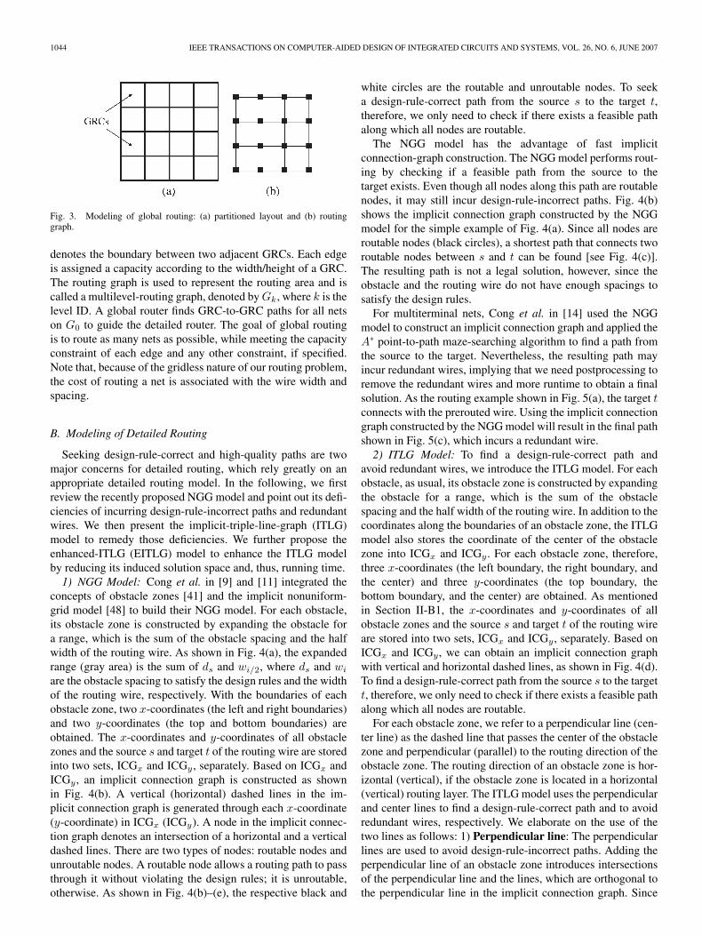
Before we can apply the graph-search technique to multilevelrouting, we first need to model the routing resource as a graphsuch that the graph topology can represent the chip structure.Fig. 3 illustrates the graph modeling. For the modeling, we firstpartition a chip into an array of rectangular subregions. Thesesubregions are called global-routing cells (GRCs). A node inthe routing graph represents a GRC in the chip, and an edge
1044 IEEE TRANSACTIONS ON COMPUTER-AIDED DESIGN OF INTEGRATED CIRCUITS AND SYSTEMS, VOL. 26, NO. 6, JUNE 2007
Fig. 3. Modeling of global routing: (a) partitioned layout and (b) routinggraph.
denotes the boundary between two adjacent GRCs. Each edgeis assigned a capacity according to the width/height of a GRC.The routing graph is used to represent the routing area and iscalled a multilevel-routing graph, denoted byGk, where k is thelevel ID. A global router finds GRC-to-GRC paths for all netson G0 to guide the detailed router. The goal of global routingis to route as many nets as possible, while meeting the capacityconstraint of each edge and any other constraint, if specified.Note that, because of the gridless nature of our routing problem,the cost of routing a net is associated with the wire width andspacing.
B. Modeling of Detailed Routing
Seeking design-rule-correct and high-quality paths are twomajor concerns for detailed routing, which rely greatly on anappropriate detailed routing model. In the following, we firstreview the recently proposed NGG model and point out its defi-ciencies of incurring design-rule-incorrect paths and redundantwires. We then present the implicit-triple-line-graph (ITLG)model to remedy those deficiencies. We further propose theenhanced-ITLG (EITLG) model to enhance the ITLG modelby reducing its induced solution space and, thus, running time.1) NGG Model: Cong et al. in [9] and [11] integrated the
concepts of obstacle zones [41] and the implicit nonuniform-grid model [48] to build their NGG model. For each obstacle,its obstacle zone is constructed by expanding the obstacle fora range, which is the sum of the obstacle spacing and the halfwidth of the routing wire. As shown in Fig. 4(a), the expandedrange (gray area) is the sum of ds and wi/2, where ds and wi
are the obstacle spacing to satisfy the design rules and the widthof the routing wire, respectively. With the boundaries of eachobstacle zone, two x-coordinates (the left and right boundaries)and two y-coordinates (the top and bottom boundaries) areobtained. The x-coordinates and y-coordinates of all obstaclezones and the source s and target t of the routing wire are storedinto two sets, ICGx and ICGy , separately. Based on ICGx andICGy , an implicit connection graph is constructed as shownin Fig. 4(b). A vertical (horizontal) dashed lines in the im-plicit connection graph is generated through each x-coordinate(y-coordinate) in ICGx (ICGy). A node in the implicit connec-tion graph denotes an intersection of a horizontal and a verticaldashed lines. There are two types of nodes: routable nodes andunroutable nodes. A routable node allows a routing path to passthrough it without violating the design rules; it is unroutable,otherwise. As shown in Fig. 4(b)–(e), the respective black and
white circles are the routable and unroutable nodes. To seeka design-rule-correct path from the source s to the target t,therefore, we only need to check if there exists a feasible pathalong which all nodes are routable.
The NGG model has the advantage of fast implicitconnection-graph construction. The NGG model performs rout-ing by checking if a feasible path from the source to thetarget exists. Even though all nodes along this path are routablenodes, it may still incur design-rule-incorrect paths. Fig. 4(b)shows the implicit connection graph constructed by the NGGmodel for the simple example of Fig. 4(a). Since all nodes areroutable nodes (black circles), a shortest path that connects tworoutable nodes between s and t can be found [see Fig. 4(c)].The resulting path is not a legal solution, however, since theobstacle and the routing wire do not have enough spacings tosatisfy the design rules.
For multiterminal nets, Cong et al. in [14] used the NGGmodel to construct an implicit connection graph and applied theA∗ point-to-path maze-searching algorithm to find a path fromthe source to the target. Nevertheless, the resulting path mayincur redundant wires, implying that we need postprocessing toremove the redundant wires and more runtime to obtain a finalsolution. As the routing example shown in Fig. 5(a), the target tconnects with the prerouted wire. Using the implicit connectiongraph constructed by the NGG model will result in the final pathshown in Fig. 5(c), which incurs a redundant wire.2) ITLG Model: To find a design-rule-correct path and
avoid redundant wires, we introduce the ITLG model. For eachobstacle, as usual, its obstacle zone is constructed by expandingthe obstacle for a range, which is the sum of the obstaclespacing and the half width of the routing wire. In addition to thecoordinates along the boundaries of an obstacle zone, the ITLGmodel also stores the coordinate of the center of the obstaclezone into ICGx and ICGy . For each obstacle zone, therefore,three x-coordinates (the left boundary, the right boundary, andthe center) and three y-coordinates (the top boundary, thebottom boundary, and the center) are obtained. As mentionedin Section II-B1, the x-coordinates and y-coordinates of allobstacle zones and the source s and target t of the routing wireare stored into two sets, ICGx and ICGy , separately. Based onICGx and ICGy , we can obtain an implicit connection graphwith vertical and horizontal dashed lines, as shown in Fig. 4(d).To find a design-rule-correct path from the source s to the targett, therefore, we only need to check if there exists a feasible pathalong which all nodes are routable.
For each obstacle zone, we refer to a perpendicular line (cen-ter line) as the dashed line that passes the center of the obstaclezone and perpendicular (parallel) to the routing direction of theobstacle zone. The routing direction of an obstacle zone is hor-izontal (vertical), if the obstacle zone is located in a horizontal(vertical) routing layer. The ITLG model uses the perpendicularand center lines to find a design-rule-correct path and to avoidredundant wires, respectively. We elaborate on the use of thetwo lines as follows: 1) Perpendicular line: The perpendicularlines are used to avoid design-rule-incorrect paths. Adding theperpendicular line of an obstacle zone introduces intersectionsof the perpendicular line and the lines, which are orthogonal tothe perpendicular line in the implicit connection graph. Since

CHEN AND CHANG: MULTILEVEL FULL-CHIP GRIDLESS ROUTING 1045
Fig. 4. (a) Routing example. The gray area denotes the obstacle zone constructed by expanding a range, which is the sum of the wire spacing and the half widthof the routing wire. ds and wi are wire/via spacing that satisfies the design rules and the width of the routing wire, respectively. s and t are the source and target ofthe routing wire, respectively. (b) Implicit connection graph constructed by the NGG model. The black circles denote the routable nodes. (c) Design-rule-incorrectpath, for which the obstacle and the routing wire do not have enough spacings. (d) Implicit connection graph constructed by our ITLG model. The black and whitecircles denote the routable and unroutable nodes, respectively. (e) Design-rule-correct path found through five routable nodes.
Fig. 5. (a) Routing example. The gray areas denote the obstacle zones constructed by expanding a range, which is the sum of the wire spacing and the half widthof the routing wire. The horizontal (vertical) edge of the prerouted wire is in a horizontal (vertical) routing layer. The target of the routing wire t connects with theprerouted wire. ds and wi are the obstacle spacing that satisfies the design rules and the width of the routing wire, respectively. s and t are the source and targetof the routing wire, respectively. (b) Implicit connection graph constructed by the NGG model. The black circles denote the routable nodes. Since t connects withthe prerouted wire, the nodes in the obstacle are routable nodes. (c) Path is found through four routable nodes and incurs a redundant wire between the preroutedwire and the routing wire. (d) Implicit connection graph constructed by our ITLG model. The gray circles denote the touch nodes. (e) Path is found through tworoutable nodes and incurs no redundant wire between the prerouted wire and the routing wire.
the nodes (intersections) are located inside the obstacle zone,they are unroutable nodes. These unroutable nodes can be usedto avoid a path from crossing the obstacle zone directly. Asshown in Fig. 4(d), the white circle is introduced by the perpen-dicular line and is an unroutable node. With the unroutable nodein mind, we can find the design-rule-correct, detour path shownin Fig. 4(e) and avoid the design-rule-incorrect path shown inFig. 4(c). 2) Center line: The center lines are used to avoidredundant wires. Adding the center line of an obstacle zone
introduces intersections of the center line and the lines, whichare orthogonal to the center line in the implicit connectiongraph. Nodes (intersections) located inside target obstacles aretouch nodes, which are also routable nodes. Target obstaclesdenote obstacles (prerouted wires), which are connected withthe target of the routing wire. If the source of the routing wireconnects with one of these touch nodes, the source and thetarget are connected. Therefore, we can find a path from thesource to one of the touch nodes to avoid redundant wires. As

1046 IEEE TRANSACTIONS ON COMPUTER-AIDED DESIGN OF INTEGRATED CIRCUITS AND SYSTEMS, VOL. 26, NO. 6, JUNE 2007
Fig. 6. (a) Routing example. The gray areas denote the obstacle zones constructed by expanding a range which is the sum of the wire spacing and the half widthof the routing wire. The target of the routing wire connects with the prerouted wire in the left side. ds and wi are wire/via spacing that satisfies the design rulesand the width of the routing wire, respectively. s and t are the respective source and target of the routing wire. (b) Implicit connection graph constructed by ourITLG model. The total number of nodes is 9 × 10. (c) Implicit connection graph constructed by our EITLG model. The total number of nodes is reduced to7 × 8. The black, white, and gray circles denote the routable, unroutable, and touch nodes, respectively. Because the target of the routing wire connects with theprerouted wire in the left side, the nodes located above the obstacle zones in the left (right) side are routable (unroutable) nodes.
shown in Fig. 5(d), touch nodes are located inside the preroutedwire. Therefore, we can find a shorter path with nonredundantwires shown in Fig. 5(e).3) EITLG Model: Although the ITLG model can avoid
design-rule-incorrect paths and redundant wires, the inducedsolution space (the total number of nodes) of the ITLG modelmay be more than twice of that of the NGG model, implyinglarger runtime and storage requirements. Therefore, we shallpropose an enhanced model, called the EITLG model, to reducethe solution space of the ITLG model.
We show how to reduce the solution space of the ITLGmodel as follows: 1) Perpendicular line: To avoid a design-rule-incorrect path, the ITLG model uses the perpendicularlines of all obstacle zones to identify unroutable nodes locatedinside the zones to avoid a path from crossing the zone directly.If there exists a line parallel to the perpendicular line of anobstacle zone and passing through the zone, this line canintroduce unroutable nodes inside the zone, too. Since both ofthis line and the perpendicular line can introduce unroutablenodes inside the obstacle zone, we do not need to constructthe perpendicular line. As shown in Fig. 6, each obstacle zonecontains lines perpendicular to the routing direction of the zoneand passing through the zone. Therefore, the EITLG modeldoes not construct the perpendicular line for each obstacle zone,as shown in Fig. 6(c), reducing significant solution space fordetailed routing. 2) Center line: To avoid redundant wires, theITLG model uses center lines of all obstacle zones to generatenodes. Since only the nodes located inside target obstacles aretouch nodes, we only need to construct the center lines of thetarget obstacles (obstacle zones). As shown in Fig. 6, only thetwo obstacles in the left side connect with the target. Therefore,the EITLG model does not construct the center line of theobstacle in the right side of Fig. 6(c).
Algorithm ICG construction, shown in Fig. 7, constructsICGx and ICGy for routing a wire from the source s to thetarget t based on the EITLG model. The time complexity ofthis algorithm is O(n lg n) by implementing the two sets ICGx
and ICGy with two sorted arrays, where n is the total numberof obstacle zones.
Fig. 7. Algorithm to construct ICGx and ICGy for routing a wire from thesource s to the target t based on the EITLG model.
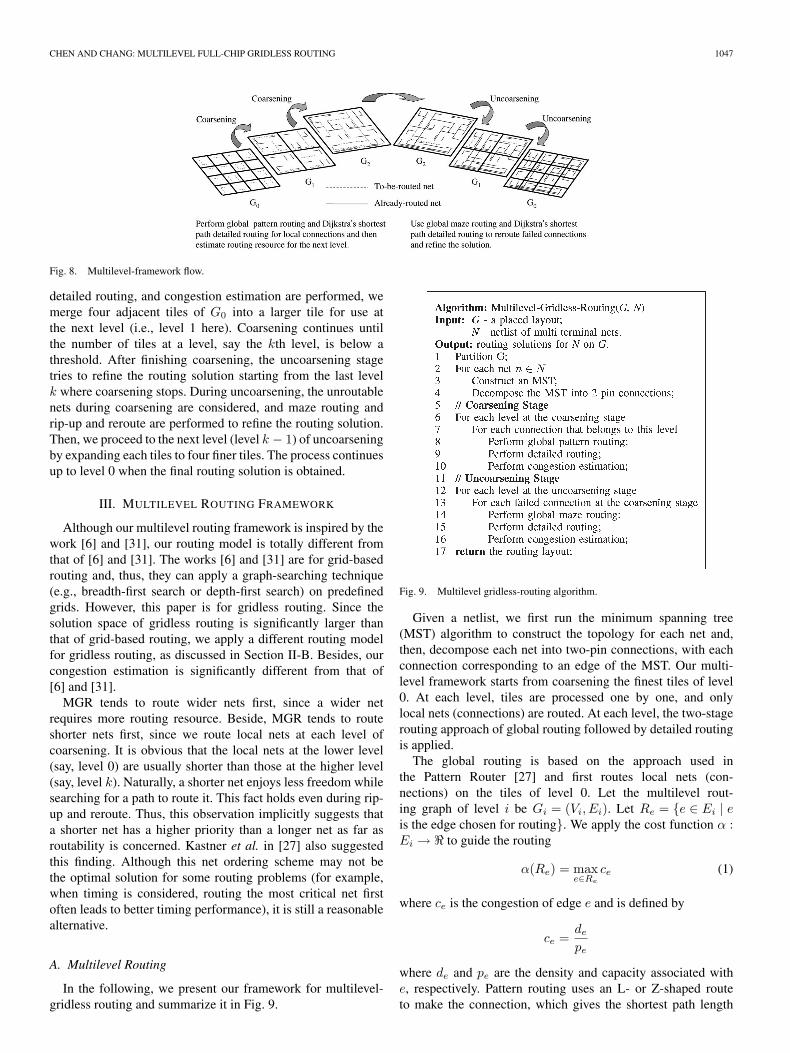
C. Modeling of Multilevel Routing
Fig. 8 shows our multilevel framework. As illustrated inFig. 8, G0 corresponds to the routing graph of the level 0of the multilevel-coarsening stage. At each level, our globalrouter first finds routing paths for the local nets (or local 2-pinconnections) (those nets [connections] that entirely sit insidea tile) and, then, the detailed router is used to determine theexact wiring. The congestion estimation is performed after thedetailed routing finishes routing a net. After the global routing,
CHEN AND CHANG: MULTILEVEL FULL-CHIP GRIDLESS ROUTING 1047
Fig. 8. Multilevel-framework flow.
detailed routing, and congestion estimation are performed, wemerge four adjacent tiles of G0 into a larger tile for use atthe next level (i.e., level 1 here). Coarsening continues untilthe number of tiles at a level, say the kth level, is below athreshold. After finishing coarsening, the uncoarsening stagetries to refine the routing solution starting from the last levelk where coarsening stops. During uncoarsening, the unroutablenets during coarsening are considered, and maze routing andrip-up and reroute are performed to refine the routing solution.Then, we proceed to the next level (level k − 1) of uncoarseningby expanding each tiles to four finer tiles. The process continuesup to level 0 when the final routing solution is obtained.
III. MULTILEVEL ROUTING FRAMEWORK
Although our multilevel routing framework is inspired by thework [6] and [31], our routing model is totally different fromthat of [6] and [31]. The works [6] and [31] are for grid-basedrouting and, thus, they can apply a graph-searching technique(e.g., breadth-first search or depth-first search) on predefinedgrids. However, this paper is for gridless routing. Since thesolution space of gridless routing is significantly larger thanthat of grid-based routing, we apply a different routing modelfor gridless routing, as discussed in Section II-B. Besides, ourcongestion estimation is significantly different from that of[6] and [31].
MGR tends to route wider nets first, since a wider netrequires more routing resource. Beside, MGR tends to routeshorter nets first, since we route local nets at each level ofcoarsening. It is obvious that the local nets at the lower level(say, level 0) are usually shorter than those at the higher level(say, level k). Naturally, a shorter net enjoys less freedom whilesearching for a path to route it. This fact holds even during rip-up and reroute. Thus, this observation implicitly suggests thata shorter net has a higher priority than a longer net as far asroutability is concerned. Kastner et al. in [27] also suggestedthis finding. Although this net ordering scheme may not bethe optimal solution for some routing problems (for example,when timing is considered, routing the most critical net firstoften leads to better timing performance), it is still a reasonablealternative.
A. Multilevel Routing
In the following, we present our framework for multilevel-gridless routing and summarize it in Fig. 9.
Fig. 9. Multilevel gridless-routing algorithm.
Given a netlist, we first run the minimum spanning tree(MST) algorithm to construct the topology for each net and,then, decompose each net into two-pin connections, with eachconnection corresponding to an edge of the MST. Our multi-level framework starts from coarsening the finest tiles of level0. At each level, tiles are processed one by one, and onlylocal nets (connections) are routed. At each level, the two-stagerouting approach of global routing followed by detailed routingis applied.
The global routing is based on the approach used inthe Pattern Router [27] and first routes local nets (con-nections) on the tiles of level 0. Let the multilevel rout-ing graph of level i be Gi = (Vi, Ei). Let Re = {e ∈ Ei | eis the edge chosen for routing}. We apply the cost function α :Ei → to guide the routing
α(Re) = maxe∈Re
ce (1)
where ce is the congestion of edge e and is defined by
ce =de
pe
where de and pe are the density and capacity associated withe, respectively. Pattern routing uses an L- or Z-shaped routeto make the connection, which gives the shortest path length

1048 IEEE TRANSACTIONS ON COMPUTER-AIDED DESIGN OF INTEGRATED CIRCUITS AND SYSTEMS, VOL. 26, NO. 6, JUNE 2007
between two points. Therefore, the wire length is minimum. Wemeasure the routing congestion based on the channel densitydefined by the sum of wire spacing and wire width for gridlessrouting (note that the definition is different from the casein grid-based routing, for which channel density is definedas the maximum number of parallel nets passing through arouting channel). If pattern routing fails, we give up routingthe connection. We refer to a failed net (failed connection) asthat causes an overflow. The failed nets (connections) will bereconsidered (refined) at the uncoarsening stage.
After the global routing is completed, we perform detailedrouting with the guidance of the global-routing results andfind a real path in the chip. Our detailed router is based onDijkstra’s shortest path algorithm and supports local refine-ment. After the detailed routing finishes routing a net, thechannel density associated with an edge of a multilevel graphis updated accordingly. This is called congestion estimation.There are at least two advantages by using this approach. First,routing-congestion estimation is more accurate than that per-forming global routing alone, since we can precisely evaluatethe routing region. Second, we can obtain a good initial solutionfor the following refinement very effectively, since patternrouting enjoys very low time complexity and uses fewer routingresources due to its simple L- and Z-shaped routing patterns.
The uncoarsening stage starts to refine each local failed net(connection), left from the coarsening stage. The global routeris now changed to the maze router with the same cost functionin the coarsening stage. Uncoarsening continues until the firstlevel G0 is reached and the final solution is found. Note thatthe global maze routing, here, serves as an elaborate rip-upand reroute processor, in contrast to the simple L- and Z-shaped routing during coarsening (for rip-up and reroute in ourmultilevel-routing algorithm, we mean the maze routing at theuncoarsening stage; it is only applied to global routing for betterefficiency and quality tradeoff). This two-stage approach ofglobal and local refinement of detailed routing gives our overallrefinement scheme.
B. OPC-Aware Multilevel Routing
In modern nanometer-process technologies, such as 90-nmtechnology and beyond, most of the metal layers need OPC tocontrol the linewidth and length variations. Considering OPC inthe routing stage, we can maximize the effects of the correctionand, thus, reduce the number of OPC-pattern features duringmasking.
There are generally two major approaches to OPC: model-based and rule-based approaches. The model-based methodapplies optics simulation to add OPC pattern features to fixthe OPC problem. It is typically more accurate, but is muchmore complicated and time-consuming. In contrast, the rule-based method adds the OPC-pattern features based on somepredefined design rules. This approach is inevitably less accu-rate, but is much simpler and more efficient. Our router adoptsthe rule-based approach since it is obviously not feasible toincorporate the very time-consuming model-based approachinto a multilevel-routing framework.
In the following, we demonstrate how to consider the OPCrules during routing by incorporating a set of major OPC designrules into the cost function of our router. Note that it is notour intention here to elaborate on all OPC design rules or theaccuracy of the rules. Though not presented here, nevertheless,it is not hard to incorporate other (more accurate) OPC designrules into the cost function of our router.1) OPC Cost Function: The OPC effect of a line is re-
lated to its neighboring configuration. Since the neighboringconfiguration of a line is not fixed in the routing stage (notall lines are routed), it is very hard to evaluate the OPC costwith unfixed neighboring configuration. Therefore, we proposea combined estimation of actual and estimated OPC cost tocalculate the OPC cost for a line considering the routed andunrouted neighboring lines. We define the OPC cost for aline e by
cost(e) = costa(e) + coste(e). (2)
The combined cost consists of an actual cost costa(e) (for realneighboring configuration) and an estimated cost coste(e) (forthe worst case neighboring configuration). At first, the OPCcost for a line is estimated by the worst case neighboringconfiguration alone. After a connection is routed successfully,the real neighboring configuration will be updated dynamically.Therefore, our OPC cost is based on the OPC effect incurred byboth the already routed nets and the estimated unrouted nets.As routing proceeds, we have more and more accurate OPCeffect for routing succeeding nets. We describe how to calculatethese two cost as follows: 1) Actual cost: We calculate theactual cost for a line based on the OPC effect caused by theneighboring routed lines. In addition, the optical interferenceis limited within a region of several wavelengths [22], [46].Therefore, only neighboring routed lines within the effectiveregion (spacing) are considered. Here, the effective region isdefined by the foundry. Consequently, we define the actual costfor a line e to be the total number of pattern features as follows:
costa(e) = lo/LL� + wo/WL� (3)
where lo and wo are the overlapping length and width withthe routed neighboring lines within the effective region (spac-ing), respectively. Here, LL and WL (the unit-length and unit-width for adding a pair of line biasings) are parameters relatedto the process technology and are defined by the foundry.2) Estimated cost: Evaluating the OPC cost for a line withoutconsidering the OPC effect caused by the neighboring unroutedlines may be inaccurate. Since we do not know the final layoutof the neighboring configuration, we consider the worst caseneighboring configuration for the cost estimation. In otherwords, we assume that a line segment is fully surroundedby adjacent lines. Therefore, the OPC cost for the line isproportional to its length and width. As shown in Fig. 2(b), fora line, we need to add four serifs at the corners to increase thefidelity of images. As the length of a line increases, the endsof the line are shortened. As shown in Fig. 2(c), therefore, weneed to add two hammerheads at the line ends for a long line(a line is said to be a long line if its length is longer than orequal to LT , where LT is the threshold length for a long line

CHEN AND CHANG: MULTILEVEL FULL-CHIP GRIDLESS ROUTING 1049
Fig. 10. Algorithm to compute feature(v).
and is defined by the foundry). Besides, the overlapping lengthof a line with neighboring lines may increase as the length ofthe line increases; further, a wider line is easier to be affected byneighboring lines than a narrower one. These phenomena makethe sides of a line shrink more seriously. Therefore, as shownin Fig. 2(d), we need some line biasings in the line sides tocorrect the optical-proximity effects for a line. The total numberof line biasings for a line is determined by the length and widthof the line. According to the above modeling, we define theestimated cost for a line e whose length and width are le andwe, respectively, to be the total number of pattern features asfollows:
coste(e) ={
4 + f(le, we), when le < LT
6 + f(le, we), otherwise
where f is a step function and is defined as follows:
f(le, we) = 2 × (le/LL� + we/WL�) . (4)
Therefore, the total OPC cost for a connection is the sum ofthe OPC costs for lines that belong to the connection.2) OPC Cost Minimization: We apply the following algo-
rithm, called simultaneous path length and OPC cost Mini-mization (SPOM), to perform Dijkstra’s shortest path algorithmto find a shortest path with the minimum number of patternfeatures. It associates each basic routing node u (a node inan implicit connection graph) with two labels: dist(u) andfeature(u), where dist(u) is the distance of the shortest pathfrom source s to u and feature(u) is the minimum num-ber of pattern features along the shortest path from s to u.Initialize dist(u) = ∞, feature(u) = ∞,∀u �= s,dist(s) = 0,and feature(s) = 0. The computation of label dists is the sameas original Dijkstra’s shortest path algorithm. Let u be a basicrouting node on the wavefront and v be a neighboring basicrouting node of u. The predecessor routing node of u is theregion from which the wavefront was propagated for obtainingthe minimum feature(u). The propagation direction of u is thedirection from the predecessor routing node of u to u. Thecomputation of feature(v) is shown in Fig. 10, where w(u, v)and o(u, v) are the distance and the number of additional patternfeatures between nodes u and v, respectively. Besides, r denotesthat in the last routing node, we insert a via along the shortestpath from s to u and is initialized to s.
The basic idea is to compare the distance label dists firstand then compare the pattern-feature number label features.
The value feature(v) of a neighboring routing node v withdist(v) < dist(u) stays unchanged because the path from sthrough u to v is not the shortest path between s and v. Notethat it is possible that there may exist several shortest paths withdifferent numbers of pattern features. It is clear that AlgorithmSPOM guarantees to find a shortest path with the minimumnumber of pattern features, if such a path exists.
IV. EXPERIMENTAL RESULTS
We implemented MGR in the C++ language on a 1-GHzSun Blade-2000 workstation with 8-GB memory. Our routingpackage is available at http://eda.ee.ntu.edu.tw/research.htm.We used two sets of benchmarks, the MCNC benchmarks(provided by the authors of [14]) and the Faraday benchmarksintroduced in [1], for our comparative study on routing. TheMCNC benchmarks are considered the largest benchmarkscommonly used in academia, while the Faraday benchmarks arereal industrial designs with many more nets and more complexdesign rules than the MCNC benchmarks.
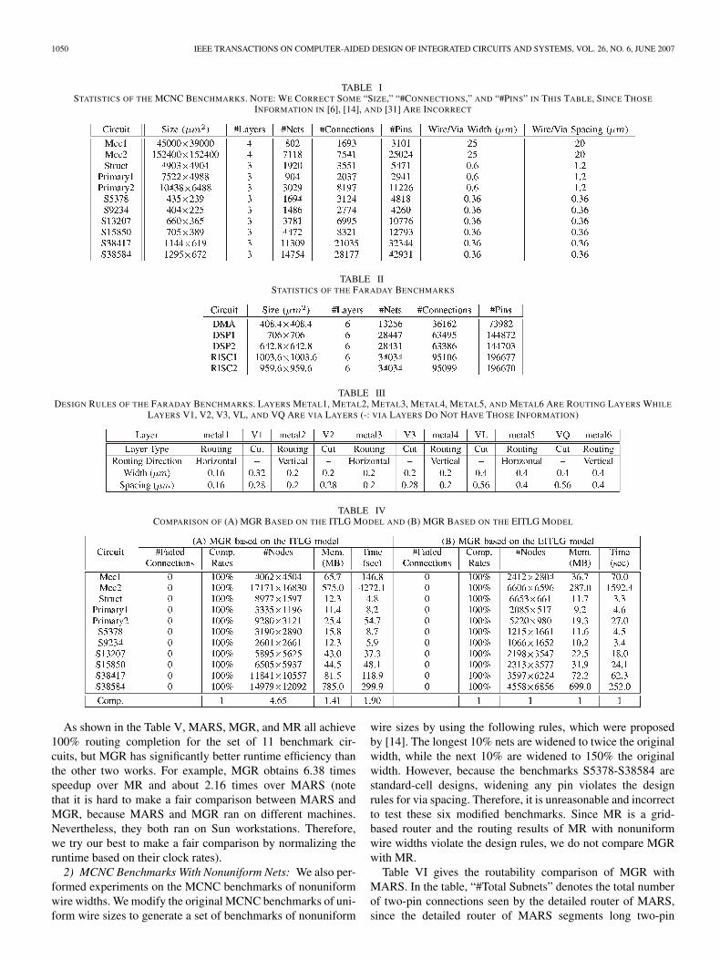
Tables I and II list the set of benchmarks. In these tables,“Circuit” gives the names of the circuits, “Size (µm2)” gives thelayout dimensions in square micrometers, “#Layers” denotesthe number of routing layers used, “#Nets” gives the totalnumber of nets, “#Connections” gives the number of two-pinconnections after net decomposition, “#Pins” gives the numberof pins, “Wire/Via Width (µm)” gives the design rules forwire/via width, and “Wire/Via Spacing (µm)” gives the designrules for wire/via spacing. Table III lists the design rules for theFaraday benchmarks with six metal layers and five via layers,including widths and spacings.
A. Comparison of MGR Based on the ITLG andEITLG Models
Table IV gives the comparison of MGR based on the ITLGand EITLG models. In the table, “#Failed Connections” denotesthe number of failed connections, “Comp. Rates” gives therouting completion rates, “#Nodes” denotes the total numberof nodes, “Mem. (MB)” denotes the storage requirementsin megabytes, and “Time (sec)” represents the runtimes inseconds.
The experimental results show that MGR based on theEITLG model is much more efficient. As shown in the table,MGR based on the EITLG model achieves equal routing solu-tions to MGR based on the ITLG model with 1.90 × runtimespeedup, 4.65 × reduction in the total number of nodes, and1.41 × reduction in the storage requirements.
B. Multilevel Routing With MCNC Benchmarks
1) MCNC Benchmarks With Uniform Nets: Table V com-pares MGR with the multilevel grid-based router with theroutability mode proposed in [6] and [31] (called MR)and the multilevel gridless-routing system (multilevel grid-less global routing + flat gridless detailed routing) in [14](called MARS).
1050 IEEE TRANSACTIONS ON COMPUTER-AIDED DESIGN OF INTEGRATED CIRCUITS AND SYSTEMS, VOL. 26, NO. 6, JUNE 2007
TABLE ISTATISTICS OF THE MCNC BENCHMARKS. NOTE: WE CORRECT SOME “SIZE,” “#CONNECTIONS,” AND “#PINS” IN THIS TABLE, SINCE THOSE
INFORMATION IN [6], [14], AND [31] ARE INCORRECT
TABLE IISTATISTICS OF THE FARADAY BENCHMARKS
TABLE IIIDESIGN RULES OF THE FARADAY BENCHMARKS. LAYERS METAL1, METAL2, METAL3, METAL4, METAL5, AND METAL6 ARE ROUTING LAYERS WHILE
LAYERS V1, V2, V3, VL, AND VQ ARE VIA LAYERS (-: VIA LAYERS DO NOT HAVE THOSE INFORMATION)
TABLE IVCOMPARISON OF (A) MGR BASED ON THE ITLG MODEL AND (B) MGR BASED ON THE EITLG MODEL
As shown in the Table V, MARS, MGR, and MR all achieve100% routing completion for the set of 11 benchmark cir-cuits, but MGR has significantly better runtime efficiency thanthe other two works. For example, MGR obtains 6.38 timesspeedup over MR and about 2.16 times over MARS (notethat it is hard to make a fair comparison between MARS andMGR, because MARS and MGR ran on different machines.Nevertheless, they both ran on Sun workstations. Therefore,we try our best to make a fair comparison by normalizing theruntime based on their clock rates).2) MCNC Benchmarks With Nonuniform Nets: We also per-
formed experiments on the MCNC benchmarks of nonuniformwire widths. We modify the original MCNC benchmarks of uni-form wire sizes to generate a set of benchmarks of nonuniform
wire sizes by using the following rules, which were proposedby [14]. The longest 10% nets are widened to twice the originalwidth, while the next 10% are widened to 150% the originalwidth. However, because the benchmarks S5378-S38584 arestandard-cell designs, widening any pin violates the designrules for via spacing. Therefore, it is unreasonable and incorrectto test these six modified benchmarks. Since MR is a grid-based router and the routing results of MR with nonuniformwire widths violate the design rules, we do not compare MGRwith MR.
Table VI gives the routability comparison of MGR withMARS. In the table, “#Total Subnets” denotes the total numberof two-pin connections seen by the detailed router of MARS,since the detailed router of MARS segments long two-pin
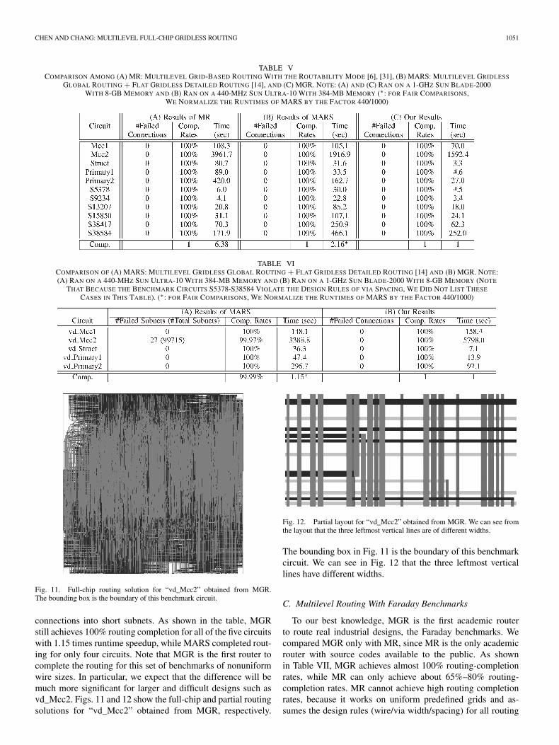
CHEN AND CHANG: MULTILEVEL FULL-CHIP GRIDLESS ROUTING 1051
TABLE VCOMPARISON AMONG (A) MR: MULTILEVEL GRID-BASED ROUTING WITH THE ROUTABILITY MODE [6], [31], (B) MARS: MULTILEVEL GRIDLESS
GLOBAL ROUTING + FLAT GRIDLESS DETAILED ROUTING [14], AND (C) MGR. NOTE: (A) AND (C) RAN ON A 1-GHZ SUN BLADE-2000WITH 8-GB MEMORY AND (B) RAN ON A 440-MHZ SUN ULTRA-10 WITH 384-MB MEMORY (∗: FOR FAIR COMPARISONS,
WE NORMALIZE THE RUNTIMES OF MARS BY THE FACTOR 440/1000)
TABLE VICOMPARISON OF (A) MARS: MULTILEVEL GRIDLESS GLOBAL ROUTING + FLAT GRIDLESS DETAILED ROUTING [14] AND (B) MGR. NOTE:(A) RAN ON A 440-MHZ SUN ULTRA-10 WITH 384-MB MEMORY AND (B) RAN ON A 1-GHZ SUN BLADE-2000 WITH 8-GB MEMORY (NOTE
THAT BECAUSE THE BENCHMARK CIRCUITS S5378-S38584 VIOLATE THE DESIGN RULES OF VIA SPACING, WE DID NOT LIST THESE
CASES IN THIS TABLE). (∗: FOR FAIR COMPARISONS, WE NORMALIZE THE RUNTIMES OF MARS BY THE FACTOR 440/1000)
Fig. 11. Full-chip routing solution for “vd_Mcc2” obtained from MGR.The bounding box is the boundary of this benchmark circuit.
connections into short subnets. As shown in the table, MGRstill achieves 100% routing completion for all of the five circuitswith 1.15 times runtime speedup, while MARS completed rout-ing for only four circuits. Note that MGR is the first router tocomplete the routing for this set of benchmarks of nonuniformwire sizes. In particular, we expect that the difference will bemuch more significant for larger and difficult designs such asvd_Mcc2. Figs. 11 and 12 show the full-chip and partial routingsolutions for “vd_Mcc2” obtained from MGR, respectively.
Fig. 12. Partial layout for “vd_Mcc2” obtained from MGR. We can see fromthe layout that the three leftmost vertical lines are of different widths.
The bounding box in Fig. 11 is the boundary of this benchmarkcircuit. We can see in Fig. 12 that the three leftmost verticallines have different widths.
C. Multilevel Routing With Faraday Benchmarks
To our best knowledge, MGR is the first academic routerto route real industrial designs, the Faraday benchmarks. Wecompared MGR only with MR, since MR is the only academicrouter with source codes available to the public. As shownin Table VII, MGR achieves almost 100% routing-completionrates, while MR can only achieve about 65%–80% routing-completion rates. MR cannot achieve high routing completionrates, because it works on uniform predefined grids and as-sumes the design rules (wire/via width/spacing) for all routing
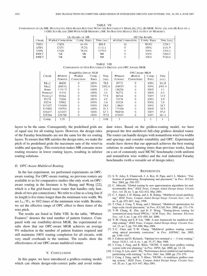
1052 IEEE TRANSACTIONS ON COMPUTER-AIDED DESIGN OF INTEGRATED CIRCUITS AND SYSTEMS, VOL. 26, NO. 6, JUNE 2007
TABLE VIICOMPARISON OF (A) MR: MULTILEVEL GRID-BASED ROUTING WITH THE ROUTABILITY MODE [6], [31], (B) MGR. NOTE: (A) AND (B) RAN ON A
1-GHZ SUN BLADE-2000 WITH 8-GB MEMORY; (NR: NO ROUTING RESULT DUE TO OUT OF MEMORY)
TABLE VIIICOMPARISON OF OUR ROUTABILITY-DRIVEN AND OPC-AWARE MGR
layers to be the same. Consequently, the predefined grids areof equal size for all routing layers. However, the design rulesof the Faraday benchmarks are not the same for the six routinglayers. To ensure that MR satisfies the design rules, we make thepitch of its predefined grids the maximum sum of the wire/viawidths and spacings. This restriction makes MR consume morerouting resource in lower routing layers, resulting in inferiorrouting solutions.
D. OPC-Aware Multilevel Routing
In the last experiment, we performed experiments on OPC-aware routing. For OPC-aware routing, no previous routers areavailable to us for comparative studies (the only work on OPC-aware routing in the literature is by Huang and Wong [22],which is a flat grid-based maze router that handles only hun-dreds of two-pin connections). We refer to a line as a long line ifits length is five times longer than the minimum wire width. Weset LL/WL to 10/2 times of the minimum wire width. Besides,we set the effective range of OPC effect to three times of thewire pitch.
The results are listed in Table VIII. In the table, “#PatternFeatures” denotes the total number of pattern features. Com-pared with our routibility-driven MGR, the experimental re-sults show that our OPC-aware MGR achieves an average9% reduction in the number of pattern features required andstill maintains 100% routing completion for all circuits, withvery small overheads in the runtime. The results show theeffectiveness of our OPC-aware multilevel router.
V. CONCLUSION
In this paper, we have introduced a gridless-routing model,which can obtain design-rule-correct paths and avoid redun-
dant wires. Based on the gridless-routing model, we haveproposed the first multilevel full-chip gridless detailed router.The router can handle designs with nonuniform wire/via widthsand spacings and consider routability and OPC. Experimentalresults have shown that our approach achieves the best routingsolutions in smaller running times than previous works, basedon a set of commonly used MCNC benchmarks (with uniformand nonuniform wire widths) and the real industrial Faradaybenchmarks (with a versatile set of design rules).
REFERENCES
[1] S. N. Adya, S. Chaturvedi, J. A. Roy, D. Papa, and I. L. Markov, “Uni-fication of partitioning, floorplanning and placement,” in Proc. ICCAD,Nov. 2004, pp. 550–557.
[2] C. Albrecht, “Global routing by new approximation algorithms for mul-ticommodity flow,” IEEE Trans. Comput.-Aided Design Integr. CircuitsSyst., vol. 20, no. 5, pp. 622–632, May 2001.
[3] C. J. Alpert, J. H. Huang, and A. B. Kahng, “Multilevel circuit partition-ing,” IEEE Trans. Comput.-Aided Design Integr. Circuits Syst., vol. 17,no. 8, pp. 655–667, Aug. 1998.
[4] T. Chan, J. Cong, T. Kong, and J. Shinnerl, “Multilevel optimization forlarge-scale circuit placement,” in Proc. ICCAD, Nov. 2000, pp. 171–176.
[5] Y.-W. Chang, K. Zhu, and D. F. Wong, “Timing-driven routing forsymmetrical-array-based FPGAs,” ACM Trans. Des. Automat. Electron.Syst., vol. 5, no. 3, pp. 433–450, Jul. 2000.
[6] Y.-W. Chang and S.-P. Lin, “MR: A new framework for multilevel full-chip routing,” IEEE Trans. Comput.-Aided Design Integr. Circuits Syst.,vol. 23, no. 5, pp. 793–800, May 2004.
[7] T.-C. Chen and Y.-W. Chang, “Multilevel gridless routing consid-ering optical proximity correction,” in Proc. ASPDAC, Jan. 2005,pp. 1160–1163.
[8] J. Cohoon and D. Richards, “Optimal two-terminal α − β wire routing,”Integr. VLSI J., vol. 6, no. 1, pp. 35–57, May 1988.
[9] J. Cong, J. Fang, and K. Khoo, “DUNE: A multi-layer gridless routingsystem with wire planning,” in Proc. ISPD, Apr. 2000, pp. 12–18.
[10] J. Cong, S. Lim, and C. Wu, “Performance driven multilevel and multiwaypartitioning with retiming,” in Proc. DAC, Jun. 2000, pp. 274–279.
[11] J. Cong, J. Fang, and K. Y. Khoo, “DUNE—A multilayer gridless rout-ing system,” IEEE Trans. Comput.-Aided Design Integr. Circuits Syst.,vol. 20, no. 5, pp. 633–647, May 2001.
CHEN AND CHANG: MULTILEVEL FULL-CHIP GRIDLESS ROUTING 1053
[12] J. Cong, J. Fang, and Y. Zhang, “Multilevel approach to full-chip gridlessrouting,” in Proc. ICCAD, Nov. 2001, pp. 396–403.
[13] J. Cong, M. Xie, and Y. Zhang, “An enhanced multilevel routing system,”in Proc. ICCAD, Nov. 2002, pp. 51–58.
[14] J. Cong, J. Fang, M. Xie, and Y. Zhang, “MARS—A multilevel full-chipgridless routing system,” IEEE Trans. Comput.-Aided Design Integr. Syst.,vol. 24, no. 3, pp. 382–394, Mar. 2005.
[15] P. Gupta, F. L. Heng, and M. Lavin, “Merits of cellwise model-basedOPC,” in Proc. SPIE, 2004, vol. 5379, pp. 182–189.
[16] M. Hayashi and S. Tsukiyama, “A hybrid hierarchical global router formulti-layer VLSIs,” IEICE Trans. Fundamentals, vol. E78-A, no. 3,pp. 337–344, 1995.
[17] J. Heisterman and T. Lengauer, “The efficient solutions of integerprograms for hierarchical global routing,” IEEE Trans. Comput.-AidedDesign Integr. Circuits Syst., vol. 10, no. 6, pp. 748–753, Jun. 1991.
[18] D. Hightower, “A solution to line routing problems on the continuousplane,” in Proc. Des. Autom. Workshop, 1969, pp. 1–24.
[19] T.-Y. Ho, Y.-W. Chang, S.-J. Chen, and D.-T. Lee, “A fast crosstalk-and performance-driven multilevel routing system,” in Proc. ICCAD,Nov. 2003, pp. 382–387.
[20] T.-Y. Ho, Y.-W. Chang, and S.-J. Chen, “Multilevel routing with antennaavoidance,” in Proc. ISPD, Apr. 2004, pp. 34–40.
[21] T.-Y. Ho, Y.-W. Chang, S.-J. Chen, and D.-T. Lee, “Crosstalk- andperformance-driven multilevel full-chip routing,” IEEE Trans. Comput.-Aided Design Integr. Circuits Syst., vol. 24, no. 6, pp. 869–878, Jun. 2005.
[22] L.-D. Huang and D. F. Wong, “Optical proximity correction (OPC)-friendly maze routing,” in Proc. DAC, Jun. 2004, pp. 186–191.
[23] J. Jaja and S. A. Wu, “On routing two-terminal nets in the presenceof obstacles,” IEEE Trans. Comput.-Aided Design Integr. Circuits Syst.,vol. 8, no. 5, pp. 563–570, May 1989.
[24] A. B. Kahng and Q. Wang, “Implementation and extensibility of ananalytic placer,” in Proc. ISPD, Apr. 2004, pp. 18–25.
[25] A. B. Kahng, S. Reda, and Q. Wang, “APlace: A general analytic place-ment framework,” in Proc. ISPD, Apr. 2005, pp. 233–235.
[26] G. Karypis, R. Aggarwal, V. Kumar, and S. Shekhar, “Multilevel hyper-graph partitioning: Application in VLSI domain,” IEEE Trans. Very LargeScale Integr. (VLSI) Syst., vol. 7, no. 1, pp. 69–79, Mar. 1999.
[27] R. Kastner, E. Bozorgzadeh, and M. Sarrafzadeh, “Predictable routing,”in Proc. ICCAD, Nov. 2000, pp. 110–114.
[28] C. Y. Lee, “An algorithm for path connection and its application,” IRETrans. Electron. Comput., vol. EC-10, no. 3, pp. 346–365, Sep. 1961.
[29] H.-C. Lee, Y.-W. Chang, J.-M. Hsu, and H. Yang, “Multilevel floorplan-ning/placement for large-scale modules using B∗−trees,” in Proc. DAC,Jun. 2003, pp. 812–817.
[30] Y.-L. Lin, Y.-C. Hsu, and F.-S. Tsai, “Hybrid routing,” IEEE Trans.Comput.-Aided Design Integr. Circuits Syst., vol. 9, no. 2, pp. 151–157,Feb. 1990.
[31] S.-P. Lin and Y.-W. Chang, “A novel framework for multilevel routingconsidering routability and performance,” in Proc. ICCAD, Nov. 2002,pp. 44–50.
[32] C. Liu, H.-P. Tseng, and C. Sechen, “Chip-level area routing,” in Proc.ISPD, Apr. 1998, pp. 197–204.
[33] R. Eric Lunow, “A channelless, multilayer router,” in Proc. DAC,Jun. 1988, pp. 667–671.
[34] M. Marek-Sadowska, “Global router for gate array,” in Proc. ICCD,Oct. 1984, pp. 332–337.
[35] M. Marek-Sadowska, “Router planner for custom chip design,” in Proc.ICCAD, Nov. 1986, pp. 246–249.
[36] A. Margarino, A. Romano, A. De Gloria, F. Curatelli, and P. Antognetti,“A tile-expansion router,” IEEE Trans. Comput.-Aided Design Integr.Circuits Syst., vol. CAD-6, no. 4, pp. 507–517, Jul. 1987.
[37] G. Meixner and U. Lauther, “A new global router based on a flow modeland linear assignment,” in Proc. ICCAD, Nov. 1990, pp. 44–47.
[38] T. Ohtsuki, “Gridless routers-new wire routing algorithms based on com-putational geometry,” in Proc. Int. Conf. Circuits and Syst., May 1985,pp. 802–809.
[39] J. K. Ousterhout, “Corner stitching: A data-structure technique for VLSIlayout tools,” IEEE Trans. Comput.-Aided Design Integr. Circuits Syst.,vol. CAD-3, no. 1, pp. 87–100, Jan. 1984.
[40] M. Sato, J. Sakanaka, and T. Ohtsuki, “A fast line-search method basedon a tile plane,” in Proc. IEEE Int. Symp. Circuits and Syst., May 1987,pp. 588–591.
[41] W. Schiele, T. Kruger, K. Just, and F. Kirsch, “A gridless router forindustrial design rules,” in Proc. DAC, Jun. 1990, pp. 626–631.
[42] J. Soukup, “Fast maze router,” in Proc. DAC, Jun. 1978, pp. 100–102.[43] C. Tsai, S. Chen, and W. Feng, “An H-V alternating router,” IEEE Trans.
Comput.-Aided Design Integr. Circuits Syst., vol. 11, no. 8, pp. 976–991,Aug. 1992.
[44] D. Wang and E. Kuh, “A new timing-driven multilayer MCM/IC routingalgorithm,” in Proc. Multi-chip Module Conf., Feb. 1997, pp. 89–94.
[45] Y. F. Wu, P. Widmayer, M. D. F. Schlag, and C. K. Wong, “Rectilinearshortest paths and minimum spanning trees in the presence of rectilin-ear obstacles,” IEEE Trans. Comput., vol. C-36, no. 3, pp. 321–331,Mar. 1987.
[46] Y.-R. Wu, M.-C. Tsai, and T.-C. Wang, “Maze routing with OPC consid-ertion,” in Proc. ASPDAC, Jan. 2005, pp. 198–203.
[47] Z. Xing and R. Kaog, “Shortest path search using tiles and piecewise lin-ear cost propagation,” IEEE Trans. Comput.-Aided Design Integr. CircuitsSyst., vol. 21, no. 2, pp. 145–158, Feb. 2002.
[48] S. Q. Zheng, J. S. Lim, and S. S. Iyengar, “Finding obstacle-avoidingshortest paths using implicit connection graphs,” IEEE Trans. Comput.-Aided Design Integr. Circuits Syst., vol. 15, no. 1, pp. 103–110, Jan. 1996.
Tai-Chen Chen (S’02) received the B.S. and M.S.degrees in computer and information science fromNational Chiao Tung University, Hsinchu, Taiwan, in1999 and 2001, respectively. He is currently workingtoward the Ph.D. degree in the Graduate Instituteof Electronics Engineering, National Taiwan Univer-sity, Taipei, Taiwan.
His current research interests include computer-aided design and gridless routing for nanometer elec-trical effects.
Mr. Chen is the recipient of the Best M.S. ThesisAward from the National Science Council of Taiwan in 2002.
Yao-Wen Chang (S’94–M’96) received the B.S.degree from the National Taiwan University, Taipei,Taiwan, in 1988 and the M.S. and Ph.D. degrees fromthe University of Texas at Austin in 1993 and 1996,respectively, all in computer science.
He is a Professor in the Department of ElectricalEngineering and the Graduate Institute of Electron-ics Engineering, National Taiwan University. He iscurrently also a Visiting Professor at Waseda Uni-versity, Kitakyushu, Japan. He was with the IBM T.J.Watson Research Center, Yorktown Heights, NY, in
the summer of 1994. From 1996 to 2001, he was on the faculty of the NationalChiao Tung University, Hsinchu, Taiwan. He has coauthored more than 110ACM/IEEE conference/journal papers and one book on routing. His currentresearch interests are in VLSI physical design, design for manufacturing, andFPGA. He has been working closely with industry on projects in these areas.He is an Editor of the Journal of Computer and Information Science.
Dr. Chang is currently the Chair of the Design Automation and Test (DAT)Consortium of the Ministry of Education, Taiwan, a member of the Board ofGovernors of Taiwan IC Design Society, and a member of the IEEE Circuitsand Systems Society, ACM, and ACM/SIGDA. He currently serves on theACM/SIGDA Physical Design Technical Committee and the technical programcommittees of important conferences on VLSI design automation, includingASP-DAC (Topic Chair), DAC, DATE, FPT, GLSVLSI, ICCAD, ICCD, ISPD,SOCC (Topic Chair), and VLSI-DAT (Topic Chair). He was a recipient of the2006 ACM ISPD Placement Contest Award, Best Paper Award at ICCD-1995,and eight Best Paper Nominations from DAC-2007, ISPD-2007, DAC-2005,2004 ACM TODAES, ASP-DAC-2003, ICCAD-2002, ICCD-2001, and DAC-2000. He was also a recipient of many awards for research performance, suchas the 2005 and 2006 First-Class Principal Investigator Awards and the 2004Mr. Wu Ta You Memorial Award from National Science Council of Taiwan,the 2004 MXIC Young Chair Professorship from the MXIC Corporation, andfor excellent teaching from the National Taiwan University and National ChiaoTung University.