multicore navigator user guide -...
TRANSCRIPT

KeyStone Architecture
Literature Number: SPRUGR9D+++January 2012
Multicore Navigator
User Guide
ø-ii KeyStone Architecture Multicore Navigator User Guide SPRUGR9D+++—January 2012
www.ti.com
Submit Documentation Feedback TI Confidential—NDA Restrictions
Release History
Release Date Description/Comments
D+++ January 2012 • Added Navigator Cloud note to Rx Flows. (Page 4-23)• Updated QMn Base Address Regs (Page 4-19)• Updated queue numbers (Page 5-3)• Updated queue qpend mapping (Page 5-8)
D++ January 2012 • Added Keystone2 clarifications for programming memory regions. (Page 4-7)• Added Keystone2 notes for QMn Base Address Regs (Page 4-19)• Added Keystone2 queue map (Page 5-3)• Added Keystone2 value for Linking RAM 0 Base Address Reg (Page 4-4)• Added Keystone2 value for Linking RAM 0 Size Reg (Page 4-4)• Added new Diversion Queue command to Accumulator firmware description. (Page 4-38)• Correct BCP PktDMA addresses for Keystone2 (Page 5-12)• Update QoS Cluster Record (Page 4-44)• Updated QMSS INTD interrupt mappings for Keystone 2. (Page 5-8)
D+ October 2011 • Added mapping tables for TCI663x (Page 5-3)• Added descriptions of KeyStone 2 QMSS in Intro chapter (Page 1-3)
D September 2011 • Added section for RR-Mode QoS Cluster (Page 4-45)• Updated Destination Congestion Table 4-56 (Page 4-41)• Added clarification to RX_SIZE_THRESH_EN in Table 4-40. (Page 4-27)• Corrected source tag bits in Table 4-40. (Page 4-26)• New section describing endian translations between an ARM and the device. (Page 2-11)• Reworked sections 5.1 and 5.2 to clarify the differences between devices. (Page 5-2)• Updated Table 4-45. (Page 4-32)• Generalized the Features list. (Page 1-5)• Generalized the Features list. (Page 1-3)• Table 3-23, corrected Dest Tag low bits (Page 3-11)• Table 3-2, corrected Dest Tag low bits (Page 3-3)
C April 2011 • Added VBUSM queue management address to table 5-10. (Page 5-9)• Added clarification to Rx Flow Reg D. (Page 4-28)• Added note in 4.3.1.3 to explain physical queue mapping with PDSP firmware. (Page 4-38)• Added note on memory region/descriptor alignment. (Page 4-7)• Corrected FFTC_C addresses in table 5-11. (Page 5-9)• Corrected FFTC_C addresses in table 5-11. (Page 5-10)• Updated PDSP description (Page 1-8)• Updated Reg C/Reg D notes for VBUSM and Queue Proxy. (Page 4-11)• Updated Rx error handling field note for Rx Flow Reg A. (Page 4-24)
B February 2011 • Added cautionary note when transferring from one L2 to another L2. (Page 4-12)• Added note for AIF monolithic mode and automatic transfers. (Page 4-21)• Added note in Queue Mapping Table. (Page 5-2)• New QoS section. (Page 4-38)• Reorganized the PDSP section to include a new section on the QoS firmware. (Page 4-34)• Updated utility functions in Appendix A. (Page A-1)
A December 2010 • Added clarification note on Registers A, B, C, and D and regions. (Page 4-9)• Added clarification note on Registers A, B, C, and D reads and writes. (Page 4-9)• Added clarification note. (Page 4-12)• Added clarification note. (Page 4-11)• Added new accumulator command to table. (Page 4-36)• Added new section to describe Reclamation Queue processing/setup. (Page 4-38)
SPRUGR9 November 2010 Initial release

Contents
SPRUGR9D+++—January 2012 KeyStone Architecture Multicore Navigator User Guide ø-iiiSubmit Documentation Feedback TI Confidential—NDA Restrictions
www.ti.com
Contents
Release History. . . . . . . . . . . . . . . . . . . . . . . . . . . . . . . . . . . . . . . . . . . . . . . . . . . . . . . . . . . . . . . . . . . . . . . . . . . . . . . . . . . . . . . . . . . . . . . . . . . . . . . ø-iiList of Tables . . . . . . . . . . . . . . . . . . . . . . . . . . . . . . . . . . . . . . . . . . . . . . . . . . . . . . . . . . . . . . . . . . . . . . . . . . . . . . . . . . . . . . . . . . . . . . . . . . . . . . . . ø-viiList of Figures . . . . . . . . . . . . . . . . . . . . . . . . . . . . . . . . . . . . . . . . . . . . . . . . . . . . . . . . . . . . . . . . . . . . . . . . . . . . . . . . . . . . . . . . . . . . . . . . . . . . . . . . .ø-x
Preface ø-xiiiAbout This Manual . . . . . . . . . . . . . . . . . . . . . . . . . . . . . . . . . . . . . . . . . . . . . . . . . . . . . . . . . . . . . . . . . . . . . . . . . . . . . . . ø-xiiiNotational Conventions . . . . . . . . . . . . . . . . . . . . . . . . . . . . . . . . . . . . . . . . . . . . . . . . . . . . . . . . . . . . . . . . . . . . . . . . . . ø-xiiiRelated Documentation from Texas Instruments . . . . . . . . . . . . . . . . . . . . . . . . . . . . . . . . . . . . . . . . . . . . . . . . . . ø-xivTrademarks . . . . . . . . . . . . . . . . . . . . . . . . . . . . . . . . . . . . . . . . . . . . . . . . . . . . . . . . . . . . . . . . . . . . . . . . . . . . . . . . . . . . . . ø-xiv
Chapter 1
Introduction 1-11.1 Terminology Used in This Document . . . . . . . . . . . . . . . . . . . . . . . . . . . . . . . . . . . . . . . . . . . . . . . . . . . . . . . . . . . 1-21.2 KeyStone 1 Features . . . . . . . . . . . . . . . . . . . . . . . . . . . . . . . . . . . . . . . . . . . . . . . . . . . . . . . . . . . . . . . . . . . . . . . . . . . 1-31.3 KeyStone 1 Functional Block Diagram . . . . . . . . . . . . . . . . . . . . . . . . . . . . . . . . . . . . . . . . . . . . . . . . . . . . . . . . . . 1-41.4 KeyStone 2 Changes to QMSS . . . . . . . . . . . . . . . . . . . . . . . . . . . . . . . . . . . . . . . . . . . . . . . . . . . . . . . . . . . . . . . . . . 1-51.5 KeyStone 2 QMSS Modes of Use . . . . . . . . . . . . . . . . . . . . . . . . . . . . . . . . . . . . . . . . . . . . . . . . . . . . . . . . . . . . . . . . 1-6
1.5.1 Shared Mode . . . . . . . . . . . . . . . . . . . . . . . . . . . . . . . . . . . . . . . . . . . . . . . . . . . . . . . . . . . . . . . . . . . . . . . . . . . . . . . . . . . . . . . 1-61.5.2 Split Mode . . . . . . . . . . . . . . . . . . . . . . . . . . . . . . . . . . . . . . . . . . . . . . . . . . . . . . . . . . . . . . . . . . . . . . . . . . . . . . . . . . . . . . . . . . 1-6
1.6 Overview . . . . . . . . . . . . . . . . . . . . . . . . . . . . . . . . . . . . . . . . . . . . . . . . . . . . . . . . . . . . . . . . . . . . . . . . . . . . . . . . . . . . . . 1-71.7 Queue Manager . . . . . . . . . . . . . . . . . . . . . . . . . . . . . . . . . . . . . . . . . . . . . . . . . . . . . . . . . . . . . . . . . . . . . . . . . . . . . . . 1-71.8 Packet DMA (PKTDMA) . . . . . . . . . . . . . . . . . . . . . . . . . . . . . . . . . . . . . . . . . . . . . . . . . . . . . . . . . . . . . . . . . . . . . . . . . 1-71.9 Navigator Cloud . . . . . . . . . . . . . . . . . . . . . . . . . . . . . . . . . . . . . . . . . . . . . . . . . . . . . . . . . . . . . . . . . . . . . . . . . . . . . . . 1-71.10 PDSP Firmware . . . . . . . . . . . . . . . . . . . . . . . . . . . . . . . . . . . . . . . . . . . . . . . . . . . . . . . . . . . . . . . . . . . . . . . . . . . . . . . 1-8
Chapter 2
Operational Concepts 2-12.1 Packets . . . . . . . . . . . . . . . . . . . . . . . . . . . . . . . . . . . . . . . . . . . . . . . . . . . . . . . . . . . . . . . . . . . . . . . . . . . . . . . . . . . . . . . . 2-22.2 Queues . . . . . . . . . . . . . . . . . . . . . . . . . . . . . . . . . . . . . . . . . . . . . . . . . . . . . . . . . . . . . . . . . . . . . . . . . . . . . . . . . . . . . . . . 2-2
2.2.1 Packet Queuing . . . . . . . . . . . . . . . . . . . . . . . . . . . . . . . . . . . . . . . . . . . . . . . . . . . . . . . . . . . . . . . . . . . . . . . . . . . . . . . . . . . . . 2-22.2.2 Packet De-queuing. . . . . . . . . . . . . . . . . . . . . . . . . . . . . . . . . . . . . . . . . . . . . . . . . . . . . . . . . . . . . . . . . . . . . . . . . . . . . . . . . . 2-22.2.3 Queue Proxy . . . . . . . . . . . . . . . . . . . . . . . . . . . . . . . . . . . . . . . . . . . . . . . . . . . . . . . . . . . . . . . . . . . . . . . . . . . . . . . . . . . . . . . . 2-2
2.3 Queue Types . . . . . . . . . . . . . . . . . . . . . . . . . . . . . . . . . . . . . . . . . . . . . . . . . . . . . . . . . . . . . . . . . . . . . . . . . . . . . . . . . . 2-32.3.1 Transmit Queues. . . . . . . . . . . . . . . . . . . . . . . . . . . . . . . . . . . . . . . . . . . . . . . . . . . . . . . . . . . . . . . . . . . . . . . . . . . . . . . . . . . . 2-32.3.2 Transmit Completion Queues . . . . . . . . . . . . . . . . . . . . . . . . . . . . . . . . . . . . . . . . . . . . . . . . . . . . . . . . . . . . . . . . . . . . . . . 2-32.3.3 Receive Queues . . . . . . . . . . . . . . . . . . . . . . . . . . . . . . . . . . . . . . . . . . . . . . . . . . . . . . . . . . . . . . . . . . . . . . . . . . . . . . . . . . . . . 2-32.3.4 Free Descriptor Queues (FDQ) . . . . . . . . . . . . . . . . . . . . . . . . . . . . . . . . . . . . . . . . . . . . . . . . . . . . . . . . . . . . . . . . . . . . . . . 2-3
2.3.4.1 Host Packet Free Descriptors . . . . . . . . . . . . . . . . . . . . . . . . . . . . . . . . . . . . . . . . . . . . . . . . . . . . . . . . . . . . . . . . . . 2-32.3.4.2 Monolithic Free Descriptors. . . . . . . . . . . . . . . . . . . . . . . . . . . . . . . . . . . . . . . . . . . . . . . . . . . . . . . . . . . . . . . . . . . 2-3
2.4 Descriptors . . . . . . . . . . . . . . . . . . . . . . . . . . . . . . . . . . . . . . . . . . . . . . . . . . . . . . . . . . . . . . . . . . . . . . . . . . . . . . . . . . . . 2-42.4.1 Host Packet . . . . . . . . . . . . . . . . . . . . . . . . . . . . . . . . . . . . . . . . . . . . . . . . . . . . . . . . . . . . . . . . . . . . . . . . . . . . . . . . . . . . . . . . . 2-42.4.2 Host Buffer. . . . . . . . . . . . . . . . . . . . . . . . . . . . . . . . . . . . . . . . . . . . . . . . . . . . . . . . . . . . . . . . . . . . . . . . . . . . . . . . . . . . . . . . . . 2-42.4.3 Monolithic Packet . . . . . . . . . . . . . . . . . . . . . . . . . . . . . . . . . . . . . . . . . . . . . . . . . . . . . . . . . . . . . . . . . . . . . . . . . . . . . . . . . . . 2-4
2.5 Packet DMA . . . . . . . . . . . . . . . . . . . . . . . . . . . . . . . . . . . . . . . . . . . . . . . . . . . . . . . . . . . . . . . . . . . . . . . . . . . . . . . . . . . 2-62.5.1 Channels . . . . . . . . . . . . . . . . . . . . . . . . . . . . . . . . . . . . . . . . . . . . . . . . . . . . . . . . . . . . . . . . . . . . . . . . . . . . . . . . . . . . . . . . . . . 2-62.5.2 Rx Flows . . . . . . . . . . . . . . . . . . . . . . . . . . . . . . . . . . . . . . . . . . . . . . . . . . . . . . . . . . . . . . . . . . . . . . . . . . . . . . . . . . . . . . . . . . . . 2-6
2.6 Packet Transmission Overview . . . . . . . . . . . . . . . . . . . . . . . . . . . . . . . . . . . . . . . . . . . . . . . . . . . . . . . . . . . . . . . . . 2-72.7 Packet Reception Overview . . . . . . . . . . . . . . . . . . . . . . . . . . . . . . . . . . . . . . . . . . . . . . . . . . . . . . . . . . . . . . . . . . . . 2-92.8 ARM Endianess . . . . . . . . . . . . . . . . . . . . . . . . . . . . . . . . . . . . . . . . . . . . . . . . . . . . . . . . . . . . . . . . . . . . . . . . . . . . . . .2-11

Contents
ø-iv KeyStone Architecture Multicore Navigator User Guide SPRUGR9D+++—January 2012Submit Documentation Feedback TI Confidential—NDA Restrictions
www.ti.com
Chapter 3
Descriptor Layouts 3-13.1 Host Packet Descriptor . . . . . . . . . . . . . . . . . . . . . . . . . . . . . . . . . . . . . . . . . . . . . . . . . . . . . . . . . . . . . . . . . . . . . . . . . 3-23.2 Host Buffer Descriptor . . . . . . . . . . . . . . . . . . . . . . . . . . . . . . . . . . . . . . . . . . . . . . . . . . . . . . . . . . . . . . . . . . . . . . . . . 3-73.3 Monolithic Descriptor . . . . . . . . . . . . . . . . . . . . . . . . . . . . . . . . . . . . . . . . . . . . . . . . . . . . . . . . . . . . . . . . . . . . . . . . .3-10
Chapter 4
Registers 4-14.1 Queue Manager . . . . . . . . . . . . . . . . . . . . . . . . . . . . . . . . . . . . . . . . . . . . . . . . . . . . . . . . . . . . . . . . . . . . . . . . . . . . . . . 4-2
4.1.1 Queue Configuration Region . . . . . . . . . . . . . . . . . . . . . . . . . . . . . . . . . . . . . . . . . . . . . . . . . . . . . . . . . . . . . . . . . . . . . . . . 4-24.1.1.1 Revision Register (0x00000000) . . . . . . . . . . . . . . . . . . . . . . . . . . . . . . . . . . . . . . . . . . . . . . . . . . . . . . . . . . . . . . . 4-34.1.1.2 Queue Diversion Register (0x00000008) . . . . . . . . . . . . . . . . . . . . . . . . . . . . . . . . . . . . . . . . . . . . . . . . . . . . . . . 4-34.1.1.3 Linking RAM Region 0 Base Address Register (0x0000000C) . . . . . . . . . . . . . . . . . . . . . . . . . . . . . . . . . . . . 4-44.1.1.4 Linking RAM Region 0 Size Register (0x00000010) . . . . . . . . . . . . . . . . . . . . . . . . . . . . . . . . . . . . . . . . . . . . . 4-44.1.1.5 Linking RAM Region 1 Base Address Register (0x00000014) . . . . . . . . . . . . . . . . . . . . . . . . . . . . . . . . . . . . 4-54.1.1.6 Free Descriptor/Buffer Starvation Count Register N (0x00000020 + N×4) . . . . . . . . . . . . . . . . . . . . . . . 4-5
4.1.2 Queue Status RAM . . . . . . . . . . . . . . . . . . . . . . . . . . . . . . . . . . . . . . . . . . . . . . . . . . . . . . . . . . . . . . . . . . . . . . . . . . . . . . . . . . 4-64.1.3 Descriptor Memory Setup Region. . . . . . . . . . . . . . . . . . . . . . . . . . . . . . . . . . . . . . . . . . . . . . . . . . . . . . . . . . . . . . . . . . . . 4-7
4.1.3.1 Memory Region R Base Address Register (0x00000000 + 16×R). . . . . . . . . . . . . . . . . . . . . . . . . . . . . . . . . 4-74.1.3.2 Memory Region R Start Index Register (0x00000004 + 16×R) . . . . . . . . . . . . . . . . . . . . . . . . . . . . . . . . . . . 4-84.1.3.3 Memory Region R Descriptor Setup Register (0x00000008 + 16×R) . . . . . . . . . . . . . . . . . . . . . . . . . . . . . 4-8
4.1.4 Queue Management/Queue Proxy Regions . . . . . . . . . . . . . . . . . . . . . . . . . . . . . . . . . . . . . . . . . . . . . . . . . . . . . . . . . . 4-94.1.4.1 Queue N Register A (0x00000000 + 16×N) . . . . . . . . . . . . . . . . . . . . . . . . . . . . . . . . . . . . . . . . . . . . . . . . . . . .4-104.1.4.2 Queue N Register B (0x00000004 + 16×N) . . . . . . . . . . . . . . . . . . . . . . . . . . . . . . . . . . . . . . . . . . . . . . . . . . . .4-104.1.4.3 Queue N Register C (0x00000008 + 16×N) . . . . . . . . . . . . . . . . . . . . . . . . . . . . . . . . . . . . . . . . . . . . . . . . . . . .4-114.1.4.4 Queue N Register D (0x0000000C + 16×N). . . . . . . . . . . . . . . . . . . . . . . . . . . . . . . . . . . . . . . . . . . . . . . . . . . .4-12
4.1.5 Queue Peek Region . . . . . . . . . . . . . . . . . . . . . . . . . . . . . . . . . . . . . . . . . . . . . . . . . . . . . . . . . . . . . . . . . . . . . . . . . . . . . . . .4-134.1.5.1 Queue N Status and Configuration Register A (0x00000000 + 16×N). . . . . . . . . . . . . . . . . . . . . . . . . . .4-134.1.5.2 Queue N Status and Configuration Register B (0x00000004 + 16×N) . . . . . . . . . . . . . . . . . . . . . . . . . . .4-144.1.5.3 Queue N Status and Configuration Register C (0x00000008 + 16×N). . . . . . . . . . . . . . . . . . . . . . . . . . .4-144.1.5.4 Queue N Status and Configuration Register D (0x0000000C + 16×N) . . . . . . . . . . . . . . . . . . . . . . . . . .4-15
4.2 Packet DMA . . . . . . . . . . . . . . . . . . . . . . . . . . . . . . . . . . . . . . . . . . . . . . . . . . . . . . . . . . . . . . . . . . . . . . . . . . . . . . . . . .4-164.2.1 Global Control Registers Region . . . . . . . . . . . . . . . . . . . . . . . . . . . . . . . . . . . . . . . . . . . . . . . . . . . . . . . . . . . . . . . . . . . .4-16
4.2.1.1 Revision Register (0x00). . . . . . . . . . . . . . . . . . . . . . . . . . . . . . . . . . . . . . . . . . . . . . . . . . . . . . . . . . . . . . . . . . . . . .4-174.2.1.2 Performance Control Register (0x04) . . . . . . . . . . . . . . . . . . . . . . . . . . . . . . . . . . . . . . . . . . . . . . . . . . . . . . . . .4-174.2.1.3 Emulation Control Register (0x08). . . . . . . . . . . . . . . . . . . . . . . . . . . . . . . . . . . . . . . . . . . . . . . . . . . . . . . . . . . .4-184.2.1.4 Priority Control Register (0x0C). . . . . . . . . . . . . . . . . . . . . . . . . . . . . . . . . . . . . . . . . . . . . . . . . . . . . . . . . . . . . . .4-184.2.1.5 QMn Base Address Register (0x10, 0x14, 0x18, 0x1c) . . . . . . . . . . . . . . . . . . . . . . . . . . . . . . . . . . . . . . . . . .4-19
4.2.2 Tx DMA Channel Configuration Region . . . . . . . . . . . . . . . . . . . . . . . . . . . . . . . . . . . . . . . . . . . . . . . . . . . . . . . . . . . . .4-204.2.2.1 Tx Channel N Global Configuration Register A (0x000 + 32×N) . . . . . . . . . . . . . . . . . . . . . . . . . . . . . . . .4-204.2.2.2 Tx Channel N Global Configuration Register B (0x004 + 32×N) . . . . . . . . . . . . . . . . . . . . . . . . . . . . . . . .4-21
4.2.3 Rx DMA Channel Configuration Region . . . . . . . . . . . . . . . . . . . . . . . . . . . . . . . . . . . . . . . . . . . . . . . . . . . . . . . . . . . . .4-224.2.3.1 Rx Channel N Global Configuration Register A (0x000 + 32×N) . . . . . . . . . . . . . . . . . . . . . . . . . . . . . . . .4-22
4.2.4 Rx DMA Flow Configuration Region. . . . . . . . . . . . . . . . . . . . . . . . . . . . . . . . . . . . . . . . . . . . . . . . . . . . . . . . . . . . . . . . .4-234.2.4.1 Rx Flow N Configuration Register A (0x000 + 32×N). . . . . . . . . . . . . . . . . . . . . . . . . . . . . . . . . . . . . . . . . . .4-234.2.4.2 Rx Flow N Configuration Register B (0x004 + 32×N) . . . . . . . . . . . . . . . . . . . . . . . . . . . . . . . . . . . . . . . . . . .4-254.2.4.3 Rx Flow N Configuration Register C (0x008 + 32×N) . . . . . . . . . . . . . . . . . . . . . . . . . . . . . . . . . . . . . . . . . . .4-264.2.4.4 Rx Flow N Configuration Register D (0x00C + 32×N) . . . . . . . . . . . . . . . . . . . . . . . . . . . . . . . . . . . . . . . . . .4-284.2.4.5 Rx Flow N Configuration Register E (0x010 + 32×N) . . . . . . . . . . . . . . . . . . . . . . . . . . . . . . . . . . . . . . . . . . .4-294.2.4.6 Rx Flow N Configuration Register F (0x014 + 32×N) . . . . . . . . . . . . . . . . . . . . . . . . . . . . . . . . . . . . . . . . . . .4-304.2.4.7 Rx Flow N Configuration Register G (0x018 + 32×N). . . . . . . . . . . . . . . . . . . . . . . . . . . . . . . . . . . . . . . . . . .4-314.2.4.8 Rx Flow N Configuration Register H (0x01C + 32×N) . . . . . . . . . . . . . . . . . . . . . . . . . . . . . . . . . . . . . . . . . .4-32
4.2.5 Tx Scheduler Configuration Region . . . . . . . . . . . . . . . . . . . . . . . . . . . . . . . . . . . . . . . . . . . . . . . . . . . . . . . . . . . . . . . . .4-334.2.5.1 Tx Channel N Scheduler Configuration Register (0x000 + 4×N) . . . . . . . . . . . . . . . . . . . . . . . . . . . . . . . .4-33
4.3 QMSS PDSPs . . . . . . . . . . . . . . . . . . . . . . . . . . . . . . . . . . . . . . . . . . . . . . . . . . . . . . . . . . . . . . . . . . . . . . . . . . . . . . . . . .4-344.3.1 Descriptor Accumulation Firmware . . . . . . . . . . . . . . . . . . . . . . . . . . . . . . . . . . . . . . . . . . . . . . . . . . . . . . . . . . . . . . . . .4-35

Contents
SPRUGR9D+++—January 2012 KeyStone Architecture Multicore Navigator User Guide ø-vSubmit Documentation Feedback TI Confidential—NDA Restrictions
www.ti.com
4.3.1.1 Command Buffer Interface . . . . . . . . . . . . . . . . . . . . . . . . . . . . . . . . . . . . . . . . . . . . . . . . . . . . . . . . . . . . . . . . . . .4-354.3.1.2 Global Timer Command Interface . . . . . . . . . . . . . . . . . . . . . . . . . . . . . . . . . . . . . . . . . . . . . . . . . . . . . . . . . . . .4-374.3.1.3 Reclamation Queue Command Interface . . . . . . . . . . . . . . . . . . . . . . . . . . . . . . . . . . . . . . . . . . . . . . . . . . . . .4-384.3.1.4 Queue Diversion Command Interface . . . . . . . . . . . . . . . . . . . . . . . . . . . . . . . . . . . . . . . . . . . . . . . . . . . . . . . .4-38
4.3.2 Quality of Service Firmware . . . . . . . . . . . . . . . . . . . . . . . . . . . . . . . . . . . . . . . . . . . . . . . . . . . . . . . . . . . . . . . . . . . . . . . .4-394.3.2.1 QoS Algorithms . . . . . . . . . . . . . . . . . . . . . . . . . . . . . . . . . . . . . . . . . . . . . . . . . . . . . . . . . . . . . . . . . . . . . . . . . . . . .4-394.3.2.2 Command Buffer Interface . . . . . . . . . . . . . . . . . . . . . . . . . . . . . . . . . . . . . . . . . . . . . . . . . . . . . . . . . . . . . . . . . . .4-424.3.2.3 QoS Firmware Commands . . . . . . . . . . . . . . . . . . . . . . . . . . . . . . . . . . . . . . . . . . . . . . . . . . . . . . . . . . . . . . . . . . .4-434.3.2.4 QoS Queue Record . . . . . . . . . . . . . . . . . . . . . . . . . . . . . . . . . . . . . . . . . . . . . . . . . . . . . . . . . . . . . . . . . . . . . . . . . .4-444.3.2.5 QoS Cluster Record . . . . . . . . . . . . . . . . . . . . . . . . . . . . . . . . . . . . . . . . . . . . . . . . . . . . . . . . . . . . . . . . . . . . . . . . . .4-444.3.2.6 RR-Mode QoS Cluster Record . . . . . . . . . . . . . . . . . . . . . . . . . . . . . . . . . . . . . . . . . . . . . . . . . . . . . . . . . . . . . . . .4-45
4.3.3 Navigator Runtime Firmware . . . . . . . . . . . . . . . . . . . . . . . . . . . . . . . . . . . . . . . . . . . . . . . . . . . . . . . . . . . . . . . . . . . . . . .4-474.3.4 Interrupt Operation . . . . . . . . . . . . . . . . . . . . . . . . . . . . . . . . . . . . . . . . . . . . . . . . . . . . . . . . . . . . . . . . . . . . . . . . . . . . . . . .4-47
4.3.4.1 Interrupt Handshaking. . . . . . . . . . . . . . . . . . . . . . . . . . . . . . . . . . . . . . . . . . . . . . . . . . . . . . . . . . . . . . . . . . . . . . .4-474.3.4.2 Interrupt Processing . . . . . . . . . . . . . . . . . . . . . . . . . . . . . . . . . . . . . . . . . . . . . . . . . . . . . . . . . . . . . . . . . . . . . . . . .4-484.3.4.3 Interrupt Generation. . . . . . . . . . . . . . . . . . . . . . . . . . . . . . . . . . . . . . . . . . . . . . . . . . . . . . . . . . . . . . . . . . . . . . . . .4-484.3.4.4 Stall Avoidance . . . . . . . . . . . . . . . . . . . . . . . . . . . . . . . . . . . . . . . . . . . . . . . . . . . . . . . . . . . . . . . . . . . . . . . . . . . . . .4-49
4.3.5 QMSS PDSP Registers . . . . . . . . . . . . . . . . . . . . . . . . . . . . . . . . . . . . . . . . . . . . . . . . . . . . . . . . . . . . . . . . . . . . . . . . . . . . . .4-494.3.5.1 Control Register (0x00000000) . . . . . . . . . . . . . . . . . . . . . . . . . . . . . . . . . . . . . . . . . . . . . . . . . . . . . . . . . . . . . . .4-504.3.5.2 Status Register (0x00000004) . . . . . . . . . . . . . . . . . . . . . . . . . . . . . . . . . . . . . . . . . . . . . . . . . . . . . . . . . . . . . . . .4-514.3.5.3 Cycle Count Register (0x0000000C) . . . . . . . . . . . . . . . . . . . . . . . . . . . . . . . . . . . . . . . . . . . . . . . . . . . . . . . . . .4-514.3.5.4 Stall Count Register (0x00000010). . . . . . . . . . . . . . . . . . . . . . . . . . . . . . . . . . . . . . . . . . . . . . . . . . . . . . . . . . . .4-52
4.4 QMSS Interrupt Distributor . . . . . . . . . . . . . . . . . . . . . . . . . . . . . . . . . . . . . . . . . . . . . . . . . . . . . . . . . . . . . . . . . . . .4-534.4.1 INTD Register Region. . . . . . . . . . . . . . . . . . . . . . . . . . . . . . . . . . . . . . . . . . . . . . . . . . . . . . . . . . . . . . . . . . . . . . . . . . . . . . .4-53
4.4.1.1 Revision Register (0x00000000) . . . . . . . . . . . . . . . . . . . . . . . . . . . . . . . . . . . . . . . . . . . . . . . . . . . . . . . . . . . . . .4-544.4.1.2 End Of Interrupt (EOI) Register (0x00000010) . . . . . . . . . . . . . . . . . . . . . . . . . . . . . . . . . . . . . . . . . . . . . . . . .4-544.4.1.3 Status Register 0 (0x00000200). . . . . . . . . . . . . . . . . . . . . . . . . . . . . . . . . . . . . . . . . . . . . . . . . . . . . . . . . . . . . . .4-554.4.1.4 Status Register 1 (0x00000204). . . . . . . . . . . . . . . . . . . . . . . . . . . . . . . . . . . . . . . . . . . . . . . . . . . . . . . . . . . . . . .4-554.4.1.5 Status Register 4 (0x00000210). . . . . . . . . . . . . . . . . . . . . . . . . . . . . . . . . . . . . . . . . . . . . . . . . . . . . . . . . . . . . . .4-564.4.1.6 Status Clear Register 0 (0x00000280) . . . . . . . . . . . . . . . . . . . . . . . . . . . . . . . . . . . . . . . . . . . . . . . . . . . . . . . . .4-564.4.1.7 Status Clear Register 1 (0x00000284) . . . . . . . . . . . . . . . . . . . . . . . . . . . . . . . . . . . . . . . . . . . . . . . . . . . . . . . . .4-574.4.1.8 Status Clear Register 4 (0x00000290) . . . . . . . . . . . . . . . . . . . . . . . . . . . . . . . . . . . . . . . . . . . . . . . . . . . . . . . . .4-584.4.1.9 Interrupt N Count Register (0x00000300 + 4xN). . . . . . . . . . . . . . . . . . . . . . . . . . . . . . . . . . . . . . . . . . . . . . .4-59
Chapter 5
Mapping Information 5-15.1 Queue Maps . . . . . . . . . . . . . . . . . . . . . . . . . . . . . . . . . . . . . . . . . . . . . . . . . . . . . . . . . . . . . . . . . . . . . . . . . . . . . . . . . . . 5-25.2 Interrupt Maps. . . . . . . . . . . . . . . . . . . . . . . . . . . . . . . . . . . . . . . . . . . . . . . . . . . . . . . . . . . . . . . . . . . . . . . . . . . . . . . . . 5-4
5.2.1 KeyStone 1 TCI661x, C6670 devices . . . . . . . . . . . . . . . . . . . . . . . . . . . . . . . . . . . . . . . . . . . . . . . . . . . . . . . . . . . . . . . . . . 5-45.2.2 KeyStone 1 TCI660x, C667x devices . . . . . . . . . . . . . . . . . . . . . . . . . . . . . . . . . . . . . . . . . . . . . . . . . . . . . . . . . . . . . . . . . . 5-65.2.3 KeyStone 2 devices . . . . . . . . . . . . . . . . . . . . . . . . . . . . . . . . . . . . . . . . . . . . . . . . . . . . . . . . . . . . . . . . . . . . . . . . . . . . . . . . . 5-7
5.3 Memory Maps . . . . . . . . . . . . . . . . . . . . . . . . . . . . . . . . . . . . . . . . . . . . . . . . . . . . . . . . . . . . . . . . . . . . . . . . . . . . . . . .5-105.3.1 QMSS Register Memory Map . . . . . . . . . . . . . . . . . . . . . . . . . . . . . . . . . . . . . . . . . . . . . . . . . . . . . . . . . . . . . . . . . . . . . . .5-105.3.2 KeyStone 1 PKTDMA Register Memory Map . . . . . . . . . . . . . . . . . . . . . . . . . . . . . . . . . . . . . . . . . . . . . . . . . . . . . . . . .5-105.3.3 KeyStone 2 PKTDMA Register Memory Map . . . . . . . . . . . . . . . . . . . . . . . . . . . . . . . . . . . . . . . . . . . . . . . . . . . . . . . . .5-11
5.4 Packet DMA Channel Map. . . . . . . . . . . . . . . . . . . . . . . . . . . . . . . . . . . . . . . . . . . . . . . . . . . . . . . . . . . . . . . . . . . . .5-11
Chapter 6
Programming Information 6-16.1 Programming Considerations . . . . . . . . . . . . . . . . . . . . . . . . . . . . . . . . . . . . . . . . . . . . . . . . . . . . . . . . . . . . . . . . . . 6-2
6.1.1 System Planning . . . . . . . . . . . . . . . . . . . . . . . . . . . . . . . . . . . . . . . . . . . . . . . . . . . . . . . . . . . . . . . . . . . . . . . . . . . . . . . . . . . . 6-26.1.2 Notification of Completed Work . . . . . . . . . . . . . . . . . . . . . . . . . . . . . . . . . . . . . . . . . . . . . . . . . . . . . . . . . . . . . . . . . . . . . 6-3
6.2 Example Code . . . . . . . . . . . . . . . . . . . . . . . . . . . . . . . . . . . . . . . . . . . . . . . . . . . . . . . . . . . . . . . . . . . . . . . . . . . . . . . . . 6-46.2.1 QMSS Initialization . . . . . . . . . . . . . . . . . . . . . . . . . . . . . . . . . . . . . . . . . . . . . . . . . . . . . . . . . . . . . . . . . . . . . . . . . . . . . . . . . . 6-46.2.2 PKTDMA Initialization . . . . . . . . . . . . . . . . . . . . . . . . . . . . . . . . . . . . . . . . . . . . . . . . . . . . . . . . . . . . . . . . . . . . . . . . . . . . . . . 6-76.2.3 Normal Infrastructure DMA with Accumulation . . . . . . . . . . . . . . . . . . . . . . . . . . . . . . . . . . . . . . . . . . . . . . . . . . . . . . 6-8

Contents
ø-vi KeyStone Architecture Multicore Navigator User Guide SPRUGR9D+++—January 2012Submit Documentation Feedback TI Confidential—NDA Restrictions
www.ti.com
6.2.4 Bypass Infrastructure notification with Accumulation . . . . . . . . . . . . . . . . . . . . . . . . . . . . . . . . . . . . . . . . . . . . . . . . 6-96.2.5 Channel Teardown . . . . . . . . . . . . . . . . . . . . . . . . . . . . . . . . . . . . . . . . . . . . . . . . . . . . . . . . . . . . . . . . . . . . . . . . . . . . . . . . .6-106.2.6 Using the Four Logical Queue Managers . . . . . . . . . . . . . . . . . . . . . . . . . . . . . . . . . . . . . . . . . . . . . . . . . . . . . . . . . . . .6-10
6.3 Programming Overrides. . . . . . . . . . . . . . . . . . . . . . . . . . . . . . . . . . . . . . . . . . . . . . . . . . . . . . . . . . . . . . . . . . . . . . .6-126.4 Programming Errors . . . . . . . . . . . . . . . . . . . . . . . . . . . . . . . . . . . . . . . . . . . . . . . . . . . . . . . . . . . . . . . . . . . . . . . . . .6-136.5 Questions and Answers . . . . . . . . . . . . . . . . . . . . . . . . . . . . . . . . . . . . . . . . . . . . . . . . . . . . . . . . . . . . . . . . . . . . . . .6-14
Appendix A
Example Code Utility Functions A-1
Appendix B
Example Code Types B-1
Appendix C
Example Code Addresses C-1C.1 KeyStone 1 Addresses: . . . . . . . . . . . . . . . . . . . . . . . . . . . . . . . . . . . . . . . . . . . . . . . . . . . . . . . . . . . . . . . . . . . . . . . . .C-2C.2 KeyStone 2 Addresses: . . . . . . . . . . . . . . . . . . . . . . . . . . . . . . . . . . . . . . . . . . . . . . . . . . . . . . . . . . . . . . . . . . . . . . . . .C-4

List of Tables
SPRUGR9D+++—January 2012 KeyStone Architecture Multicore Navigator User Guide ø-viiSubmit Documentation Feedback TI Confidential—NDA Restrictions
www.ti.com
List of Tables
Table 1-1 Terminology . . . . . . . . . . . . . . . . . . . . . . . . . . . . . . . . . . . . . . . . . . . . . . . . . . . . . . . . . . . . . . . . . . . . . . . . . . . . . . . . . . . . . . . . . . . . . . . . . . . . 1-2Table 3-1 Host Packet Descriptor Packet Information Word 0 (PD Word 0) . . . . . . . . . . . . . . . . . . . . . . . . . . . . . . . . . . . . . . . . . . . . . . . . . . . 3-3Table 3-2 Host Packet Descriptor Packet Information Word 1 (PD Word 1) . . . . . . . . . . . . . . . . . . . . . . . . . . . . . . . . . . . . . . . . . . . . . . . . . . . 3-3Table 3-3 Host Packet Descriptor Packet Information Word 2 (PD Word 2) . . . . . . . . . . . . . . . . . . . . . . . . . . . . . . . . . . . . . . . . . . . . . . . . . . . 3-4Table 3-4 Host Packet Descriptor Buffer 0 Info Word 0 (PD Word 3). . . . . . . . . . . . . . . . . . . . . . . . . . . . . . . . . . . . . . . . . . . . . . . . . . . . . . . . . . 3-4Table 3-5 Host Packet Descriptor Buffer 0 Info Word 1 (PD Word 4). . . . . . . . . . . . . . . . . . . . . . . . . . . . . . . . . . . . . . . . . . . . . . . . . . . . . . . . . . 3-4Table 3-6 Host Packet Descriptor Linking Word (PD Word 5) . . . . . . . . . . . . . . . . . . . . . . . . . . . . . . . . . . . . . . . . . . . . . . . . . . . . . . . . . . . . . . . . 3-5Table 3-7 Host Packet Descriptor Original Buffer Info Word 0 (PD Word 6) . . . . . . . . . . . . . . . . . . . . . . . . . . . . . . . . . . . . . . . . . . . . . . . . . . . 3-5Table 3-8 Host Packet Descriptor Original Buffer Info Word 1 (PD Word 7) . . . . . . . . . . . . . . . . . . . . . . . . . . . . . . . . . . . . . . . . . . . . . . . . . . . 3-5Table 3-9 Host Packet Descriptor Extended Packet Info Block Word 0 (Optional) . . . . . . . . . . . . . . . . . . . . . . . . . . . . . . . . . . . . . . . . . . . . 3-5Table 3-10 Host Packet Descriptor Extended Packet Info Block Word 1 (Optional) . . . . . . . . . . . . . . . . . . . . . . . . . . . . . . . . . . . . . . . . . . . . 3-5Table 3-11 Host Packet Descriptor Extended Packet Info Block Word 2 (Optional) . . . . . . . . . . . . . . . . . . . . . . . . . . . . . . . . . . . . . . . . . . . . 3-6Table 3-12 Host Packet Descriptor Extended Packet Info Block Word 3 (Optional) . . . . . . . . . . . . . . . . . . . . . . . . . . . . . . . . . . . . . . . . . . . . 3-6Table 3-13 Host Packet Descriptor Protocol Specific Word N (Optional). . . . . . . . . . . . . . . . . . . . . . . . . . . . . . . . . . . . . . . . . . . . . . . . . . . . . . . 3-6Table 3-14 Host Buffer Descriptor Reserved Word 0 (BD Word 0) . . . . . . . . . . . . . . . . . . . . . . . . . . . . . . . . . . . . . . . . . . . . . . . . . . . . . . . . . . . . . 3-8Table 3-15 Host Buffer Descriptor Reserved Word 1 (BD Word 1) . . . . . . . . . . . . . . . . . . . . . . . . . . . . . . . . . . . . . . . . . . . . . . . . . . . . . . . . . . . . . 3-8Table 3-16 Host Buffer Descriptor Buffer Reclamation Info (BD Word 2) . . . . . . . . . . . . . . . . . . . . . . . . . . . . . . . . . . . . . . . . . . . . . . . . . . . . . . . 3-8Table 3-17 Host Buffer Descriptor Buffer N Info Word 0 (BD Word 3) . . . . . . . . . . . . . . . . . . . . . . . . . . . . . . . . . . . . . . . . . . . . . . . . . . . . . . . . . . 3-8Table 3-18 Host Buffer Descriptor Buffer N Info Word 1 (BD Word 4) . . . . . . . . . . . . . . . . . . . . . . . . . . . . . . . . . . . . . . . . . . . . . . . . . . . . . . . . . . 3-8Table 3-19 Host Buffer Descriptor Linking Word (BD Word 5) . . . . . . . . . . . . . . . . . . . . . . . . . . . . . . . . . . . . . . . . . . . . . . . . . . . . . . . . . . . . . . . . . 3-9Table 3-20 Host Buffer Descriptor Original Buffer Info Word 0 (BD Word 6). . . . . . . . . . . . . . . . . . . . . . . . . . . . . . . . . . . . . . . . . . . . . . . . . . . . 3-9Table 3-21 Host Buffer Descriptor Original Buffer Info Word 1 (BD Word 7). . . . . . . . . . . . . . . . . . . . . . . . . . . . . . . . . . . . . . . . . . . . . . . . . . . . 3-9Table 3-22 Monolithic Packet Descriptor Word 0. . . . . . . . . . . . . . . . . . . . . . . . . . . . . . . . . . . . . . . . . . . . . . . . . . . . . . . . . . . . . . . . . . . . . . . . . . . . 3-11Table 3-23 Monolithic Packet Descriptor Word 1. . . . . . . . . . . . . . . . . . . . . . . . . . . . . . . . . . . . . . . . . . . . . . . . . . . . . . . . . . . . . . . . . . . . . . . . . . . . 3-11Table 3-24 Monolithic Packet Descriptor Word 2. . . . . . . . . . . . . . . . . . . . . . . . . . . . . . . . . . . . . . . . . . . . . . . . . . . . . . . . . . . . . . . . . . . . . . . . . . . . 3-12Table 3-25 Monolithic Extended Packet NULL Word (Optional) . . . . . . . . . . . . . . . . . . . . . . . . . . . . . . . . . . . . . . . . . . . . . . . . . . . . . . . . . . . . . 3-12Table 3-26 Monolithic Extended Packet Info Word 0 (Optional) . . . . . . . . . . . . . . . . . . . . . . . . . . . . . . . . . . . . . . . . . . . . . . . . . . . . . . . . . . . . . 3-12Table 3-27 Monolithic Extended Packet Info Word 1 (Optional) . . . . . . . . . . . . . . . . . . . . . . . . . . . . . . . . . . . . . . . . . . . . . . . . . . . . . . . . . . . . . 3-13Table 3-28 Monolithic Extended Packet Info Word 2 (Optional) . . . . . . . . . . . . . . . . . . . . . . . . . . . . . . . . . . . . . . . . . . . . . . . . . . . . . . . . . . . . . 3-13Table 3-29 Monolithic Extended Packet Info Word 3 (Optional) . . . . . . . . . . . . . . . . . . . . . . . . . . . . . . . . . . . . . . . . . . . . . . . . . . . . . . . . . . . . . 3-13Table 3-30 Monolithic Packet Descriptor Protocol Specific Word M (Optional) . . . . . . . . . . . . . . . . . . . . . . . . . . . . . . . . . . . . . . . . . . . . . . . 3-13Table 3-31 Monolithic Packet Descriptor Payload Data Words 0-N . . . . . . . . . . . . . . . . . . . . . . . . . . . . . . . . . . . . . . . . . . . . . . . . . . . . . . . . . . 3-13Table 4-1 Queue Configuration Region Registers . . . . . . . . . . . . . . . . . . . . . . . . . . . . . . . . . . . . . . . . . . . . . . . . . . . . . . . . . . . . . . . . . . . . . . . . . . . 4-2Table 4-2 Revision Register Field Descriptions . . . . . . . . . . . . . . . . . . . . . . . . . . . . . . . . . . . . . . . . . . . . . . . . . . . . . . . . . . . . . . . . . . . . . . . . . . . . . . 4-3Table 4-3 Queue Diversion Register Field Descriptions. . . . . . . . . . . . . . . . . . . . . . . . . . . . . . . . . . . . . . . . . . . . . . . . . . . . . . . . . . . . . . . . . . . . . . 4-3Table 4-4 Linking RAM Region 0 Base Address Register Field Descriptions. . . . . . . . . . . . . . . . . . . . . . . . . . . . . . . . . . . . . . . . . . . . . . . . . . . 4-4Table 4-5 Linking RAM Region 0 Size Register Field Descriptions . . . . . . . . . . . . . . . . . . . . . . . . . . . . . . . . . . . . . . . . . . . . . . . . . . . . . . . . . . . . 4-4Table 4-6 Linking RAM Region 1 Base Address Register Field Descriptions. . . . . . . . . . . . . . . . . . . . . . . . . . . . . . . . . . . . . . . . . . . . . . . . . . . 4-5Table 4-7 Free Descriptor/Buffer Starvation Count Register N Field Descriptions. . . . . . . . . . . . . . . . . . . . . . . . . . . . . . . . . . . . . . . . . . . . . 4-5Table 4-8 Queue Threshold Status Word N Field Descriptions . . . . . . . . . . . . . . . . . . . . . . . . . . . . . . . . . . . . . . . . . . . . . . . . . . . . . . . . . . . . . . . 4-6Table 4-9 Descriptor Memory Setup Region Registers . . . . . . . . . . . . . . . . . . . . . . . . . . . . . . . . . . . . . . . . . . . . . . . . . . . . . . . . . . . . . . . . . . . . . . 4-7Table 4-10 Memory Region R Base Address Register Field Descriptions . . . . . . . . . . . . . . . . . . . . . . . . . . . . . . . . . . . . . . . . . . . . . . . . . . . . . . . 4-7Table 4-11 Memory Region R Start Index Register Field Descriptions . . . . . . . . . . . . . . . . . . . . . . . . . . . . . . . . . . . . . . . . . . . . . . . . . . . . . . . . . 4-8Table 4-12 Memory Region R Descriptor Setup Register Field Descriptions . . . . . . . . . . . . . . . . . . . . . . . . . . . . . . . . . . . . . . . . . . . . . . . . . . . 4-8Table 4-13 Queue Management/Proxy Region Registers . . . . . . . . . . . . . . . . . . . . . . . . . . . . . . . . . . . . . . . . . . . . . . . . . . . . . . . . . . . . . . . . . . . . . 4-9Table 4-14 Queue N Register A Field Descriptions . . . . . . . . . . . . . . . . . . . . . . . . . . . . . . . . . . . . . . . . . . . . . . . . . . . . . . . . . . . . . . . . . . . . . . . . . . 4-10Table 4-15 Queue N Register B Field Descriptions. . . . . . . . . . . . . . . . . . . . . . . . . . . . . . . . . . . . . . . . . . . . . . . . . . . . . . . . . . . . . . . . . . . . . . . . . . . 4-10Table 4-16 Queue N Register C Field Descriptions . . . . . . . . . . . . . . . . . . . . . . . . . . . . . . . . . . . . . . . . . . . . . . . . . . . . . . . . . . . . . . . . . . . . . . . . . . 4-11Table 4-17 Queue N Register D Field Descriptions . . . . . . . . . . . . . . . . . . . . . . . . . . . . . . . . . . . . . . . . . . . . . . . . . . . . . . . . . . . . . . . . . . . . . . . . . . 4-12Table 4-18 Queue Peek Region Registers . . . . . . . . . . . . . . . . . . . . . . . . . . . . . . . . . . . . . . . . . . . . . . . . . . . . . . . . . . . . . . . . . . . . . . . . . . . . . . . . . . . 4-13Table 4-19 Queue N Status and Configuration Register A Field Descriptions . . . . . . . . . . . . . . . . . . . . . . . . . . . . . . . . . . . . . . . . . . . . . . . . . 4-13Table 4-20 Queue N Status and Configuration Register B Field Descriptions . . . . . . . . . . . . . . . . . . . . . . . . . . . . . . . . . . . . . . . . . . . . . . . . . 4-14

List of Tables
ø-viii KeyStone Architecture Multicore Navigator User Guide SPRUGR9D+++—January 2012Submit Documentation Feedback TI Confidential—NDA Restrictions
www.ti.com
Table 4-21 Queue N Status and Configuration Register C Field Descriptions . . . . . . . . . . . . . . . . . . . . . . . . . . . . . . . . . . . . . . . . . . . . . . . . . 4-14Table 4-22 Queue N Status and Configuration Register D Field Descriptions . . . . . . . . . . . . . . . . . . . . . . . . . . . . . . . . . . . . . . . . . . . . . . . . . 4-15Table 4-23 PKTDMA Channel and Flow Counts . . . . . . . . . . . . . . . . . . . . . . . . . . . . . . . . . . . . . . . . . . . . . . . . . . . . . . . . . . . . . . . . . . . . . . . . . . . . . 4-16Table 4-24 PKTDMA Global Control Region Registers . . . . . . . . . . . . . . . . . . . . . . . . . . . . . . . . . . . . . . . . . . . . . . . . . . . . . . . . . . . . . . . . . . . . . . . 4-16Table 4-25 Revision Register Field Descriptions . . . . . . . . . . . . . . . . . . . . . . . . . . . . . . . . . . . . . . . . . . . . . . . . . . . . . . . . . . . . . . . . . . . . . . . . . . . . . 4-17Table 4-26 Performance Control Register Field Descriptions . . . . . . . . . . . . . . . . . . . . . . . . . . . . . . . . . . . . . . . . . . . . . . . . . . . . . . . . . . . . . . . . 4-17Table 4-27 Emulation Control Register Field Descriptions . . . . . . . . . . . . . . . . . . . . . . . . . . . . . . . . . . . . . . . . . . . . . . . . . . . . . . . . . . . . . . . . . . . 4-18Table 4-28 Priority Control Register Field Descriptions . . . . . . . . . . . . . . . . . . . . . . . . . . . . . . . . . . . . . . . . . . . . . . . . . . . . . . . . . . . . . . . . . . . . . . 4-18Table 4-29 Qmn Base Address Register Field Descriptions. . . . . . . . . . . . . . . . . . . . . . . . . . . . . . . . . . . . . . . . . . . . . . . . . . . . . . . . . . . . . . . . . . . 4-19Table 4-30 Tx DMA Channel Config Region Registers . . . . . . . . . . . . . . . . . . . . . . . . . . . . . . . . . . . . . . . . . . . . . . . . . . . . . . . . . . . . . . . . . . . . . . . 4-20Table 4-31 Tx Channel N Global Configuration Register A Field Descriptions. . . . . . . . . . . . . . . . . . . . . . . . . . . . . . . . . . . . . . . . . . . . . . . . . 4-20Table 4-32 Tx Channel N Global Configuration Register B Field Descriptions . . . . . . . . . . . . . . . . . . . . . . . . . . . . . . . . . . . . . . . . . . . . . . . . . 4-21Table 4-33 Rx DMA Channel Config Region Registers . . . . . . . . . . . . . . . . . . . . . . . . . . . . . . . . . . . . . . . . . . . . . . . . . . . . . . . . . . . . . . . . . . . . . . . 4-22Table 4-34 Rx Channel N Global Configuration Register A Field Descriptions. . . . . . . . . . . . . . . . . . . . . . . . . . . . . . . . . . . . . . . . . . . . . . . . . 4-22Table 4-35 Rx DMA Flow Config Region Registers. . . . . . . . . . . . . . . . . . . . . . . . . . . . . . . . . . . . . . . . . . . . . . . . . . . . . . . . . . . . . . . . . . . . . . . . . . . 4-23Table 4-36 Rx Flow N Configuration Register A Field Descriptions . . . . . . . . . . . . . . . . . . . . . . . . . . . . . . . . . . . . . . . . . . . . . . . . . . . . . . . . . . . 4-24Table 4-37 Rx Flow N Configuration Register B Field Descriptions . . . . . . . . . . . . . . . . . . . . . . . . . . . . . . . . . . . . . . . . . . . . . . . . . . . . . . . . . . . 4-25Table 4-38 Rx Flow N Configuration Register C Field Descriptions . . . . . . . . . . . . . . . . . . . . . . . . . . . . . . . . . . . . . . . . . . . . . . . . . . . . . . . . . . . 4-26Table 4-39 Rx Flow N Configuration Register D Field Descriptions . . . . . . . . . . . . . . . . . . . . . . . . . . . . . . . . . . . . . . . . . . . . . . . . . . . . . . . . . . . 4-28Table 4-40 Rx Flow N Configuration Register E Field Descriptions . . . . . . . . . . . . . . . . . . . . . . . . . . . . . . . . . . . . . . . . . . . . . . . . . . . . . . . . . . . 4-29Table 4-41 Rx Flow N Configuration Register F Field Descriptions . . . . . . . . . . . . . . . . . . . . . . . . . . . . . . . . . . . . . . . . . . . . . . . . . . . . . . . . . . . 4-30Table 4-42 Rx Flow N Configuration Register G Field Descriptions . . . . . . . . . . . . . . . . . . . . . . . . . . . . . . . . . . . . . . . . . . . . . . . . . . . . . . . . . . . 4-31Table 4-43 Rx Flow N Configuration Register H Field Descriptions . . . . . . . . . . . . . . . . . . . . . . . . . . . . . . . . . . . . . . . . . . . . . . . . . . . . . . . . . . . 4-32Table 4-44 Tx DMA Scheduler Configuration Region Registers . . . . . . . . . . . . . . . . . . . . . . . . . . . . . . . . . . . . . . . . . . . . . . . . . . . . . . . . . . . . . . 4-33Table 4-45 Tx Channel N Scheduler Configuration Register Field Descriptions . . . . . . . . . . . . . . . . . . . . . . . . . . . . . . . . . . . . . . . . . . . . . . . 4-33Table 4-46 Possible PDSP Firmware Loading . . . . . . . . . . . . . . . . . . . . . . . . . . . . . . . . . . . . . . . . . . . . . . . . . . . . . . . . . . . . . . . . . . . . . . . . . . . . . . . 4-34Table 4-47 Recommended PDSP Firmware Loading . . . . . . . . . . . . . . . . . . . . . . . . . . . . . . . . . . . . . . . . . . . . . . . . . . . . . . . . . . . . . . . . . . . . . . . . 4-34Table 4-48 Command Buffer Format . . . . . . . . . . . . . . . . . . . . . . . . . . . . . . . . . . . . . . . . . . . . . . . . . . . . . . . . . . . . . . . . . . . . . . . . . . . . . . . . . . . . . . . 4-35Table 4-49 Command Buffer Field Descriptions. . . . . . . . . . . . . . . . . . . . . . . . . . . . . . . . . . . . . . . . . . . . . . . . . . . . . . . . . . . . . . . . . . . . . . . . . . . . . 4-36Table 4-50 Configuration Byte Subfields. . . . . . . . . . . . . . . . . . . . . . . . . . . . . . . . . . . . . . . . . . . . . . . . . . . . . . . . . . . . . . . . . . . . . . . . . . . . . . . . . . . . 4-37Table 4-51 Global Timer Command Format. . . . . . . . . . . . . . . . . . . . . . . . . . . . . . . . . . . . . . . . . . . . . . . . . . . . . . . . . . . . . . . . . . . . . . . . . . . . . . . . . 4-37Table 4-52 Reclamation Queue Command Format. . . . . . . . . . . . . . . . . . . . . . . . . . . . . . . . . . . . . . . . . . . . . . . . . . . . . . . . . . . . . . . . . . . . . . . . . . 4-38Table 4-53 Queue Diversion Command Format. . . . . . . . . . . . . . . . . . . . . . . . . . . . . . . . . . . . . . . . . . . . . . . . . . . . . . . . . . . . . . . . . . . . . . . . . . . . . 4-38Table 4-54 QoS Firmware Memory Organization. . . . . . . . . . . . . . . . . . . . . . . . . . . . . . . . . . . . . . . . . . . . . . . . . . . . . . . . . . . . . . . . . . . . . . . . . . . . 4-39Table 4-55 Destination Congestion and Credit Scaling . . . . . . . . . . . . . . . . . . . . . . . . . . . . . . . . . . . . . . . . . . . . . . . . . . . . . . . . . . . . . . . . . . . . . . 4-41Table 4-56 Command Buffer Interface. . . . . . . . . . . . . . . . . . . . . . . . . . . . . . . . . . . . . . . . . . . . . . . . . . . . . . . . . . . . . . . . . . . . . . . . . . . . . . . . . . . . . . 4-43Table 4-57 Command Buffer Field Descriptions. . . . . . . . . . . . . . . . . . . . . . . . . . . . . . . . . . . . . . . . . . . . . . . . . . . . . . . . . . . . . . . . . . . . . . . . . . . . . 4-43Table 4-58 QoS Queue Record . . . . . . . . . . . . . . . . . . . . . . . . . . . . . . . . . . . . . . . . . . . . . . . . . . . . . . . . . . . . . . . . . . . . . . . . . . . . . . . . . . . . . . . . . . . . . 4-44Table 4-59 QoS Queue Field Descriptions . . . . . . . . . . . . . . . . . . . . . . . . . . . . . . . . . . . . . . . . . . . . . . . . . . . . . . . . . . . . . . . . . . . . . . . . . . . . . . . . . . 4-44Table 4-60 QoS Cluster Record . . . . . . . . . . . . . . . . . . . . . . . . . . . . . . . . . . . . . . . . . . . . . . . . . . . . . . . . . . . . . . . . . . . . . . . . . . . . . . . . . . . . . . . . . . . . . 4-44Table 4-61 QoS Cluster Field Descriptions . . . . . . . . . . . . . . . . . . . . . . . . . . . . . . . . . . . . . . . . . . . . . . . . . . . . . . . . . . . . . . . . . . . . . . . . . . . . . . . . . . 4-45Table 4-62 QoS Cluster Record 7 . . . . . . . . . . . . . . . . . . . . . . . . . . . . . . . . . . . . . . . . . . . . . . . . . . . . . . . . . . . . . . . . . . . . . . . . . . . . . . . . . . . . . . . . . . . 4-46Table 4-63 PDSP Region Registers. . . . . . . . . . . . . . . . . . . . . . . . . . . . . . . . . . . . . . . . . . . . . . . . . . . . . . . . . . . . . . . . . . . . . . . . . . . . . . . . . . . . . . . . . . 4-49Table 4-64 Control Register Field Descriptions. . . . . . . . . . . . . . . . . . . . . . . . . . . . . . . . . . . . . . . . . . . . . . . . . . . . . . . . . . . . . . . . . . . . . . . . . . . . . . 4-50Table 4-65 Status Register Field Descriptions . . . . . . . . . . . . . . . . . . . . . . . . . . . . . . . . . . . . . . . . . . . . . . . . . . . . . . . . . . . . . . . . . . . . . . . . . . . . . . . 4-51Table 4-66 Cycle Count Register Field Descriptions . . . . . . . . . . . . . . . . . . . . . . . . . . . . . . . . . . . . . . . . . . . . . . . . . . . . . . . . . . . . . . . . . . . . . . . . . 4-51Table 4-67 Stall Count Register Field Descriptions . . . . . . . . . . . . . . . . . . . . . . . . . . . . . . . . . . . . . . . . . . . . . . . . . . . . . . . . . . . . . . . . . . . . . . . . . . 4-52Table 4-68 INTD Region Registers . . . . . . . . . . . . . . . . . . . . . . . . . . . . . . . . . . . . . . . . . . . . . . . . . . . . . . . . . . . . . . . . . . . . . . . . . . . . . . . . . . . . . . . . . . 4-53Table 4-69 Revision Register Field Descriptions . . . . . . . . . . . . . . . . . . . . . . . . . . . . . . . . . . . . . . . . . . . . . . . . . . . . . . . . . . . . . . . . . . . . . . . . . . . . . 4-54Table 4-70 EOI Register Field Descriptions. . . . . . . . . . . . . . . . . . . . . . . . . . . . . . . . . . . . . . . . . . . . . . . . . . . . . . . . . . . . . . . . . . . . . . . . . . . . . . . . . . 4-54Table 4-71 Status Register 0 Field Descriptions . . . . . . . . . . . . . . . . . . . . . . . . . . . . . . . . . . . . . . . . . . . . . . . . . . . . . . . . . . . . . . . . . . . . . . . . . . . . . 4-55Table 4-72 Status Register 1 Field Descriptions . . . . . . . . . . . . . . . . . . . . . . . . . . . . . . . . . . . . . . . . . . . . . . . . . . . . . . . . . . . . . . . . . . . . . . . . . . . . . 4-55Table 4-73 Status Register 4 Field Descriptions . . . . . . . . . . . . . . . . . . . . . . . . . . . . . . . . . . . . . . . . . . . . . . . . . . . . . . . . . . . . . . . . . . . . . . . . . . . . . 4-56Table 4-74 Status Clear Register 0 Field Descriptions. . . . . . . . . . . . . . . . . . . . . . . . . . . . . . . . . . . . . . . . . . . . . . . . . . . . . . . . . . . . . . . . . . . . . . . . 4-56

List of Tables
SPRUGR9D+++—January 2012 KeyStone Architecture Multicore Navigator User Guide ø-ixSubmit Documentation Feedback TI Confidential—NDA Restrictions
www.ti.com
Table 4-75 Status Clear Register 1 Field Descriptions. . . . . . . . . . . . . . . . . . . . . . . . . . . . . . . . . . . . . . . . . . . . . . . . . . . . . . . . . . . . . . . . . . . . . . . . 4-57Table 4-76 Status Clear Register 4 Field Descriptions. . . . . . . . . . . . . . . . . . . . . . . . . . . . . . . . . . . . . . . . . . . . . . . . . . . . . . . . . . . . . . . . . . . . . . . . 4-58Table 4-77 Int N Count Register Field Descriptions. . . . . . . . . . . . . . . . . . . . . . . . . . . . . . . . . . . . . . . . . . . . . . . . . . . . . . . . . . . . . . . . . . . . . . . . . . 4-59Table 5-1 Queue Map for TCI6616. . . . . . . . . . . . . . . . . . . . . . . . . . . . . . . . . . . . . . . . . . . . . . . . . . . . . . . . . . . . . . . . . . . . . . . . . . . . . . . . . . . . . . . . . . 5-2Table 5-2 Queue Map Delta for TCI660x/C667x . . . . . . . . . . . . . . . . . . . . . . . . . . . . . . . . . . . . . . . . . . . . . . . . . . . . . . . . . . . . . . . . . . . . . . . . . . . . . 5-2Table 5-3 Queue Map Delta for TCI6618/C6670. . . . . . . . . . . . . . . . . . . . . . . . . . . . . . . . . . . . . . . . . . . . . . . . . . . . . . . . . . . . . . . . . . . . . . . . . . . . . 5-3Table 5-4 Queue Map Delta for TCI6614. . . . . . . . . . . . . . . . . . . . . . . . . . . . . . . . . . . . . . . . . . . . . . . . . . . . . . . . . . . . . . . . . . . . . . . . . . . . . . . . . . . . 5-3Table 5-5 Queue Map Delta for TCI6634. . . . . . . . . . . . . . . . . . . . . . . . . . . . . . . . . . . . . . . . . . . . . . . . . . . . . . . . . . . . . . . . . . . . . . . . . . . . . . . . . . . . 5-3Table 5-6 High Priority Queue Mapping (TCI661x and C6670) . . . . . . . . . . . . . . . . . . . . . . . . . . . . . . . . . . . . . . . . . . . . . . . . . . . . . . . . . . . . . . . 5-4Table 5-7 Low Priority Queue Mapping . . . . . . . . . . . . . . . . . . . . . . . . . . . . . . . . . . . . . . . . . . . . . . . . . . . . . . . . . . . . . . . . . . . . . . . . . . . . . . . . . . . . 5-4Table 5-8 CPINTC Queue Mapping (TCI661x and C6670) . . . . . . . . . . . . . . . . . . . . . . . . . . . . . . . . . . . . . . . . . . . . . . . . . . . . . . . . . . . . . . . . . . . . 5-4Table 5-9 High Priority Queue Mapping (TCI660x and C667x) . . . . . . . . . . . . . . . . . . . . . . . . . . . . . . . . . . . . . . . . . . . . . . . . . . . . . . . . . . . . . . . 5-6Table 5-10 CPINTC Queue Mapping (TCI660x and C667x) . . . . . . . . . . . . . . . . . . . . . . . . . . . . . . . . . . . . . . . . . . . . . . . . . . . . . . . . . . . . . . . . . . . . 5-6Table 5-11 High Priority Queue Mapping (TCI6634) . . . . . . . . . . . . . . . . . . . . . . . . . . . . . . . . . . . . . . . . . . . . . . . . . . . . . . . . . . . . . . . . . . . . . . . . . . 5-7Table 5-12 High Priority Queue Mapping (C6608T) . . . . . . . . . . . . . . . . . . . . . . . . . . . . . . . . . . . . . . . . . . . . . . . . . . . . . . . . . . . . . . . . . . . . . . . . . . 5-7Table 5-13 Low Priority Queue Mapping (TCI6634). . . . . . . . . . . . . . . . . . . . . . . . . . . . . . . . . . . . . . . . . . . . . . . . . . . . . . . . . . . . . . . . . . . . . . . . . . . 5-7Table 5-14 Low Priority Queue Mapping (TCI6608T) . . . . . . . . . . . . . . . . . . . . . . . . . . . . . . . . . . . . . . . . . . . . . . . . . . . . . . . . . . . . . . . . . . . . . . . . . 5-8Table 5-15 CPINTC Queue Mapping (TCI6634) . . . . . . . . . . . . . . . . . . . . . . . . . . . . . . . . . . . . . . . . . . . . . . . . . . . . . . . . . . . . . . . . . . . . . . . . . . . . . . . 5-8Table 5-16 QMSS Register Memory Map. . . . . . . . . . . . . . . . . . . . . . . . . . . . . . . . . . . . . . . . . . . . . . . . . . . . . . . . . . . . . . . . . . . . . . . . . . . . . . . . . . . . 5-10Table 5-17 PKTDMA Register Memory Map, KeyStone 1 . . . . . . . . . . . . . . . . . . . . . . . . . . . . . . . . . . . . . . . . . . . . . . . . . . . . . . . . . . . . . . . . . . . . . 5-10Table 5-18 PKTDMA Register Memory Map, KeyStone 2, part 1 . . . . . . . . . . . . . . . . . . . . . . . . . . . . . . . . . . . . . . . . . . . . . . . . . . . . . . . . . . . . . . 5-11Table 5-19 PKTDMA Register Memory Map, KeyStone 2, part 2 . . . . . . . . . . . . . . . . . . . . . . . . . . . . . . . . . . . . . . . . . . . . . . . . . . . . . . . . . . . . . . 5-11Table 5-20 PKTDMA Channel Map. . . . . . . . . . . . . . . . . . . . . . . . . . . . . . . . . . . . . . . . . . . . . . . . . . . . . . . . . . . . . . . . . . . . . . . . . . . . . . . . . . . . . . . . . . 5-11Table 6-1 Queues Used in Infrastructure Example . . . . . . . . . . . . . . . . . . . . . . . . . . . . . . . . . . . . . . . . . . . . . . . . . . . . . . . . . . . . . . . . . . . . . . . . . . 6-4
List of Figures
ø-x KeyStone Architecture Multicore Navigator User Guide SPRUGR9D+++—January 2012Submit Documentation Feedback TI Confidential—NDA Restrictions
www.ti.com
List of Figures
Figure 1-1 Multicore Navigator Block Diagram (KeyStone 1) . . . . . . . . . . . . . . . . . . . . . . . . . . . . . . . . . . . . . . . . . . . . . . . . . . . . . . . . . . . . . . . . . 1-4Figure 1-2 Queue Manager Sub System for KeyStone 2 . . . . . . . . . . . . . . . . . . . . . . . . . . . . . . . . . . . . . . . . . . . . . . . . . . . . . . . . . . . . . . . . . . . . . . 1-5Figure 1-3 Queue Manager Linking RAM — Shared Mode for KeyStone 2 . . . . . . . . . . . . . . . . . . . . . . . . . . . . . . . . . . . . . . . . . . . . . . . . . . . . 1-6Figure 1-4 Queue Manager Linking RAM — Split Mode for KeyStone 2 . . . . . . . . . . . . . . . . . . . . . . . . . . . . . . . . . . . . . . . . . . . . . . . . . . . . . . . 1-6Figure 2-1 Packet Queuing Data Structure Diagram . . . . . . . . . . . . . . . . . . . . . . . . . . . . . . . . . . . . . . . . . . . . . . . . . . . . . . . . . . . . . . . . . . . . . . . . . 2-5Figure 2-2 Packet Transmit Operation. . . . . . . . . . . . . . . . . . . . . . . . . . . . . . . . . . . . . . . . . . . . . . . . . . . . . . . . . . . . . . . . . . . . . . . . . . . . . . . . . . . . . . . 2-8Figure 2-3 Packet Receive Operation. . . . . . . . . . . . . . . . . . . . . . . . . . . . . . . . . . . . . . . . . . . . . . . . . . . . . . . . . . . . . . . . . . . . . . . . . . . . . . . . . . . . . . . 2-10Figure 3-1 Host Packet Descriptor Layout . . . . . . . . . . . . . . . . . . . . . . . . . . . . . . . . . . . . . . . . . . . . . . . . . . . . . . . . . . . . . . . . . . . . . . . . . . . . . . . . . . . 3-2Figure 3-2 Host Buffer Descriptor Layout. . . . . . . . . . . . . . . . . . . . . . . . . . . . . . . . . . . . . . . . . . . . . . . . . . . . . . . . . . . . . . . . . . . . . . . . . . . . . . . . . . . . 3-7Figure 3-3 Monolithic Packet Descriptor Layout . . . . . . . . . . . . . . . . . . . . . . . . . . . . . . . . . . . . . . . . . . . . . . . . . . . . . . . . . . . . . . . . . . . . . . . . . . . . 3-10Figure 4-1 Revision Register (0x00000000) . . . . . . . . . . . . . . . . . . . . . . . . . . . . . . . . . . . . . . . . . . . . . . . . . . . . . . . . . . . . . . . . . . . . . . . . . . . . . . . . . . 4-3Figure 4-2 Queue Diversion Register (0x00000008) . . . . . . . . . . . . . . . . . . . . . . . . . . . . . . . . . . . . . . . . . . . . . . . . . . . . . . . . . . . . . . . . . . . . . . . . . . 4-3Figure 4-3 Linking RAM Region 0 Base Address Register (0x0000000C) . . . . . . . . . . . . . . . . . . . . . . . . . . . . . . . . . . . . . . . . . . . . . . . . . . . . . . . 4-4Figure 4-4 Linking RAM Region 0 Size Register (0x00000010) . . . . . . . . . . . . . . . . . . . . . . . . . . . . . . . . . . . . . . . . . . . . . . . . . . . . . . . . . . . . . . . . 4-4Figure 4-5 Linking RAM Region 1 Base Address Register (0x00000014) . . . . . . . . . . . . . . . . . . . . . . . . . . . . . . . . . . . . . . . . . . . . . . . . . . . . . . . 4-5Figure 4-6 Free Descriptor/Buffer Starvation Count Register N (0x00000020 + N×4) . . . . . . . . . . . . . . . . . . . . . . . . . . . . . . . . . . . . . . . . . . 4-5Figure 4-7 Queue Threshold Status Word N (0x00000000 - 0x000003FC) . . . . . . . . . . . . . . . . . . . . . . . . . . . . . . . . . . . . . . . . . . . . . . . . . . . . . 4-6Figure 4-8 Memory Region R Base Address Register (0x00000000 + 16×R). . . . . . . . . . . . . . . . . . . . . . . . . . . . . . . . . . . . . . . . . . . . . . . . . . . . 4-7Figure 4-9 Memory Region R Start Index Register (0x00000004 + 16×R) . . . . . . . . . . . . . . . . . . . . . . . . . . . . . . . . . . . . . . . . . . . . . . . . . . . . . . 4-8Figure 4-10 Memory Region R Descriptor Setup Register (0x00000008 + 16×R) . . . . . . . . . . . . . . . . . . . . . . . . . . . . . . . . . . . . . . . . . . . . . . . . 4-8Figure 4-11 Queue N Register A (0x00000000 + 16×N) . . . . . . . . . . . . . . . . . . . . . . . . . . . . . . . . . . . . . . . . . . . . . . . . . . . . . . . . . . . . . . . . . . . . . . . 4-10Figure 4-12 Queue N Register B (0x00000004 + 16×N) . . . . . . . . . . . . . . . . . . . . . . . . . . . . . . . . . . . . . . . . . . . . . . . . . . . . . . . . . . . . . . . . . . . . . . . 4-10Figure 4-13 Queue N Register C (0x00000008 + 16×N) . . . . . . . . . . . . . . . . . . . . . . . . . . . . . . . . . . . . . . . . . . . . . . . . . . . . . . . . . . . . . . . . . . . . . . . 4-11Figure 4-14 Queue N Register D (0x0000000C + 16×N). . . . . . . . . . . . . . . . . . . . . . . . . . . . . . . . . . . . . . . . . . . . . . . . . . . . . . . . . . . . . . . . . . . . . . . 4-12Figure 4-15 Queue N Status and Configuration Register A (0x00000000 + 16×N) . . . . . . . . . . . . . . . . . . . . . . . . . . . . . . . . . . . . . . . . . . . . . 4-13Figure 4-16 Queue N Status and Configuration Register B (0x00000004 + 16×N). . . . . . . . . . . . . . . . . . . . . . . . . . . . . . . . . . . . . . . . . . . . . . 4-14Figure 4-17 Queue N Status and Configuration Register C (0x00000008 + 16×N). . . . . . . . . . . . . . . . . . . . . . . . . . . . . . . . . . . . . . . . . . . . . . 4-14Figure 4-18 Queue N Status and Configuration Register D (0x0000000C + 16×N) . . . . . . . . . . . . . . . . . . . . . . . . . . . . . . . . . . . . . . . . . . . . . 4-15Figure 4-19 Revision Register (0x00) . . . . . . . . . . . . . . . . . . . . . . . . . . . . . . . . . . . . . . . . . . . . . . . . . . . . . . . . . . . . . . . . . . . . . . . . . . . . . . . . . . . . . . . . 4-17Figure 4-20 Performance Control Register (0x04) . . . . . . . . . . . . . . . . . . . . . . . . . . . . . . . . . . . . . . . . . . . . . . . . . . . . . . . . . . . . . . . . . . . . . . . . . . . . 4-17Figure 4-21 Emulation Control Register (0x08). . . . . . . . . . . . . . . . . . . . . . . . . . . . . . . . . . . . . . . . . . . . . . . . . . . . . . . . . . . . . . . . . . . . . . . . . . . . . . . 4-18Figure 4-22 Priority Control Register (0x0C) . . . . . . . . . . . . . . . . . . . . . . . . . . . . . . . . . . . . . . . . . . . . . . . . . . . . . . . . . . . . . . . . . . . . . . . . . . . . . . . . . 4-18Figure 4-23 QMn Base Address Register (0x04) . . . . . . . . . . . . . . . . . . . . . . . . . . . . . . . . . . . . . . . . . . . . . . . . . . . . . . . . . . . . . . . . . . . . . . . . . . . . . . 4-19Figure 4-24 Tx Channel N Global Configuration Register A (0x000 + 32×N) . . . . . . . . . . . . . . . . . . . . . . . . . . . . . . . . . . . . . . . . . . . . . . . . . . . 4-20Figure 4-25 Tx Channel N Global Configuration Register B (0x004 + 32×N) . . . . . . . . . . . . . . . . . . . . . . . . . . . . . . . . . . . . . . . . . . . . . . . . . . . 4-21Figure 4-26 Rx Channel N Global Configuration Register A (0x000 + 32×N) . . . . . . . . . . . . . . . . . . . . . . . . . . . . . . . . . . . . . . . . . . . . . . . . . . . 4-22Figure 4-27 Rx Flow N Configuration Register A (0x000 + 32×N). . . . . . . . . . . . . . . . . . . . . . . . . . . . . . . . . . . . . . . . . . . . . . . . . . . . . . . . . . . . . . 4-23Figure 4-28 Rx Flow N Configuration Register B (0x004 + 32×N). . . . . . . . . . . . . . . . . . . . . . . . . . . . . . . . . . . . . . . . . . . . . . . . . . . . . . . . . . . . . . 4-25Figure 4-29 Rx Flow N Configuration Register C (0x008 + 32×N). . . . . . . . . . . . . . . . . . . . . . . . . . . . . . . . . . . . . . . . . . . . . . . . . . . . . . . . . . . . . . 4-26Figure 4-30 Rx Flow N Configuration Register D (0x00C + 32×N) . . . . . . . . . . . . . . . . . . . . . . . . . . . . . . . . . . . . . . . . . . . . . . . . . . . . . . . . . . . . . 4-28Figure 4-31 Rx Flow N Configuration Register E (0x010 + 32×N) . . . . . . . . . . . . . . . . . . . . . . . . . . . . . . . . . . . . . . . . . . . . . . . . . . . . . . . . . . . . . . 4-29Figure 4-32 Rx Flow N Configuration Register F (0x014 + 32×N) . . . . . . . . . . . . . . . . . . . . . . . . . . . . . . . . . . . . . . . . . . . . . . . . . . . . . . . . . . . . . . 4-30Figure 4-33 Rx Flow N Configuration Register G (0x018 + 32×N) . . . . . . . . . . . . . . . . . . . . . . . . . . . . . . . . . . . . . . . . . . . . . . . . . . . . . . . . . . . . . 4-31Figure 4-34 Rx Flow N Configuration Register H (0x01C + 32×N) . . . . . . . . . . . . . . . . . . . . . . . . . . . . . . . . . . . . . . . . . . . . . . . . . . . . . . . . . . . . . 4-32Figure 4-35 Tx Channel N Scheduler Configuration Register (0x000 + 4×N) . . . . . . . . . . . . . . . . . . . . . . . . . . . . . . . . . . . . . . . . . . . . . . . . . . . 4-33Figure 4-36 Handshaking During Processing of Descriptor Lists . . . . . . . . . . . . . . . . . . . . . . . . . . . . . . . . . . . . . . . . . . . . . . . . . . . . . . . . . . . . . . 4-48Figure 4-37 Control Register (0x00000000) . . . . . . . . . . . . . . . . . . . . . . . . . . . . . . . . . . . . . . . . . . . . . . . . . . . . . . . . . . . . . . . . . . . . . . . . . . . . . . . . . . 4-50Figure 4-38 Status Register (0x00000004) . . . . . . . . . . . . . . . . . . . . . . . . . . . . . . . . . . . . . . . . . . . . . . . . . . . . . . . . . . . . . . . . . . . . . . . . . . . . . . . . . . . 4-51Figure 4-39 Cycle Count Register (0x0000000c). . . . . . . . . . . . . . . . . . . . . . . . . . . . . . . . . . . . . . . . . . . . . . . . . . . . . . . . . . . . . . . . . . . . . . . . . . . . . . 4-51Figure 4-40 Stall Count Register (0x00000010). . . . . . . . . . . . . . . . . . . . . . . . . . . . . . . . . . . . . . . . . . . . . . . . . . . . . . . . . . . . . . . . . . . . . . . . . . . . . . . 4-52Figure 4-41 Revision Register (0x00000000) . . . . . . . . . . . . . . . . . . . . . . . . . . . . . . . . . . . . . . . . . . . . . . . . . . . . . . . . . . . . . . . . . . . . . . . . . . . . . . . . . 4-54Figure 4-42 EOI Register (0x00000010) . . . . . . . . . . . . . . . . . . . . . . . . . . . . . . . . . . . . . . . . . . . . . . . . . . . . . . . . . . . . . . . . . . . . . . . . . . . . . . . . . . . . . . 4-54
List of Figures
SPRUGR9D+++—January 2012 KeyStone Architecture Multicore Navigator User Guide ø-xiSubmit Documentation Feedback TI Confidential—NDA Restrictions
www.ti.com
Figure 4-43 Status Register 0 (0x00000200) . . . . . . . . . . . . . . . . . . . . . . . . . . . . . . . . . . . . . . . . . . . . . . . . . . . . . . . . . . . . . . . . . . . . . . . . . . . . . . . . . 4-55Figure 4-44 Status Register 1 (0x00000204) . . . . . . . . . . . . . . . . . . . . . . . . . . . . . . . . . . . . . . . . . . . . . . . . . . . . . . . . . . . . . . . . . . . . . . . . . . . . . . . . . 4-55Figure 4-45 Status Register 4 (0x00000210) . . . . . . . . . . . . . . . . . . . . . . . . . . . . . . . . . . . . . . . . . . . . . . . . . . . . . . . . . . . . . . . . . . . . . . . . . . . . . . . . . 4-56Figure 4-46 Status Clear Register 0 (0x00000280) . . . . . . . . . . . . . . . . . . . . . . . . . . . . . . . . . . . . . . . . . . . . . . . . . . . . . . . . . . . . . . . . . . . . . . . . . . . . 4-56Figure 4-47 Status Clear Register 1 (0x00000284) . . . . . . . . . . . . . . . . . . . . . . . . . . . . . . . . . . . . . . . . . . . . . . . . . . . . . . . . . . . . . . . . . . . . . . . . . . . . 4-57Figure 4-48 Status Clear Register 4 (0x00000290) . . . . . . . . . . . . . . . . . . . . . . . . . . . . . . . . . . . . . . . . . . . . . . . . . . . . . . . . . . . . . . . . . . . . . . . . . . . . 4-58Figure 4-49 Int N Count Register (0x00000300 + 4xN). . . . . . . . . . . . . . . . . . . . . . . . . . . . . . . . . . . . . . . . . . . . . . . . . . . . . . . . . . . . . . . . . . . . . . . . 4-59

List of Figures
ø-xii KeyStone Architecture Multicore Navigator User Guide SPRUGR9D+++—January 2012Submit Documentation Feedback TI Confidential—NDA Restrictions
www.ti.com

SPRUGR9D+++—January 2012 KeyStone Architecture Multicore Navigator User Guide ø-xiiiSubmit Documentation Feedback TI Confidential—NDA Restrictions
Preface
About This ManualThis document describes the functionality, operational details, and programming information for the PKTDMA and the components of the QMSS in KeyStone architecture devices.
Notational ConventionsThis document uses the following conventions:
• Commands and keywords are in boldface font.• Arguments for which you supply values are in italic font.• Terminal sessions and information the system displays are in screen font.• Information you must enter is in boldface screen font.• Elements in square brackets ([ ]) are optional.
Notes use the following conventions:
Note—Means reader take note. Notes contain helpful suggestions or references to material not covered in the publication.
The information in a caution or a warning is provided for your protection. Please read each caution and warning carefully.
CAUTION—Indicates the possibility of service interruption if precautions are not taken.
WARNING—Indicates the possibility of damage to equipment if precautions are not taken.
ø-xiv KeyStone Architecture Multicore Navigator User Guide SPRUGR9D+++—January 2012Submit Documentation Feedback TI Confidential—NDA Restrictions
Preface www.ti.com
Related Documentation from Texas Instruments
TrademarksTMS320C66x and C66x are trademarks of Texas Instruments Incorporated.
All other brand names and trademarks mentioned in this document are the property of Texas Instruments Incorporated or their respective owners, as applicable.
Antenna Interface 2 (AIF2) for KeyStone Devices User Guide SPRUGV7
Fast Fourier Transform Coprocessor (FFTC) for KeyStone Devices User Guide SPRUGS2
Packet Accelerator (PA) for KeyStone Devices User Guide SPRUGS4
Serial RapidIO (SRIO) for KeyStone Devices User Guide SPRUGW1
SPRUGR9D+++—January 2012 KeyStone Architecture Multicore Navigator User Guide 1-1Submit Documentation Feedback
Chapter 1
Introduction
The Multicore Navigator uses a Queue Manager Subsystem (QMSS) and a Packet DMA (PKTDMA) to control and implement high-speed data packet movement within the device. This reduces the traditional internal communications load on the device DSPs significantly, increasing overall system performance.
1.1 "Terminology Used in This Document" on page 1-2 1.2 "KeyStone 1 Features" on page 1-3 1.3 "KeyStone 1 Functional Block Diagram" on page 1-4 1.4 "KeyStone 2 Changes to QMSS" on page 1-5 1.5 "KeyStone 2 QMSS Modes of Use" on page 1-6 1.6 "Overview" on page 1-7 1.7 "Queue Manager" on page 1-7 1.8 "Packet DMA (PKTDMA)" on page 1-7
1.10 "PDSP Firmware" on page 1-8

1.1 Terminology Used in This Document
1-2 KeyStone Architecture Multicore Navigator User Guide SPRUGR9D+++—January 2012Submit Documentation Feedback
Chapter 1—Introduction www.ti.com
1.1 Terminology Used in This DocumentTable 1-1 defines the important acronyms used in this document.
Table 1-1 Terminology
Acronym Definition
AIF2 Antenna interface subsystem
BCP Bit coprocessor
CPPI Communications port programming interface (Multicore Navigator)
EOP End of packet
FFTC FFT coprocessor subsystem
FDQ Free descriptor queue
MOP Middle of packet
NETCP Network Coprocessor (new name for Packet Accelerator)
NRT Navigator runtime
PA, PASS Packet accelerator subsystem
PDSP Packed data structure processor
PKTDMA Packet DMA, consisting of two independent halves: Rx DMA and Tx DMA (previously was CDMA for CPPI DMA -- this is obsolete)
PS Protocol specific
QM, QMSS Hardware queue manager; queue manager sub-system
QoS Quality of service (PDSP firmware)
Rx DMA Rx half of the PKTDMA
SOP Start of packet
SRIO Serial rapid I/O subsystem
Tx DMA Tx half of the PKTDMA
End of Table 1-1

1.2 KeyStone 1 Features
SPRUGR9D+++—January 2012 KeyStone Architecture Multicore Navigator User Guide 1-3Submit Documentation Feedback
Chapter 1—Introductionwww.ti.com
1.2 KeyStone 1 FeaturesMulticore Navigator provides the following features in KeyStone 1 devices:
• One hardware queue manager, including:– 8192 queues (some dedicated for specific use)– 20 descriptor memory regions– 2 linking RAMs (one internal to QMSS, supporting 16K descriptors)
• Several PKTDMAs, located in the following subsystems:– QMSS (infrastructure, or core-to-core PKTDMA)– AIF2– BCP– FFTC (A, B, C)– NETCP (PA)– SRIO
• Multi-core host notification via interrupt generation (accumulator functionality)
Multicore Navigator was developed based on the design goals while incorporating ideas from leading-edge architectures for Ethernet, ATM, HDLC, IEEE1394, 802.11, and USB communications modules.
Some general features of Multicore Navigator:• Centralized buffer management• Centralized packet queue management• Protocol-independent packet-level interface• Support for multi-channel / multi-priority queuing• Support for multiple free buffer queues• Efficient host interaction that minimizes host processing requirements• Zero copy packet handoff
Multicore Navigator provides the following services to the host:• Mechanism to queue an unlimited number of packets per channel• Mechanism to return buffers to host on packet transmit completion• Mechanism to recover queued buffers after transmit channel shut down• Mechanism to allocate buffer resources to a given receive port • Mechanism to pass buffers to host on completion of a packet reception • Mechanism to gracefully stop reception for receive channel shut down

1.3 KeyStone 1 Functional Block Diagram
1-4 KeyStone Architecture Multicore Navigator User Guide SPRUGR9D+++—January 2012Submit Documentation Feedback
Chapter 1—Introduction www.ti.com
1.3 KeyStone 1 Functional Block DiagramFigure 1-1 shows the major functional components of Multicore Navigator for KeyStone 1 devices. The queue manager sub system (QMSS) contains a queue manager, the infrastructure PKTDMA, and two accumulator PDSPs with timers. The block marked Hardware Block is a Multicore Navigator peripheral (such as SRIO), and shows a detailed view of the PKTDMA sub-blocks with interfaces.
Figure 1-1 Multicore Navigator Block Diagram (KeyStone 1)
L2 or DDR
Queue
Manager
Hardware Block
que
pend
PKTDMA
Tx Streaming I/FRx Streaming I/F
Tx Scheduling I/F
(AIF2 only)
Tx Scheduling
Control
Tx Channel
Ctrl / Fifos
Rx Channel
Ctrl / Fifos
Tx CoreRx Core
QMSS
Config RAM
Link RAM
Descriptor RAMs
Register I/F
Config RAM
Register I/F
PKTDMA Control
Buffer Memory
Que Man register I/F
Input
(ingress)
Output
(egress)
VBUS
Host
(App SW)
Rx Coh
Unit
PKTDMA(internal)
Timer
PKTDMA register I/F
Que Interrupts
APDSP(Accum)
APDSP(Monitor)
que pend
Accumulator command I/F
Que Interrupts
Timer
Accumulation Memory
Tx DMA
Scheduler
Link RAM(internal)
Interrupt Distributor

1.4 KeyStone 2 Changes to QMSS
SPRUGR9D+++—January 2012 KeyStone Architecture Multicore Navigator User Guide 1-5Submit Documentation Feedback
Chapter 1—Introductionwww.ti.com
1.4 KeyStone 2 Changes to QMSSFor KeyStone 2 devices, the following changes were made to the Queue Manager Sub System:
• Two hardware queue managers (QM1, QM2), including:– 8192 queues per queue manager– 64 descriptor memory regions per queue manager– 3 linking RAMs (one internal to QMSS, supporting 32K descriptors)
• Two infrastructure PKTDMAs (PKTDMA1 driven by QM1, PKTDMA2 driven by QM2)
• Eight packed-data structure processors (PDSP1 to PDSP8), each with it’s own dedicated Timer module
• Two interrupt distributors (INTD1, INTD2), which service two pairs of PDSPs.
These changes are shown in Figure 1-2
Figure 1-2 Queue Manager Sub System for KeyStone 2
Queue Manager Sub System(Keystone 2)
QM 1(queues 0..8191)
QM 2(queues
8192..16383 )
Link RAM(32K
entries )
PDSP 1
PDSP 2
Timer Timer
PDSP 3
PDSP 4
Timer Timer
PDSP 5
PDSP 6
Timer Timer
PDSP 7
PDSP 8
Timer Timer
PktDMA 2
que_pend que_pend
Link ram cfgDesc mem cfg
Link ram cfgDesc mem cfg
PktDMA 1
que_pend
INTD 1 INTD 2 INTD 1 INTD 2
Que interrupts
1.5 KeyStone 2 QMSS Modes of Use
1-6 KeyStone Architecture Multicore Navigator User Guide SPRUGR9D+++—January 2012Submit Documentation Feedback
Chapter 1—Introduction www.ti.com
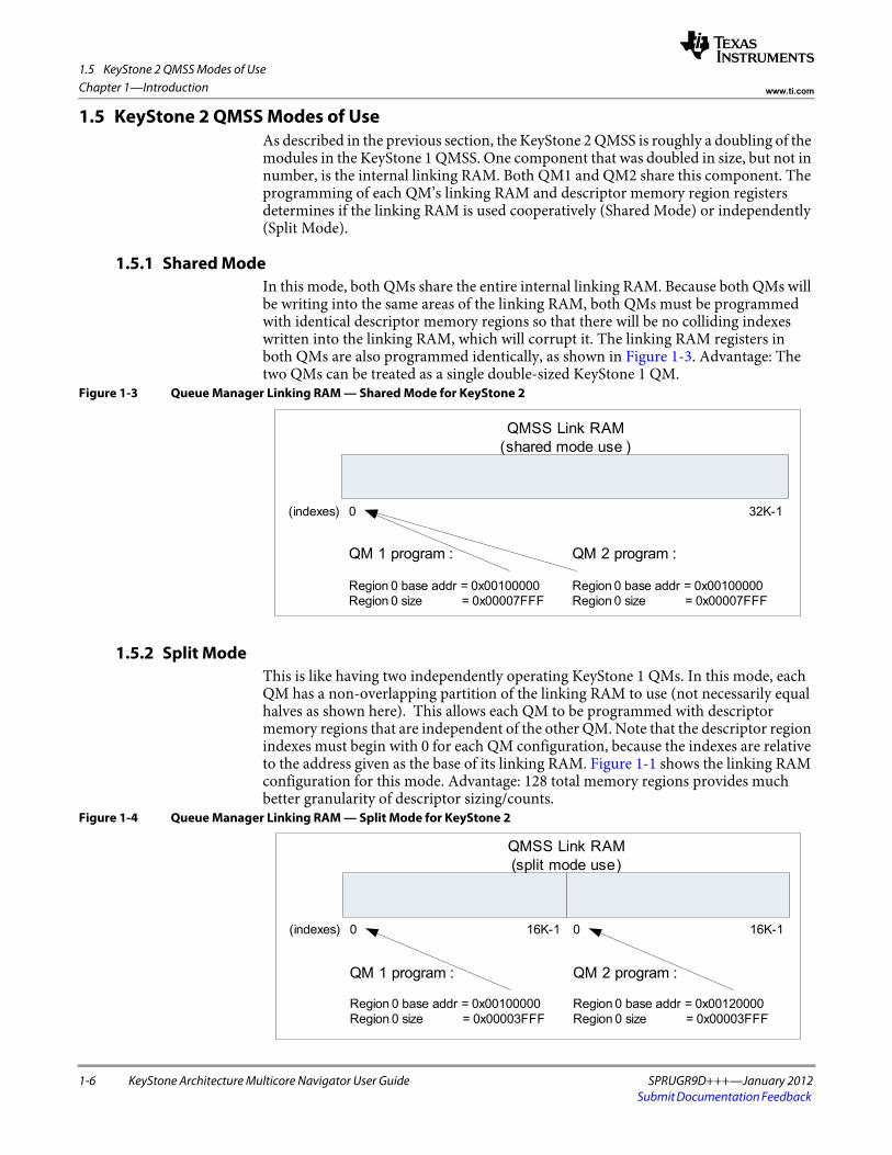
1.5 KeyStone 2 QMSS Modes of UseAs described in the previous section, the KeyStone 2 QMSS is roughly a doubling of the modules in the KeyStone 1 QMSS. One component that was doubled in size, but not in number, is the internal linking RAM. Both QM1 and QM2 share this component. The programming of each QM’s linking RAM and descriptor memory region registers determines if the linking RAM is used cooperatively (Shared Mode) or independently (Split Mode).
1.5.1 Shared ModeIn this mode, both QMs share the entire internal linking RAM. Because both QMs will be writing into the same areas of the linking RAM, both QMs must be programmed with identical descriptor memory regions so that there will be no colliding indexes written into the linking RAM, which will corrupt it. The linking RAM registers inboth QMs are also programmed identically, as shown in Figure 1-3. Advantage: The two QMs can be treated as a single double-sized KeyStone 1 QM.
Figure 1-3 Queue Manager Linking RAM — Shared Mode for KeyStone 2
1.5.2 Split ModeThis is like having two independently operating KeyStone 1 QMs. In this mode, each QM has a non-overlapping partition of the linking RAM to use (not necessarily equal halves as shown here). This allows each QM to be programmed with descriptor memory regions that are independent of the other QM. Note that the descriptor region indexes must begin with 0 for each QM configuration, because the indexes are relative to the address given as the base of its linking RAM. Figure 1-1 shows the linking RAM configuration for this mode. Advantage: 128 total memory regions provides much better granularity of descriptor sizing/counts.
Figure 1-4 Queue Manager Linking RAM — Split Mode for KeyStone 2
0
QMSS Link RAM (shared mode use )
32K-1(indexes)
QM 1 program :
Region 0 base addr = 0x00100000Region 0 size = 0x00007FFF
QM 2 program :
Region 0 base addr = 0x00100000Region 0 size = 0x00007FFF
0
QMSS Link RAM (split mode use)
16K-1(indexes) 016K-1
QM 1 program :
Region 0 base addr = 0x00100000Region 0 size = 0x00003FFF
QM 2 program :
Region 0 base addr = 0x00120000Region 0 size = 0x00003FFF

1.6 Overview
SPRUGR9D+++—January 2012 KeyStone Architecture Multicore Navigator User Guide 1-7Submit Documentation Feedback
Chapter 1—Introductionwww.ti.com
1.6 OverviewMulticore Navigator specifies the data structures used by Texas Instruments standard communications modules to facilitate direct memory access (DMA) and to provide a consistent application programming interface (API) to the host software in multi-core devices. The data structures and the API used to manipulate them will be jointly referred to as Multicore Navigator.
Frequent tasks are commonly offloaded from the host processor (DSP core) to peripheral hardware to increase system performance. Significant performance gains may result from careful design of the host software and communication module interface. In networking systems, packet transmission and reception are critical tasks. Texas Instruments has developed the Multicore Navigator standard, which is aimed at maximizing the efficiency of interaction between the host software and communications modules.
The design goals for Multicore Navigator are as follows:• Minimize host interaction • Maximize memory use efficiency• Maximize bus burst efficiency• Maximize symmetry between transmit/receive operations• Maximize scalability for number of connections / buffer sizes / queue sizes /
protocols supported• Minimize protocol specific features• Minimize complexity
1.7 Queue ManagerThe queue manager is a hardware module that is responsible for accelerating management of the packet queues. Packets are added to a packet queue by writing the 32-bit descriptor address to a particular memory mapped location in the queue manager module. Packets are de-queued by reading the same location for that particular queue. Multicore Navigator queue manager modules are capable of queuing only descriptors that have been allocated from the descriptor regions of the associated queue manager.
1.8 Packet DMA (PKTDMA)The Packet DMA is a DMA in which data destination is determined by a destination and free descriptor queue index, not an absolute memory address. In receive mode, the PKTDMA fetches a free descriptor, traverses the descriptor to find the buffer, PKTDMA transfers the payload into the buffer, and puts the descriptor into the destination queue. In transmit mode, the PKTDMA pops the descriptor from the Tx queue, traverses the descriptor, reads the payload from the buffer, and DMA transfers the payload to the transmit port.
1.9 Navigator CloudA Navigator Cloud is a set of PKTDMAs and descriptors. Neither PKTDMAs nor descriptors address the physical Queue Manager(s) directly, but instead use a “queue_manager:queue_number” (qmgr:qnum) notation and registers to create a logical mapping into the physical Queue Manager(s). All PKTDMAs with the same

1.10 PDSP Firmware
1-8 KeyStone Architecture Multicore Navigator User Guide SPRUGR9D+++—January 2012Submit Documentation Feedback
Chapter 1—Introduction www.ti.com
logical mapping are said to be part of the same Navigator Cloud. A descriptor can be sent to any PKTDMA in the same cloud, but may or may not transfer correctly through PKTDMAs in different clouds. A non-compatible logical qmgr:qnum mapping will cause descriptors to arrive in unexpected queues, potentially causing a memory leak.
1.10 PDSP FirmwareWithin the QMSS are two or eight PDSPs, each capable of running firmware that performs QMSS-related functions, such as accumulation, QoS, or event management (job load balancing). The accumulator firmware’s job is to poll a select number of queues looking for descriptors that have been pushed into them. Descriptors are popped from the queue and placed in a buffer provided by the host. When the list becomes full or a programmed time period expires, the accumulator triggers an interrupt to the host to read the buffer for descriptor information.
The accumulation firmware also provides a reclamation feature that automatically recycles descriptors to queues exactly as if the descriptor had been processed by the Tx PKTDMA.
The QoS firmware’s responsibility is to ensure that peripherals and the host CPU are not overwhelmed with packets. This is also known as traffic shaping, and is managed through the configuration of ingress and egress queues.
The timer periods for polling queues and for host interrupt triggering are programmable. Specific interrupt and queue assignments are listed later in this document.
Event management is handled by the Navigator Runtime software, which is a combination of PDSP firmware (scheduler) and CorePac software (dispatcher). Complete details are available in the Navigator Runtime user’s guide.

SPRUGR9D+++—January 2012 KeyStone Architecture Multicore Navigator User Guide 2-1Submit Documentation Feedback
Chapter 2
Operational Concepts
This chapter introduces the data movement concepts and data structures used by Multicore Navigator. Thorough understanding of these concepts is necessary for effective programming of the device. Low-level (bit field) descriptions are provided in later chapters.
2.1 "Packets" on page 2-2 2.2 "Queues" on page 2-2 2.3 "Queue Types" on page 2-3 2.4 "Descriptors" on page 2-4 2.5 "Packet DMA" on page 2-6 2.6 "Packet Transmission Overview" on page 2-7 2.7 "Packet Reception Overview" on page 2-9 2.8 "ARM Endianess" on page 2-11

2.1 Packets
2-2 KeyStone Architecture Multicore Navigator User Guide SPRUGR9D+++—January 2012Submit Documentation Feedback
Chapter 2—Operational Concepts www.ti.com
2.1 PacketsA packet is the logical grouping of a descriptor and the payload data attached to it. The payload data may be referred to as packet data or a data buffer, and depending on the descriptor type, may be contiguous with the descriptor fields, or may somewhere else in memory with a pointer stored in the descriptor.
2.2 QueuesQueues are used to hold pointers to packets while they are being passed between the host and / or any of the ports in the system. Queues are maintained within the queue manager module.
2.2.1 Packet QueuingQueuing of packets onto a packet queue is accomplished by writing a pointer to the descriptor (and in some cases the length of the packet) into a specific set of addresses within the queue manager module. Packets may be queued either onto the head or the tail of the queue and this is selected based on a bit in the Queue Register C for the queue. By default, packets will be added to the tail of a queue if the Queue Register C has not been written. The queue manager provides a unique set of addresses for adding packets for each queue that it manages. The host accesses the queue management registers via a queue proxy, which ensures that all pushes are atomic, eliminating the need for locking mechanisms in the device.
2.2.2 Packet De-queuingDe-queuing of packets from a packet queue is accomplished by reading the head packet pointer from the corresponding address in the queue manager. After the head pointer has been read, the queue manager will invalidate the head pointer and will replace it with the next packet pointer in the queue. This functionality, which is implemented in the queue manager, prevents the ports from needing to traverse linked lists and allows for certain optimizations to be performed within the queue manager.
2.2.3 Queue ProxyThe Queue Proxy is a module that provides atomic queue pushes across the cores in KeyStone architecture devices. The purpose of the proxy is to accept a Que N Reg C write followed by a Que N Reg D write without allowing another core to inject its own push. The method of pushing to the Queue Proxy is identical to writing to the Que N Reg C and D registers contained in the Queue Management Region, except at a different address (the same offset within the Queue Proxy Region). Each core is connected to the proxy and the proxy identifies it using its VBUS master ID. Simultaneous writes by two or more cores are arbitrated by round-robin. Queue pushes using only Reg D do not need to use the proxy and may write to the Queue Management Region. All registers in the Queue Proxy Region are write-only, and reads will return 0 (so there is no queue popping from this region). Because Que N Reg A and B are read only, they are not supported in the Queue Proxy.
Another important consideration is use of the Queue Proxy in a multitasking environment. The proxy cannot differentiate writes having different sources within the same core (such as multiple threads). If an application pushes to queues using Reg C and D, and multiple threads may push to the same queue, the application must protect these pushes using a resource management method such as critical sections, semaphore, etc.
2.3 Queue Types
SPRUGR9D+++—January 2012 KeyStone Architecture Multicore Navigator User Guide 2-3Submit Documentation Feedback
Chapter 2—Operational Conceptswww.ti.com
2.3 Queue TypesThis section describes the various types of queues that are used for transmitting and receiving packets through Multicore Navigator.
2.3.1 Transmit QueuesTx ports use packet queues referred to as transmit queues to store the packets that are waiting to be transmitted. Tx ports will require one or more packet queues dedicated to each transmit channel for this purpose. Typically, Tx queues are internally connected to a specific PKTDMA transmit channel.
2.3.2 Transmit Completion QueuesTx ports also use packet queues referred to as transmit completion queues to return packets to the host after they are transmitted. This can also be thought of as a Tx free descriptor queue. The number of queues required by the port or system for this purpose is driven by the requirements of the garbage collection software within the driver. Tx completion queues are used only when the packet descriptor indicates that the packet should be returned to a queue instead of directly recycling the descriptors to their queues of origin.
2.3.3 Receive QueuesRx ports use packet queues referred to as receive queues to forward completed received packets to the host or another peer port entity. Rx ports may be configured in various ways to forward the received packets onto any number of receive queues. Rx ports may choose to queue their receive packets based strictly on Rx channel, protocol type, priority, direct forwarding requirements (i.e. to another ports Tx queue), or any combination of these and this is application specific. In many cases, the receive queue is, in fact, also a transmit queue for another peer entity. It is just a matter of semantics with respect to which port is referenced in the system.
2.3.4 Free Descriptor Queues (FDQ)Rx ports use queues referred to as free descriptor queues that are initialized and ready for the Rx DMA to load them with incoming data. How they are initialized and handled by the PKTDMA differs by descriptor type:
2.3.4.1 Host Packet Free DescriptorsHost packets queued to a FDQ must have a buffer linked to them, and the buffer size set appropriately. The Rx DMA will pop the host packets as required, filling them up to their indicated buffer size, and, if needed, will pop additional host packet descriptors and link them as host buffers to the initial host packet. The Rx DMA will not look for host buffers pre-linked to host packets as is done by the Tx DMA.
2.3.4.2 Monolithic Free DescriptorsThe Rx DMA does not read any values from a monolithic FD. It is assumed by the PKTDMA that the size of the descriptor is large enough to hold all the packet data. Data exceeding the descriptor’s size will cause an overwrite of the next descriptor, which may cause undefined results. This calls for careful system initialization.

2.4 Descriptors
2-4 KeyStone Architecture Multicore Navigator User Guide SPRUGR9D+++—January 2012Submit Documentation Feedback
Chapter 2—Operational Concepts www.ti.com
2.4 DescriptorsDescriptors are small memory areas that describe the packet of data to be transferred through the system.
Descriptor types are discussed and shown in bit-level detail in the Descriptor Layouts chapter, but briefly, the descriptor types are:
2.4.1 Host PacketHost packet descriptors have a fixed size information (or description) area that contains a pointer to a data buffer, and optionally, a pointer to link one or more host buffer descriptors. Host packets are linked in Tx by the host application, and by the Rx DMA in Rx (host packets should not be prelinked when creating an Rx FDQ during initialization).
2.4.2 Host BufferHost buffer descriptors are interchangeable in descriptor size with host packets, but are never placed as the first link of a packet (this is referred to as start of packet). They can contain links to other host buffer descriptors.
2.4.3 Monolithic PacketMonolithic packet descriptors differ from host packet descriptors in that the descriptor area also contains the payload data, whereas the host packet contains a pointer to buffer located elsewhere. Monolithic packets are simpler to deal with, but are not as flexible as host packets.

2.4 Descriptors
SPRUGR9D+++—January 2012 KeyStone Architecture Multicore Navigator User Guide 2-5Submit Documentation Feedback
Chapter 2—Operational Conceptswww.ti.com
Figure 2-1 shows how the various types of descriptors are queued. For Host type descriptors, it illustrates how Host Buffers are linked to a Host Packet, while only the Host Packet is pushed and popped from a queue. Both Host and Monolithic descriptors may be pushed into the same queue, though in practice they are usually kept separate.
Figure 2-1 Packet Queuing Data Structure Diagram
Queue Manager(N = 0 to 8191)
Queue Packet
De-queue Packet
HostPacket
Descriptor(SOP)
Queue NHead
Pointer
Link
Link
Link
HostPacket
Descriptor(SOP)
NULL
Pointer
Queue
Link
NULL
Packet 1MOP Data
Buffer
Packet 1MOP Data
Buffer
Packet 2DataBuffer
Packet 1SOP Data
Buffer
Packet 3SOP Data
Buffer
Packet 1EOP Data
Buffer
NULL
HostBuffer
Descriptor(MOP)
HostBuffer
Descriptor(MOP)
HostBuffer
Descriptor(EOP)
MonolithicPacket
Descriptor

2.5 Packet DMA
2-6 KeyStone Architecture Multicore Navigator User Guide SPRUGR9D+++—January 2012Submit Documentation Feedback
Chapter 2—Operational Concepts www.ti.com
2.5 Packet DMAThe Packet DMA (or PKTDMA) used within Multicore Navigator is like most DMAs in that it is primarily concerned with moving data from point to point. It is unlike some DMAs in that it is unaware of the payload data’s structure. To the PKTDMA, all payloads are simple one-dimensional byte streams. Programming the PKTDMA is accomplished through correct initialization of descriptors, PKTDMA Rx/Tx channels, and Rx flows.
2.5.1 ChannelsEach PKTDMA in the system is configured with a number of receive (Rx) and transmit (Tx) channels (see section 5.4 ‘‘Packet DMA Channel Map’’ on page 5-11 for details). A channel may be thought of a pathway through the PKTDMA. Once the PKTDMA has started a packet on a channel, that channel cannot be used by any other packet until the current packet is completed. Because there are multiple channels for Rx and Tx, multiple packets may be in-flight simultaneously, and in both directions, because each PKTDMA contains separate DMA engines for Rx and Tx.
2.5.2 Rx FlowsFor transmit, the Tx DMA engine uses the information found in the descriptor fields to determine how to process the Tx packet. For receive, the Rx DMA uses a flow. A flow is a set of instructions that tells the Rx DMA how to process the Rx packet. It is important to note that there is not a correspondence between Rx channel and Rx flow, but rather between Rx packet and Rx flow. For example, one peripheral may create a single Rx flow for all packets across all channels, and another may create several flows for the packets on each channel.
For loopback PKTDMA modes (i.e. infrastructure cases), the Rx flow is specified in the Tx descriptor, in the SOURCE_TAG_LO field. The PKTDMA will pass this value to the streaming I/F as flow index. In non-loopback cases, the Rx flow is specified in the packet info structure of the Streaming I/F. In the event no Rx flow is specified, the Rx DMA will use Rx flow N for Rx channel N.

2.6 Packet Transmission Overview
SPRUGR9D+++—January 2012 KeyStone Architecture Multicore Navigator User Guide 2-7Submit Documentation Feedback
Chapter 2—Operational Conceptswww.ti.com
2.6 Packet Transmission OverviewAfter a Tx DMA channel has been initialized, it can begin to be used to transmit packets. Packet transmission involves the following steps:
1. The host is made aware of one or more chunks of data in memory that need to be transmitted as a packet. This may involve directly sourcing data from the host or it may involve data that has been forwarded from another data source in the system.
2. The host allocates a descriptor, usually from a Tx completion queue, and fills in the descriptor fields and payload data.
3. For host packet descriptors, the host allocates and populates host buffer descriptors as necessary to point to any remaining chunks of data that belong to this packet.
4. The host writes the pointer to the packet descriptor into a specific memory mapped location inside the queue manager that corresponds to one of the transmit queues for the desired DMA channel. Channels may provide more than one Tx queue and may provide a particular prioritization policy between the queues. This behavior is application-specific and is controlled by the DMA controller / scheduler implementation.
5. The queue manager provides a level sensitive status signal for the queue that indicates if any packets are currently pending. This level-sensitive status line is sent to the hardware block that is responsible for scheduling DMA operations.
6. The DMA controller is eventually brought into context for the corresponding channel and begins to process the packet.
7. The DMA controller reads the packet descriptor pointer and descriptor size hint information from the queue manager.
8. The DMA controller reads the packet descriptor from memory.9. The DMA controller empties the buffer (or for linked host packets, each buffer in
sequence specified by the next descriptor pointer) by transmitting the contents in one or more block data moves. The size of these blocks is application-specific.
10. When all data for the packet has been transmitted as specified in the packet size field, the DMA will write the pointer to the packet descriptor to the queue specified in the return queue manager / return queue number fields of the packet descriptor.
11. After the packet descriptor pointer has been written, the queue manager will indicate the status of the Tx completion queues to other ports / processors / prefetcher blocks using out-of-band level sensitive status lines. These status lines are set anytime a queue is non-empty.
12. While most types of peer entities and embedded processors are able to directly and efficiently use these level sensitive status lines, cached processors may require a hardware block to convert the level status into pulsed interrupts and to perform some level of aggregation of the descriptor pointers from the completion queues into lists.
13. Host responds to status change from queue manager and performs garbage collection as necessary for packet.

2.6 Packet Transmission Overview
2-8 KeyStone Architecture Multicore Navigator User Guide SPRUGR9D+++—January 2012Submit Documentation Feedback
Chapter 2—Operational Concepts www.ti.com
This complete process is shown in Figure 2-2.Figure 2-2 Packet Transmit Operation
Processor(may or may notbe running OS)
Queue Manager
TxQueue
TxCompletionQueue
Tx Port
1-4. ProcessorQueues TxPacket
5-9. Port TransmitsPacket
10. Port PostsPacket toCompletion Queue
13. Host PerformsGarbage Collection(may use list forperformance)
12. Tx PulsedInterruptto Host
Interrupt Generatorand (optional) List
Accumulator
11. Not EmptyLevel Status

2.7 Packet Reception Overview
SPRUGR9D+++—January 2012 KeyStone Architecture Multicore Navigator User Guide 2-9Submit Documentation Feedback
Chapter 2—Operational Conceptswww.ti.com
2.7 Packet Reception OverviewAfter an Rx DMA channel has been initialized, it can begin to be used to receive packets. Packet reception involves the following steps.
When packet reception begins on a given channel, the port will begin by fetching the first descriptor (or for host packets, descriptor + buffer) from the queue manager using a free descriptor queue that was programmed into the Rx flow being used by the packet. If the SOP buffer offset in the Rx flow is nonzero, then the port will begin writing data after the offset number of bytes in the SOP buffer. The port will then continue filling that buffer:
1. For host packets, the port will fetch additional descriptors + buffers as needed using the FDQ 1, 2, and 3 indexes for the 2nd, 3rd, and remaining buffers in the packet (as programmed in the Rx flow).
2. For monolithic packets, the port will continue writing after the SOP offset until EOP is reached (the host must insure that the packet length will fit into the descriptor or it will overwrite the next descriptor).
The PKTDMA performs the following operations when the entire packet has been received:
1. Writes the packet descriptor to memory. Most of the fields of the descriptor will be overwritten by the Rx DMA. See the Rx Overwrite column of the descriptor layouts in ‘‘Descriptor Layouts’’ on page 3-1 for field-specific detail. For monolithic packets, the DMA does not even read the descriptor until it is time to write to the descriptor fields at EOP.
2. Writes the packet descriptor pointer to the appropriate Rx queue. The absolute queue that each packet to be forwarded to on completion of reception will either be the queue that was specified in the RX_DEST_QMGR and RX_DEST_QNUM fields in the Rx flow. The port is explicitly allowed to override this destination queue using application specific methods.
The queue manager is responsible for indicating the status of the receive queues to other ports / embedded processors using out-of-band level sensitive status lines. These status lines are set anytime a queue is non-empty.
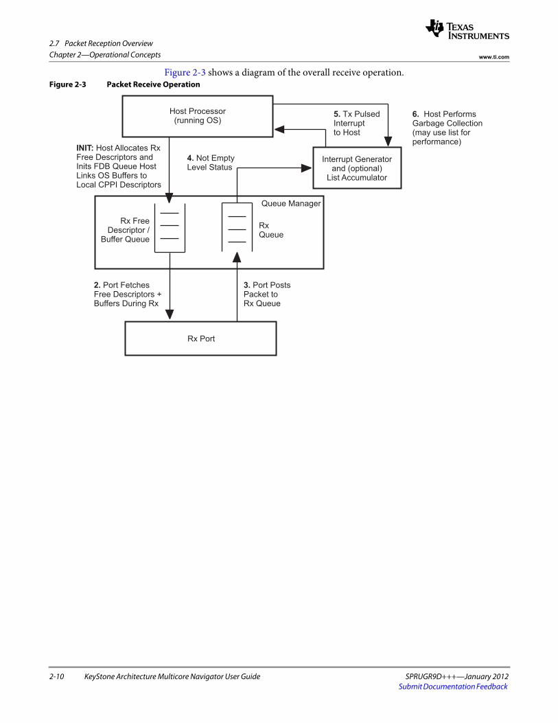
2.7 Packet Reception Overview
2-10 KeyStone Architecture Multicore Navigator User Guide SPRUGR9D+++—January 2012Submit Documentation Feedback
Chapter 2—Operational Concepts www.ti.com
Figure 2-3 shows a diagram of the overall receive operation. Figure 2-3 Packet Receive Operation
Host Processor(running OS)
Queue Manager
Rx FreeDescriptor /
Buffer Queue
RxQueue
Rx Port
2. Port FetchesFree Descriptors +Buffers During Rx
3. Port PostsPacket toRx Queue
6. Host PerformsGarbage Collection(may use list forperformance)
5. Tx PulsedInterruptto Host
Interrupt Generatorand (optional)
List Accumulator
4. Not EmptyLevel Status
INIT: Host Allocates RxFree Descriptors andInits FDB Queue HostLinks OS Buffers toLocal CPPI Descriptors

2.8 ARM Endianess
SPRUGR9D+++—January 2012 KeyStone Architecture Multicore Navigator User Guide 2-11Submit Documentation Feedback
Chapter 2—Operational Conceptswww.ti.com
2.8 ARM EndianessThis section pertains only to KeyStone devices containing an ARM processor.
Memory access between the ARM subsystem and the rest of the device is accomplished with the OCP2VBUSM bridge. This bridge performs endianess translations when the device is in big endian mode. The ARM always operates in little endian mode. For Navigator purposes, some data and data structures require manipulation when accessed by a program running on the ARM:
• Descriptors. The header portion needs to be byte swapped prior to pushing and following popping. Navigator uses a notion of descriptor ownership in that when the descriptor is pushed to a queue it is owned by the hardware, and owned by software when not pushed to a queue. Byte swapping follows this nicely in that when a descriptor is popped from a queue it should be byte swapped prior to reading header fields, then byte swapped again just before pushing it back to a queue. For linked Host descriptors, care must be taken to make sure that the next pointer has been byte swapped correctly for the ARM.
• Payload data for IP. For Tx data going into an IP (such as an FFTC), the data needs to be byte swapped prior to pushing the corresponding descriptors. Similarly, when consuming an Rx descriptor from an IP, the payload also needs to be swapped.
• Accumulator lists. The list of descriptor addresses provided by the Accumulator firmware needs to be byte swapped prior to consumption. Care must be taken due to the ping-pong nature of the lists; byte-swap only one side at a time - the side that is being consumed.

2.8 ARM Endianess
2-12 KeyStone Architecture Multicore Navigator User Guide SPRUGR9D+++—January 2012Submit Documentation Feedback
Chapter 2—Operational Concepts www.ti.com

SPRUGR9D+++—January 2012 KeyStone Architecture Multicore Navigator User Guide 3-1Submit Documentation Feedback
Chapter 3
Descriptor Layouts
Descriptors are memory areas that describe the contents of a packet. This memory may be co-located with the packet data, or may contain pointers to the data.
3.1 "Host Packet Descriptor" on page 3-2 3.2 "Host Buffer Descriptor" on page 3-7 3.3 "Monolithic Descriptor" on page 3-10

3.1 Host Packet Descriptor
3-2 KeyStone Architecture Multicore Navigator User Guide SPRUGR9D+++—January 2012Submit Documentation Feedback
Chapter 3—Descriptor Layouts www.ti.com
3.1 Host Packet DescriptorHost packet descriptors are designed to be used when the application requires support for true, unlimited fragment count scatter / gather-type operations. The host packet descriptor contains the following information:
• Indicator that identifies the descriptor as a host packet descriptor• Source and destination tags• Packet type• Packet length• Protocol-specific region size• Protocol-specific control / status bits• Pointer to the first valid byte in the SOP data buffer• Length of the SOP data buffer• Pointer to the next buffer descriptor in the packet• Software-specific information
Host packet descriptors always contain 32 bytes of required information and may also contain optional software-specific information and protocol-specific information. How much optional information (and therefore the allocated size of the descriptors) is required is application-dependent. The descriptor layout is shown in Figure 3-1.
Figure 3-1 Host Packet Descriptor Layout
Packet info (12 bytes)
Buffer info (8 bytes)
Linking info (4 bytes)
Original buffer info(8 bytes)
Extended packet info block (optional)Includes timestamp and software data
(16 bytes)
Protocol-specific data (optional)(0 to M bytes where M is a multiple of 4)
Other SW data (optional and user defined)
Packet info(12 bytes)
Buffer info (8 bytes)
Linking info(4 bytes)
Original buffer info(8 bytes)
Extended packet info block (optional)Includes timestamp and software data
(16 bytes)
Protocol-specific data (optional)(0 to M bytes where M is a multiple of 4)
Other SW data (optional and user defined)

3.1 Host Packet Descriptor
SPRUGR9D+++—January 2012 KeyStone Architecture Multicore Navigator User Guide 3-3Submit Documentation Feedback
Chapter 3—Descriptor Layoutswww.ti.com
Host packet descriptors may be linked with zero or more additional host buffer descriptors in a singly-linked-list fashion to form packets. Each host packet consists of a single host packet descriptor followed by a chain of zero or more host buffer descriptors linked together using the next descriptor pointer fields in the descriptors. The last descriptor in a host packet has a 0 next descriptor pointer.
The other SW data portion of the descriptor exists after all of the defined words and is reserved for use by the host software to store completely private data. This region is not used in any way by the DMA or queue manager modules in a Multicore Navigator system and these modules will not modify any bytes within this region.
The contents of the host packet descriptor words are detailed in the following tables:
Table 3-1 Host Packet Descriptor Packet Information Word 0 (PD Word 0)
Bits Name Description Rx Overwrite
31-30 Packet Id Host packet descriptor type identifier. Value is always 0 (0x0) for Host Packet descriptors. Yes
29-25 Packet Type This field indicates the type of this packet and is encoded as follows:
0-31 = To Be Assigned
Yes
24-23 Reserved Unused Yes
22 Protocol Specific Region Location
This field indicates the location of the protocol-specific words:0 = PS words are located in the descriptor1 = PS words are located in the SOP Buffer immediately prior to the data.
Yes
21-0 Packet Length The length of the packet data in bytes. If the packet length is less than the sum of the buffer lengths, then the packet data will be truncated. A packet length greater than the sum of the buffers is an error. The valid range for the packet length is 0 to 4M-1 bytes. If the packet length is set to 0, the port will not actually transmit any information. Instead, the port will perform buffer / descriptor reclamation as instructed in the return information in word 2.
Yes
End of Table 3-1
Table 3-2 Host Packet Descriptor Packet Information Word 1 (PD Word 1)
Bits Name Description Rx Overwrite
31-24 Source Tag - Hi This field is application-specific. During packet reception, the DMA controller in the port will overwrite this field as specified in the RX_SRC_TAG_HI_SEL field in the flow configuration table entry.
Configurable
23-16 Source Tag - Lo This field is application-specific. During packet reception, the DMA controller in the port will overwrite this field as specified in the RX_SRC_TAG_LO_SEL field in the flow configuration table entry. For Tx, this value supplies the Rx flow index to the Streaming I/F for infrastructure use.
Configurable
15-8 Dest Tag – Hi This field is application specific. During packet reception, the DMA controller in the port will overwrite this field as specified in the RX_DEST_TAG_HI_SEL field in the flow configuration table entry.
Configurable
7-0 Dest Tag - Lo This field is application specific. During packet reception, the DMA controller in the port will overwrite this field as specified in the RX_DEST_TAG_LO_SEL field in the flow configuration table entry.
Configurable
End of Table 3-2

3.1 Host Packet Descriptor
3-4 KeyStone Architecture Multicore Navigator User Guide SPRUGR9D+++—January 2012Submit Documentation Feedback
Chapter 3—Descriptor Layouts www.ti.com
Table 3-3 Host Packet Descriptor Packet Information Word 2 (PD Word 2)
Bits Name Description Rx Overwrite
31 Extended Packet Info Block Present
This field indicates the presence of the extended packet info block in the descriptor.0 = EPIB is not present1 = 16 byte EPIB is present
Yes
30 Reserved Unused Yes
29-24 Protocol Specific Valid Word Count
This field indicates the valid # of 32-bit words in the protocol-specific region. This is encoded in increments of 4 bytes as follows:
0 = 0 bytes1 = 4 bytes
…16 = 64 bytes
…
32 = 128 bytes
33-63 = Reserved
Yes
23-20 Error Flags This field contains error flags that can be assigned based on the packet type Yes
19-16 Protocol Specific Flags This field contains protocol-specific flags / information that can be assigned based on the packet type.
Yes
15 Return Policy This field indicates the return policy for this packet.0 = Entire packet (still linked together) should be returned to queue specified in bits 13-0 below.1 = Each buffer should be returned to queue specified in bits 13-0 of Word 2 in their respective
descriptors. The Tx DMA will return each buffer in sequence.
No
14 Return Push Policy This field indicates how a transmit DMA should return the descriptor pointers to the free queues. This field is encoded as follows:
0 = Descriptor must be returned to tail of queue1 = Descriptor must be returned to head of queue
This bit is used only when the Return Policy bit is set to 1.
No
13-12 Packet Return Queue Mgr #
This field indicates which of the four potential queue managers in the system the descriptor is to be returned to after transmission is complete. This field is not altered by the DMA during transmission or reception and should be initialized by the host.
No
11-0 Packet Return Queue # This field indicates the queue number within the selected queue manager that the descriptor is to be returned to after transmission is complete. The value 0xFFF is reserved.
No
End of Table 3-3
Table 3-4 Host Packet Descriptor Buffer 0 Info Word 0 (PD Word 3)
Bits Name Description Rx Overwrite
31-22 Reserved Unused Yes
21-0 Buffer 0 Length The buffer length field indicates how many valid data bytes are in the buffer. Unused or protocol-specific bytes at the beginning of the buffer are not counted in the buffer length field. This value will be overwritten during reception.
Yes
End of Table 3-4
Table 3-5 Host Packet Descriptor Buffer 0 Info Word 1 (PD Word 4)
Bits Name Description Rx Overwrite
31-0 Buffer 0 Pointer The buffer pointer is the byte-aligned memory address of the buffer associated with the buffer descriptor. This value will be written during reception. If the protocol-specific words are placed at the beginning of the SOP buffer, this pointer will point to the PS words. The offset to the data in that case must be calculated by the consumer using the protocol-specific valid word count from word 2. Usage note: For TX, it is a good practice to initialize this field and the Original Ptr field in word 7 with the actual buffer address, but this is the field that is used. For Rx, this field may be left uninitialized, or set to 0.
Yes
End of Table 3-5

3.1 Host Packet Descriptor
SPRUGR9D+++—January 2012 KeyStone Architecture Multicore Navigator User Guide 3-5Submit Documentation Feedback
Chapter 3—Descriptor Layoutswww.ti.com
Table 3-6 Host Packet Descriptor Linking Word (PD Word 5)
Bits Name Description Rx Overwrite
31-0 Next Descriptor Pointer The 32-bit word-aligned memory address of the next buffer descriptor in the packet. If the value of this pointer is 0, then the current buffer is the last buffer in the packet. The host sets the next descriptor pointer.
Yes
End of Table 3-6
Table 3-7 Host Packet Descriptor Original Buffer Info Word 0 (PD Word 6)
Bits Name Description Rx Overwrite
31-28 Original Buffer 0 Pool Index
This field is used to identify which pool the attached buffer was originally allocated from. This is distinct from the descriptor pool/queue index because a single buffer may be referenced by more that one descriptor. This is a software-only field that is not touched by the hardware.
No
27-22 Original Buffer 0 Reference Count
This field is used to indicate how many references have been made to the attached buffer by different descriptors. Multiple buffer references are commonly used to implement broadcast and multicast packet forwarding when zero packet data copies are desired. This is a software-only field that is not touched by the hardware.
No
21-0 Original Buffer 0 Length The buffer length field indicates the original size of the buffer in bytes. Data bytes are in the buffer. This value will not be overwritten during reception. This value is read by the Rx DMA to determine the actual buffer size as allocated by the host at initialization. Because the buffer length in Word 3 is overwritten by the Rx port during reception, this field is necessary to permanently store the buffer size information.
Usage Note: It is good practice to always set this field during initialization.
No
End of Table 3-7
Table 3-8 Host Packet Descriptor Original Buffer Info Word 1 (PD Word 7)
Bits Name Description Rx Overwrite
31-0 Original Buffer 0 Pointer The buffer pointer is the byte-aligned memory address of the buffer associated with the buffer descriptor. This value will not be overwritten during reception. This value is read by the RX DMA to determine the actual buffer location as allocated by the host at initialization. Because the buffer pointer in word 4 is overwritten by the Rx port during reception, this field is necessary to permanently store the buffer pointer information. Usage Note: It is good practice to always set this field during initialization, but is used only in Rx.
No
End of Table 3-8
Table 3-9 Host Packet Descriptor Extended Packet Info Block Word 0 (Optional) 1
Bits Name Description Rx Overwrite
31-0 Timestamp Info This field contains an application-specific timestamp that can be used for traffic shaping in a QoS enabled system.
Configurable
End of Table 3-9
1. This word is present only if the extended packet info block present bit is set in word 2.
Table 3-10 Host Packet Descriptor Extended Packet Info Block Word 1 (Optional) 1
Bits Name Description Rx Overwrite
31-0 Software Info 0 This field stores software-centric information that needs to travel with the packet through the stack. This information will be copied from the source descriptor to the destination descriptor whenever a prefetch operation is performed or when transferring through an infrastructure DMA node.
Configurable
End of Table 3-10
1. This word is present only if the Extended Packet Info Block present bit is set in Word 2.

3.1 Host Packet Descriptor
3-6 KeyStone Architecture Multicore Navigator User Guide SPRUGR9D+++—January 2012Submit Documentation Feedback
Chapter 3—Descriptor Layouts www.ti.com
Table 3-11 Host Packet Descriptor Extended Packet Info Block Word 2 (Optional) 1
Bits Name Description Rx Overwrite
31-0 Software Info 1 This field stores software centric information that needs to travel with the packet through the stack. This information will be copied from the source descriptor to the destination descriptor whenever a prefetch operation is performed or when transferring through an infrastructure DMA node.
Configurable
End of Table 3-11
1. This word is present only if the Extended Packet Info Block present bit is set in Word 2.
Table 3-12 Host Packet Descriptor Extended Packet Info Block Word 3 (Optional) 1
Bits Name Description Rx Overwrite
31-0 Software Info 2 This field stores software centric information that needs to travel with the packet through the stack. This information will be copied from the source descriptor to the destination descriptor whenever a prefetch operation is performed or when transferring through an infrastructure DMA node.
Configurable
End of Table 3-12
1. This word is present only if the Extended Packet Info Block present bit is set in Word 2.
Table 3-13 Host Packet Descriptor Protocol Specific Word N (Optional)
Bits Name Description Rx Overwrite
31-0 Protocol Specific Data N This field stores information that varies depending on the block and packet type. Configurable
End of Table 3-13

3.2 Host Buffer Descriptor
SPRUGR9D+++—January 2012 KeyStone Architecture Multicore Navigator User Guide 3-7Submit Documentation Feedback
Chapter 3—Descriptor Layoutswww.ti.com
3.2 Host Buffer DescriptorThe host buffer descriptor is identical in size and organization to a host packet descriptor but does not include valid information in the packet level fields and does not include a populated region for protocol-specific information. Host buffer descriptors are designed to be linked onto a host packet descriptor or another host buffer descriptor to provide support for unlimited scatter / gather type operations. Host buffer descriptors provide information about a single corresponding data buffer. Every host buffer descriptor stores the following information:
• Pointer to the first valid byte in the data buffer• Length of the data buffer• Pointer to the next buffer descriptor in the packet
Host buffer descriptors always contain 32 bytes of required information. Because it is a requirement that it is possible to convert a host descriptor between a buffer descriptor and a packet descriptor (by filling in the appropriate fields), in practice, host buffer descriptors will be allocated using the same sizes as host packet descriptors. The descriptor layout is shown in Figure 3-2.
A host packet descriptor and zero or more host buffer descriptors may be linked together using the next descriptor pointer fields to form packets. The last descriptor in a packet has a 0 next descriptor pointer. Each host buffer descriptor also points to a single data buffer.
Figure 3-2 Host Buffer Descriptor Layout
Reserved(10 bytes)
Buffer reclamation info(2 bytes)
Buffer info (8 bytes)
Linking info (4 bytes)
Original buffer info(8 bytes)
Reserved(10 bytes)
Buffer reclamation info(2 bytes)
Buffer info (8 bytes)
Linking info (4 bytes)
Original buffer info(8 bytes)

3.2 Host Buffer Descriptor
3-8 KeyStone Architecture Multicore Navigator User Guide SPRUGR9D+++—January 2012Submit Documentation Feedback
Chapter 3—Descriptor Layouts www.ti.com
The contents of the host buffer descriptor words are detailed in Table 3-14 through Table 3-21. The host buffer descriptor is designed to be interchangeable with host packet descriptors, with common fields residing in the same locations.
Table 3-14 Host Buffer Descriptor Reserved Word 0 (BD Word 0)
Bits Name Description Rx Overwrite
31-0 Reserved Reserved for host packet fields No
End of Table 3-14
Table 3-15 Host Buffer Descriptor Reserved Word 1 (BD Word 1)
Bits Name Description Rx Overwrite
31-0 Reserved Reserved for host packet fields No
End of Table 3-15
Table 3-16 Host Buffer Descriptor Buffer Reclamation Info (BD Word 2)
Bits Name Description Rx Overwrite
31-15 Reserved Reserved for host packet fields No
14 Return Push Policy This field indicates how a transmit DMA should return the descriptor pointers to the free queues. This field is encoded as follows:
0 = Descriptor must be returned to tail of queue1 = Descriptor must be returned to head of queue
This bit is used only when the Return Policy bit is set to 1.
No
13-12 Packet Return Queue Mgr # This field indicates which of the four potential queue managers in the system the descriptor is to be returned to after transmission is complete. This field is not altered by the DMA during transmission or reception and should be initialized by the host.
No
11-0 Packet Return Queue # This field indicates the queue number within the selected queue manager that the descriptor is to be returned to after transmission is complete.
No
End of Table 3-16
Table 3-17 Host Buffer Descriptor Buffer N Info Word 0 (BD Word 3)
Bits Name Description Rx Overwrite
31-22 Reserved Reserved for host packet fields Yes
21-0 Buffer N Length The buffer length field indicates how many valid data bytes are in the buffer. Unused or protocol-specific bytes at the beginning of the buffer are not counted in the buffer length field. This value will be overwritten during reception.
Yes
End of Table 3-17
Table 3-18 Host Buffer Descriptor Buffer N Info Word 1 (BD Word 4)
Bits Name Description Rx Overwrite
31-0 Buffer N Pointer The buffer pointer is the byte-aligned memory address of the buffer associated with the buffer descriptor. This value will not be overwritten during reception.
Yes
End of Table 3-18

3.2 Host Buffer Descriptor
SPRUGR9D+++—January 2012 KeyStone Architecture Multicore Navigator User Guide 3-9Submit Documentation Feedback
Chapter 3—Descriptor Layoutswww.ti.com
Table 3-19 Host Buffer Descriptor Linking Word (BD Word 5)
Bits Name Description Rx Overwrite
31-0 Next Descriptor Pointer The 32-bit word aligned memory address of the next buffer descriptor in the packet. This is the mechanism used to reference the next buffer descriptor from the current buffer descriptor. If the value of this pointer is 0, then the current buffer is the last buffer in the packet. This value will be overwritten during reception.
Yes
End of Table 3-19
Table 3-20 Host Buffer Descriptor Original Buffer Info Word 0 (BD Word 6)
Bits Name Description Rx Overwrite
31-28 Original Buffer 0 Pool Index
This field is used to identify which pool the attached buffer was originally allocated from. This is distinct from the descriptor pool/queue index because a single buffer may be referenced by more that one descriptor. This is a software-only field that is not touched by the hardware.
No
27-22 Original Buffer 0 Reference Count
This field is used to indicate how many references have been made to the attached buffer by different descriptors. Multiple buffer references are commonly used to implement broadcast and multicast packet forwarding when zero packet data copies are desired. This is a software-only field that is not touched by the hardware.
No
21-0 Original Buffer 0 Length The buffer length field indicates the original size of the buffer in bytes. Data bytes are in the buffer. This value will not be overwritten during reception. This value is read by the Rx DMA to determine the actual buffer size as allocated by the host at initialization. Because the buffer length in word 3 is overwritten by the Rx port during reception, this field is necessary to permanently store the buffer size information.
No
End of Table 3-20
Table 3-21 Host Buffer Descriptor Original Buffer Info Word 1 (BD Word 7)
Bits Name Description Rx Overwrite
31-0 Original Buffer 0 Pointer The buffer pointer is the byte-aligned memory address of the buffer associated with the buffer descriptor. This value will not be overwritten during reception. This value is read by the RX DMA to determine the actual buffer location as allocated by the host at initialization. Because the buffer pointer in word 4 is overwritten by the Rx port during reception, this field is necessary to permanently store the buffer pointer information.
No
End of Table 3-21
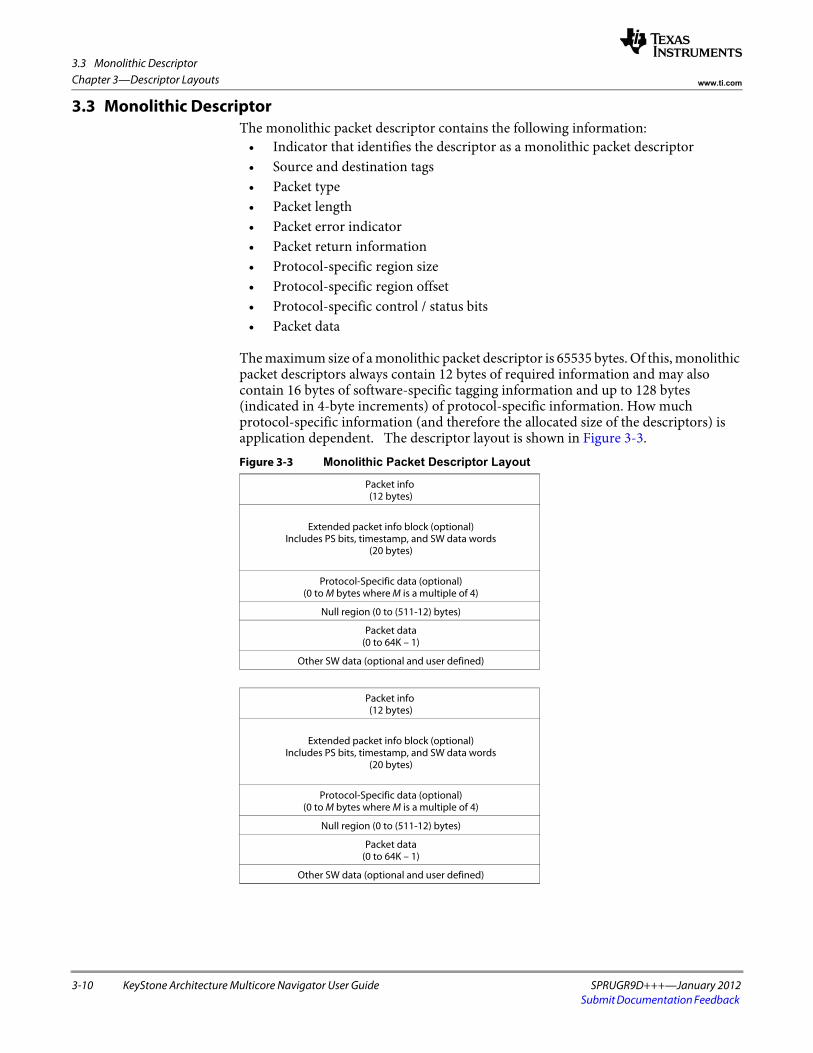
3.3 Monolithic Descriptor
3-10 KeyStone Architecture Multicore Navigator User Guide SPRUGR9D+++—January 2012Submit Documentation Feedback
Chapter 3—Descriptor Layouts www.ti.com
3.3 Monolithic DescriptorThe monolithic packet descriptor contains the following information:
• Indicator that identifies the descriptor as a monolithic packet descriptor • Source and destination tags• Packet type• Packet length• Packet error indicator• Packet return information• Protocol-specific region size• Protocol-specific region offset• Protocol-specific control / status bits• Packet data
The maximum size of a monolithic packet descriptor is 65535 bytes. Of this, monolithic packet descriptors always contain 12 bytes of required information and may also contain 16 bytes of software-specific tagging information and up to 128 bytes (indicated in 4-byte increments) of protocol-specific information. How much protocol-specific information (and therefore the allocated size of the descriptors) is application dependent. The descriptor layout is shown in Figure 3-3.
Figure 3-3 Monolithic Packet Descriptor Layout
Packet info (12 bytes)
Extended packet info block (optional)Includes PS bits, timestamp, and SW data words
(20 bytes)
Protocol-Specific data (optional)(0 to M bytes where M is a multiple of 4)
Null region (0 to (511-12) bytes)
Packet data(0 to 64K – 1)
Other SW data (optional and user defined)
Packet info (12 bytes)
Extended packet info block (optional)Includes PS bits, timestamp, and SW data words
(20 bytes)
Protocol-Specific data (optional)(0 to M bytes where M is a multiple of 4)
Null region (0 to (511-12) bytes)
Packet data(0 to 64K – 1)
Other SW data (optional and user defined)

3.3 Monolithic Descriptor
SPRUGR9D+++—January 2012 KeyStone Architecture Multicore Navigator User Guide 3-11Submit Documentation Feedback
Chapter 3—Descriptor Layoutswww.ti.com
The other SW data portion of the descriptor exists after all of the defined words and is reserved for use by the host software to store private data. This region is not used in any way by the DMA or queue manager modules in a Multicore Navigator system and these modules will not modify any bytes within this region.
A note on the placement of data with respect to the optional EPIB block: If EPIB is present, the 16 bytes of EPIB data begins at byte offset 16, and PS or packet data may begin at byte offset 32 (from the descriptor address). If EPIB is not present, PS or packet data may begin at byte offset 12 (from the descriptor address).
The contents of the monolithic packet descriptor words are detailed in the following tables:
Table 3-22 Monolithic Packet Descriptor Word 0
Bits Name Description Rx Overwrite
31-30 Packet Id Monolithic packet descriptor type. Value is always 2 (0x02) for monolithic descriptors. Yes
29-25 Packet Type This field indicates the type of this packet and is encoded as follows: 0-31 = To Be Assigned
Yes
24-16 Data Offset This field indicates the byte offset from byte 0 of this descriptor to the location where the valid data begins.
On Rx, this value is set equal to the value for the SOP offset given in the Rx DMA channel’s monolithic control register.
When a monolithic packet is processed, this value may be modified in order to add or remove bytes to or from the beginning of the packet.
The value for this field can range from 0-511 bytes, which means that the maximum NULL region can be 511-12 bytes, because byte 0 is the start of the 12 byte packet info area.
Note that the value of this field must always be greater than or equal to 4 times the value given in the Protocol Specific Valid Word Count field.
Yes
15-0 Packet Length The length of the packet data in bytes. The valid range is from 0 to 65535 bytes. NOTE: The sum of the data offset field and the packet length must not exceed 64KB or the defined size of the descriptor. To do so is an error, and may cause transmission problems through the Streaming Interface.
Yes
End of Table 3-22
Table 3-23 Monolithic Packet Descriptor Word 1
Bits Name Description Rx Overwrite
31-24 Source Tag - Hi This field is application-specific. During packet reception, the DMA controller in the port will overwrite this field as specified in the RX_SRC_TAG_HI_SEL field in the flow configuration table entry.
Configurable
23-16 Source Tag - Lo This field is application-specific. During packet reception, the DMA controller in the port will overwrite this field as specified in the RX_SRC_TAG_LO_SEL field in the flow configuration table entry. For Tx, this value supplies the Rx flow index to the streaming I/F for infrastructure use.
Configurable
15-8 Dest Tag – Hi This field is application-specific. During packet reception, the DMA controller in the port will overwrite this field as specified in the RX_DEST_TAG_HI_SEL field in the flow configuration table entry.
Configurable
7-0 Dest Tag - Lo This field is application-specific. During packet reception, the DMA controller in the port will overwrite this field as specified in the RX_DEST_TAG_LO_SEL field in the flow configuration table entry.
Configurable
End of Table 3-23

3.3 Monolithic Descriptor
3-12 KeyStone Architecture Multicore Navigator User Guide SPRUGR9D+++—January 2012Submit Documentation Feedback
Chapter 3—Descriptor Layouts www.ti.com
Table 3-24 Monolithic Packet Descriptor Word 2
Bits Name Description Rx Overwrite
31 Extended Packet Info Block Present
This field indicates the presence of the extended packet info block in the descriptor.
0 = EPIB is not present
1 = 16 byte EPIB is present
Yes
30 Reserved Unused Yes
29-24 Protocol Specific Valid Word Count
This field indicates the valid number of 32-bit words in the protocol-specific region. This is encoded in increments of 4 bytes as follows:
0 = 0 bytes1 = 4 bytes…16 = 64 bytes…32 = 128 bytes 33-63 = Reserved
Yes
23-20 Error Flags This field contains error flags that can be assigned based on the packet type. Yes
19-16 Protocol Specific Flags
This field contains protocol-specific flags / information that can be assigned based on the packet type. Yes
15 Reserved Unused No
14 Return Push Policy This field indicates how a transmit DMA should return the descriptor pointers to the free queues. This field is encoded as follows:
0 = Descriptor must be returned to tail of queue1 = Descriptor must be returned to head of queue
No
13-12 Packet Return Queue Mgr #
This field indicates which of the four potential queue managers in the system the descriptor is to be returned to after transmission is complete. This field is not altered by the DMA during transmission or reception and should be initialized by the host.
No
11-0 Packet Return Queue #
This field indicates the queue number within the selected queue manager that the descriptor is to be returned to after transmission is complete.
No
End of Table 3-24
Table 3-25 Monolithic Extended Packet NULL Word (Optional) 1
Bits Name Description Rx Overwrite
31-0 Reserved This field is present only to align the extended packet words to a 128-bit boundary in memory. This word can be used for host SW scratchpad because it will not be copied or overwritten by the DMA components.
No
End of Table 3-25
1. This word is present only if the Extended Packet Info Block present bit is set in word 2.
Table 3-26 Monolithic Extended Packet Info Word 0 (Optional) 1
Bits Name Description Rx Overwrite
31-0 Timestamp Info This field contains an application-specific timestamp that can be used for traffic shaping in a QoS-enabled system.
Configurable
End of Table 3-26
1. This word is present only if the Extended Packet Info Block present bit is set in word 2.

3.3 Monolithic Descriptor
SPRUGR9D+++—January 2012 KeyStone Architecture Multicore Navigator User Guide 3-13Submit Documentation Feedback
Chapter 3—Descriptor Layoutswww.ti.com
Table 3-27 Monolithic Extended Packet Info Word 1 (Optional) 1
Bits Name Description Rx Overwrite
31-0 Software Info 0 This field stores software-centric information that needs to travel with the packet through the stack. This information will be copied from the source descriptor to the destination descriptor whenever a prefetch operation is performed or when transferring through an infrastructure DMA node.
Configurable
End of Table 3-27
1. This word is present only if the Extended Packet Info Block present bit is set in word 2.
Table 3-28 Monolithic Extended Packet Info Word 2 (Optional) 1
Bits Name Description Rx Overwrite
31-0 Software Info 1 This field stores software-centric information that needs to travel with the packet through the stack. This information will be copied from the source descriptor to the destination descriptor whenever a prefetch operation is performed or when transferring through an infrastructure DMA node.
Configurable
End of Table 3-28
1. This word is present only if the Extended Packet Info Block present bit is set in word 2.
Table 3-29 Monolithic Extended Packet Info Word 3 (Optional) 1
Bits Name Description Rx Overwrite
31-0 Software Info 2 This field stores software-centric information that needs to travel with the packet through the stack. This information will be copied from the source descriptor to the destination descriptor whenever a prefetch operation is performed or when transferring through an infrastructure DMA node.
Configurable
End of Table 3-29
1. This word is present only if the Extended Packet Info Block present bit is set in word 2.
Table 3-30 Monolithic Packet Descriptor Protocol Specific Word M (Optional) 1
Bits Name Description Rx Overwrite
31-0 Protocol Specific Data N This field stores information that varies depending on the packet type. Configurable
End of Table 3-30
1. These words, if present, immediately follow the software data block information.
Table 3-31 Monolithic Packet Descriptor Payload Data Words 0-N 1 2
Bits Name Description Rx Overwrite
31-0 Packet Data N These words store the packet payload data. Yes
End of Table 3-31
1. The payload data follows the protocol-specific words at an offset specified in the data offset field of word 0.
2. This field is endian-specific. In other words, this is the only field in the descriptor that changes based on the endianess of the system.

3.3 Monolithic Descriptor
3-14 KeyStone Architecture Multicore Navigator User Guide SPRUGR9D+++—January 2012Submit Documentation Feedback
Chapter 3—Descriptor Layouts www.ti.com

SPRUGR9D+++—January 2012 KeyStone Architecture Multicore Navigator User Guide 4-1Submit Documentation Feedback
Chapter 4
Registers
The following sections describe the memory mapped registers within each region of the Queue Manager Sub-system and PKTDMA. All Multicore Navigator registers support 32-bit accesses only.
4.1 "Queue Manager" on page 4-2 4.2 "Packet DMA" on page 4-16 4.3 "QMSS PDSPs" on page 4-34 4.4 "QMSS Interrupt Distributor" on page 4-53

4.1 Queue Manager
4-2 KeyStone Architecture Multicore Navigator User Guide SPRUGR9D+++—January 2012Submit Documentation Feedback
Chapter 4—Registers www.ti.com
4.1 Queue ManagerThe following sections describe the registers in each of the queue manager register regions, for each queue manager. The register descriptions provide each register’s offset from the region’ base address.
4.1.1 Queue Configuration RegionTable 4-1 shows registers within each queue manager config region.
Table 4-1 Queue Configuration Region Registers
Offset Name Description
0x00000000 Revision Register The Revision Register contains the major and minor revisions for the module.
0x00000008 Queue Diversion Register The Queue Diversion Register is used to transfer the contents of one queue onto another queue.
0x0000000C Linking RAM Region 0 Base Address Register
The Linking RAM Region 0 Base Address Register is used to set the base address for the first portion of the linking RAM. This address must be 32-bit-aligned. It is used by the queue manager to calculate the 32-bit linking address for a given descriptor index.
0x00000010 Linking RAM Region 0 Size Register
The linking RAM Region 0 Size Register is used to set the size of the array of linking pointers that are located in region 0 of Linking RAM. The size specified the number of descriptors for which linking information is stored in this region.
0x00000014 Linking RAM Region 1 Base Address Register
The linking RAM Region 1 Base Address Register is used to set the base address for the second portion of the linking RAM. This base address is used by the queue manager to calculate the 32-bit linking address from the descriptor index. All descriptors with index higher than that given in linking RAM 0 Size register have linking information stored in linking RAM region 1.
0x00000020 - 0x0000005C
Free Descriptor/Buffer Starvation Count Registers N (0 – 15)
The Free Descriptor/Buffer Queue Starvation Count Registers provide statistics about how many starvation events are occurring on the Rx free descriptor/buffer queues.
End of Table 4-1
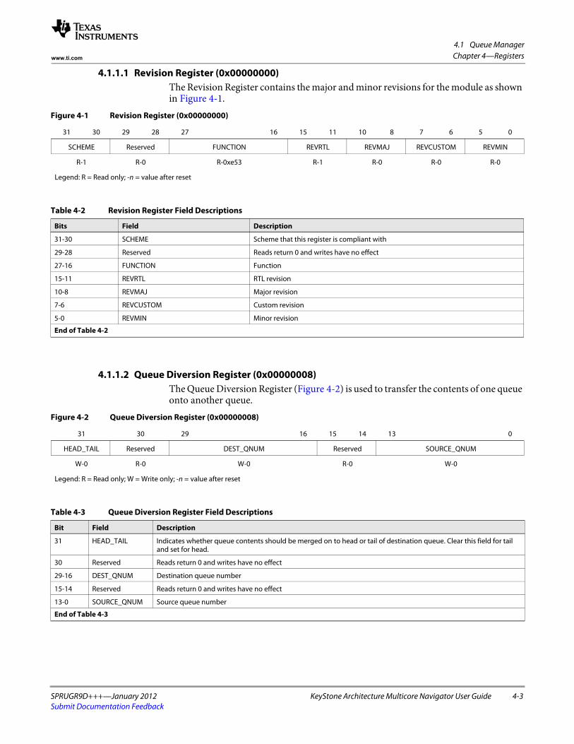
4.1 Queue Manager
SPRUGR9D+++—January 2012 KeyStone Architecture Multicore Navigator User Guide 4-3Submit Documentation Feedback
Chapter 4—Registerswww.ti.com
4.1.1.1 Revision Register (0x00000000)The Revision Register contains the major and minor revisions for the module as shown in Figure 4-1.
4.1.1.2 Queue Diversion Register (0x00000008)The Queue Diversion Register (Figure 4-2) is used to transfer the contents of one queue onto another queue.
Figure 4-1 Revision Register (0x00000000)
31 30 29 28 27 16 15 11 10 8 7 6 5 0
SCHEME Reserved FUNCTION REVRTL REVMAJ REVCUSTOM REVMIN
R-1 R-0 R-0xe53 R-1 R-0 R-0 R-0
Legend: R = Read only; -n = value after reset
Table 4-2 Revision Register Field Descriptions
Bits Field Description
31-30 SCHEME Scheme that this register is compliant with
29-28 Reserved Reads return 0 and writes have no effect
27-16 FUNCTION Function
15-11 REVRTL RTL revision
10-8 REVMAJ Major revision
7-6 REVCUSTOM Custom revision
5-0 REVMIN Minor revision
End of Table 4-2
Figure 4-2 Queue Diversion Register (0x00000008)
31 30 29 16 15 14 13 0
HEAD_TAIL Reserved DEST_QNUM Reserved SOURCE_QNUM
W-0 R-0 W-0 R-0 W-0
Legend: R = Read only; W = Write only; -n = value after reset
Table 4-3 Queue Diversion Register Field Descriptions
Bit Field Description
31 HEAD_TAIL Indicates whether queue contents should be merged on to head or tail of destination queue. Clear this field for tail and set for head.
30 Reserved Reads return 0 and writes have no effect
29-16 DEST_QNUM Destination queue number
15-14 Reserved Reads return 0 and writes have no effect
13-0 SOURCE_QNUM Source queue number
End of Table 4-3

4.1 Queue Manager
4-4 KeyStone Architecture Multicore Navigator User Guide SPRUGR9D+++—January 2012Submit Documentation Feedback
Chapter 4—Registers www.ti.com
4.1.1.3 Linking RAM Region 0 Base Address Register (0x0000000C)The linking RAM Region 0 Base Address Register (Figure 4-3) is used to set the base address for the first portion of the linking RAM. This address must be 32-bit aligned. It is used by the queue manager to calculate the 32-bit linking address for a given descriptor index.
4.1.1.4 Linking RAM Region 0 Size Register (0x00000010)The Linking RAM Region 0 Size Register (Figure 4-4) is used to set the size of the array of linking pointers that are located in region 0 of linking RAM. The value specified in this register defines the range of descriptor indexes in Linking RAM 0. Any descriptor index less than or equal to this value will be considered in Linking RAM 0. A descriptor index greater than this value will be in Linking RAM 1.
Figure 4-3 Linking RAM Region 0 Base Address Register (0x0000000C)
31 0
REGION0_BASE
R/W-0
Legend: R/W = Read/Write; -n = value after reset
Table 4-4 Linking RAM Region 0 Base Address Register Field Descriptions
Bit Field Description
31-0 REGION0_BASE This field stores the base address for the first region of the linking RAM. This may be anywhere in 32-bit address space but would be typically located in on-chip memory. To use the QMSS’ internal Linking RAM, specify a value of 0x00080000 for Keystone1, 0x00100000 for Keystone2’s QM1. Depending on the Shared/Split mode configuration, the value for QM2 will be 0x00100000 (Shared mode) or 0x00100000 +(8 * number_of_descriptors_in_QM1_split).
End of Table 4-4
Figure 4-4 Linking RAM Region 0 Size Register (0x00000010)
31 19 18 0
Reserved REGION0_SIZE
R-0 R/W-0
Legend: R = Read only; R/W = Read/Write; -n = value after reset
Table 4-5 Linking RAM Region 0 Size Register Field Descriptions
Bit Field Description
31-19 Reserved Reads return 0 and writes have no effect
18-0 REGION0_SIZE This field indicates the number of entries that are contained in the linking RAM region 0. A descriptor with index less than or equal to region0_size value has its linking location in region 0.
Keystone1: To specify the entire QMSS internal Linking RAM to be used for Linking RAM 0, use the value 0x3FFF. If no Linking RAM 1 is used, or if the total descriptors used is less than 16K, it is still safe to use 0x3FFF, because every descriptor index must be less than 16K (0x4000).
Keystone2: To specify the entire QMSS internal Linking RAM to be used for Linking RAM 0, use the value 0x7FFF. This creates a Shared mode configuration. For a Split mode configuration, first decide how many descriptors of the 32K will be used by each QM, then program those values minus one.
End of Table 4-5

4.1 Queue Manager
SPRUGR9D+++—January 2012 KeyStone Architecture Multicore Navigator User Guide 4-5Submit Documentation Feedback
Chapter 4—Registerswww.ti.com
4.1.1.5 Linking RAM Region 1 Base Address Register (0x00000014)The Linking RAM Region 1 Base Address Register (Figure 4-5) is used to set the base address for the second portion of the linking RAM. This base address is used by the queue manager to calculate the 32-bit linking address from the descriptor index. All descriptors with index higher than that given in Linking RAM 0 Size register have linking information stored in linking RAM region 1.
4.1.1.6 Free Descriptor/Buffer Starvation Count Register N (0x00000020 + N×4)The Free Descriptor/Buffer Queue Starvation Count Registers (Figure 4-6)provide statistics about how many starvation events are occurring on the Rx free descriptor/buffer queues. It does not support byte accesses. Register 0 reads the first four queues with starvation counters; register 1 reads the next four queues, etc.
Figure 4-5 Linking RAM Region 1 Base Address Register (0x00000014)
31 0
REGION1_BASE
R/W-0
Legend: R/W = Read/Write; -n = value after reset
Table 4-6 Linking RAM Region 1 Base Address Register Field Descriptions
Bit Field Description
31-0 REGION1_BASE This field stores the base address for the second region of the linking RAM. This may be anywhere in 32-bit address space but would be typically located in off-chip memory. For Keystone2, each QM may specify it’s own secondary external linking RAM.
End of Table 4-6
Figure 4-6 Free Descriptor/Buffer Starvation Count Register N (0x00000020 + N×4)
31 24 23 16 15 8 7 0
FDBQ3_STARVE_CNT FDBQ2_STARVE_CNT FDBQ1_STARVE_CNT FDBQ0_STARVE_CNT
COR-0 COR-0 COR-0 COR-0
Legend: COR = Clear On Read; -n = value after reset
Table 4-7 Free Descriptor/Buffer Starvation Count Register N Field Descriptions
Bit Field Description
31-24 FDBQ3_STARVE_CNT This field increments each time the Free Descriptor/Buffer Queue N+3 is read while it is empty. This field is cleared when read.
23-16 FDBQ2_STARVE_CNT This field increments each time the Free Descriptor/Buffer Queue N+2 is read while it is empty. This field is cleared when read.
15-8 FDBQ1_STARVE_CNT This field increments each time the Free Descriptor/Buffer Queue N+1 is read while it is empty. This field is cleared when read.
7-0 FDBQ0_STARVE_CNT This field increments each time the Free Descriptor/Buffer Queue N is read while it is empty. This field is cleared when read.
End of Table 4-7

4.1 Queue Manager
4-6 KeyStone Architecture Multicore Navigator User Guide SPRUGR9D+++—January 2012Submit Documentation Feedback
Chapter 4—Registers www.ti.com
4.1.2 Queue Status RAMThis is a special read-only memory on a separate slave port where the queue manager maintains status bits for each queue. This RAM may be read by host software, and is also read by the accumulation firmware.
Each word of this memory is organized as shown in Figure 4-7 and represents the threshold status for queues 32N+31 down to 32N. A bit is set (1) if the threshold (as programmed by the Queue N Status and Configuration Register D register) is met or exceeded.
Figure 4-7 Queue Threshold Status Word N (0x00000000 - 0x000003FC)
31 0
QTHRESHOLDN
R-0
Legend: R = Read only; -n = value after reset
Table 4-8 Queue Threshold Status Word N Field Descriptions
Bit Field Description
31-0 QTHRESHOLDN This field indicates the queue threshold status for queues[32N+1:32N]. Each bit represents one queue.
End of Table 4-8

4.1 Queue Manager
SPRUGR9D+++—January 2012 KeyStone Architecture Multicore Navigator User Guide 4-7Submit Documentation Feedback
Chapter 4—Registerswww.ti.com
4.1.3 Descriptor Memory Setup RegionThe registers in this region program one of the queue manager’s descriptor memory regions.
Note—Memory regions and packet descriptors must be aligned to 16 byte boundaries. For performance reasons, it is preferable to align descriptors and data buffers to 64 byte boundaries if they are larger than 32 bytes. This allows data to flow through the chip with the fewest bus transactions.
4.1.3.1 Memory Region R Base Address Register (0x00000000 + 16×R)The Memory Region R Base Address Register (Figure 4-8) is written by the host to set the base address of memory region R. This memory region will store a number of descriptors of a particular size as determined by the Memory Region R Control Register. Note: In Keystone1, memory region base addresses must be set in ascending order, i.e. region 0 must be at a lower address than region 1, region 1 must be at a lower address than region 2, etc. In Keystone2, this restriction is removed, and memory regions need not be programmed in order (i.e. you can program regions 1,2,3,5 and not 4).
Table 4-9 Descriptor Memory Setup Region Registers
Offset Name Description
0x00000000 +
16 × R
Memory Region R Base Address Register (0...19, or 0...63 for KeyStone 2)
The Memory Region R Base Address Register is written by the host to set the base address of memory region R. This memory region will store a number of descriptors of a particular size as determined by the Memory Region R Control Register.
0x00000004 +
16 × R
Memory Region R Start Index Register (0...19, or 0...63 for KeyStone 2)
The Memory Region R Start Index Register is written by the host to configure index of the first descriptor in this memory region.
0x00000008 +
16 × R
Memory Region R Descriptor Setup Register (0...19, or 0...63 for KeyStone 2)
The Memory Region R Descriptor Setup Register is written by the host to configure various descriptor related parameters of this memory region.
End of Table 4-9
Figure 4-8 Memory Region R Base Address Register (0x00000000 + 16×R)
31 0
REGR_BAS
R/W-0
Legend: R/W = Read/Write; -n = value after reset
Table 4-10 Memory Region R Base Address Register Field Descriptions
Bit Field Description
31-0 REGR_BASE This field contains the base address of the memory region R.
End of Table 4-10

4.1 Queue Manager
4-8 KeyStone Architecture Multicore Navigator User Guide SPRUGR9D+++—January 2012Submit Documentation Feedback
Chapter 4—Registers www.ti.com
4.1.3.2 Memory Region R Start Index Register (0x00000004 + 16×R)The Memory Region R Start Index Register (Figure 4-9) is written by the host to configure index of the first descriptor in this memory region.
4.1.3.3 Memory Region R Descriptor Setup Register (0x00000008 + 16×R)The Memory Region R Descriptor Setup Register (Figure 4-10) is written by the host to configure various descriptor-related parameters of this memory region.
Figure 4-9 Memory Region R Start Index Register (0x00000004 + 16×R)
31 19 18 0
Reserved START_INDEX
R-0 R/W-0
Legend: R = Read only; R/W = Read/Write; -n = value after reset
Table 4-11 Memory Region R Start Index Register Field Descriptions
Bit Field Description
31-19 Reserved Reads return 0 and writes have no effect
18-0 START_INDEX This field indicates where in linking RAM does the descriptor linking information corresponding to memory region R starts.
End of Table 4-11
Figure 4-10 Memory Region R Descriptor Setup Register (0x00000008 + 16×R)
31 29 28 16 15 4 3 0
Reserved DESC_SIZE Reserved REG_SIZE
R-0 R/W-0 R-0 R/W-0
Legend: R = Read only; R/W = Read/Write; -n = value after reset
Table 4-12 Memory Region R Descriptor Setup Register Field Descriptions
Bit Field Description
31-29 Reserved Reads return 0 and writes have no effect.
28-16 DESC_SIZE This field indicates the size of each descriptor in this memory region. The value programmed is the multiplier minus 1 that needs to be applied to 16 to get the actual descriptor size. So, for 16-byte and 64-byte descriptors, the value programmed will be 0 and 3 respectively.
15-4 Reserved Reads return 0 and writes have no effect.
3-0 REG_SIZE This field indicates the size of the memory region (in terms of number of descriptors). It is an encoded value that specifies region size as 2(5+reg_size) number of descriptors.
End of Table 4-12
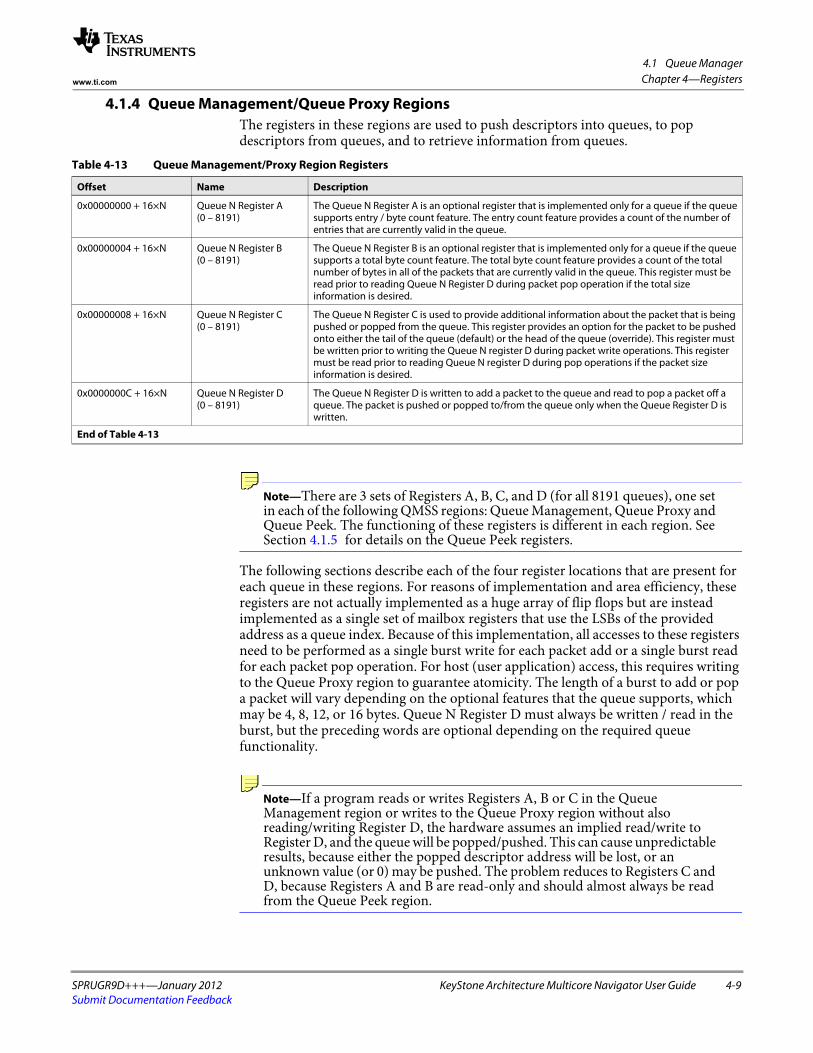
4.1 Queue Manager
SPRUGR9D+++—January 2012 KeyStone Architecture Multicore Navigator User Guide 4-9Submit Documentation Feedback
Chapter 4—Registerswww.ti.com
4.1.4 Queue Management/Queue Proxy RegionsThe registers in these regions are used to push descriptors into queues, to pop descriptors from queues, and to retrieve information from queues.
Note—There are 3 sets of Registers A, B, C, and D (for all 8191 queues), one set in each of the following QMSS regions: Queue Management, Queue Proxy and Queue Peek. The functioning of these registers is different in each region. See Section 4.1.5 for details on the Queue Peek registers.
The following sections describe each of the four register locations that are present for each queue in these regions. For reasons of implementation and area efficiency, these registers are not actually implemented as a huge array of flip flops but are instead implemented as a single set of mailbox registers that use the LSBs of the provided address as a queue index. Because of this implementation, all accesses to these registers need to be performed as a single burst write for each packet add or a single burst read for each packet pop operation. For host (user application) access, this requires writing to the Queue Proxy region to guarantee atomicity. The length of a burst to add or pop a packet will vary depending on the optional features that the queue supports, which may be 4, 8, 12, or 16 bytes. Queue N Register D must always be written / read in the burst, but the preceding words are optional depending on the required queue functionality.
Note—If a program reads or writes Registers A, B or C in the Queue Management region or writes to the Queue Proxy region without also reading/writing Register D, the hardware assumes an implied read/write to Register D, and the queue will be popped/pushed. This can cause unpredictable results, because either the popped descriptor address will be lost, or an unknown value (or 0) may be pushed. The problem reduces to Registers C and D, because Registers A and B are read-only and should almost always be read from the Queue Peek region.
Table 4-13 Queue Management/Proxy Region Registers
Offset Name Description
0x00000000 + 16×N Queue N Register A(0 – 8191)
The Queue N Register A is an optional register that is implemented only for a queue if the queue supports entry / byte count feature. The entry count feature provides a count of the number of entries that are currently valid in the queue.
0x00000004 + 16×N Queue N Register B(0 – 8191)
The Queue N Register B is an optional register that is implemented only for a queue if the queue supports a total byte count feature. The total byte count feature provides a count of the total number of bytes in all of the packets that are currently valid in the queue. This register must be read prior to reading Queue N Register D during packet pop operation if the total size information is desired.
0x00000008 + 16×N Queue N Register C(0 – 8191)
The Queue N Register C is used to provide additional information about the packet that is being pushed or popped from the queue. This register provides an option for the packet to be pushed onto either the tail of the queue (default) or the head of the queue (override). This register must be written prior to writing the Queue N register D during packet write operations. This register must be read prior to reading Queue N register D during pop operations if the packet size information is desired.
0x0000000C + 16×N Queue N Register D(0 – 8191)
The Queue N Register D is written to add a packet to the queue and read to pop a packet off a queue. The packet is pushed or popped to/from the queue only when the Queue Register D is written.
End of Table 4-13

4.1 Queue Manager
4-10 KeyStone Architecture Multicore Navigator User Guide SPRUGR9D+++—January 2012Submit Documentation Feedback
Chapter 4—Registers www.ti.com
4.1.4.1 Queue N Register A (0x00000000 + 16×N)The Queue N Register A (Figure 4-11) is an optional register that is implemented only for a queue if the queue supports entry/byte count feature. The entry count feature provides a count of the number of entries that are currently valid in the queue.
4.1.4.2 Queue N Register B (0x00000004 + 16×N)The Queue N Register B (Figure 4-12) is an optional register that is implemented only for a queue if the queue supports a total byte count feature. The total byte count feature provides a count of the total number of bytes in all of the packets that are currently valid in the queue, as has been written to the Queue N Register C in descriptor pushes (note that the QM never reads descriptors). This register must be read prior to reading Queue N Register D during packet pop operation if the total size information is desired. Also, this is a saturating 32-bit counter.
Figure 4-11 Queue N Register A (0x00000000 + 16×N)
31 19 18 0
Reserved QUEUE_ENTRY_COUNT
R-0 R-0
Legend: R = Read only; -n = value after reset
Table 4-14 Queue N Register A Field Descriptions
Bit Field Description
31-19 Reserved Reads return 0 and writes have no effect.
18-0 QUEUE_ENTRY_COUNT This field indicates how many packets are currently queued on the queue. This count is incremented by 1 whenever a packet is added to the queue. This count is decremented by 1 whenever a packet is popped from the queue. Do not read this register unless you also intend on popping the queue with Reg D. To obtain the descriptor count without also popping the queue, use Queue N Status and Configuration Reg A in the Queue Peek region.
End of Table 4-14
Figure 4-12 Queue N Register B (0x00000004 + 16×N)
31 0
QUEUE_BYTE_COUNT
R-0
Legend: R = Read only; -n = value after reset
Table 4-15 Queue N Register B Field Descriptions
Bit Field Description
31-0 QUEUE_BYTE_COUNT This field indicates how many bytes total are contained in all of the packets that are currently queued on this queue. Do not read this register unless you also intend on popping the queue with Reg D. To obtain the byte count without also popping the queue, use Queue N Status and Configuration Reg B in the Queue Peek region.
End of Table 4-15
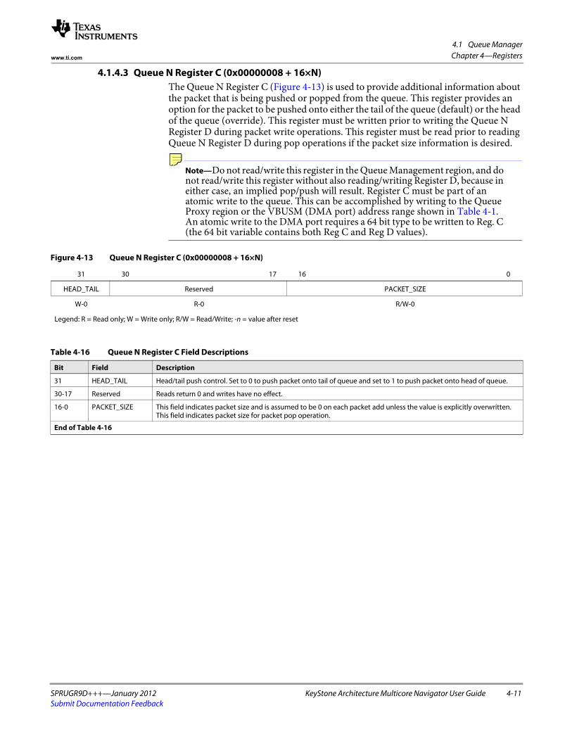
4.1 Queue Manager
SPRUGR9D+++—January 2012 KeyStone Architecture Multicore Navigator User Guide 4-11Submit Documentation Feedback
Chapter 4—Registerswww.ti.com
4.1.4.3 Queue N Register C (0x00000008 + 16×N)The Queue N Register C (Figure 4-13) is used to provide additional information about the packet that is being pushed or popped from the queue. This register provides an option for the packet to be pushed onto either the tail of the queue (default) or the head of the queue (override). This register must be written prior to writing the Queue N Register D during packet write operations. This register must be read prior to reading Queue N Register D during pop operations if the packet size information is desired.
Note—Do not read/write this register in the Queue Management region, and do not read/write this register without also reading/writing Register D, because in either case, an implied pop/push will result. Register C must be part of an atomic write to the queue. This can be accomplished by writing to the Queue Proxy region or the VBUSM (DMA port) address range shown in Table 4-1. An atomic write to the DMA port requires a 64 bit type to be written to Reg. C (the 64 bit variable contains both Reg C and Reg D values).
Figure 4-13 Queue N Register C (0x00000008 + 16×N)
31 30 17 16 0
HEAD_TAIL Reserved PACKET_SIZE
W-0 R-0 R/W-0
Legend: R = Read only; W = Write only; R/W = Read/Write; -n = value after reset
Table 4-16 Queue N Register C Field Descriptions
Bit Field Description
31 HEAD_TAIL Head/tail push control. Set to 0 to push packet onto tail of queue and set to 1 to push packet onto head of queue.
30-17 Reserved Reads return 0 and writes have no effect.
16-0 PACKET_SIZE This field indicates packet size and is assumed to be 0 on each packet add unless the value is explicitly overwritten. This field indicates packet size for packet pop operation.
End of Table 4-16

4.1 Queue Manager
4-12 KeyStone Architecture Multicore Navigator User Guide SPRUGR9D+++—January 2012Submit Documentation Feedback
Chapter 4—Registers www.ti.com
4.1.4.4 Queue N Register D (0x0000000C + 16×N)The Queue N Register D (Figure 4-14) is written to add a packet to the queue and read to pop a packet off a queue. The packet is pushed to or popped from the queue only when the Queue Register D is written.
Note—Remember that all accesses to Registers A, B, C and D are considered by the hardware an atomic access. If reading/writing Register C with this register, please read the atomicity note in the section for Register C. Reading Registers A and B are best done using the Queue Peek region. Please refer to the above register descriptions for more information. Pushing to the VBUSM address is faster than the VBUSP address due to the deeper write buffer (and no stalls), but popping is faster via the VBUSP address to due the higher VBUSM SCR latency for pop operations.
CAUTION—A potential for a race condition exists when descriptors or data from one core’s L2 is transferred to another core’s L2: If the descriptor or data is modified immediately before the push, and the push address uses VBUSP, it is possible that the PKTDMA may not see the updated memory. To avoid this condition, do one of the following: 1) push using the VBUSM address, or 2) add an MFENCE instruction prior to the push.
Figure 4-14 Queue N Register D (0x0000000C + 16×N)
31 4 3 0
DESC_PTR DESC_SIZE
R/W-0 R/W-0
Legend: R/W = Read/Write; -n = value after reset
Table 4-17 Queue N Register D Field Descriptions
Bit Field Description
31-4 DESC_PTR Descriptor pointer. It will be read as 0 if the queue is empty. It will indicate a 16-byte-aligned address that points to a descriptor when the queue is not empty. Writing a zero will force queue empty, possibly losing queued descriptors.
3-0 DESC_SIZE Initial descriptor fetch size (encoded in 16-byte increments as follows):• 0 = 16 bytes• 1 = 32 bytes• 2 = 48 bytes• ...• 15 = 256 bytes.
This field should be set to the smallest value that is greater than or equal to the size of the entire control portion of the descriptor. This includes all descriptor information (including the protocol specific bytes) with the exception of the data portion of the monolithic descriptor. If this value is smaller than the control portion size of the descriptor, the PKTDMA will not fetch the remainder and will hang. For AIF Monolithic Mode, this value should always be set to 3. If the queue is empty, this field will return a 0x0 when read.
When the Packet DMA pushes descriptors to Tx Return queues, this field will be zero. When it pushes to Rx Destination queues, it will be set based on the constructed descriptor.
End of Table 4-17

4.1 Queue Manager
SPRUGR9D+++—January 2012 KeyStone Architecture Multicore Navigator User Guide 4-13Submit Documentation Feedback
Chapter 4—Registerswww.ti.com
4.1.5 Queue Peek RegionThe registers in this region are used get the descriptor and byte counts of queues, and to set the queue thresholds for Tx queues that drive select Tx DMA channels in Multicore Navigator peripherals.
Note—This region may be write protected by MPU2 (a Memory Protection Unit) depending on the version of boot used. Please refer to the MPU Users Guide for details on how to grant write access.
4.1.5.1 Queue N Status and Configuration Register A (0x00000000 + 16×N)The Queue N Status and Configuration Register A (Figure 4-15) is an optional register that is implemented only for a queue if the queue supports entry/byte count feature. The entry count feature provides a count of the number of entries that are currently valid in the queue.
Table 4-18 Queue Peek Region Registers
Offset Name Description
0x00000000 + 16×N Queue N Status and Configuration Register A(0 – 8191)
This is an optional register that is implemented only for a queue if the queue supports entry/byte count feature. The entry count feature provides a count of the number of entries that are currently valid in the queue.
0x00000004 + 16×N Queue N Status and Configuration Register B(0 – 8191)
This is an optional register that is implemented only for a queue if the queue supports a total byte count feature. The total byte count feature provides a count of the total number of bytes in all of the packets that are currently valid in the queue.
0x00000008 + 16×N Queue N Status and Configuration Register C(0 – 8191)
This register specifies the packet size for the head element of a queue.
0x0000000C + 16×N Queue N Status and Configuration Register D(0 – 8191)
This register is used to configure the queue threshold feature. When enabled, the queue threshold pin (for select Tx queues) gets asserted when the number of items in a queue is above or below a threshold value. This register is available for each queue.
End of Table 4-18
Figure 4-15 Queue N Status and Configuration Register A (0x00000000 + 16×N)
31 19 18 0
Reserved QUEUE_ENTRY_COUNT
R-0 R-0
Legend: R = Read only; -n = value after reset
Table 4-19 Queue N Status and Configuration Register A Field Descriptions
Bit Field Description
31-19 Reserved Reads return 0 and writes have no effect.
18-0 QUEUE_ENTRY_COUNT This field indicates how many packets are currently queued on the queue.
End of Table 4-19

4.1 Queue Manager
4-14 KeyStone Architecture Multicore Navigator User Guide SPRUGR9D+++—January 2012Submit Documentation Feedback
Chapter 4—Registers www.ti.com
4.1.5.2 Queue N Status and Configuration Register B (0x00000004 + 16×N)The Queue N Status and Configuration Register B (Figure 4-16) is an optional register that is implemented only for a queue if the queue supports a total byte count feature. The total byte count feature provides a count of the total number of bytes in all of the packets that are currently valid in the queue.
4.1.5.3 Queue N Status and Configuration Register C (0x00000008 + 16×N)The Queue N Status and Configuration Register C (Figure 4-17) specifies the packet size for the head element of a queue, if a value was written (via Queue N Register C) when the element was pushed. It is 0 otherwise.
Figure 4-16 Queue N Status and Configuration Register B (0x00000004 + 16×N)
31 0
QUEUE_BYTE_COUNT
R-0
Legend: R = Read only; -n = value after reset
Table 4-20 Queue N Status and Configuration Register B Field Descriptions
Bit Field Description
31-0 QUEUE_BYTE_COUNT This field indicates how many bytes total are contained in all of the packets that are currently queued on this queue.
End of Table 4-20
Figure 4-17 Queue N Status and Configuration Register C (0x00000008 + 16×N)
31 17 16 0
Reserved PACKET_SIZE
R-0 R-0
Legend: R = Read only; -n = value after reset
Table 4-21 Queue N Status and Configuration Register C Field Descriptions
Bit Field Description
31-17 Reserved Reads return 0 and writes have no effect.
16-0 PACKET_SIZE This field indicates packet size of the head element of a queue.
End of Table 4-21

4.1 Queue Manager
SPRUGR9D+++—January 2012 KeyStone Architecture Multicore Navigator User Guide 4-15Submit Documentation Feedback
Chapter 4—Registerswww.ti.com
4.1.5.4 Queue N Status and Configuration Register D (0x0000000C + 16×N)The Queue N Status and Configuration Register D (Figure 4-18) is used to configure the queue threshold feature. When enabled, the Queue Status RAM is updated with each push and pop. This register is available for all queues. Also, because the accumulation firmware reads the Queue Status RAM, these registers must be programmed for all queues used by the accumulator, with the value 0x81, which will cause the status bit to set on non-zero count, and clear on zero.
Note—This register is write protected by MPU2 (Memory Protection Unit). Please refer to the MPU Users Guide for details on how to grant write access.
Figure 4-18 Queue N Status and Configuration Register D (0x0000000C + 16×N)
31 8 7 6 4 3 0
Reserved THRESHOLD_HILO Reserved THRESHOLD
R-0 R/W-1 R-0 R/W-1
Legend: R = Read only; R/W = Read/Write; -n = value after reset
Table 4-22 Queue N Status and Configuration Register D Field Descriptions
Bit Field Description
31-8 Reserved Reads return 0 and writes have no effect.
7 THRESHOLD_HILO This field indicates whether the number of items in a queue should be greater than, equal to, or less than the threshold before the QUEUE_ECNT_STATUS[queue] bit is asserted. If this field is set, then the status bit is set (1) when the size of the queue is at least as big as the set threshold value. If this bit is cleared, then the status bit is set (1) when the size of the queue is less than the set threshold value.
6-4 Reserved Reads return 0 and writes have no effect.
3-0 THRESHOLD This field indicates the threshold at which the queue threshold bit is set. This field is internally represented as a ten bit number. The threshold is 0 when this field is 0. The threshold is 0x3FF when it is 10 or higher. It is (2threshold - 1) in the internal representation for other values.
End of Table 4-22

4.2 Packet DMA
4-16 KeyStone Architecture Multicore Navigator User Guide SPRUGR9D+++—January 2012Submit Documentation Feedback
Chapter 4—Registers www.ti.com
4.2 Packet DMAThe following sections describe the registers in each of the Packet DMA’s register regions.
Each PKTDMA supports a unique number of channels and flow configurations appropriate for its use (see Table 4-23). The counts of channels and flows determine the addressable size of the register region.
4.2.1 Global Control Registers RegionThe PKTDMA Global Control Registers region, which configure items not related to channels or flows. The address map for this region is shown in Table 4-24:
Table 4-23 PKTDMA Channel and Flow Counts
QMSS SRIO PA AIF2 BCP FFTC (any)
Tx Channels 32 16 9 129 8 4
Rx Channels 32 16 24 129 8 4
Rx Flow Configs 64 32 32 129 64 8
End of Table 4-23
Table 4-24 PKTDMA Global Control Region Registers
Byte Address Name
0x00 Revision Register
0x04 Performance Control Register
0x08 Emulation Control Register
0x0C Priority Control Register
0x10 QM0 Base Address Register
0x14 QM1 Base Address Register
0x18 QM2 Base Address Register
0x1C QM3 Base Address Register
End of Table 4-24

4.2 Packet DMA
SPRUGR9D+++—January 2012 KeyStone Architecture Multicore Navigator User Guide 4-17Submit Documentation Feedback
Chapter 4—Registerswww.ti.com
4.2.1.1 Revision Register (0x00)The Revision Register (Figure 4-19) contains the major and minor revisions for the module.
4.2.1.2 Performance Control Register (0x04)The Performance Control Register (Figure 4-20) is used to adjust the performance of the PKTDMA in the system.
Figure 4-19 Revision Register (0x00)
31 30 29 16 15 11 10 8 7 0
Reserved MODID REVRTL REVMAJ REVMIN
R-0 R-0x4E5A R-1 R-0x1 R-0
Legend: R = Read only; -n = value after reset;
Table 4-25 Revision Register Field Descriptions
Bit Field Description
31-30 Reserved Reads return 0 and writes have no effect.
29-16 MODID Module ID field
15-11 REVRTL RTL revision. Will vary depending on release.
10-8 REVMAJ Major revision.
7-0 REVMIN Minor revision.
End of Table 4-25
Figure 4-20 Performance Control Register (0x04)
31 22 21 16 15 0
Reserved WARB_FIFO_DEPTH TIMEOUT
R-0 R/W-0x20 R/W-0
Legend: R = Read only; R/W = Read/Write; -n = value after reset
Table 4-26 Performance Control Register Field Descriptions
Bit Field Description
31-22 Reserved Reads return 0 and writes have no effect.
21-16 WARB_FIFO_DEPTH This field sets the depth of the write arbitration FIFO, which stores write transaction information between the command arbiter and write data arbiters in the Bus Interface Unit. This value can be set to a range of 1 to 32. Setting this field to smaller values will prevent the PKTDMA from having an excess of write transactions outstanding whose data is still waiting to be transferred. System performance can suffer if write commands are allowed to be issued long before the corresponding write data will be transferred. This field allows the command count to be optimized based on system dynamics.
15-0 TIMEOUT This field sets a timeout duration in clock cycles. It controls the minimum amount of time that an Rx channel will be required to wait when it encounters a buffer starvation condition and the Rx error handling bit is set to 1 (packet is to be preserved - no discard). If the Rx error handling bit in the flow table is cleared, this field will have no effect on the Rx operation. When this field is set to 0, the Rx engine will not force an Rx channel to wait after encountering a starvation event (the feature is disabled). When this field is set to a value other than 0, the Rx engine will force any channel whose associated flow had the Rx error handling bit asserted and which encounters starvation to wait for at least the specified # of clock cycles before coming into context again to retry the access to the QM. This is intended to control potentially debilitating effects on the QM performance that can be caused by the PKTDMA modules continually polling the QM. The exact number of clock cycles between QM access attempts is not important and will not be exact. The only guarantee is that the number of cycles waited will be at least as large as TIMEOUT.
End of Table 4-26

4.2 Packet DMA
4-18 KeyStone Architecture Multicore Navigator User Guide SPRUGR9D+++—January 2012Submit Documentation Feedback
Chapter 4—Registers www.ti.com
4.2.1.3 Emulation Control Register (0x08)The Emulation Control Register (Figure 4-21) is used to control the behavior of the DMA when the emususp input is asserted.
4.2.1.4 Priority Control Register (0x0C)
The Priority Control Register (Figure 4-22) is used to control the priority of the transactions that the DMA generates on its master (VBUSM) interface. They set sideband signals on the bus; they do not affect anything within the DMA.
Figure 4-21 Emulation Control Register (0x08)
31 30 2 1 0
LOOPBACK Reserved SOFT FREE
R/W-1 R-0 R/W-0 R/W-0
Legend: R = Read only; R/W = Read/Write; -n = value after reset
Table 4-27 Emulation Control Register Field Descriptions
Bit Field Description
31 LOOPBACK Loopback enable. When set (1), causes the Tx Streaming I/F to loopback to the Rx Streaming I/F. For normal operation, this bit must be set for the QMSS PKTDMA, and cleared (0) for all others. This field has a reset value of 1.
30-2 Reserved Reads return 0 and writes have no effect.
1 SOFT TBD
0 FREE TBD
End of Table 4-27
Figure 4-22 Priority Control Register (0x0C)
31 19 18 16 15 3 2 0
Reserved RX_PRIORITY Reserved TX_PRIORITY
R-0 R/W-0 R-0 R/W-0
Legend: R = Read only; R/W = Read/Write; -n = value after reset
Table 4-28 Priority Control Register Field Descriptions
Bit Field Description
31-19 Reserved Reads return 0 and writes have no effect.
18-16 RX_PRIORITY This field contains the 3-bit value that will be output on the mem_cpriority and mem_cepriority outputs during all Rx transactions.
31-19 Reserved Reads return 0 and writes have no effect.
2-0 TX_PRIORITY This field contains the 3-bit value that will be output on the mem_cpriority and mem_cepriority outputs during all Tx transactions.
End of Table 4-28

4.2 Packet DMA
SPRUGR9D+++—January 2012 KeyStone Architecture Multicore Navigator User Guide 4-19Submit Documentation Feedback
Chapter 4—Registerswww.ti.com
4.2.1.5 QMn Base Address Register (0x10, 0x14, 0x18, 0x1c)The QMn Base Address Registers (Figure 4-23) are used to create four logical queue managers that map into a physical queue manager.
Figure 4-23 QMn Base Address Register (0x04)
31 0
QM_BASE_ADDR
R/W-0
Legend: R/W = Read/Write; -n = value after reset
Table 4-29 Qmn Base Address Register Field Descriptions
Bit Field Description
31-0 QM_BASE_ADDR This field programs the base address for the nth logical queue manager for the PKTDMA. Typically, these registers point into the Queue Management region of a physical queue manager on the same device, or a remote queue manager on another device. They must be programmed using the VBUSM address, which is 0x34020000 for physical queue 0 (Keystone1). The reset value for QM0 Base Address Register defaults to this address, but QM1, QM2, and QM3 reset to 0. The most common programming of these registers is the following:• QM0: 0x34020000 (point to queue 0 - this is also the reset value)• QM1: 0x34030000 (point to queue 4096)• QM2: na• QM3: na
The PKTDMA will obtain the VBUSM address for Tx queues via one of these registers. For all Keystone1 devices, QM0 is used. For Keystone2, QM0 is used for all PKTDMAs that get their queue pend signals from physical Queue Manager 1. QM2 is used for PKTDMAs get get their queue pend signals from physical Queue Manager 2.
These registers define a “Navigator Cloud” (see Section 1.9). All PKTDMAs in a given cloud must have these registers set to the same values. The other components of a Navigator Cloud are: 1) Descriptors, and 2) Rx Flows. Their qmgr:qnum fields must be compatible with the base addresses defined here or descriptors may be erroneously routed.
• Keystone2 notes:• These registers have Keystone1 reset values and must be programmed with appropriate Keystone 2 VBUSM
addresses.• The simplest configuration is to set the first two registers to address physical Queue Manager 1 (0x23a80000,
0x23a90000) and the last two registers to physical Queue Manager 2 (0x23aa0000, 0x23ab0000), then make sure descriptors and Rx Flows are likewise configured.
End of Table 4-29

4.2 Packet DMA
4-20 KeyStone Architecture Multicore Navigator User Guide SPRUGR9D+++—January 2012Submit Documentation Feedback
Chapter 4—Registers www.ti.com
4.2.2 Tx DMA Channel Configuration RegionThis region is used to configure the Tx DMA channels. The memory map for the Tx DMA Channel Configuration Region is shown in Table 4-30:
4.2.2.1 Tx Channel N Global Configuration Register A (0x000 + 32×N)The Tx Channel Configuration Register A (Figure 4-24) contains real-time control and status information for the Tx DMA channel. The fields in this register can safely be changed while the channel is in operation.
Table 4-30 Tx DMA Channel Config Region Registers
Address Register
0x000 Tx Channel 0 Global Configuration Register A
0x004 Tx Channel 0 Global Configuration Register B
0x008 – 0x01F Reserved
0x020 Tx Channel 1 Global Configuration Register A
0x024 Tx Channel 1 Global Configuration Register B
0x028 – 0x03F Reserved
0x000 + N × 32 Tx Channel N Global Configuration Register A
0x004 + N × 32 Tx Channel N Global Configuration Register B
0x008 + N × 32 Reserved
End of Table 4-30
Figure 4-24 Tx Channel N Global Configuration Register A (0x000 + 32×N)
31 30 29 28 0
TX_ENABLE TX_TEARDOWN TX_PAUSE Reserved
R/W-0 R/W R/W R-0
Legend: R = Read only; R/W = Read/Write; -n = value after reset
Table 4-31 Tx Channel N Global Configuration Register A Field Descriptions
Bit Field Description
31 TX_ENABLE This field enables or disables the channel. Disabling a channel halts operation on the channel after the current block transfer is completed. Disabling a channel in the middle of a packet transfer may result in underflow conditions in the attached application block and data loss. This field is encoded as follows:
0 = channel is disabled1 = channel is enabled
This field will be cleared after a channel teardown is complete.
30 TX_TEARDOWN Setting this bit will request the channel to be torn down. This field will remain set after a channel teardown is complete.
29 TX_PAUSE Setting this bit will cause the channel to pause processing at the next packet boundary. This is a more graceful method of halting processing than disabling the channel as it will not allow any current packets to underflow.
28-0 Reserved Reads return 0 and writes have no effect.
End of Table 4-31

4.2 Packet DMA
SPRUGR9D+++—January 2012 KeyStone Architecture Multicore Navigator User Guide 4-21Submit Documentation Feedback
Chapter 4—Registerswww.ti.com
4.2.2.2 Tx Channel N Global Configuration Register B (0x004 + 32×N)The Tx Channel Configuration Register B (Figure 4-25) is used to initialize special handling modes for the Tx DMA channel. This register should be written only when the channel is disabled (tx_enable is 0).
Figure 4-25 Tx Channel N Global Configuration Register B (0x004 + 32×N)
31 30 29 28 25 24 23 0
Reserved TX_FILT_EINFO TX_FILT_PSWORDS Reserved TX_AIF_MONO_MODE Reserved
R-0 W W R-0 W R-0
Legend: R = Read only; W = Write only; -n = value after reset
Table 4-32 Tx Channel N Global Configuration Register B Field Descriptions
Bit Field Description
31 Reserved Reads return 0 and writes have no effect.
30 TX_FILT_EINFO Tx Filter Software Info: This field controls whether or not the DMA controller will pass the extended packet information fields (if present) from the descriptor to the back end application. This field is encoded as follows:
0 = DMA controller will pass extended packet info fields if they are present in the descriptor1 = DMA controller will filter extended packet info fields
29 TX_FILT_PSWORDS Tx Filter Protocol Specific Words: This field controls whether or not the DMA controller will pass the protocol specific words (if present) from the descriptor to the back end application. This field is encoded as follows:
0 = DMA controller will pass PS words if present in descriptor1 = DMA controller will filter PS words
28-25 Reserved Reads return 0 and writes have no effect.
24 TX_AIF_MONO_MODE Tx AIF Specific Monolithic Packet Mode: This field, when set, indicates that all monolithic packets that will be transferred on this channel will be formatted in an optimal configuration as needed by the antenna interface peripheral. The AIF configuration uses a fixed descriptor format that includes a 4 word header (3 mandatory descriptor info words, and 1 protocol specific word), and payload data immediately following (data offset always set to 16).
0 = Normal monolithic mode1 = AIF specific monolithic mode
Note: When packets are sent automatically from another IP using this mode, it is mandatory that the packets are built using the format mentioned above, and pushed with the Descriptor Size field = 3. The FFTC pushes its output packets with a Descriptor Size field = 1, so automatic (CPU free) transfers from the FFTC are not possible.
23-0 Reserved Reads return 0 and writes have no effect.
End of Table 4-32

4.2 Packet DMA
4-22 KeyStone Architecture Multicore Navigator User Guide SPRUGR9D+++—January 2012Submit Documentation Feedback
Chapter 4—Registers www.ti.com
4.2.3 Rx DMA Channel Configuration RegionThis region is used to configure the Rx DMA channels. The memory map for the Rx DMA Channel Configuration Region is shown in Table 4-33:
4.2.3.1 Rx Channel N Global Configuration Register A (0x000 + 32×N)The Rx Channel Configuration Register A (Figure 4-26) contains real-time control and status information for the Rx DMA channel. The fields in this register can safely be changed while the channel is in operation.
Table 4-33 Rx DMA Channel Config Region Registers
Address Register
0x00 Rx Channel 0 Global Configuration Register A
0x04 – 0x1F Reserved
0x20 Rx Channel 1 Global Configuration Register A
0x24 – 0x3F Reserved
0x00 + N×32 Rx Channel N Global Configuration Register A
0x04 + N×32 Reserved
Figure 4-26 Rx Channel N Global Configuration Register A (0x000 + 32×N)
31 30 29 28 0
RX_ENABLE RX_TEARDOWN RX_PAUSE Reserved
R/W-0 R/W R/W R
Legend: R = Read only; R/W = Read/Write; -n = value after reset
Table 4-34 Rx Channel N Global Configuration Register A Field Descriptions
Bit Field Description
31 RX_ENABLE This field enables or disables the channel. Disabling a channel halts operation on the channel after the current block transfer is completed. Disabling a channel in the middle of a packet transfer may result in overflow conditions in the attached application and data loss. This field is encoded as follows:
0 = channel is disabled1 = channel is enabled
This field will be cleared after a channel teardown is complete. If the host is enabling a channel that is just being set up, the host must initialize all of the other channel configuration fields before setting this bit.
30 RX_TEARDOWN This field indicates whether or not an Rx teardown operation is complete. This field should be cleared when a channel is initialized. This field will be set after a channel teardown is complete.
29 RX_PAUSE Setting this bit will cause the channel to pause processing at the next packet boundary. This is a more graceful method of halting processing than disabling the channel as it will not allow any current packets to overflow.
28-0 Reserved Reads return 0 and writes have no effect.
End of Table 4-34

4.2 Packet DMA
SPRUGR9D+++—January 2012 KeyStone Architecture Multicore Navigator User Guide 4-23Submit Documentation Feedback
Chapter 4—Registerswww.ti.com
4.2.4 Rx DMA Flow Configuration RegionThis region is used to configure Rx Flows. The memory map for the Rx Flow Configuration Registers Region is shown in Table 4-35:
Note—Rx Flows are used with the global QMn Base Address Registers (Section 4.2.1.5) to define a Navigator Cloud. This means that the qmgr:qnum fields in the Rx Flow registers must be compatible with the QMn Base Address Register values for the PKTDMAs in the given cloud.
4.2.4.1 Rx Flow N Configuration Register A (0x000 + 32×N)The Rx Flow N Configuration Register A contains static configuration information for the Rx DMA flow. The fields in this register can be safely changed only when all of the DMA channels that use this flow have been disabled. The fields in this register are shown in Figure 4-27:
Table 4-35 Rx DMA Flow Config Region Registers
Address Register
0x000 Rx Flow 0 Configuration Register A
0x004 Rx Flow 0 Configuration Register B
0x008 Rx Flow 0 Configuration Register C
0x00C Rx Flow 0 Configuration Register D
0x010 Rx Flow 0 Configuration Register E
0x014 Rx Flow 0 Configuration Register F
0x018 Rx Flow 0 Configuration Register G
0x01C Rx Flow 0 Configuration Register H
… …
0x00 + N×32 Rx Flow N Configuration Register A
0x04 + N×32 Rx Flow N Configuration Register B
0x08 + N×32 Rx Flow N Configuration Register C
0x0C + N×32 Rx Flow N Configuration Register D
0x10 + N×32 Rx Flow N Configuration Register E
0x14 + N×32 Rx Flow N Configuration Register F
0x18 + N×32 Rx Flow N Configuration Register G
0x1C + N×32 Rx Flow N Configuration Register H
Figure 4-27 Rx Flow N Configuration Register A (0x000 + 32×N)
31 30 29 28 27 26 25
Reserved RX_EINFO_PRESENT RX_PSINFO_PRESENT RX_ERROR_HANDLING RX_DESC_TYPE RX_PS_LOCATION
W-0 W-0 W-0 W-0 W-0 W-0spacer
24 16 15 14 13 12 11 0
RX_SOP_OFFSET Reserved RX_DEST_QMGR RX_DEST_QNUM
W-0 W-0 W-0 W-0
Legend: R = Read only; W = Write only; -n = value after reset
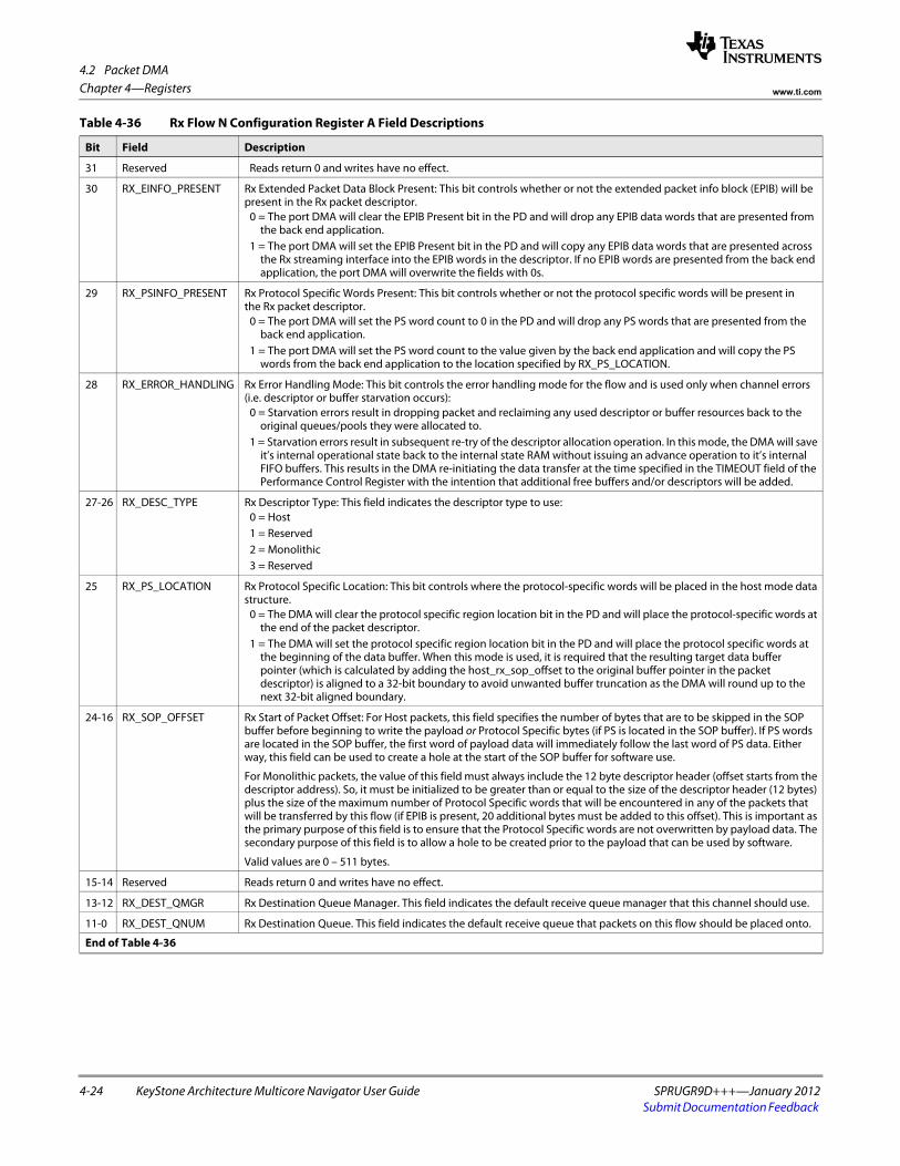
4.2 Packet DMA
4-24 KeyStone Architecture Multicore Navigator User Guide SPRUGR9D+++—January 2012Submit Documentation Feedback
Chapter 4—Registers www.ti.com
Table 4-36 Rx Flow N Configuration Register A Field Descriptions
Bit Field Description
31 Reserved Reads return 0 and writes have no effect.
30 RX_EINFO_PRESENT Rx Extended Packet Data Block Present: This bit controls whether or not the extended packet info block (EPIB) will be present in the Rx packet descriptor.
0 = The port DMA will clear the EPIB Present bit in the PD and will drop any EPIB data words that are presented from the back end application.
1 = The port DMA will set the EPIB Present bit in the PD and will copy any EPIB data words that are presented across the Rx streaming interface into the EPIB words in the descriptor. If no EPIB words are presented from the back end application, the port DMA will overwrite the fields with 0s.
29 RX_PSINFO_PRESENT Rx Protocol Specific Words Present: This bit controls whether or not the protocol specific words will be present in the Rx packet descriptor.
0 = The port DMA will set the PS word count to 0 in the PD and will drop any PS words that are presented from the back end application.
1 = The port DMA will set the PS word count to the value given by the back end application and will copy the PS words from the back end application to the location specified by RX_PS_LOCATION.
28 RX_ERROR_HANDLING Rx Error Handling Mode: This bit controls the error handling mode for the flow and is used only when channel errors (i.e. descriptor or buffer starvation occurs):
0 = Starvation errors result in dropping packet and reclaiming any used descriptor or buffer resources back to the original queues/pools they were allocated to.
1 = Starvation errors result in subsequent re-try of the descriptor allocation operation. In this mode, the DMA will save it’s internal operational state back to the internal state RAM without issuing an advance operation to it’s internal FIFO buffers. This results in the DMA re-initiating the data transfer at the time specified in the TIMEOUT field of the Performance Control Register with the intention that additional free buffers and/or descriptors will be added.
27-26 RX_DESC_TYPE Rx Descriptor Type: This field indicates the descriptor type to use:0 = Host1 = Reserved2 = Monolithic3 = Reserved
25 RX_PS_LOCATION Rx Protocol Specific Location: This bit controls where the protocol-specific words will be placed in the host mode data structure.
0 = The DMA will clear the protocol specific region location bit in the PD and will place the protocol-specific words at the end of the packet descriptor.
1 = The DMA will set the protocol specific region location bit in the PD and will place the protocol specific words at the beginning of the data buffer. When this mode is used, it is required that the resulting target data buffer pointer (which is calculated by adding the host_rx_sop_offset to the original buffer pointer in the packet descriptor) is aligned to a 32-bit boundary to avoid unwanted buffer truncation as the DMA will round up to the next 32-bit aligned boundary.
24-16 RX_SOP_OFFSET Rx Start of Packet Offset: For Host packets, this field specifies the number of bytes that are to be skipped in the SOP buffer before beginning to write the payload or Protocol Specific bytes (if PS is located in the SOP buffer). If PS words are located in the SOP buffer, the first word of payload data will immediately follow the last word of PS data. Either way, this field can be used to create a hole at the start of the SOP buffer for software use.
For Monolithic packets, the value of this field must always include the 12 byte descriptor header (offset starts from the descriptor address). So, it must be initialized to be greater than or equal to the size of the descriptor header (12 bytes) plus the size of the maximum number of Protocol Specific words that will be encountered in any of the packets that will be transferred by this flow (if EPIB is present, 20 additional bytes must be added to this offset). This is important as the primary purpose of this field is to ensure that the Protocol Specific words are not overwritten by payload data. The secondary purpose of this field is to allow a hole to be created prior to the payload that can be used by software.
Valid values are 0 – 511 bytes.
15-14 Reserved Reads return 0 and writes have no effect.
13-12 RX_DEST_QMGR Rx Destination Queue Manager. This field indicates the default receive queue manager that this channel should use.
11-0 RX_DEST_QNUM Rx Destination Queue. This field indicates the default receive queue that packets on this flow should be placed onto.
End of Table 4-36

4.2 Packet DMA
SPRUGR9D+++—January 2012 KeyStone Architecture Multicore Navigator User Guide 4-25Submit Documentation Feedback
Chapter 4—Registerswww.ti.com
4.2.4.2 Rx Flow N Configuration Register B (0x004 + 32×N)The Rx Flow N Configuration Register B contains static configuration information for the Rx DMA flow. The fields in this register can be safely changed only when all of the DMA channels that use this flow have been disabled. The fields in this register are shown in Figure 4-28:
Figure 4-28 Rx Flow N Configuration Register B (0x004 + 32×N)
31 24 23 16 15 8 7 0
RX_SRC_TAG_HI RX_SRC_TAG_LO RX_DEST_TAG_HI RX_DEST_TAG_LO
W-0 W-0 W-0 W-0
Legend: W = Write only; -n = value after reset
Table 4-37 Rx Flow N Configuration Register B Field Descriptions
Bit Field Description
31-24 RX_SRC_TAG_HI Rx Source Tag High Byte Constant Value: This is the value to insert into bits 15-8 of the source tag if the RX_SRC_TAG_HI_SEL is set to 1.
23-16 RX_SRC_TAG_LO Rx Source Tag Low Byte Constant Value: This is the value to insert into bits 7-0 of the source tag if the RX_SRC_TAG_LO_SEL is set to 1.
15-8 RX_DEST_TAG_HI Rx Destination Tag High Byte Constant Value: This is the value to insert into bits 15-8 of the destination tag if the RX_DEST_TAG_HI_SEL is set to 1.
7-0 RX_DEST_TAG_LO Rx Destination Tag Low Byte Constant Value: This is the value to insert into bits 7-0 of the destination tag if the RX_DEST_TAG_LO_SEL is set to 1.
End of Table 4-37

4.2 Packet DMA
4-26 KeyStone Architecture Multicore Navigator User Guide SPRUGR9D+++—January 2012Submit Documentation Feedback
Chapter 4—Registers www.ti.com
4.2.4.3 Rx Flow N Configuration Register C (0x008 + 32×N)The Rx Flow N Configuration Register C contains static configuration information for the Rx DMA flow. The fields in this register can be safely changed only when all of the DMA channels that use this flow have been disabled. The fields in this register are shown in Figure 4-29:
Figure 4-29 Rx Flow N Configuration Register C (0x008 + 32×N)
31 30 28 27 26 24 23 22 20
Reserved RX_SRC_TAG_HI_SEL Reserved RX_SRC_TAG_LO_SEL Reserved RX_DEST_TAG_HI_SEL
R-0 W-0 R-0 W-0 R-0 W-0spacer
19 18 16 15 3 2 0
Reserved RX_DEST_TAG_LO_SEL Reserved RX_SIZE_THRESH_EN
R-0 W-0 R-0 W-0
Legend: R = Read only; W = Write only; -n = value after reset
Table 4-38 Rx Flow N Configuration Register C Field Descriptions (Part 1 of 2)
Bit Field Description
31 Reserved Reads return 0 and writes have no effect.
30-28 RX_SRC_TAG_HI_SEL Rx source tag high byte selector. This field specifies the source for bits 31-24 of the source tag field in the output packet descriptor. This field is encoded as follows:
0 = Do not overwrite1 = Overwrite with value given in RX_SRC_TAG_HI2 = Overwrite with flow_id from back end application3 = Reserved4 = Overwrite with src_tag from back end application5 = Reserved6-7 = Reserved
27 Reserved Reads return 0 and writes have no effect.
26-24 RX_SRC_TAG_LO_SEL Rx source tag low byte selector. This field specifies the source for bits 23-16 of the source tag field in the output packet descriptor. This field is encoded as follows:
0 = Do not overwrite1 = Overwrite with value given in RX_SRC_TAG_LO2 = Overwrite with flow_id from back end application3 = Reserved4 = Overwrite with src_tag from back end application5 = Reserved6-7 = Reserved
23 Reserved Reads return 0 and writes have no effect.
22-20 RX_DEST_TAG_HI_SEL Rx destination tag high byte selector. This field specifies the source for bits 15-8 of the source tag field in the word 1 of the output PD. This field is encoded as follows:
0 = Do not overwrite1 = Overwrite with value given in RX_DEST_TAG_HI2 = Overwrite with flow_id from back end application3 = Reserved4 = Overwrite with dest_tag[7-0] from back end application5 = Overwrite with dest_tag[15-8] from back end application6-7 = Reserved
19 Reserved Reads return 0 and writes have no effect.

4.2 Packet DMA
SPRUGR9D+++—January 2012 KeyStone Architecture Multicore Navigator User Guide 4-27Submit Documentation Feedback
Chapter 4—Registerswww.ti.com
18-16 RX_DEST_TAG_LO_SEL Rx destination tag low byte selector. This field specifies the source for bits 7-0 of the source tag field in word 1 of the output PD. This field is encoded as follows:
0 = Do not overwrite1 = Overwrite with value given in RX_DEST_TAG_LO2 = Overwrite with flow_id from back end application3 = Reserved4 = Overwrite with dest_tag[7-0] from back end application5 = Overwrite with dest_tag[15-8] from back end application6-7 = Reserved
15-3 Reserved Reads return 0 and writes have no effect.
2-0 RX_SIZE_THRESH_EN Rx packet sized based free buffer queue enables. These bits control whether or not the flow will compare the packet size received from the back end application against the RX_SIZE_THRESHN fields to determine which FDQ to allocate the SOP buffer from. Each bit in this field corresponds to 1 of the 3 potential size thresholds that can be compared against. Bit 0 corresponds to RX_SIZE_THRESH0 and bit 2 corresponds to RX_SIZE_THRESH2.
The bits in this field are encoded as follows:0 = Do not use the threshold.1 = Use the thresholds to select between the 4 different potential SOP FDQs.
If thresholds are to be used, the thresholds must be used starting at 0 and progressing to 2. If a single threshold is required, threshold 0 must be used. If 2 thresholds are required, 0 and 1 must be used. It is illegal to enable a higher threshold without enabling the lower thresholds. The following values are valid:
0 - no thresholds enabled.1 - threshold 0 enabled, implies RX_FDQ0_SZ0,1_QNUM,QMGR are used.3 - thresholds 0, 1 enabled, implies RX_FDQ0_SZ0,1,2_QNUM,QMGR are used.7 - thresholds 0, 1, 2 enabled, implies RX_FDQ0_SZ0,1,2,3_QNUM,QMGR are used.
If none of the thresholds are enabled, the DMA controller in the port will allocate the SOP buffer from the queue specified by the RX_FDQ0_SZ0_QMGR and RX_FDQ0_SZ0_QNUM fields. Support for packet size based FDQ selection is optional. If the port does not implement this feature, the bits of this field will be hardcoded to 0 and will not be writable by the host.
End of Table 4-38
Table 4-38 Rx Flow N Configuration Register C Field Descriptions (Part 2 of 2)
Bit Field Description

4.2 Packet DMA
4-28 KeyStone Architecture Multicore Navigator User Guide SPRUGR9D+++—January 2012Submit Documentation Feedback
Chapter 4—Registers www.ti.com
4.2.4.4 Rx Flow N Configuration Register D (0x00C + 32×N)The Rx Flow N Configuration Register D contains static configuration information for the Rx DMA flow. The fields in this register can be safely changed only when all of the DMA channels that use this flow have been disabled. The fields in this register are shown in Figure 4-30:
Figure 4-30 Rx Flow N Configuration Register D (0x00C + 32×N)
31 30 29 28 27 16 15 14 13 12 11 0
Reserved RX_FDQ0_SZ0_QMGR RX_FDQ0_SZ0_QNUM Reserved RX_FDQ1_QMGR RX_FDQ1_QNUM
R-0 W-0 W-0 R-0 W-0 W-0
Legend: R = Read only; W = Write only; -n = value after reset
Table 4-39 Rx Flow N Configuration Register D Field Descriptions
Bit Field Description
31-30 Reserved Reads return 0 and writes have no effect.
29-28 RX_FDQ0_SZ0_QMGR Rx free descriptor 0 queue manager index – size 0. This field specifies which queue manager should be used for the first Rx buffer in a packet whose size is less than or equal to the rx_size0 value. When the size thresholds are not enabled, this is the queue manager for the first Rx buffer.
27-16 RX_FDQ0_SZ0_QNUM Rx free descriptor 0 queue index – size 0. This field specifies which free descriptor queue should be used for the 1st Rx buffer in a packet whose size is less than or equal to the rx_size0 value. When the size thresholds are not enabled, this is the queue number for the first Rx buffer.
15-14 Reserved Reads return 0 and writes have no effect.
13-12 RX_FDQ1_QMGR Rx free descriptor 1 queue manager index. This field specifies which queue manager should be used for the 2nd Rx buffer in a host type packet
11-0 RX_FDQ1_QNUM Rx free descriptor 1 queue index. This field specifies which free descriptor queue should be used for the 2nd Rx buffer in a host type packet
End of Table 4-39
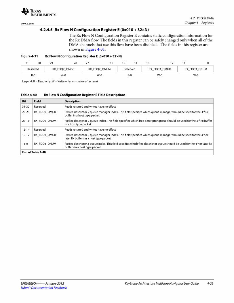
4.2 Packet DMA
SPRUGR9D+++—January 2012 KeyStone Architecture Multicore Navigator User Guide 4-29Submit Documentation Feedback
Chapter 4—Registerswww.ti.com
4.2.4.5 Rx Flow N Configuration Register E (0x010 + 32×N)The Rx Flow N Configuration Register E contains static configuration information for the Rx DMA flow. The fields in this register can be safely changed only when all of the DMA channels that use this flow have been disabled. The fields in this register are shown in Figure 4-31:
Figure 4-31 Rx Flow N Configuration Register E (0x010 + 32×N)
31 30 29 28 27 16 15 14 13 12 11 0
Reserved RX_FDQ2_QMGR RX_FDQ2_QNUM Reserved RX_FDQ3_QMGR RX_FDQ3_QNUM
R-0 W-0 W-0 R-0 W-0 W-0
Legend: R = Read only; W = Write only; -n = value after reset
Table 4-40 Rx Flow N Configuration Register E Field Descriptions
Bit Field Description
31-30 Reserved Reads return 0 and writes have no effect.
29-28 RX_FDQ2_QMGR Rx free descriptor 2 queue manager index. This field specifies which queue manager should be used for the 3rd Rx buffer in a host type packet
27-16 RX_FDQ2_QNUM Rx free descriptor 2 queue index. This field specifies which free descriptor queue should be used for the 3rd Rx buffer in a host type packet
15-14 Reserved Reads return 0 and writes have no effect.
13-12 RX_FDQ3_QMGR Rx free descriptor 3 queue manager index. This field specifies which queue manager should be used for the 4th or later Rx buffers in a host type packet
11-0 RX_FDQ3_QNUM Rx free descriptor 3 queue index. This field specifies which free descriptor queue should be used for the 4th or later Rx buffers in a host type packet
End of Table 4-40

4.2 Packet DMA
4-30 KeyStone Architecture Multicore Navigator User Guide SPRUGR9D+++—January 2012Submit Documentation Feedback
Chapter 4—Registers www.ti.com
4.2.4.6 Rx Flow N Configuration Register F (0x014 + 32×N)The Rx Flow N Configuration Register F contains static configuration information for the Rx DMA flow. The fields in this register can be safely changed only when all of the DMA channels that use this flow have been disabled. This register is optional. The fields in this register are shown in Figure 4-32:
Figure 4-32 Rx Flow N Configuration Register F (0x014 + 32×N)
31 16 15 0
RX_SIZE_THRESH0 RX_SIZE_THRESH1
W-0 W-0
Legend: W = Write only; -n = value after reset
Table 4-41 Rx Flow N Configuration Register F Field Descriptions
Bit Field Description
31-16 RX_SIZE_THRESH0 Rx packet size threshold 0. This value is left-shifted by 5 bits and compared against the packet size to determine which free descriptor queue should be used for the SOP buffer in the packet. If the packet size is less than or equal to the value given in this threshold, the DMA controller in the port will allocate the SOP buffer from the queue given by the RX_FDQ0_SZ0_QMGR and RX_FDQ0_SZ0_QNUM fields.
This field is optional.
15-0 RX_SIZE_THRESH1 Rx packet size threshold 1. This value is left-shifted by 5 bits and compared against the packet size to determine which free descriptor queue should be used for the SOP buffer in the packet. If the packet size is greater than the RX_SIZE_THRESH0 but is less than or equal to the value given in this threshold, the DMA controller in the port will allocate the SOP buffer from the queue given by the RX_FDQ0_SZ1_QMGR and RX_FDQ0_SZ1_QNUM fields. If enabled, this value must be greater than the value given in the RX_SIZE_THRESH0 field.
This field is optional.
End of Table 4-41
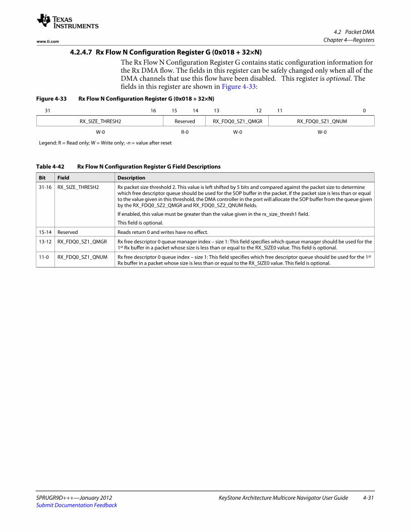
4.2 Packet DMA
SPRUGR9D+++—January 2012 KeyStone Architecture Multicore Navigator User Guide 4-31Submit Documentation Feedback
Chapter 4—Registerswww.ti.com
4.2.4.7 Rx Flow N Configuration Register G (0x018 + 32×N)The Rx Flow N Configuration Register G contains static configuration information for the Rx DMA flow. The fields in this register can be safely changed only when all of the DMA channels that use this flow have been disabled. This register is optional. The fields in this register are shown in Figure 4-33:
Figure 4-33 Rx Flow N Configuration Register G (0x018 + 32×N)
31 16 15 14 13 12 11 0
RX_SIZE_THRESH2 Reserved RX_FDQ0_SZ1_QMGR RX_FDQ0_SZ1_QNUM
W-0 R-0 W-0 W-0
Legend: R = Read only; W = Write only; -n = value after reset
Table 4-42 Rx Flow N Configuration Register G Field Descriptions
Bit Field Description
31-16 RX_SIZE_THRESH2 Rx packet size threshold 2. This value is left shifted by 5 bits and compared against the packet size to determine which free descriptor queue should be used for the SOP buffer in the packet. If the packet size is less than or equal to the value given in this threshold, the DMA controller in the port will allocate the SOP buffer from the queue given by the RX_FDQ0_SZ2_QMGR and RX_FDQ0_SZ2_QNUM fields.
If enabled, this value must be greater than the value given in the rx_size_thresh1 field.
This field is optional.
15-14 Reserved Reads return 0 and writes have no effect.
13-12 RX_FDQ0_SZ1_QMGR Rx free descriptor 0 queue manager index – size 1: This field specifies which queue manager should be used for the 1st Rx buffer in a packet whose size is less than or equal to the RX_SIZE0 value. This field is optional.
11-0 RX_FDQ0_SZ1_QNUM Rx free descriptor 0 queue index – size 1: This field specifies which free descriptor queue should be used for the 1st Rx buffer in a packet whose size is less than or equal to the RX_SIZE0 value. This field is optional.

4.2 Packet DMA
4-32 KeyStone Architecture Multicore Navigator User Guide SPRUGR9D+++—January 2012Submit Documentation Feedback
Chapter 4—Registers www.ti.com
4.2.4.8 Rx Flow N Configuration Register H (0x01C + 32×N)The Rx Flow N Configuration Register H contains static configuration information for the Rx DMA flow. The fields in this register can be safely changed only when all of the DMA channels that use this flow have been disabled. This register is optional. The fields in this register are shown in Figure 4-34:
Figure 4-34 Rx Flow N Configuration Register H (0x01C + 32×N)
31 30 29 28 27 16 15 14 13 12 11 0
Reserved RX_FDQ0_SZ2_QMGR RX_FDQ0_SZ2_QNUM Reserved RX_FDQ0_SZ3_QMGR RX_FDQ0_SZ3_QNUM
R-0 W-0 W-0 R-0 W-0 W-0
Legend: R = Read only; W = Write only; -n = value after reset
Table 4-43 Rx Flow N Configuration Register H Field Descriptions
Bit Field Description
31-30 Reserved Reads return 0 and writes have no effect.
29-28 RX_FDQ0_SZ2_QMGR Rx free descriptor 0 queue manager index – size 2. This field specifies which queue manager should be used for the 1st Rx buffer in a packet whose size is less than or equal to the rx_size2 value. This field is optional.
27-16 RX_FDQ0_SZ2_QNUM Rx Free descriptor 0 queue index – size 2. This field specifies which Free Descriptor Queue should be used for the 1st Rx buffer in a packet whose size is less than or equal to the rx_size2 value. This field is optional.
15-14 Reserved Reads return 0 and writes have no effect.
13-12 RX_FDQ0_SZ3_QMGR Rx free descriptor 0 queue manager index – size 3. This field specifies which queue manager should be used for the 1st Rx buffer in a packet whose size was not less than or equal to the rx_size3 value. This field is optional. This queue manager is selected if the packet length does not match any enabled size threshold.
11-0 RX_FDQ0_SZ3_QNUM Rx free descriptor 0 queue index – size 3. This field specifies which free descriptor queue should be used for the 1st Rx buffer in a packet whose size is less than or equal to the rx_size3 value. This field is optional. This queue number is selected if the packet length does not match any enabled size threshold.

4.2 Packet DMA
SPRUGR9D+++—January 2012 KeyStone Architecture Multicore Navigator User Guide 4-33Submit Documentation Feedback
Chapter 4—Registerswww.ti.com
4.2.5 Tx Scheduler Configuration RegionThis region provides registers to configure the priority of Tx channels. The Tx DMA selects channels using a four level round robin approach. The memory map for the Tx DMA Scheduler Configuration registers region is shown in Table 4-44:
4.2.5.1 Tx Channel N Scheduler Configuration Register (0x000 + 4×N)The Tx Channel N Scheduler Configuration Register contains static configuration information that affects the conditions under which each channel will be given an opportunity to use the Tx DMA unit(s). The fields in this register are shown in Figure 4-35:
Table 4-44 Tx DMA Scheduler Configuration Region Registers
Address Register
0x000 Tx Channel 0 Scheduler Configuration Register
0x004 Tx Channel 1 Scheduler Configuration Register
. . . . . .
0x0 + N×4 Tx Channel N Scheduler Configuration Register
End of Table 4-44
Figure 4-35 Tx Channel N Scheduler Configuration Register (0x000 + 4×N)
31 2 1 0
Reserved PRIORITY
R-0 R/W-0
Legend: R = Read only; R/W = Read/Write; -n = value after reset
Table 4-45 Tx Channel N Scheduler Configuration Register Field Descriptions
Bit Field Description
31-2 Reserved Reads return 0 and writes have no effect.
1-0 PRIORITY Tx scheduling priority. These bits select which scheduling bin the channel will be placed in for bandwidth allocation of the Tx DMA units. This field is encoded as follows:
0 = High priority1 = Medium – high priority2 = Medium – low priority3 = Low priority
Arbitration between bins is performed in a strict priority fashion. High priority channels will always be serviced first. If no high priority channels are requesting then all medium-high priority channels will be serviced next. If no high priority or medium-high priority channels are requesting then all medium-low priority channels will be serviced next. When no other channels are requesting, the low priority channels will be serviced.
All channels within a given bin are serviced in a round robin order. Only channels that are enabled and that have sufficient free space in their per channel FIFO will be included in the round robin arbitration.
End of Table 4-45

4.3 QMSS PDSPs
4-34 KeyStone Architecture Multicore Navigator User Guide SPRUGR9D+++—January 2012Submit Documentation Feedback
Chapter 4—Registers www.ti.com
4.3 QMSS PDSPsThe queue manager sub system contains two or eight packed data structure processors (PDSP) and associated hardware that allow autonomous QMSS-related tasks with interrupt notification. PDSPs are normally loaded with firmware during configuration, then programmed with firmware-specific commands. Because the interrupt distributors service pairs of PDSPs, most firmware images can be loaded on even or odd PDSPs, with restrictions usually due to conflicts with interrupt usage. For example, using Acc48 on PDSP1 and PDSP5 would cause both instances to drive the same interrupts on INTD1. If Acc48 is loaded on PDSP1, it can also be loaded on PDSP3 or PDSP7.The firmware builds provided in the PDK come in several varieties in both big- and little-endian formats. Three types of firmware are provided:
• Descriptor accumulator firmware that monitors programmed queues, pops descriptors found there and interrupts the host with a list of descriptor addresses (this firmware comes in 16, 32, and 48 channel builds)
• Quality of service firmware that monitors all packet flows in the system, and verifies that neither the peripherals nor the host CPU are overwhelmed with packets
• Navigator runtime firmware that provides dynamic load balancing of CorePacs.
Table 4-46 shows which PDSP may be used for each firmware type, though several combinations will not work due to conflicts. Table 4-47 lists several configurations that avoid conflicts.Table 4-46 Possible PDSP Firmware Loading
PDSP 1 PDSP 2 PDSP 3 PDSP 4 PDSP 5 PDSP 6 PDSP 7 PDSP 8
INTD 1 INTD 2 INTD 1 INTD 2
Acc 48 Acc 48 Acc 48 Acc 48
QoS QoS QoS QoS
Acc 32 Acc 32 Acc 32 Acc 32
Acc 16 Acc 16 Acc 16 Acc 16
NRT1 NRT2 NRT1 NRT2 NRT1 NRT2 NRT1 NRT2
End of Table 4-46
Table 4-47 Recommended PDSP Firmware Loading
PDSP 1 PDSP 2 PDSP 3 PDSP 4 PDSP 5 PDSP 6 PDSP 7 PDSP 8
INTD 1 INTD 2 INTD 1 INTD 2
Acc 48 Acc 48 NRT1 QoS NRT1 QoS
Acc 48 QoS Acc 48 NRT1 QoS
Acc 48 QoS Acc 32 Acc 16 NRT1 NRT2 NRT1 NRT2
Acc 48 QoS NRT1 NRT2 NRT1 NRT2 NRT1 NRT2
Acc 32 Acc 16 Acc 32 Acc 16 NRT1 QoS NRT1 QoS
Acc 32 Acc 16 Acc 32 Acc 16 NRT1 QoS
Acc 32 Acc 16 Acc 32 Acc 16 NRT1 NRT2 NRT1 NRT2
Acc 32 Acc 16 NRT1 NRT2 NRT1 NRT2 NRT1 NRT2
NRT1 NRT2 NRT1 NRT2 NRT1 NRT2 NRT1 NRT2
End of Table 4-47

4.3 QMSS PDSPs
SPRUGR9D+++—January 2012 KeyStone Architecture Multicore Navigator User Guide 4-35Submit Documentation Feedback
Chapter 4—Registerswww.ti.com
4.3.1 Descriptor Accumulation Firmware
For accumulation purposes, the firmware will read the queue status RAM to obtain status information on the programmed queues. So the host software must program the Queue N Status and Configuration Register D registers with the value 0x81 for every queue that is to be examined by the firmware. This will cause the status bit in the queue status RAM to be set while the queue is not empty, and clear when empty.
The 32-channel version provides 32 high channels - i.e. channels 0 to 31 that are serviced once per iteration through the channels. The 16-channel firmware provides 16 channels (0...15) that are also scanned as fast as possible (e.g. high), yet these trigger the low priority interrupts. In this way, the 16- and 32-channel accumulators may be used together without interrupt interference. The 48-channel version provides channels 0 to 31 that are high, and channels 32 to 47 that are low — serviced one at a time through each iteration through channels 0 to 31. Note that any channel in any version of the firmware may be configured to monitor 32 contiguous queues, not just the low priority channels.
The accumulator is programmed using a 20-byte shared memory command buffer. The command buffer consists of a command word, followed by several parameters. The process of writing a command is to check to see if the command buffer is free, then write the command parameters, and finally write the command. Optionally, the calling program can wait for command completion.
The command buffer is free when the command field is set to 0x00.
When a command is written, the host CPU must write the word containing the command byte last. The command byte is written with bit 7 set to signify a command to the PDSP. The command buffer is in internal RAM and should not be marked as cacheable by the host CPU. If the RAM is cached on the host CPU, then the host must perform two separate writes and cache flushes; the first for writing the parameters, and then a second independent write and cache flush for writing the command word. All writes should be performed as 32 bit quantities.
Once the command is written, the PDSP will clear the command field upon command completion. The command results can then be read from the return code field. Note that the PDSP must be enabled before the firmware can be programmed.
4.3.1.1 Command Buffer InterfaceThe single queue channels are high priority channels that monitor a single queue. The format of the command is shown in Table 4-48:
Table 4-48 Command Buffer Format
Command Buffer Offset
Field
Byte 3 Byte 2 Byte 1 Byte 0
0x00 Return code 0 Command Channel (0-47)
0x04 Queue enable mask
0x08 List buffer physical address
0x0C Max page entries Queue number
0x10 0 Configuration Timer load count
End of Table 4-48

4.3 QMSS PDSPs
4-36 KeyStone Architecture Multicore Navigator User Guide SPRUGR9D+++—January 2012Submit Documentation Feedback
Chapter 4—Registers www.ti.com
Table 4-49 shows the breakdown of each field:
Table 4-49 Command Buffer Field Descriptions
Field Byte Width Notes
Channel Number 1 Accumulator channel affected (0-47)
Command 1 Channel command0x80 = Disable channel 0x81 = Enable channel0x82 = Global timer command (see Table 4-51)0x83 = Reclamation queue command channel (see Table 4-52)0x84 = Queue Diversion command (see )
Return Code 1 Command return code from the firmware:0 = Idle (initial) state1 = Success2 = Invalid command3 = Invalid channel4 = Channel is not active5 = Channel already active6 = Invalid queue number
Queue Enable Mask 4 This field specifies which queues are to be included in the queue group. Bit 0 corresponds to the base queue index, and bit 31 corresponds to the base queue index plus 31. For any bit set in this mask, the corresponding queue index is included in the monitoring function.
This field is ignored in single-queue mode.
List Address 4 Physical pointer to list ping/pong buffer
NULL when channel disabled
QueueNumber 2 Queue number to monitor. In multi-queue mode this serves as the first of 32 consecutive queues, and must be a multiple of 32. Queue numbers programmed into the firmware must always be physical queue numbers, not a PKTDMA’s logical queue mapping.
Max Page Entries 2 Max entries per list buffer page, including the count or NULL entry. For example, if you wish your list to contain 20 descriptor entries, set this field to 21. The memory required for the list would then be 21 times 2 (ping/pong) times the List Entry Size (4, 8, or 16 bytes).
Timer Load Count 2 Count of global timer ticks to delay interrupt. This count acts as a countdown, except when the list is full or this count = 0, which causes an immediate interrupt. The total delay is the time programmed into the global timer (see Table 4-51) times this count. This field is not used when the Interrupt Pacing Mode = None.
Configuration 1 Configuration byte (see Table 4-50)
End of Table 4-49

4.3 QMSS PDSPs
SPRUGR9D+++—January 2012 KeyStone Architecture Multicore Navigator User Guide 4-37Submit Documentation Feedback
Chapter 4—Registerswww.ti.com
The configuration byte contains several sub-fields as detailed in Table 4-50:
4.3.1.2 Global Timer Command InterfaceThe global timer value used by the PDSP may be programmed using the format shown in Table 4-51. This timer has a programmable count based on the sub-system clock. When this count expires, a local tick is registered in the firmware. The tick is used when timing channel interrupts based on the Timer Load Count value supplied in the channel configuration.
The value of Timer Constant is the number of queue manager sub-system clocks divided by 2 that comprise a single tick in the accumulator firmware.
For example, if the sub-system clock is 350 MHz (the default), and the desired firmware tick is 20 μs, the proper timer constant for this command is computed as follows:
Timer constant = (350,000,000 cycles/sec) × (0.000020 sec) / (2 cycles) = 3,500
The firmware initializes with a default timer constant value of 4375 (25 μs).
Table 4-50 Configuration Byte Subfields
Bits Field Name Notes
7-6 Reserved Reads return 0 and writes have no effect.
5 Multi-Queue Mode 0 = Single queue mode — the channel monitors a single queue.1 = Multi-queue mode — the channel monitors up to 32 queues starting at the supplied base queue index.
4 List Count Mode 0 = NULL terminate mode — the last list entry is used to store a NULL pointer record (NULL terminator) to mark the end of list.
1 = Entry count mode — the first list entry is used to store the total list entry count (not including the length entry).
3-2 List Entry Size 0 = D register only (4 byte entries)1 = C, D registers (8 byte entries)2 = A, B, C, D registers (16 byte entries)
• Note: For Lo-Priority, when register C is extracted, the firmware will OR the index of the queue number into the upper 16 bits. This is so the original queue can be identified. Example: If the base queue number is 32, a value of 0 (in the upper 16 bits) equals queue 32, 1 = 33, ... 31 = 63.
1-0 Interrupt Pacing Mode 0 = None — interrupt on entry threshold count only (i.e. list full)1 = Time delay since last interrupt. This produces a periodic interrupt (as long as the list does not fill early and
descriptors continue arriving).2 = Time delay since first new packet. This starts the timer countdown with the first packet received following a
previous interrupt.3 = Time delay since last new packet. This restarts the timer countdown with each new packet.
End of Table 4-50
Table 4-51 Global Timer Command Format
Command Buffer Offset
Field
Byte 3 Byte 2 Byte 1 Byte 0
0x00 Return code 0 0x82 0
0x04 0 Timer Constant
End of Table 4-51

4.3 QMSS PDSPs
4-38 KeyStone Architecture Multicore Navigator User Guide SPRUGR9D+++—January 2012Submit Documentation Feedback
Chapter 4—Registers www.ti.com
4.3.1.3 Reclamation Queue Command InterfaceThe Accumulator firmware includes an optional reclamation queue that can be used for packet discards. Any descriptor placed on the reclamation queue will be recycled in the same manner as if it had been submitted to a Tx PKTDMA. The descriptor packet information word is used to determine the return queue and the return handling, including options to unlink host descriptors and push to either the front or the back of the return queue.
Note—PDSP firmware and the queue manager do not know how a PKTDMA has mapped logical queues to the physical queue manager. The physical queue number should always be used here. When reading descriptors, the firmware will append qmgr:qnum fields together to determine the physical queue.
Setting the reclamation queue to 0 disables all reclamation queue monitoring. The firmware initializes with a default reclamation queue of 0 (disabled).
This command always returns 1 for success in the return code.
4.3.1.4 Queue Diversion Command InterfaceThe Accumulator firmware includes an optional queue diversion queue that can be used to remotely cause a queue diversion. This is used by the PDSP firmware to allow access to queue diversion. When enabled, any descriptor placed on the diversion queue will be popped, and its Timestamp Info field (word 0 of EPIB block) will be written to the QM diversion register. The descriptor pointer will then be pushed onto the diversion completion queue. It is an error to push a descriptor to the diversion queue without a valid EPIB configuration.
Setting the diversion queue to 0 disables diversion queue monitoring. The firmware initializes with a default diversion queue of 0 (disabled).
This command always returns 1 for success in the return code.
Table 4-52 Reclamation Queue Command Format
Command Buffer Offset
Field
Byte 3 Byte 2 Byte 1 Byte 0
0x00 Return code 0 0x83 0
0x04 0 Queue number
End of Table 4-52
Table 4-53 Queue Diversion Command Format
Command Buffer Offset
Field
Byte 3 Byte 2 Byte 1 Byte 0
0x00 Return code 0 0x84 0
0x04 Queue number of Diversion Completion Queue Queue number of Diversion Queue
End of Table 4-53
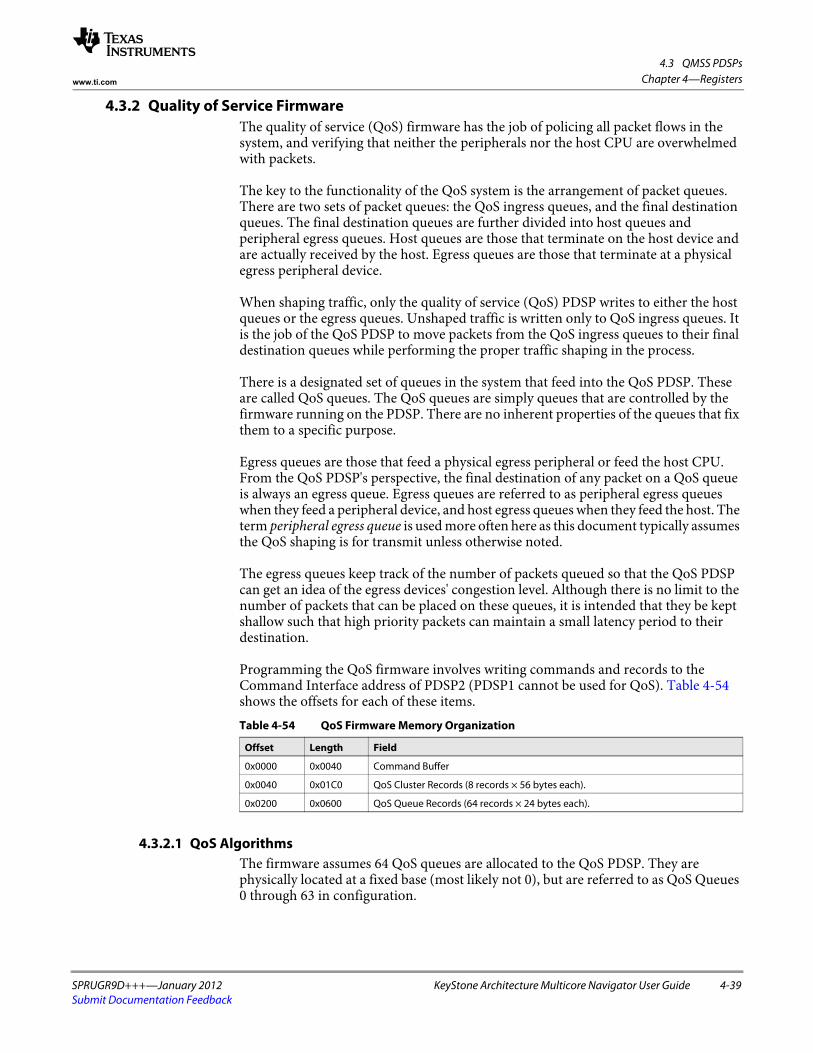
4.3 QMSS PDSPs
SPRUGR9D+++—January 2012 KeyStone Architecture Multicore Navigator User Guide 4-39Submit Documentation Feedback
Chapter 4—Registerswww.ti.com
4.3.2 Quality of Service FirmwareThe quality of service (QoS) firmware has the job of policing all packet flows in the system, and verifying that neither the peripherals nor the host CPU are overwhelmed with packets.
The key to the functionality of the QoS system is the arrangement of packet queues. There are two sets of packet queues: the QoS ingress queues, and the final destination queues. The final destination queues are further divided into host queues and peripheral egress queues. Host queues are those that terminate on the host device and are actually received by the host. Egress queues are those that terminate at a physical egress peripheral device.
When shaping traffic, only the quality of service (QoS) PDSP writes to either the host queues or the egress queues. Unshaped traffic is written only to QoS ingress queues. It is the job of the QoS PDSP to move packets from the QoS ingress queues to their final destination queues while performing the proper traffic shaping in the process.
There is a designated set of queues in the system that feed into the QoS PDSP. These are called QoS queues. The QoS queues are simply queues that are controlled by the firmware running on the PDSP. There are no inherent properties of the queues that fix them to a specific purpose.
Egress queues are those that feed a physical egress peripheral or feed the host CPU. From the QoS PDSP's perspective, the final destination of any packet on a QoS queue is always an egress queue. Egress queues are referred to as peripheral egress queues when they feed a peripheral device, and host egress queues when they feed the host. The term peripheral egress queue is used more often here as this document typically assumes the QoS shaping is for transmit unless otherwise noted.
The egress queues keep track of the number of packets queued so that the QoS PDSP can get an idea of the egress devices' congestion level. Although there is no limit to the number of packets that can be placed on these queues, it is intended that they be kept shallow such that high priority packets can maintain a small latency period to their destination.
Programming the QoS firmware involves writing commands and records to the Command Interface address of PDSP2 (PDSP1 cannot be used for QoS). Table 4-54 shows the offsets for each of these items.
4.3.2.1 QoS AlgorithmsThe firmware assumes 64 QoS queues are allocated to the QoS PDSP. They are physically located at a fixed base (most likely not 0), but are referred to as QoS Queues 0 through 63 in configuration.
Table 4-54 QoS Firmware Memory Organization
Offset Length Field
0x0000 0x0040 Command Buffer
0x0040 0x01C0 QoS Cluster Records (8 records × 56 bytes each).
0x0200 0x0600 QoS Queue Records (64 records × 24 bytes each).

4.3 QMSS PDSPs
4-40 KeyStone Architecture Multicore Navigator User Guide SPRUGR9D+++—January 2012Submit Documentation Feedback
Chapter 4—Registers www.ti.com
A QoS queue is a rate- and congestion-controlled channel that feeds into a single egress queue. Multiple QoS queues can merge onto a single egress queue, but each individual QoS queue may have only one destination.
The QoS firmware is designed around the idea that multiple QoS queues are grouped together to provide multiple flows and priorities to a single egress device. A group of QoS queues with a common egress device queue is called a QoS queue cluster (or QoS cluster).
A QoS cluster is created through the host software by first initializing the individual QoS queues used in the cluster, and then creating a QoS cluster that encompasses the queues in question. Different QoS algorithms can be executed on individual QoS clusters.
4.3.2.1.1 Modified Token Bucket Algorithm
Basic Operation The modified token bucket algorithm allows each queue in a cluster to be assigned a fixed rate in bytes per time iteration (typically 25 μs, but is configurable). This is called iteration credit. In addition, there is a maximum number of bytes that can be retained as credit against a future traffic burst. This retained credit is called total credit. The maximum limit is called maximum credit.
Iteration credit is added to a queue's total credit at the start of each sampling period. While total credit remains above 0, the packet waiting at the head of the QoS queue is examined for size. If the byte size of the packet is less than or equal to the queue's total credit, the packet is forwarded and the packet byte size is deducted from the credit bytes. The queue's unused credit is carried over to the next iteration (held in its total credit), up to the maximum amount allocated to the queue.
For example, if a flow is rated for 40Mb/s, but can burst up to 20,000 bytes at a time, the queue would be configured as follows on a system with a 25-μs iteration:
• Iteration Credit = 125 bytes (40 Mb/s is 125 bytes every 25 μs)• Maximum Credit = 20,000 bytes
The sum total of iteration credit for all queues in the cluster should add up to the total expected data rate of the egress device. When configuring a cluster, it is important that this rule be followed.
Global Credit and Borrowing After all packets have been transmitted from a QoS queue, the queue's remaining total credit can not exceed the maximum credit allocated to that queue. Any credit bytes above the maximum credit limit are added to a global credit sum, and the total credit is set to the maximum credit.
Any queue may borrow from the global credit pool when doing so allows the queue to transmit an additional packet or is used to fill its allotted maximum credit level. This is done on a first come, first served basis. The global credit system allows queues that are allocated less credit than necessary to saturate a device to make use of the additional bandwidth when it is not being used by the other QoS queues in the cluster.
Thus in the example above, the queue was set to 40 Mb/s can use the entire bandwidth of the egress device when the other cluster queues are idle.
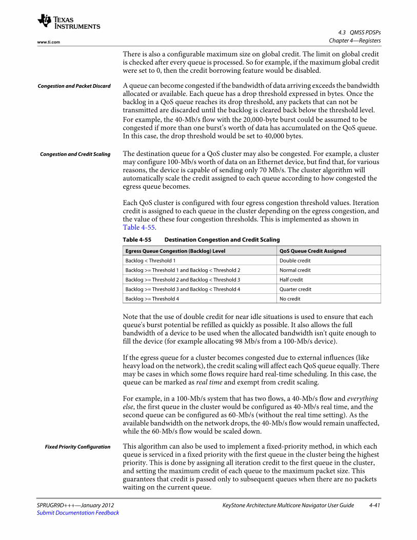
4.3 QMSS PDSPs
SPRUGR9D+++—January 2012 KeyStone Architecture Multicore Navigator User Guide 4-41Submit Documentation Feedback
Chapter 4—Registerswww.ti.com
There is also a configurable maximum size on global credit. The limit on global credit is checked after every queue is processed. So for example, if the maximum global credit were set to 0, then the credit borrowing feature would be disabled.
Congestion and Packet Discard A queue can become congested if the bandwidth of data arriving exceeds the bandwidth allocated or available. Each queue has a drop threshold expressed in bytes. Once the backlog in a QoS queue reaches its drop threshold, any packets that can not be transmitted are discarded until the backlog is cleared back below the threshold level.For example, the 40-Mb/s flow with the 20,000-byte burst could be assumed to be congested if more than one burst’s worth of data has accumulated on the QoS queue. In this case, the drop threshold would be set to 40,000 bytes.
Congestion and Credit Scaling The destination queue for a QoS cluster may also be congested. For example, a cluster may configure 100-Mb/s worth of data on an Ethernet device, but find that, for various reasons, the device is capable of sending only 70 Mb/s. The cluster algorithm will automatically scale the credit assigned to each queue according to how congested the egress queue becomes.
Each QoS cluster is configured with four egress congestion threshold values. Iteration credit is assigned to each queue in the cluster depending on the egress congestion, and the value of these four congestion thresholds. This is implemented as shown in Table 4-55.
Note that the use of double credit for near idle situations is used to ensure that each queue's burst potential be refilled as quickly as possible. It also allows the full bandwidth of a device to be used when the allocated bandwidth isn't quite enough to fill the device (for example allocating 98 Mb/s from a 100-Mb/s device).
If the egress queue for a cluster becomes congested due to external influences (like heavy load on the network), the credit scaling will affect each QoS queue equally. There may be cases in which some flows require hard real-time scheduling. In this case, the queue can be marked as real time and exempt from credit scaling.
For example, in a 100-Mb/s system that has two flows, a 40-Mb/s flow and everything else, the first queue in the cluster would be configured as 40-Mb/s real time, and the second queue can be configured as 60-Mb/s (without the real time setting). As the available bandwidth on the network drops, the 40-Mb/s flow would remain unaffected, while the 60-Mb/s flow would be scaled down.
Fixed Priority Configuration This algorithm can also be used to implement a fixed-priority method, in which each queue is serviced in a fixed priority with the first queue in the cluster being the highest priority. This is done by assigning all iteration credit to the first queue in the cluster, and setting the maximum credit of each queue to the maximum packet size. This guarantees that credit is passed only to subsequent queues when there are no packets waiting on the current queue.
Table 4-55 Destination Congestion and Credit Scaling
Egress Queue Congestion (Backlog) Level QoS Queue Credit Assigned
Backlog < Threshold 1 Double credit
Backlog >= Threshold 1 and Backlog < Threshold 2 Normal credit
Backlog >= Threshold 2 and Backlog < Threshold 3 Half credit
Backlog >= Threshold 3 and Backlog < Threshold 4 Quarter credit
Backlog >= Threshold 4 No credit

4.3 QMSS PDSPs
4-42 KeyStone Architecture Multicore Navigator User Guide SPRUGR9D+++—January 2012Submit Documentation Feedback
Chapter 4—Registers www.ti.com
For example, assume there are three queues, A, B, and C. In a simple priority system, queue A would always transmit packets when packets are available, while queue B transmits only when queue A is idle, and queue C transmits only when queue B is idle.
On a 100-Mb/s system, the queues could be configured as follows:• Queue A
– Iteration Credit = 313 (100 Mb/s is 312.5 bytes every 25 μs)– Max Credit = 1514
• Queue B– Iteration Credit = 0– Max Credit = 1514
• Queue C– Iteration Credit = 0– Max Credit = 1514
The way the algorithm works, queue A will get 313 bytes of credit at the start of each iteration. Because queue A can hold up to 1514 bytes as max credit, queue A will never pass credit onto queue B while queue A has a packet. (If queue A has more than 1514 bytes of credit, it can always forward a packet.)
Queue A must be idle for an entire packet time (1514 bytes of iteration credit) before any credit will start flowing into queue B. The same relationship holds between queue B and queue C. The only way queue B sends a packet is after queue A is idle for a packet time, and the only way queue C can send a packet is after queue B is idle for a packet time.
4.3.2.2 Command Buffer InterfaceThe process of writing a command is to check to see if the command buffer is free, then write the command parameters, and finally write the command. Optionally, the caller can wait for command completion.
The command buffer is free when the command field of the first work in the command buffer is set to 0x00.
When a command is written, the host CPU must write the word containing the command byte last. The command buffer is in internal RAM and should not be marked as cacheable by the host CPU. If the RAM is cached on the host CPU, then the host must perform two separate writes and cache flushes; the first for writing the parameters, and then a second independent write and cache flush for writing the command word. All writes should be performed as 32-bit quantities.
Note that the first word of the command buffer appears in a non-contiguous memory region as the remaining fields in the buffer.
After the command is written, the PDSP will clear the command field upon command completion. The command results can then be read from the Return Code field.
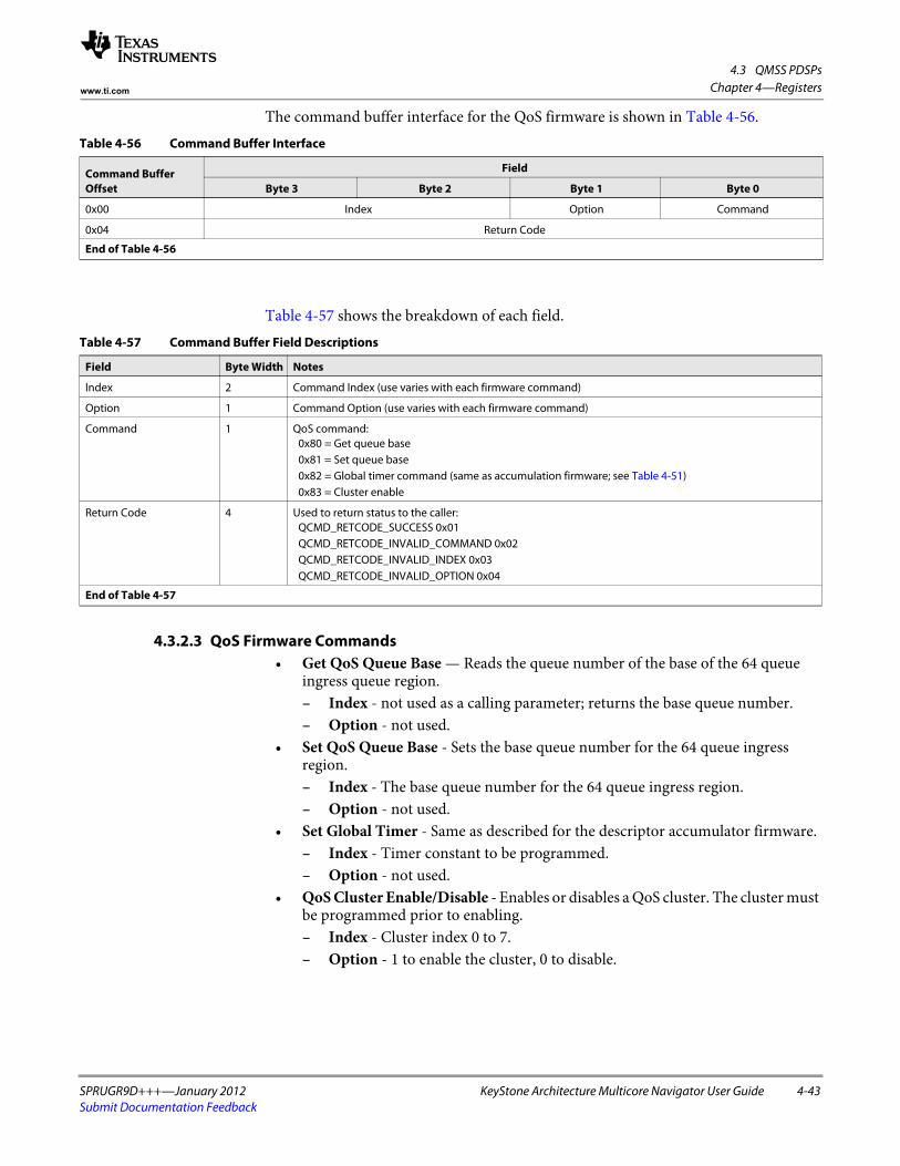
4.3 QMSS PDSPs
SPRUGR9D+++—January 2012 KeyStone Architecture Multicore Navigator User Guide 4-43Submit Documentation Feedback
Chapter 4—Registerswww.ti.com
The command buffer interface for the QoS firmware is shown in Table 4-56.
Table 4-57 shows the breakdown of each field.
4.3.2.3 QoS Firmware Commands• Get QoS Queue Base — Reads the queue number of the base of the 64 queue
ingress queue region.– Index - not used as a calling parameter; returns the base queue number.– Option - not used.
• Set QoS Queue Base - Sets the base queue number for the 64 queue ingress region.– Index - The base queue number for the 64 queue ingress region.– Option - not used.
• Set Global Timer - Same as described for the descriptor accumulator firmware.– Index - Timer constant to be programmed.– Option - not used.
• QoS Cluster Enable/Disable - Enables or disables a QoS cluster. The cluster must be programmed prior to enabling.– Index - Cluster index 0 to 7.– Option - 1 to enable the cluster, 0 to disable.
Table 4-56 Command Buffer Interface
Command Buffer Offset
Field
Byte 3 Byte 2 Byte 1 Byte 0
0x00 Index Option Command
0x04 Return Code
End of Table 4-56
Table 4-57 Command Buffer Field Descriptions
Field Byte Width Notes
Index 2 Command Index (use varies with each firmware command)
Option 1 Command Option (use varies with each firmware command)
Command 1 QoS command:0x80 = Get queue base0x81 = Set queue base0x82 = Global timer command (same as accumulation firmware; see Table 4-51)0x83 = Cluster enable
Return Code 4 Used to return status to the caller:QCMD_RETCODE_SUCCESS 0x01QCMD_RETCODE_INVALID_COMMAND 0x02QCMD_RETCODE_INVALID_INDEX 0x03QCMD_RETCODE_INVALID_OPTION 0x04
End of Table 4-57

4.3 QMSS PDSPs
4-44 KeyStone Architecture Multicore Navigator User Guide SPRUGR9D+++—January 2012Submit Documentation Feedback
Chapter 4—Registers www.ti.com
4.3.2.4 QoS Queue RecordThe basic building block of the QoS system is a QoS queue. Each queue represents a flow priority, flow rate, drop policy, and egress queue. (Different QoS algorithms may or may not make use of all these properties.) Queues with the same egress queue are grouped together into a queue cluster called a QoS cluster. A cluster can contain from one to nine QoS queues. Any of the 64 available QoS queues can be allocated into any given QoS cluster, although a queue may not belong to more than one cluster.
The QoS Queue Record format is shown in Table 4-58:
Table 4-59 shows the breakdown of each field:
4.3.2.5 QoS Cluster RecordThe QoS cluster controls the order of how QoS Queues are processed, and tracks properties of all QoS Queues, like global credit and egress queue congestion. The format of the record is shown in Table 4-60.
Table 4-58 QoS Queue Record
QoS Queue Offset
Field
Byte 3 Byte 2 Byte 1 Byte 0
0x00 Iteration Credit Egress Queue
0x04 Total Credit
0x08 Maximum Credit
0x0C Congestion Threshold
0x10 Packets Forwarded
0x14 Packets Dropped
End of Table 4-58
Table 4-59 QoS Queue Field Descriptions
Field Byte Width Notes
Egress Queue 2 The Queue number of the forwarding queue.
Iteration Credit 2 The amount of forwarding byte credit that the queue receives every 25 μs.
Total Credit 4 The total amount of forwarding byte credit the that queue is currently holding.
Maximum Credit 4 The maximum amount of forwarding byte credit that the queue is allowed to hold at the end of the timer iteration. Any credit over the maximum limit is added to a global pool.
Congestion Threshold 4 The size in bytes at which point the QoS queue is considered to be congested.
Packets Forwarded 4 The number of packets forwarded to the Egress Queue.
Packets Dropped 4 The number of packets dropped due to congestion.
End of Table 4-59
Table 4-60 QoS Cluster Record (Part 1 of 2)
QoS Cluster Offset
Field
Byte 3 Byte 2 Byte 1 Byte 0
0x00 Global Credit
0x04 Maximum Global Credit
0x08 Qos Queue 2 Qos Queue 1 Qos Queue 0 Qos Queue Count
0x0C Qos Queue 6 Qos Queue 5 Qos Queue 4 Qos Queue 3
0x10 QoS Queue Real Time Flags Qos Queue 8 Qos Queue 7
0x14 Egress Queue 0 Flags Egress Queue Count
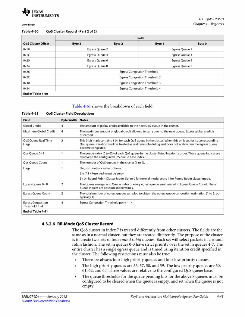
4.3 QMSS PDSPs
SPRUGR9D+++—January 2012 KeyStone Architecture Multicore Navigator User Guide 4-45Submit Documentation Feedback
Chapter 4—Registerswww.ti.com
Table 4-61 shows the breakdown of each field.
4.3.2.6 RR-Mode QoS Cluster RecordThe QoS cluster in index 7 is treated differently from other clusters. The fields are the same as in a normal cluster, but they are treated differently. The purpose of the cluster is to create two sets of four round robin queues. Each set will select packets in a round robin fashion. The set in queues 0-3 have strict priority over the set in queues 4-7. The entire cluster has a single egress queue and is timed using iteration credit specified in the cluster. The following restrictions must also be true:
• There are always four high priority queues and four low priority queues.• The high priority queues are 56, 57, 58, and 59. The low priority queues are 60,
61, 62, and 63. These values are relative to the configured QoS queue base.• The queue thresholds for the queue pending bits for the above 8 queues must be
configured to be cleared when the queue is empty, and set when the queue is not empty.
0x18 Egress Queue 2 Egress Queue 1
0x1C Egress Queue 4 Egress Queue 3
0x20 Egress Queue 6 Egress Queue 5
0x24 Egress Queue 8 Egress Queue 7
0x28 Egress Congestion Threshold 1
0x2C Egress Congestion Threshold 2
0x30 Egress Congestion Threshold 3
0x34 Egress Congestion Threshold 4
End of Table 4-60
Table 4-60 QoS Cluster Record (Part 2 of 2)
QoS Cluster Offset
Field
Byte 3 Byte 2 Byte 1 Byte 0
Table 4-61 QoS Cluster Field Descriptions
Field Byte Width Notes
Global Credit 4 The amount of global credit available to the next QoS queue in the cluster.
Maximum Global Credit 4 The maximum amount of global credit allowed to carry over to the next queue. Excess global credit is discarded.
QoS Queue Real Time Flags
2 This 9-bit mask contains 1 bit for each QoS queue in the cluster. When this bit is set for its corresponding QoS queue, iteration credit is treated as real time scheduling and does not scale when the egress queue become congested.
Qos Queue 0 - 8 1 The queue index (0 to 63) of each QoS queue in the cluster listed in priority order. These queue indices are relative to the configured QoS queue base index.
Qos Queue Count 1 The number of QoS queues in the cluster (1 to 9).
Flags 1 Flags to control cluster options.
Bits 7:1 - Reserved (must be zero)
Bit 0 - Round Robin Cluster Mode. Set to 0 for normal mode; set to 1 for Round Robin cluster mode.
Egress Queue 0 - 8 2 The Queue manger and Queue index of every egress queue enumerated in Egress Queue Count. These queue indices are absolute index values.
Egress Queue Count 2 The total number of egress queues sampled to obtain the egress queue congestion estimation (1 to 9, but typically 1).
Egress Congestion Threshold 1 - 4
4 Egress Congestion Threshold point 1 - 4.
End of Table 4-61

4.3 QMSS PDSPs
4-46 KeyStone Architecture Multicore Navigator User Guide SPRUGR9D+++—January 2012Submit Documentation Feedback
Chapter 4—Registers www.ti.com
The field usage for cluster record 7 is shown in Table 4-62.
Table 4-62 QoS Cluster Record 7
Original Name Actual Use Description
Global Credit na The amount of global credit available to the next QOS queue in the cluster
Maximum Global Credit
na The maximum amount of global credit allowed to carry over to the next queue. Excess global credit is discarded.
QoS Queue Real Time Flags
Packet Size Adjustment This field holds the value of a packet size adjustment that can be applied to each packet. For example, setting this value to 24 can adjust for the preamble, inter-packet gap, and CRC for packets without CRC being sent over Ethernet. This adjustment value is applied across all queues.
QoS Queue Count na The number of QOS queues in the cluster. It must be set to 8.
QoS Queue 0 … 3 High Priority Round Robin Queue Group
The queue index (0 to 63) of each QOS queue in the high priority round robin group. These queue indices are relative to the configured QOS queue base index. These fields must be set to 56, 57, 58, and 59 respectively.
QoS Queue 4 … 7 Low Priority Round Robin Queue Group
The queue index (0 to 63) of each QOS queue in the low priority round robin group. These queue indices are relative to the configured QOS queue base index. These fields must be set to 60, 61, 62, and 63 respectively.
QoS Queue 8 na This field is ignored.
Egress Queue Count na The total number of egress queues sampled to obtain the egress queue congestion estimation. It must be set to 1.
Egress Queue 0 na The Queue manger and Queue index of the egress queue used by the two round robin queue groups.
Egress Queue 1 ... 8 na These fields are ignored.
Egress Congestion Threshold 1
Iteration Credit This is the per timer tick real-time iteration credit for the cluster. (The iteration credit specified in each of the round robin queues is ignored.)
Egress Congestion Threshold 2
Max Egress Backlog This is the max number of bytes allowed to reside in the egress queue(s). Note that packets will be written until this threshold is crossed, so the actual number of bytes queued can be larger.
Egress Congestion Threshold 3
Queue Disable Mask This 8-bit mask contains 1 bit for each QOS queue in the cluster. When this bit is set for its corresponding QOS queue, the queue is disabled for forwarding.
Egress Congestion Threshold 4
na This field is ignored.
End of Table 4-62

4.3 QMSS PDSPs
SPRUGR9D+++—January 2012 KeyStone Architecture Multicore Navigator User Guide 4-47Submit Documentation Feedback
Chapter 4—Registerswww.ti.com
4.3.3 Navigator Runtime FirmwareThe Navigator runtime (NRT) firmware accomplishes static and dynamic load balancing of CorePacs. It does this by running a job scheduler in one or more PDSPs, and a job dispatcher in each CorePac where jobs are to be run. Jobs are pushed into QMSS queues, which are monitored by the NRT firmware, popped based on priority and other scheduler conditions, then recycled by the dispatcher tasks. Due to the complexity of NRT, a separate user guide is maintained for it. Please refer to it for programming information.
Currently, there are two builds for the navigator runtime: • NRT1 can be loaded on odd PDSPs and uses the hi priority (core specific)
interrupts• NRT2 can be loaded on even PDSPs and uses the lo priority (broadcast)
interrupts.
4.3.4 Interrupt OperationWhen a list buffer page is ready for processing, an interrupt is sent to the host CPU. The mapping between accumulator channel and host interrupt is fixed, however, each accumulator channel can be configured to any queue, or can be disabled, so there is a significant amount of flexibility in how queues can be mapped to host interrupts.
4.3.4.1 Interrupt HandshakingWhen a channel is first started, the PDSP owns both the ping and pong pages in host processor memory. When a page is filled by the PDSP, an interrupt is sent to the host. This tells the host that the PDSP wants it to take ownership of the page. This interrupt should be acknowledged by the host as quickly as possible to enable ownership of the page. After the interrupt is acknowledged, the host retains ownership of the page until a second interrupt firing and acknowledgement occurs.
• PDSP fills ping, and fires INT• Host CPU acknowledges INT, and takes ownership of ping• PDSP fills pong, and fires INT• Host CPU acknowledges INT, releasing ping, and takes ownership of pong• PDSP fills ping, and fires INT • Host CPU acknowledges INT, releasing pong, and takes ownership of ping

4.3 QMSS PDSPs
4-48 KeyStone Architecture Multicore Navigator User Guide SPRUGR9D+++—January 2012Submit Documentation Feedback
Chapter 4—Registers www.ti.com
Figure 4-36 illustrates the handshaking that occurs between the accumulator firmware, the INTD and the host software during processing of descriptor lists:
Figure 4-36 Handshaking During Processing of Descriptor Lists
4.3.4.2 Interrupt ProcessingWhen a host interrupt fires, the host processor can read a Status register in the INTD to see which accumulator channels have list buffer pages ready for processing (see register descriptions in the next section). However the host needs only to process the accumulator channels corresponding to the particular host interrupt that has fired.
As the host completes processing on a list buffer page, it informs the INTD by writing a 1 to the Int Count register corresponding to the accumulator channel processed. This tells the firmware that the opposite page is free to be used to store additional list entries.
Once the host has processed all list buffer pages for all the channels associate with the interrupt, it must then perform an EOI by writing the correct value to the INTD EOI register.
4.3.4.3 Interrupt GenerationEach accumulator channel will always trigger an interrupt when all the entries in the current buffer page are filled. It is also possible to trigger interrupts more quickly by configuring the interrupt pacing mode. The interrupt pacing mode allows for interrupts to be generated on a partially filled page, based on configurable packet activity and a configurable amount of elapsed time. Note that the pacing is per channel, and not per interrupt. So, if two channels are using the same host interrupt, then the host interrupt can be triggered as each channel independently requires.
AccumulatorFirmware wants to
trigger interrupt
AccumulatorFirmware reads INTDInt Count Reg(s) todetermine if clear
AccumulatorFirmware writes a bitin INTD Status Reg to
generate interrupt
INTD incrementscount in INTD Int
Count Reg(saturates at 3)
INTD generates Hostinterrupt if previous
interrupt was cleared
INTD decrementscount in INTD Int
Count Reg
INTD clears interruptinternally
When done, Hostwrites EOI value to
EOI register
Host writes a 1 toINTD Int Count Regafter each channel
Optionally, Host writesa bit to INTD Status
Clear Reg
Host processesdescriptor list(s)
Host receivesinterrupt and reads
Status Reg todetermine channels

4.3 QMSS PDSPs
SPRUGR9D+++—January 2012 KeyStone Architecture Multicore Navigator User Guide 4-49Submit Documentation Feedback
Chapter 4—Registerswww.ti.com
The available interrupt pacing modes are based on one of the following events:• Programmable delay since last interrupt to the host• Programmable delay since first packet on new activity• Programmable delay since last packet on new activity
The above event setting determines when the interrupt counter will be loaded and begin its countdown. An interrupt will trigger only when both the timing condition is met and there are packets available to forward to the host. If the timer expires with no packet activity, then the next incoming packet will trigger an immediate interrupt.
The time delay from the configured event is programmable, using the global timer value multiplied by. A timer setting of 0 seconds is useful in cases where the user wishes to trigger interrupts without delay based on any packet activity. Note that a delay of 0 seconds will always trigger an immediate interrupt on the first received packet no matter which of the three configurable pacing events are used.
4.3.4.4 Stall AvoidanceThe accumulator will hold off triggering a second interrupt to the host until any previous interrupt for that channel has been serviced. This will help avoid resource starvation.
4.3.5 QMSS PDSP RegistersThe PDSP control / status registers region contains registers for the PDSP. The control / status registers region is accessed using the Instruction RAM VBUSP slave interface and the PDSP_iram_regs_req input. The control / status registers region memory map is as follows:
Table 4-63 shows registers within each PDSP Register region.
Table 4-63 PDSP Region Registers
Offset Name Description
0x00000000 Control Register The Control Register allows software to setup and enable the PDSP.
0x00000004 Status Register The Status Register allows software to find (with a one-cycle delay) the PDSP’s Program Counter address.
0x0000000c Cycle Count Register The Cycle Count Register counts the number of cycles for which the PDSP has been enabled.
0x00000010 Stall Count Registers The Stall Count register counts the number of cycles for which the PDSP has been enabled, but unable to fetch a new instruction. It is linked to the Cycle Count Register such that this register reflects the stall cycles measured over the same cycles as counted by the cycle count register. Thus the value of this register is always less than or equal to cycle count.

4.3 QMSS PDSPs
4-50 KeyStone Architecture Multicore Navigator User Guide SPRUGR9D+++—January 2012Submit Documentation Feedback
Chapter 4—Registers www.ti.com
4.3.5.1 Control Register (0x00000000)The Control Register allows setup and control of the PDSP as shown in Figure 4-37.
Figure 4-37 Control Register (0x00000000)
31 16 15 14 13 9 8 7 4 3 2 1 0
PC_RESET STATE BIG Reserved STEP Reserved C_EN SLP P_EN S_RST
R/W-0 R-0 R-0 R-0 R/W-0 R--0 R/W-0 R/W-0 R/W-0 R-0
Legend: R = Read only; R/W = Read/Write; -n = value after reset
Table 4-64 Control Register Field Descriptions
Bits Field Description
31-16 PC_RESET Program Counter Reset Value: This field controls the address where the PDSP will start executing code from after it is taken out of reset.
15 STATE Run State: This bit indicates whether the PDSP is currently executing an instruction or is halted. 0 = PDSP is halted and host has access to the instruction RAM and debug registers regions.1 = PDSP is currently running and the host is locked out of the instruction RAM and debug registers regions
This bit is used by an external debug agent to know when the PDSP has actually halted when waiting for a HALT instruction to execute, a single step to finish, or any other time when the P_EN has been cleared.
14 BIG Big Endian state. Returns the mode that the PDSP is in.0 = Little Endian1 = Big Endian
13-9 Reserved Reads return 0 and writes have no effect
8 STEP Single Step Enable - This bit controls whether or not the PDSP will only execute a single instruction when enabled.0 = PDSP will free run when enabled1 = PDSP will execute a single instruction and then the pdsp_enable bit will be cleared.
Note that this bit does not actually enable the PDSP, it only sets the policy for how much code will be run after the PDSP is enabled. The P_EN bit must be explicitly asserted. It is expressly legal to initialize both the STEP and P_EN bits simultaneously. (2 independent writes are not required to cause the stated functionality)
7-4 Reserved Reads return 0 and writes have no effect
3 C_EN Cycle counter enable - Enables PDSP cycle counters0 = Counters not enabled1 = Counters enabled
2 SLP Processor sleep indicator - This bit indicates whether or not the PDSP is currently asleep.0 = PDSP is not asleep1 = PDSP is asleep
If this bit is written to a 0, the PDSP will be forced to power up from sleep mode.
1 P_EN Processor Enable - This bit controls whether or not the PDSP is allowed to fetch new instructions0 = PDSP is disabled1 = PDSP is enabled
If this bit is de-asserted while the PDSP is currently running and has completed the initial cycle of a multi-cycle instruction (LBxO,SBxO,SCAN, etc.), the current instruction will be allowed to complete before the PDSP pauses execution. Otherwise, the PDSP will halt immediately.
Because of the unpredictability/timing sensitivity of the instruction execution loop, this bit is not a reliable indication of whether or not the PDSP is currently running. The STATE bit should be consulted for an absolute indication of the run state of the core.
When the PDSP is halted, it's internal state remains coherent therefore this bit can be reasserted without issuing a software reset and the PDSP will resume processing exactly where it left off in the instruction stream.
0 S_RST Soft reset - when this bit is cleared, the PDSP will be reset. This bit is set back to 1 on the next cycle after it has been cleared.
End of Table 4-64

4.3 QMSS PDSPs
SPRUGR9D+++—January 2012 KeyStone Architecture Multicore Navigator User Guide 4-51Submit Documentation Feedback
Chapter 4—Registerswww.ti.com
4.3.5.2 Status Register (0x00000004)The Status Register (Figure 4-38) allows software to find (with a one-cycle delay) the PDSP’s Program Counter address.
4.3.5.3 Cycle Count Register (0x0000000C)The Cycle Count Register (Figure 4-39) counts the number of cycles for which the PDSP has been enabled.
Figure 4-38 Status Register (0x00000004)
31 16 15 0
Reserved PC_COUNTER
R-0 R-0
Legend: R = Read only; -n = value after reset
Table 4-65 Status Register Field Descriptions
Bit Field Description
30-16 Reserved Reads return 0 and writes have no effect
15-0 PC_COUNTER Program Counter: This field is a registered (one cycle delayed) reflection of the PDSP program counter. Note that the PC is an instruction address where each instruction is a 32 bit word. This is not a byte address and to compute the byte address just multiply the PC by 4 (PC of 2 = byte address of 0x8, or PC of 8 = byte address of 0x20).
End of Table 4-65
Figure 4-39 Cycle Count Register (0x0000000c)
31 0
COUNT
R/WC
Legend: R = Read only; W = Write only; -n = value after reset
Table 4-66 Cycle Count Register Field Descriptions
Bit Field Description
31-0 COUNT This value is incremented by 1 for every cycle during which the PDSP is enabled and the counter is enabled (both bits P_EN and C_EN set in the PDSP control register).
Counting halts while the PDSP is disabled or counter is disabled, and resumes when re-enabled.
Counter clears the counter enable bit in the PDSP control register when the count reaches 0xFFFFFFFF. (Count does does not wrap).
The register can be read at any time.
The register can be cleared when the counter or PDSP is disabled.
Clearing this register also clears the PDSP Stall Count Register.
End of Table 4-66
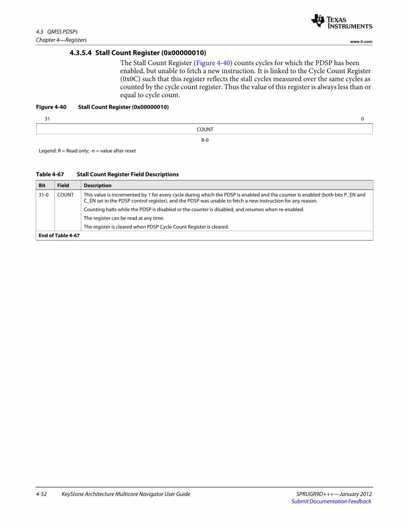
4.3 QMSS PDSPs
4-52 KeyStone Architecture Multicore Navigator User Guide SPRUGR9D+++—January 2012Submit Documentation Feedback
Chapter 4—Registers www.ti.com
4.3.5.4 Stall Count Register (0x00000010)The Stall Count Register (Figure 4-40) counts cycles for which the PDSP has been enabled, but unable to fetch a new instruction. It is linked to the Cycle Count Register (0x0C) such that this register reflects the stall cycles measured over the same cycles as counted by the cycle count register. Thus the value of this register is always less than or equal to cycle count.
Figure 4-40 Stall Count Register (0x00000010)
31 0
COUNT
R-0
Legend: R = Read only; -n = value after reset
Table 4-67 Stall Count Register Field Descriptions
Bit Field Description
31-0 COUNT This value is incremented by 1 for every cycle during which the PDSP is enabled and the counter is enabled (both bits P_EN and C_EN set in the PDSP control register), and the PDSP was unable to fetch a new instruction for any reason.
Counting halts while the PDSP is disabled or the counter is disabled, and resumes when re-enabled.
The register can be read at any time.
The register is cleared when PDSP Cycle Count Register is cleared.
End of Table 4-67

4.4 QMSS Interrupt Distributor
SPRUGR9D+++—January 2012 KeyStone Architecture Multicore Navigator User Guide 4-53Submit Documentation Feedback
Chapter 4—Registerswww.ti.com
4.4 QMSS Interrupt DistributorThe queue manager sub system contains an interrupt distributor to route QMSS interrupts to the CorePacs. The QMSS’ INTD is a subset of the full INTD specification, and only those registers that are mapped and have functionality in QMSS are described in the following sections.
4.4.1 INTD Register RegionTable 4-68 shows registers within the INTD config region.
Table 4-68 INTD Region Registers
Offset Name Description
0x00000000 Revision Register The Revision Register contains the major and minor revisions for the INTD module.
0x00000010 End of Interrupt Register The EOI Register allows software to clear specific interrupts within the INTD module. Unless interrupts have been cleared, they will not trigger again. Each interrupt within QMSS is cleared by writing a specific 8-bit value to the register. Writing to this register does not clear corresponding bits in the Status Registers, nor does it clear interrupts within the CorePac’s interrupt controller. When the EOI is written, the interrupt will trigger again if the corresponding Int Count Register is not zero, (this should not happen with firmware generated interrupts).
0x00000200, 204, 210
Status Registers 0, 1, and 4 An array of five registers that provide status on the interrupts managed by the INTD. Registers 2 and 3 are not used in the QMSS INTD. Registers 0, 1, and 4 expose one bit per QMSS interrupt (see each individual register layout). Reading the registers returns a 1 bit for each interrupt that has been triggered. Writing to the registers causes an interrupt to be triggered for each set (1) bit just as if the corresponding input interrupt had arrived.
0x00000280, 284, 290
Status Clear Registers 0, 1, and 4 An array of five registers that provide status on the interrupts managed by the INTD. Registers 2 and 3 are not used in the QMSS INTD. Registers 0, 1, and 4 expose one bit per QMSS interrupt (see each individual register layout). Reading the registers returns a 1 bit for each interrupt that has been triggered. Writing to the registers causes status bits to be cleared. Clearing status bits does not affect the count of interrupts in the Int Count Registers, nor does it clear the interrupt internally (the EOI register still needs to be written). In blocks where a single event can represent multiple grouped interrupts, these registers can be used to determine which interrupts have triggered. Because QMSS does not group interrupts, this is needed only to keep it clear which events have been processed.
0x00000300 to 3C4 Interrupt N Count Registers An array of fifty registers, one per QMSS interrupt. Each register contains a count of the interrupts that have triggered and not processed. In QMSS, this count saturates at 3. Reading the register returns the count. Writing a non-zero value to the register subtracts that value from the count. Writing a 0 clears the count.
End of Table 4-68

4.4 QMSS Interrupt Distributor
4-54 KeyStone Architecture Multicore Navigator User Guide SPRUGR9D+++—January 2012Submit Documentation Feedback
Chapter 4—Registers www.ti.com
4.4.1.1 Revision Register (0x00000000)The Revision Register contains the major and minor revisions for the module as shown in Figure 4-41.
4.4.1.2 End Of Interrupt (EOI) Register (0x00000010)The EOI Register (Figure 4-42) allows software to clear specific interrupts within the INTD module. Unless interrupts have been cleared, they will not trigger again. Each interrupt within the QMSS is cleared by writing a specific 8-bit value to the register. Writing to this register does not clear corresponding bits in the Status Registers, nor does it clear interrupts within the CorePac’s interrupt controller. When the EOI is written, the interrupt will trigger again if the corresponding Int Count Register is not 0, (this should not happen with firmware generated interrupts).
Figure 4-41 Revision Register (0x00000000)
31 30 29 28 27 16 15 11 10 8 7 6 5 0
SCHEME Reserved MODULE REVRTL REVMAJ REVCUSTOM REVMIN
R-1 R-0 R-0xe83 R-16 R-1 R-0 R-0
Legend: R = Read only; W = Write only; -n = value after reset
Table 4-69 Revision Register Field Descriptions
Bits Field Description
31-30 SCHEME Scheme that this register is compliant with
29-28 Reserved Reads return 0 and writes have no effect
27-16 MODULE Function
15-11 REVRTL RTL revision
10-8 REVMAJ Major revision
7-6 REVCUSTOM Custom revision
5-0 REVMIN Minor revision
End of Table 4-69
Figure 4-42 EOI Register (0x00000010)
31 8 7 0
Reserved INT_VAL
R-0 R-W
Legend: R = Read only; R/W = Read/Write; -n = value after reset
Table 4-70 EOI Register Field Descriptions
Bit Field Description
30-8 Reserved Reads return 0 and writes have no effect
7-0 INT_VAL Valid values are: (other values are ignored)0, 1 = PKTDMA Rx starvation interrupts 0 and 1 (respectively)2 - 33 = High-priority channel interrupts 0 through 31 (respectively)34 - 49 = Low-priority channel interrupts 0 through 15 (respectively)
End of Table 4-70
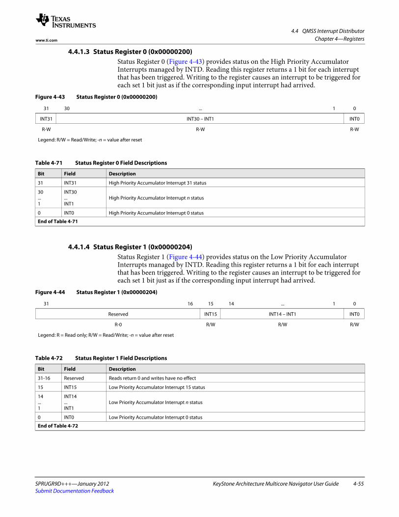
4.4 QMSS Interrupt Distributor
SPRUGR9D+++—January 2012 KeyStone Architecture Multicore Navigator User Guide 4-55Submit Documentation Feedback
Chapter 4—Registerswww.ti.com
4.4.1.3 Status Register 0 (0x00000200)Status Register 0 (Figure 4-43) provides status on the High Priority Accumulator Interrupts managed by INTD. Reading this register returns a 1 bit for each interrupt that has been triggered. Writing to the register causes an interrupt to be triggered for each set 1 bit just as if the corresponding input interrupt had arrived.
4.4.1.4 Status Register 1 (0x00000204)Status Register 1 (Figure 4-44) provides status on the Low Priority Accumulator Interrupts managed by INTD. Reading this register returns a 1 bit for each interrupt that has been triggered. Writing to the register causes an interrupt to be triggered for each set 1 bit just as if the corresponding input interrupt had arrived.
Figure 4-43 Status Register 0 (0x00000200)
31 30 ... 1 0
INT31 INT30 – INT1 INT0
R-W R-W R-W
Legend: R/W = Read/Write; -n = value after reset
Table 4-71 Status Register 0 Field Descriptions
Bit Field Description
31 INT31 High Priority Accumulator Interrupt 31 status
30...1
INT30...INT1
High Priority Accumulator Interrupt n status
0 INT0 High Priority Accumulator Interrupt 0 status
End of Table 4-71
Figure 4-44 Status Register 1 (0x00000204)
31 16 15 14 ... 1 0
Reserved INT15 INT14 – INT1 INT0
R-0 R/W R/W R/W
Legend: R = Read only; R/W = Read/Write; -n = value after reset
Table 4-72 Status Register 1 Field Descriptions
Bit Field Description
31-16 Reserved Reads return 0 and writes have no effect
15 INT15 Low Priority Accumulator Interrupt 15 status
14...1
INT14 ...INT1
Low Priority Accumulator Interrupt n status
0 INT0 Low Priority Accumulator Interrupt 0 status
End of Table 4-72

4.4 QMSS Interrupt Distributor
4-56 KeyStone Architecture Multicore Navigator User Guide SPRUGR9D+++—January 2012Submit Documentation Feedback
Chapter 4—Registers www.ti.com
4.4.1.5 Status Register 4 (0x00000210)Status Register 4 (Figure 4-45) provides status on the QMSS PKTDMA Starvation Interrupts managed by the INTD. Reading this register returns a 1 bit for each interrupt that has been triggered. Writing to the register causes an interrupt to be triggered for each set 1 bit just as if the corresponding input interrupt had arrived.
4.4.1.6 Status Clear Register 0 (0x00000280)Status Register 0 (Figure 4-46) provides status on the high-priority accumulator interrupts managed by the INTD. Reading this register returns a 1 bit for each interrupt that has been triggered. Writing to the register causes status bits to be cleared. Clearing status bits does not affect the count of interrupts in the Int Count Registers, nor does it clear the interrupt internally (the EOI register still needs to be written). In blocks where a single event can represent multiple grouped interrupts, these registers can be used to determine which interrupts have triggered. Because the QMSS does not group interrupts, this is needed only to keep clear which events have been processed (it is optional).
Figure 4-45 Status Register 4 (0x00000210)
31 2 1 0
Reserved INT1 INT0
R-0 R/W R/W
Legend: R = Read only; R/W = Read/Write; -n = value after reset
Table 4-73 Status Register 4 Field Descriptions
Bit Field Description
31-2 Reserved Reads return 0 and writes have no effect
1 INT1 PKTDMA starvation interrupt 1 status. This is the status of Rx MOP starvation (available only for host type packets).
0 INT0 PKTDMA starvation interrupt 0 status. This is the status of Rx SOP starvation.
End of Table 4-73
Figure 4-46 Status Clear Register 0 (0x00000280)
31 30 ... 1 0
INT31 INT30 ... INT1 INT0
R/W R/W R/W
Legend: R/W = Read/Write; -n = value after reset
Table 4-74 Status Clear Register 0 Field Descriptions
Bit Field Description
31 INT31 High Priority Accumulator Interrupt 31 status
30...1
INT30...INT1
High Priority Accumulator Interrupt n status
0 INT0 High Priority Accumulator Interrupt 0 status
End of Table 4-74

4.4 QMSS Interrupt Distributor
SPRUGR9D+++—January 2012 KeyStone Architecture Multicore Navigator User Guide 4-57Submit Documentation Feedback
Chapter 4—Registerswww.ti.com
4.4.1.7 Status Clear Register 1 (0x00000284)Status Register 1 (Figure 4-47) provides status on the low-priority accumulator interrupts managed by the INTD. Reading this register returns a 1 bit for each interrupt that has been triggered. Writing to the register causes status bits to be cleared. Clearing status bits does not affect the count of interrupts in the Int Count Registers, nor does it clear the interrupt internally (the EOI register still needs to be written). In blocks where a single event can represent multiple grouped interrupts, these registers can be used to determine which interrupts have triggered. Because the QMSS does not group interrupts, this is needed only to keep clear which events have been processed (it is optional).
Figure 4-47 Status Clear Register 1 (0x00000284)
31 16 15 14 ... 1 0
Reserved INT15 INT14 ... INT1 INT0
R-0 R/W R/W R/W
Legend: R = Read only; R/W = Read/Write; -n = value after reset
Table 4-75 Status Clear Register 1 Field Descriptions
Bit Field Description
31-16 Reserved Reads return 0 and writes have no effect
15 INT15 Low Priority Accumulator Interrupt 15 status
14...1
INT14...INT1
Low Priority Accumulator Interrupt n status
0 INT0 Low Priority Accumulator Interrupt 0 status
End of Table 4-75

4.4 QMSS Interrupt Distributor
4-58 KeyStone Architecture Multicore Navigator User Guide SPRUGR9D+++—January 2012Submit Documentation Feedback
Chapter 4—Registers www.ti.com
4.4.1.8 Status Clear Register 4 (0x00000290)Status Register 4 (Figure 4-48) provides status on the QMSS PKTDMA starvation interrupts managed by the INTD. Reading this register returns a 1 bit for each interrupt that has been triggered. Writing to the register causes status bits to be cleared. Clearing status bits does not affect the count of interrupts in the Int Count Registers, nor does it clear the interrupt internally (the EOI register still needs to be written). In blocks where a single event can represent multiple grouped interrupts, these registers can be used to determine which interrupts have triggered. Because the QMSS does not group interrupts, this is needed only to keep clear which events have been processed (it is optional).
Figure 4-48 Status Clear Register 4 (0x00000290)
31 2 1 0
Reserved INT1 INT0
R-0 R/W R/W
Legend: R = Read only; R/W = Read/Write; -n = value after reset
Table 4-76 Status Clear Register 4 Field Descriptions
Bit Field Description
31-2 Reserved Reads return 0 and writes have no effect
1 INT1 PKTDMA Starvation Interrupt 1 status. This clears the status of Rx MOP starvation (available only for host-type packets).
0 INT0 PKTDMA Starvation Interrupt 0 status. This clears the status of Rx SOP starvation.
End of Table 4-76
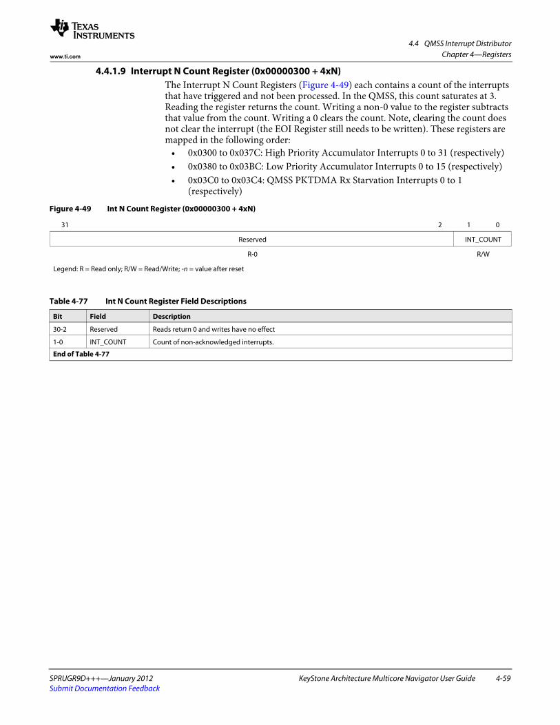
4.4 QMSS Interrupt Distributor
SPRUGR9D+++—January 2012 KeyStone Architecture Multicore Navigator User Guide 4-59Submit Documentation Feedback
Chapter 4—Registerswww.ti.com
4.4.1.9 Interrupt N Count Register (0x00000300 + 4xN)The Interrupt N Count Registers (Figure 4-49) each contains a count of the interrupts that have triggered and not been processed. In the QMSS, this count saturates at 3. Reading the register returns the count. Writing a non-0 value to the register subtracts that value from the count. Writing a 0 clears the count. Note, clearing the count does not clear the interrupt (the EOI Register still needs to be written). These registers are mapped in the following order:
• 0x0300 to 0x037C: High Priority Accumulator Interrupts 0 to 31 (respectively)• 0x0380 to 0x03BC: Low Priority Accumulator Interrupts 0 to 15 (respectively)• 0x03C0 to 0x03C4: QMSS PKTDMA Rx Starvation Interrupts 0 to 1
(respectively)
Figure 4-49 Int N Count Register (0x00000300 + 4xN)
31 2 1 0
Reserved INT_COUNT
R-0 R/W
Legend: R = Read only; R/W = Read/Write; -n = value after reset
Table 4-77 Int N Count Register Field Descriptions
Bit Field Description
30-2 Reserved Reads return 0 and writes have no effect
1-0 INT_COUNT Count of non-acknowledged interrupts.
End of Table 4-77

4.4 QMSS Interrupt Distributor
4-60 KeyStone Architecture Multicore Navigator User Guide SPRUGR9D+++—January 2012Submit Documentation Feedback
Chapter 4—Registers www.ti.com

SPRUGR9D+++—January 2012 KeyStone Architecture Multicore Navigator User Guide 5-1Submit Documentation Feedback
Chapter 5
Mapping Information
This chapter covers the mapping of Multicore Navigator resources in the device. The resources described here include the mapping of queues, packet DMA (PKTDMA) channels, accumulator interrupts, and memory (memory mapped register region offsets).
5.1 "Queue Maps" on page 5-2 5.2 "Interrupt Maps" on page 5-4 5.3 "Memory Maps" on page 5-10 5.4 "Packet DMA Channel Map" on page 5-11

5.1 Queue Maps
5-2 KeyStone Architecture Multicore Navigator User Guide SPRUGR9D+++—January 2012Submit Documentation Feedback
Chapter 5—Mapping Information www.ti.com
5.1 Queue MapsThe queue manager supports a total of 8192 queues (16K for KeyStone 2). Most of them are available for general purpose use, but some are dedicated for special use, and in some cases, have special hardware functionality associated with them. Table 5-1 shows the mapping of queues for TCI6616. The following tables show differences from TCI6616. Queues not listed are general purpose queues.
Note—Any queue that is not used by the application for hardware purposes may be used as a general purpose queue. You must only insure that the corresponding hardware functionality is not enabled. For example, if Low Priority accumulation is not used, queues 0 to 511 may be used as general purpose queues.
Table 5-1 Queue Map for TCI6616
Queue Range Number of Queues Purpose
0 to 511 512 Normally used by low priority accumulation. The low priority accumulator uses up to 512 queues divided into 16 channels, each channel being 32 continuous queues. Each channel triggers one broadcast interrupt. These queues can also be used as general purpose queues.
512 to 639 128 AIF Tx queues. Each queue has a dedicated queue pending signal that drives a Tx DMA channel.
640 to 648 9 PA Tx queues. Each queue has a dedicated queue pending signal that drives a Tx DMA channel.
662 to 671 10 INTC0/INTC1 queue pend queues. These queues have dedicated queue pending signals wired directly into the chip level INTC0 and/or INTC1. Note that the event mapping can differ for each device.
672 to 687 16 SRIO Tx queues. Each queue has a dedicated queue pending signal that drives a Tx DMA channel.
688 to 695 8 FFTC_A, B Tx queues. Each queue has a dedicated queue pending signal that drives a Tx DMA channel.
704 to 735 32 Normally used by high priority accumulation. The high priority accumulator uses up to 32 queues, one per channel. Each channel triggers a core-specific interrupt. These queues can also be used as general purpose queues.
736 to 799 64 Queues with starvation counters readable by the host. Starvation counters increment each time a pop is performed on an empty queue, and reset when the queue is not empty (or when the starvation count is read).
800 to 831 32 QMSS Tx queues. Used for infrastructure (core to core) DMA copies and notification.
832 to 863 32 General purpose queues, or may be configured for use by QoS traffic shaping firmware.
864 to 895 32 HyperLink queue pend queues. These queues have dedicated queue pending signals wired directly into HyperLink.
896 to 8191 7296 General purpose. Due to the mapping of logical to physical queues in the PKTDMA interfaces, the use of 0xFFF in PKTDMA qnum fields is reserved to specify non-override conditions.
End of Table 5-1
Table 5-2 Queue Map Delta for TCI660x/C667x
Queue Range Number of Queues Purpose
652 to 671 20 INTC0/INTC1 queue pend queues. These queues have dedicated queue pending signals wired directly into the chip level INTC0 and/or INTC1. Note that the event mapping can differ for each device.
End of Table 5-2

5.1 Queue Maps
SPRUGR9D+++—January 2012 KeyStone Architecture Multicore Navigator User Guide 5-3Submit Documentation Feedback
Chapter 5—Mapping Informationwww.ti.com
Table 5-3 Queue Map Delta for TCI6618/C6670
Queue Range Number of Queues Purpose
864 to 867 4 FFTC_C Tx queues. Each queue has a dedicated queue pending signal that drives a Tx DMA channel. Also routed to HyperLink.
868 to 875 8 BCP Tx queues. Each queue has a dedicated queue pending signal that drives a Tx DMA channel. Also routed to HyperLink.
864 to 895 32 HyperLink queue pend queues. Note that the first 12 overlap with FFTC_C and BCP. If used for FFTC_C and BCP, these queues should not be used for HyperLink.
End of Table 5-3
Table 5-4 Queue Map Delta for TCI6614
Queue Range Number of Queues Purpose
650 to 657 8 ARM queue pend queues. These queues have dedicated queue pending signals wired directly to the ARM.
670 to 671 2 ARM queue pend queues. These queues have dedicated queue pending signals wired directly to the ARM. Note that these are also routed to INTC0.
864 to 871 8 BCP Tx queues. Each queue has a dedicated queue pending signal that drives a Tx DMA channel. Note that these are also routed to HyperLink.
End of Table 5-4
Table 5-5 Queue Map Delta for TCI6634
Queue Range Number of Queues Purpose
652 to 671 20 INTC0/C1/C2 queue pend queues. These queues have dedicated queue pending signals wired directly into the chip level interrupt controllers.
864 to 871 8 BCP Tx queues. Each queue has a dedicated queue pending signal that drives a Tx DMA channel.
872 to 887 16 FFTC_C , _D, _E and _F Tx queues (four per FFTC). Each queue has a dedicated queue pending signal that drives a Tx DMA channel.
1023 1 Dedicated queue used by Navigator Runtime (PDSP firmware). Can be used as general purpose if NRT is not used. Other queues used by NRT are configurable at initialization.
8192 to 8703 512 Normally used by low priority accumulation for QM2. The low priority accumulator uses up to 512 queues divided into 16 channels, each channel being 32 continuous queues. Each channel triggers one broadcast interrupt. These queues can also be used as general purpose queues.
8704 to 8735 32 ARM Interrupt controller queue pend queues.
8736 to 8743 32 EDMA4 queue pend queues.
8744 to 8751 8 HyperLink broadcast queue pend queues.
8752 to 8759 8 XGE queue pend queues.
8796 to 8811 16 HyperLink 0 queue pend queues.
8812 to 8843 32 DXB queue pend queues.
8844 to 8863 20 INTC0/C1/C2 queue pend queues. These queues have dedicated queue pending signals wired directly into the chip level interrupt controllers.
8864 to 8879 16 HyperLink 1 queue pend queues.
8896 to 8927 32 Normally used by high priority accumulation for QM2. The high priority accumulator uses up to 32 queues, one per channel. Each channel triggers a core-specific interrupt. These queues can also be used as general purpose queues.
8928 to 8991 64 Queues with starvation counters readable by the host. Starvation counters increment each time a pop is performed on an empty queue, and reset when the queue is not empty (or when the starvation count is read).
8992 to 9023 32 QMSS Tx queues for pktDMA2. Used for infrastructure (core to core) DMA copies and notification.
9024 to 16383 7360 General purpose queues.
End of Table 5-5

5.2 Interrupt Maps
5-4 KeyStone Architecture Multicore Navigator User Guide SPRUGR9D+++—January 2012Submit Documentation Feedback
Chapter 5—Mapping Information www.ti.com
5.2 Interrupt Maps5.2.1 KeyStone 1 TCI661x, C6670 devices
Table 5-6 shows the mapping of queues to high priority accumulation channels to DSP and function for TCI661x (16, 18, 14) and C6670 devices. Note that each queue and event maps to a specific DSP core. Also, the queues shown are the suggested mapping. Other queues may be used. The channel to event mapping is fixed.
Table 5-7 shows the mapping of queues to low priority accumulation channels. All low priority interrupts map to all DSPs. Also, the queues shown are the suggested mapping. Other queues may be used. The channel to event mapping is fixed.
Table 5-8 shows the mapping of queues with queue pend signals tied to the chip-level CP-INTC0 interrupt controller. The mapping of queue number to CP-INTC input is fixed and cannot be changed.
Table 5-6 High Priority Queue Mapping (TCI661x and C6670)
DSP Queue High Priority Channel Interrupt Name DSP Event
core N
(N = 0 to 3)
704 + N N qmss_intr1_0+N 48
708 + N N + 4 qmss_intr1_4+N 49
712 + N N + 8 qmss_intr1_8+N 50
716 + N N + 12 qmss_intr1_12+N 51
720 + N N + 16 qmss_intr1_16+N 52
724 + N N + 20 qmss_intr1_20+N 53
728 + N N + 24 qmss_intr1_24+N 54
732 + N N + 28 qmss_intr1_28+N 55
End of Table 5-6
Table 5-7 Low Priority Queue Mapping
Queues Low Priority Channel Interrupt Name DSP Event
0 to 31 0 qmss_intr0_0 32
32 to 63 1 qmss_intr0_1 33
64 to 95 2 qmss_intr0_2 34
. . . . . . . . . . . .
448 to 479 14 qmss_intr0_14 46
480 to 511 15 qmss_intr0_15 47
End of Table 5-7
Table 5-8 CPINTC Queue Mapping (TCI661x and C6670) (Part 1 of 2)
Queue Interrupt Name CPINTC0 Input Event
662 qm_int_pass_txq_pend_22 134
663 qm_int_pass_txq_pend_23 135
664 qm_int_pass_txq_pend_24 136
665 qm_int_pass_txq_pend_25 137
666 qm_int_pass_txq_pend_26 138
667 qm_int_pass_txq_pend_27 139
668 qm_int_pass_txq_pend_28 140
669 qm_int_pass_txq_pend_29 141

5.2 Interrupt Maps
SPRUGR9D+++—January 2012 KeyStone Architecture Multicore Navigator User Guide 5-5Submit Documentation Feedback
Chapter 5—Mapping Informationwww.ti.com
For example, to map queue 665 to trigger TCI6616 DSP event 57:• Map CP-INTC input 137 to CP-INTC (output) channel 1.• Enable system interrupt 137.• Enable DSP event 57.• (Repeat on each core you desire to handle the event.)
670 qm_int_pass_txq_pend_30 142
671 qm_int_pass_txq_pend_31 175
End of Table 5-8
Table 5-8 CPINTC Queue Mapping (TCI661x and C6670) (Part 2 of 2)
Queue Interrupt Name CPINTC0 Input Event
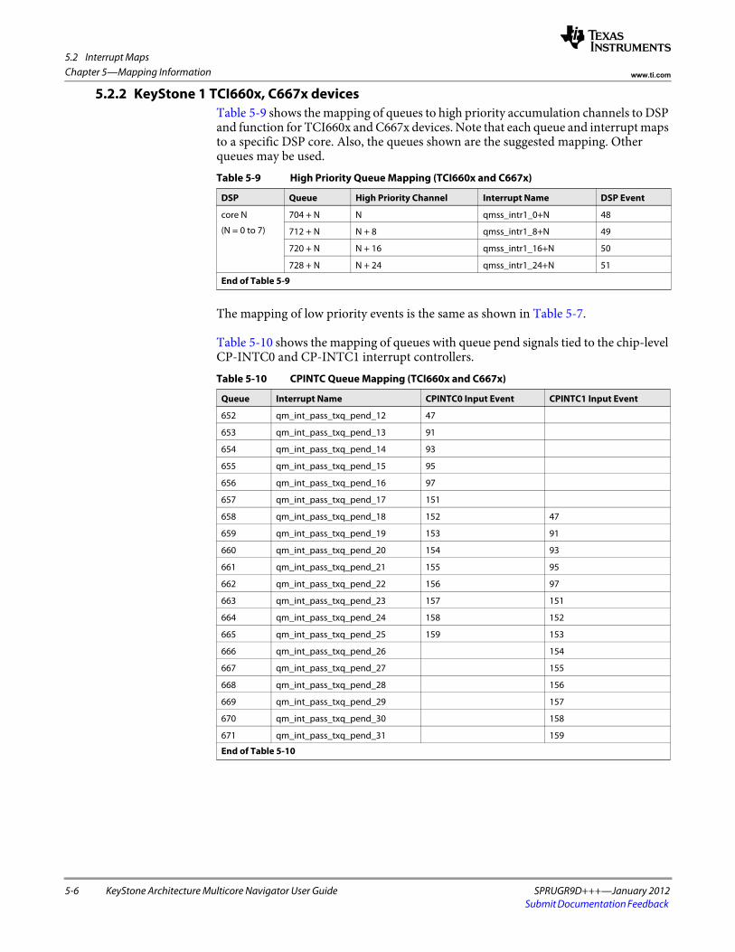
5.2 Interrupt Maps
5-6 KeyStone Architecture Multicore Navigator User Guide SPRUGR9D+++—January 2012Submit Documentation Feedback
Chapter 5—Mapping Information www.ti.com
5.2.2 KeyStone 1 TCI660x, C667x devicesTable 5-9 shows the mapping of queues to high priority accumulation channels to DSP and function for TCI660x and C667x devices. Note that each queue and interrupt maps to a specific DSP core. Also, the queues shown are the suggested mapping. Other queues may be used.
The mapping of low priority events is the same as shown in Table 5-7.
Table 5-10 shows the mapping of queues with queue pend signals tied to the chip-level CP-INTC0 and CP-INTC1 interrupt controllers.
Table 5-9 High Priority Queue Mapping (TCI660x and C667x)
DSP Queue High Priority Channel Interrupt Name DSP Event
core N
(N = 0 to 7)
704 + N N qmss_intr1_0+N 48
712 + N N + 8 qmss_intr1_8+N 49
720 + N N + 16 qmss_intr1_16+N 50
728 + N N + 24 qmss_intr1_24+N 51
End of Table 5-9
Table 5-10 CPINTC Queue Mapping (TCI660x and C667x)
Queue Interrupt Name CPINTC0 Input Event CPINTC1 Input Event
652 qm_int_pass_txq_pend_12 47
653 qm_int_pass_txq_pend_13 91
654 qm_int_pass_txq_pend_14 93
655 qm_int_pass_txq_pend_15 95
656 qm_int_pass_txq_pend_16 97
657 qm_int_pass_txq_pend_17 151
658 qm_int_pass_txq_pend_18 152 47
659 qm_int_pass_txq_pend_19 153 91
660 qm_int_pass_txq_pend_20 154 93
661 qm_int_pass_txq_pend_21 155 95
662 qm_int_pass_txq_pend_22 156 97
663 qm_int_pass_txq_pend_23 157 151
664 qm_int_pass_txq_pend_24 158 152
665 qm_int_pass_txq_pend_25 159 153
666 qm_int_pass_txq_pend_26 154
667 qm_int_pass_txq_pend_27 155
668 qm_int_pass_txq_pend_28 156
669 qm_int_pass_txq_pend_29 157
670 qm_int_pass_txq_pend_30 158
671 qm_int_pass_txq_pend_31 159
End of Table 5-10

5.2 Interrupt Maps
SPRUGR9D+++—January 2012 KeyStone Architecture Multicore Navigator User Guide 5-7Submit Documentation Feedback
Chapter 5—Mapping Informationwww.ti.com
5.2.3 KeyStone 2 devicesTable 5-11 and Table 5-13 show the mapping of queues to high priority accumulation channels (INTD interrupts) for TCI6634 and C6608T. Note that each queue and interrupt maps to a specific DSP core, but the queues shown are the suggested mapping. Other queues may be used. These interrupts also map to CPINTCx inputs (not shown).
The mapping of low priority events (INTD interrupts) is shown in Table 5-13 and Table 5-14. Other queues may be used. The channel to event mapping is fixed.
Table 5-11 High Priority Queue Mapping (TCI6634)
DSP Queue High Priority Channel Interrupt Name DSP Event
core N
(N = 0 to 7)
704 + N N qmss1_intr1_0+N 48
712 + N N + 8 qmss1_intr1_8+N 49
720 + N N + 16 qmss1_intr1_16+N 50
728 + N N + 24 qmss1_intr1_24+N 51
8896 + N N qmss2_intr1_0+N 52
8904 + N N + 8 qmss2_intr1_8+N 53
8912 + N N + 16 qmss2_intr1_16+N 54
8920 + N N + 24 qmss2_intr1_24+N 55
End of Table 5-11
Table 5-12 High Priority Queue Mapping (C6608T)
DSP Queue High Priority Channel Interrupt Name DSP Event
core N
(N = 0 to 7)
704 + N N qmss1_intr1_0+N 48
712 + N N + 8 qmss1_intr1_8+N 49
720 + N N + 16 qmss1_intr1_16+N 50
728 + N N + 24 qmss1_intr1_24+N 51
8896 + N N qmss2_intr1_0+N na
8904 + N N + 8 qmss2_intr1_8+N na
8912 + N N + 16 qmss2_intr1_16+N na
8920 + N N + 24 qmss2_intr1_24+N na
End of Table 5-12
Table 5-13 Low Priority Queue Mapping (TCI6634)
Queues Low Priority Channel Interrupt Name CPINTC0 CPINTC1
0 to 31 0 qmss1_intr0_0 320 320
32 to 63 1 qmss1_intr0_1 321 321
. . . . . . . . .
480 to 511 15 qmss1_intr0_15 335 335
8192 to 8223 0 qmss2_intr0_0 336 336
8224 to 8255 1 qmss2_intr0_1 337 337
. . . . . . . . .
8672 to 8703 15 qmss2_intr0_15 351 351
End of Table 5-13

5.2 Interrupt Maps
5-8 KeyStone Architecture Multicore Navigator User Guide SPRUGR9D+++—January 2012Submit Documentation Feedback
Chapter 5—Mapping Information www.ti.com
Table 5-15 shows the mapping of queues with queue pend signals tied to the chip-level CP-INTC interrupt controllers.
Table 5-14 Low Priority Queue Mapping (TCI6608T)
Queues Low Priority Channel Interrupt Name DSP Event
0 to 31 0 qmss1_intr0_0 32
32 to 63 1 qmss1_intr0_1 33
. . . . . . . . . . . .
480 to 511 15 qmss1_intr0_15 47
8192 to 8223 0 qmss2_intr0_0 na
8224 to 8255 1 qmss2_intr0_1 na
. . . . . . . . . na
8672 to 8703 15 qmss2_intr0_15 na
End of Table 5-14
Table 5-15 CPINTC Queue Mapping (TCI6634) (Part 1 of 2)
Queue Interrupt NameCPINTC0 Input Event
CPINTC1 Input Event
CPINTC2 Input Event
652 qm_int_pass_txq_pend_12 47 292 237
653 qm_int_pass_txq_pend_13 91 293 238
654 qm_int_pass_txq_pend_14 93 294 239
655 qm_int_pass_txq_pend_15 95 295 240
656 qm_int_pass_txq_pend_16 97 296 241
657 qm_int_pass_txq_pend_17 151 297 242
658 qm_int_pass_txq_pend_18 152 47 243
659 qm_int_pass_txq_pend_19 153 91 244
660 qm_int_pass_txq_pend_20 154 93 245
661 qm_int_pass_txq_pend_21 155 95 246
662 qm_int_pass_txq_pend_22 156 97 247
663 qm_int_pass_txq_pend_23 157 151 248
664 qm_int_pass_txq_pend_24 158 152 249
665 qm_int_pass_txq_pend_25 159 153 250
666 qm_int_pass_txq_pend_26 292 154 251
667 qm_int_pass_txq_pend_27 293 155 252
668 qm_int_pass_txq_pend_28 294 156 253
669 qm_int_pass_txq_pend_29 295 157 254
670 qm_int_pass_txq_pend_30 296 158 255
671 qm_int_pass_txq_pend_31 297 159 256
8844 qm_other_txq_pend_140 298 298 257
8845 qm_other_txq_pend_141 299 299 258
8846 qm_other_txq_pend_142 300 300 259
8847 qm_other_txq_pend_143 301 301 260
8848 qm_other_txq_pend_144 302 302 261
8849 qm_other_txq_pend_145 303 303 262
8850 qm_other_txq_pend_146 304 304 263
8851 qm_other_txq_pend_147 305 305 264
8852 qm_other_txq_pend_148 306 306 265

5.2 Interrupt Maps
SPRUGR9D+++—January 2012 KeyStone Architecture Multicore Navigator User Guide 5-9Submit Documentation Feedback
Chapter 5—Mapping Informationwww.ti.com
8853 qm_other_txq_pend_149 307 307 266
8854 qm_other_txq_pend_150 308 308 267
8855 qm_other_txq_pend_151 309 309 268
8856 qm_other_txq_pend_152 310 310 269
8857 qm_other_txq_pend_153 311 311 270
8858 qm_other_txq_pend_154 312 312 271
8859 qm_other_txq_pend_155 313 313 272
8860 qm_other_txq_pend_156 314 314 273
8861 qm_other_txq_pend_157 315 315 274
8862 qm_other_txq_pend_158 316 316 275
8863 qm_other_txq_pend_159 317 317 276
End of Table 5-15
Table 5-15 CPINTC Queue Mapping (TCI6634) (Part 2 of 2)
Queue Interrupt NameCPINTC0 Input Event
CPINTC1 Input Event
CPINTC2 Input Event

5.3 Memory Maps
5-10 KeyStone Architecture Multicore Navigator User Guide SPRUGR9D+++—January 2012Submit Documentation Feedback
Chapter 5—Mapping Information www.ti.com
5.3 Memory MapsThe following maps show the base offsets for all Multicore Navigator register regions.
5.3.1 QMSS Register Memory MapThe queue manager module contains several memory regions where programmable registers are found. Table 5-16 lists these region offsets. For regions with multiple instances (such as the PDSP regions), the offset to the next region is given.
Note—For KeyStone 2, some memory regions are placed in contiguous memory to allow consistent addressing schemes to access QM1 and QM2 as a single, large Queue Manager. These regions are marked with * in Table 5-16.
5.3.2 KeyStone 1 PKTDMA Register Memory MapThe PKTDMA register region offsets vary from peripheral to peripheral. In some cases, the offsets are determined by the number of channels supported by the particular PKTDMA. The addresses shown include the peripheral’s base address.
Table 5-16 QMSS Register Memory Map
KeyStone 1 KeyStone 2
Queue Manager Region Name Base Address Offset to Next Base Address Offset to Next
Queue status and config (qpeek) region* 0x02a00000 na 0x02a40000 0x20000
Queue management region* 0x02a20000 na 0x02a80000 0x20000
Queue management region (VBUSM)* 0x34020000 na 0x23a80000 0x20000
Queue manager internal linking RAM 0x02a80000 na 0x02b00000 na
Queue proxy region* 0x02a40000 na 0x02ac0000 0x20000
Queue status RAM* 0x02a62000 na 0x02a06000 0x00400
Queue manager config region 0x02a68000 na 0x02a02000 0x02000
QMSS INTD config region 0x02aa0000 na 0x02a0c000 0x01000
Descriptor memory setup region 0x02a6a000 na 0x02a03000 0x02000
PDSP 1 command interface (scratch ram) 0x02aB8000 0x04000 0x02a20000 0x04000
PDSP 1 control registers 0x02a6E000 0x01000 0x02a0f000 0x00100
PDSP 1 IRAM (firmware download address) 0x02a60000 0x01000 0x02a10000 0x01000
End of Table 5-16
Table 5-17 PKTDMA Register Memory Map, KeyStone 1
Infra SRIO NETCP AIF BCP FFTC A FFTC B FFTC C
Global Control 0x02a6c000 0x02901000 0x02004000 0x01f14000 0x35214000 0x021f0200 0x021f4200 0x35040200
Tx Channel Config 0x02a6c400 0x02901400 0x02004400 0x01f16000 0x35216000 0x021f0400 0x021f4400 0x35040400
Rx Channel Config 0x02a6c800 0x02901800 0x02004800 0x01f18000 0x35218000 0x021f0500 0x021f4500 0x35040500
Tx Scheduler Config 0x02a6cc00 0x02901c00 0x02004c00 n/a 0x3521a000 0x021f0300 0x021f4300 0x35040300
Rx Flow Config 0x02a6d000 0x02902000 0x02005000 0x01f1a000 0x3521c000 0x021f0600 0x021f4600 0x35040600
End of Table 5-17

5.4 Packet DMA Channel Map
SPRUGR9D+++—January 2012 KeyStone Architecture Multicore Navigator User Guide 5-11Submit Documentation Feedback
Chapter 5—Mapping Informationwww.ti.com
5.3.3 KeyStone 2 PKTDMA Register Memory MapThe PKTDMA register region offsets vary from peripheral to peripheral. In some cases, the offsets are determined by the number of channels supported by the particular PKTDMA. The addresses shown in Table 5-18 and Table 5-19include the peripheral’s base address.
5.4 Packet DMA Channel MapEach instance of the PKTDMA contains a different number of channels and flows. Table 5-20 specifies the number for each PKTDMA.
Table 5-18 PKTDMA Register Memory Map, KeyStone 2, part 1
Infra 1 Infra 2 SRIO NETCP AIF BCP
Global Control 0x02a08000 0x02a0a000 0x02901000 0x02004000 0x01f14000 0x02554000
Tx Channel Config 0x02a08400 0x02a0a400 0x02901400 0x02004400 0x01f16000 0x02556000
Rx Channel Config 0x02a08800 0x02a0a800 0x02901800 0x02004800 0x01f18000 0x02558000
Tx Scheduler Config 0x02a08c00 0x02a0ac00 0x02901c00 0x02004c00 n/a 0x0255a000
Rx Flow Config 0x02a09000 0x02a0b000 0x02902000 0x02005000 0x01f1a000 0x0255c000
End of Table 5-18
Table 5-19 PKTDMA Register Memory Map, KeyStone 2, part 2
FFTC A FFTC B FFTC C FFTC D FFTC E FFTC F
Global Control 0x021f0200 0x021f4200 0x021f8200 0x021fc200 0x021f0a00 0x021f1200
Tx Channel Config 0x021f0400 0x021f4400 0x021f8400 0x021fc400 0x021f0c00 0x021f1400
Rx Channel Config 0x021f0500 0x021f4500 0x021f8500 0x021fc500 0x021f0d00 0x021f1500
Tx Scheduler Config 0x021f0300 0x021f4300 0x021f8300 0x021fc300 0x021f0b00 0x021f1300
Rx Flow Config 0x021f0600 0x021f4600 0x021f8600 0x021fc600 0x021f0e00 0x021f1600
End of Table 5-19
Table 5-20 PKTDMA Channel Map
QMSS1, 2 SRIO NETCP AIF BCP FFTC (any)
Rx Channels 32 16 24 129 8 4
Tx Channels 32 16 9 129 8 4
Rx Flows 64 20 32 129 64 8
End of Table 5-20

5.4 Packet DMA Channel Map
5-12 KeyStone Architecture Multicore Navigator User Guide SPRUGR9D+++—January 2012Submit Documentation Feedback
Chapter 5—Mapping Information www.ti.com

SPRUGR9D+++—January 2012 KeyStone Architecture Multicore Navigator User Guide 6-1Submit Documentation Feedback
Chapter 6
Programming Information
This chapter presents register-level sample code to perform basic Multicore Navigator tasks. It also discusses system planning considerations that should be performed when designing Multicore Navigator’s use within an application. Please note that low-level drivers (LLD) are available for Multicore Navigator, but their use is beyond the scope of this document.
6.1 "Programming Considerations" on page 6-2 6.2 "Example Code" on page 6-4 6.3 "Programming Overrides" on page 6-12 6.4 "Programming Errors" on page 6-13 6.5 "Questions and Answers" on page 6-14

6.1 Programming Considerations
6-2 KeyStone Architecture Multicore Navigator User Guide SPRUGR9D+++—January 2012Submit Documentation Feedback
Chapter 6—Programming Information www.ti.com
6.1 Programming Considerations6.1.1 System Planning
Multicore Navigator is a complex peripheral to program due to its many setup options and its connections to other system peripherals. This requires thorough, coordinated planning on how to allocate Multicore Navigator resources for whatever uses the system will require of it. For best efficiency, Multicore Navigator is designed to be initialized at system start with an allocation of resources large enough to support it and not to be reconfigured at run-time, though there is support for this (such as the teardown of PKTDMA channels). Resources requiring up-front consideration are:
1. Descriptor memories. First, the decision for using host or monolithic packets must be made (generally, monolithic are simpler to use, but host provide more flexibility). Next, the sizes of the descriptor memories must be considered. The QM can be configured with 20 different descriptor regions, and each region supports only one descriptor size. (Note, for monolithic use this means a maximum of 20 different descriptor sizes can be specified; for host mode, the linked buffers can still be any size). Finally, the required number of descriptors must be known. Because descriptors can be recycled both in Tx and Rx transactions, extra descriptors are needed to make sure the free descriptor pools do not run dry (a condition called starvation).
2. Queue allocation. With more than 7,300 general purpose queues, it should not be difficult to organize a functional layout of queues. Because the QM does not access any part of the descriptor or data buffers, there is no penalty for using one queue over another (though the placement of descriptor memory in L2 or DDR will have performance effects). Also, remember that each Tx queue will require a Tx completion queue and Rx queues require free descriptor queues. It is possible though to have several Tx queues completing to a common Tx completion queue, and the same for Rx queues. Another consideration is the powerful use of chaining – the output queue of one peripheral being the input queue of another, and so on. This requires careful planning of queue use and recycling.
3. System memory. With the allocation of descriptors comes the obvious need to allocate and partition chunks of memory for descriptor and buffer use, and also the decision of which memories (L2, DDR, etc.) to use. Another less obvious consideration is the programming of the descriptor region itself: The descriptor size must be a multiple of 16 bytes, and the number of descriptors in the region is specified as a power or 2, beginning with 25. These restrict the region’s possible size, especially when large numbers of descriptors are required.TIP1: You can program a descriptor region that is larger than you allocate memory for, but the region’s start indexes and the link RAM sizes must be consistent with the programmed values. This will mean allocating a larger link RAM than will be used, but this is more than offset by not allocating the full size descriptor region. In other words, programming a larger than actual descriptor region helps to get around the coarse power of 2 sizing of the region. Caveats to this:a. You must make absolutely sure that no other memory region resides within
the programmed memory space of another region.b. You can use these phantom descriptors in the QM only, because the QM does
not touch memory. But you must not try to pass them through the PKTDMA.

6.1 Programming Considerations
SPRUGR9D+++—January 2012 KeyStone Architecture Multicore Navigator User Guide 6-3Submit Documentation Feedback
Chapter 6—Programming Informationwww.ti.com
TIP2: You must program a descriptor region with a fixed size, but you do not have to use every descriptor. As long as each descriptor is a multiple of the programmed size (which itself is a multiple of 16 bytes), you can use contiguous descriptors to create a single larger descriptor. The host must manage how it tracks the different sized descriptors.
4. Rx flows. Rx flows can have a powerful effect on memory usage. Through careful programming, the Rx DMA can be configured to select a particular FDQ based on packet size, or by Host buffer number within the packet.
5. Recycling and garbage collection. Descriptor fields provide for specifying which queues the descriptors should be recycled to once the Tx DMA has finished with them. It is recommended to use this feature in Tx transfers. For Rx, the host is responsible for requiring descriptors to the Rx FDQ.
6.1.2 Notification of Completed WorkOne of the first things the programmer must consider is how to tell when the PKTDMA has completed some transfers that the host software needs to act upon. In general, there are two ways this can be done:
1. Interrupts – The host software correctly configures an interrupt service routine to be called when one of the QM’s accumulators has popped descriptors from a queue and placed the descriptor pointers into a host buffer.
2. Polling – Reading one of the QM’s registers to see that descriptors have arrived. There are several ways to do this, some of them are:– Reading the queue’s Que N Reg D register until it returns a non-NULL
descriptor pointer.– Reading the queue’s Que N Reg A register until it returns a non-zero count.– Reading the queue’s corresponding Queue Pend register looking for a 1 bit in
the correct bit of the register. If polling a large number of queues, making a local copy of the queue pend register with EDMA prior to polling should dramatically lower the number of processors stalls.

6.2 Example Code
6-4 KeyStone Architecture Multicore Navigator User Guide SPRUGR9D+++—January 2012Submit Documentation Feedback
Chapter 6—Programming Information www.ti.com
6.2 Example CodeThe following example code illustrates how to program Multicore Navigator’s various components for initialization and basic operation, at the register level. The functions and types referred to below are presented in full in the appendices. Also, functioning source code is available for this test.
This infrastructure example will use the queues shown in Table 6-1:
Queues 5000, 5001, 7000, and 7001 will be pre-loaded at initialization with empty descriptors. During operation, descriptors are popped from 5000 and 5001, filled and pushed onto 800 and 801 by the host. This causes the QM to trigger the Tx DMA to transfer the data to the Rx DMA (via its loopback wiring). Once transmitted, the Tx DMA will recycle the Tx descriptors back to queues 5000 and 5001.
The Rx flow registers will be programmed to cause the Rx DMA to pop descriptors from queues 7000 and 7001 and push the incoming data to queues 712 and 32 respectively. Queue 712 is a high priority accumulation queue and 32 is a low priority accumulation queue, and the corresponding accumulator channels will be programmed to poll them. According to the accumulator programming, they will interrupt the host when descriptors arrive and have been popped from the Rx queues and placed into the host’s memory area. The host then consumes the data and pushes the descriptors back onto queues 7000 and 7001.
6.2.1 QMSS InitializationMulticore Navigator is designed to be initialized at startup with enough resources to keep it running successfully during normal operation.
First, define memory areas to be used, and align them to 16 byte boundaries (only the QM memories require alignment, but it is a good idea to align the others as well):#pragma DATA_ALIGN (host_region, 16)Uint8 host_region[64 * 64];#pragma DATA_ALIGN (mono_region, 16)Uint8 mono_region[32 * 160];#pragma DATA_ALIGN (buffers, 16)Uint32 buffers[64 * 256]; //these buffers are for Host Packets#pragma DATA_ALIGN (hostList, 16)Uint32 hostList[34]; // ping/pong of (16 + 1 word for list count)#pragma DATA_ALIGN (monoList, 16)Uint32 monoList[34]; // ping/pong of (16 + 1 word for list count)
Some declarations for clarity in the following code segments (see appendices for type definitions): MNAV_HostPacketDescriptor *host_pkt; MNAV_MonolithicPacketDescriptor *mono_pkt; Qmss_AccCmd cmd;
Table 6-1 Queues Used in Infrastructure Example
Queue Purpose Host Descriptor Mono Descriptor
Tx Queue 800 801
Tx Free Descriptor Queue (FDQ) 5000 5001
Rx Queue 712 32
Rx Free Descriptor Queue (FDQ) 7000 7001
End of Table 6-1

6.2 Example Code
SPRUGR9D+++—January 2012 KeyStone Architecture Multicore Navigator User Guide 6-5Submit Documentation Feedback
Chapter 6—Programming Informationwww.ti.com
Next, setup the QM memory regions to be used. This example will setup two: one for host descriptors and another for monolithic descriptors. The part that requires the most attention is specifying the size. The last parameter writes to the Memory Region Setup Register, and defines the size of the descriptor and the number of descriptors (see this register definition in previous sections).
/* Setup Memory Region 0 for 40 56 byte Host descriptors. Our * Host descriptors will be 32 bytes plus up to 6 words of PS data, * but the next best size is 64 bytes times 64 descriptors. */
set_memory_region(0, (Uint32) host_region, 0, 0x00030001);
/* Setup Memory Region 1 for 8 148B Monolithic descriptors. Our * Mono descriptors will be 12 bytes plus 16 bytes of EPIB Info, plus * 128 bytes of payload, but the next best size is 160 bytes times * 32 descriptors. (dead space is possible) */
set_memory_region(1, (Uint32) mono_region, 64, 0x00090000);
An external Linking RAM needs to be configured with one 64-bit word for each descriptor in the memory regions that use the external Linking RAM. The internal Linking RAM does not require a buffer to be allocated for it.
/***************************************************************** * Configure Linking RAM 0 to use the 16k entry internal link ram. */ set_link_ram(0, 0x00080000, 0x3FFF);
Note that Linking RAM 0 may be configured to use internal QMSS memory as shown here. Linking RAM 1 may use L2 or DDR. For efficiency reasons, it is best to use the internal QMSS Link RAM memory whenever possible.
Once the memory regions and Link RAMs have been configured, two types of queues should be filled with empty descriptors: Tx completion queues (otherwise known as Tx FDQs), and Rx FDQs. /* Initialize descriptor regions to zero */ memset(host_region, 0, 64 * 64);
memset(mono_region, 0, 32 * 160);
/* Push Host Descriptors to Tx Completion Queue (FDQ) 5000 */ for (idx = 0; idx < 20; idx ++) {
host_pkt = (MNAV_HostPacketDescriptor *)(host_region + (idx * 64)); host_pkt->pkt_return_qmgr = 1; host_pkt->pkt_return_qnum = 0; host_pkt->orig_buff0_len = 64 * 4; host_pkt->orig_buff0_ptr = (Uint32)(buffers + (idx * 128)); host_pkt->next_desc_ptr = NULL;
push_queue(5000, 1, 0, (Uint32)(host_pkt)); }
/* Push Monolithic packets to Tx Completion Queue (FDQ) 5001 */ for (idx = 0; idx < 16; idx ++) {
mono_pkt = (MNAV_MonolithicPacketDescriptor *)(mono_region + (idx * 160)); mono_pkt->pkt_return_qmgr = 1;
mono_pkt->pkt_return_qnum = 1;
push_queue(5001, 1, 0, (Uint32)(mono_pkt)); }
/* Push Host Descriptors to Rx FDQ 7000 */ for (idx = 20; idx < 64; idx ++) {
host_pkt = (MNAV_HostPacketDescriptor *)(host_region + (idx * 64));

6.2 Example Code
6-6 KeyStone Architecture Multicore Navigator User Guide SPRUGR9D+++—January 2012Submit Documentation Feedback
Chapter 6—Programming Information www.ti.com
/* Set non-Rx overwrite fields */ host_pkt->orig_buff0_len = 64 * 4; host_pkt->orig_buff0_ptr = (Uint32)(buffers + (idx * 128)); host_pkt->next_desc_ptr = NULL; //don’t link Host buffers in Rx FDQ
push_queue(7000, 1, 0, (Uint32)(host_pkt)); }
/* Push Monolithic packets to Rx FDQ 2001 */ for (idx = 16; idx < 32; idx ++) {
mono_pkt = (MNAV_MonolithicPacketDescriptor *)(mono_region + (idx * 160));
push_queue(7001, 1, 0, (Uint32)(mono_pkt)); }
Last, program the accumulator channels that are needed. Both of these channels are programmed to return only the QM Reg D value per descriptor. The high priority program will use the list count method and the low priority program will use NULL termination. The second time the interrupt triggers, the accumulators will write to the pong side of the lists (in both cases starting with word 17). It is up to the host to process and recycle the descriptors before that ping or pong side is needed again by the accumulator (which does not check for consumption). /***************************************************************** * Program a hi-pri accumulation channel for queue 712. */ cmd.command = 0x81; //enable cmd.channel = 8; //will trigger qmss_intr1_8 to core 0 cmd.queue_mask = 0; //not used in single mode cmd.list_address = (uint32_t)hostList; //address of ping buffer cmd.max_entries = 17; //list can hold up to 16 (max-1) cmd.qm_index = 712; //que to monitor for channel 8 cmd.cfg_multi_q = 0; //0=single queue mode cmd.cfg_list_mode = 1; //1=list count in first entry cmd.cfg_list_size = 0; //0="D" Reg cmd.cfg_int_delay = 1; //1=delay since last interrupt (pacing mode) cmd.timer_count = 1; //number of timer ticks to delay interrupt
program_accumulator(1, &cmd);
/***************************************************************** * Program a lo-pri accumulation channel for queue 32. */ cmd.command = 0x81; //enable cmd.channel = 1; //will trigger qmss_intr0_1 to all cores cmd.queue_mask = 0x00000001; //look only at queue 32 for this example cmd.list_address = (uint32_t)monoList; //address of ping buffer cmd.max_entries = 17; //list can hold up to 16 (max-1) cmd.qm_index = 32; //first que to monitor for this channel cmd.cfg_multi_q = 1; //1=multi queue mode cmd.cfg_list_mode = 0; //0=NULL terminated list cmd.cfg_list_size = 0; //0="D" Reg cmd.cfg_int_delay = 1; //1=delay since last interrupt (pacing mode) cmd.timer_count = 1; //number of timer ticks to delay interrupt
program_accumulator(0, &cmd);
/* Clear the Accumulator lists. */ memset(hostList, 0, 34 * 4); memset(monoList, 0, 34 * 4);
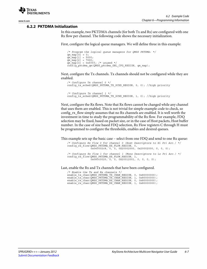
6.2 Example Code
SPRUGR9D+++—January 2012 KeyStone Architecture Multicore Navigator User Guide 6-7Submit Documentation Feedback
Chapter 6—Programming Informationwww.ti.com
6.2.2 PKTDMA InitializationIn this example, two PKTDMA channels (for both Tx and Rx) are configured with one Rx flow per channel. The following code shows the necessary initialization.
First, configure the logical queue managers. We will define three in this example:
/* Program the logical queue managers for QMSS PKTDMA: */ qm_map[0] = 0;
qm_map[1] = 5000;qm_map[2] = 7000;qm_map[3] = 0xffff; /* unused */
config_pktdma_qm(QMSS_pktdma_GBL_CFG_REGION, qm_map);
Next, configure the Tx channels. Tx channels should not be configured while they are enabled.
/* Configure Tx channel 0 */config_tx_sched(QMSS_PKTDMA_TX_SCHD_REGION, 0, 0); //high priority
/* Configure Tx channel 1 */config_tx_sched(QMSS_PKTDMA_TX_SCHD_REGION, 1, 0); //high priority
Next, configure the Rx flows. Note that Rx flows cannot be changed while any channel that uses them are enabled. This is not trivial for simple example code to check, so config_rx_flow simply assumes that no Rx channels are enabled. It is well worth the investment in time to study the programmability of the Rx flow. For example, FDQ selection may be fixed, based on packet size, or in the case of Host packets, Host buffer number. In the case of size based FDQ selection, Rx Flow registers C through H must be programmed to configure the thresholds, enables and desired queues.
This example sets up the basic case – select from one FDQ and send to one Rx queue:/* Configure Rx flow 0 for channel 0 (Host Descriptors to Hi Pri Acc.) */
config_rx_flow(QMSS_PKTDMA_RX_FLOW_REGION, 0, 0x040002c8, 0, 0, 0x20002000, 0x20002000, 0, 0, 0);
/* Configure Rx flow 1 for channel 1 (Mono Descriptors to Lo Pri Acc.) */ config_rx_flow(QMSS_PKTDMA_RX_FLOW_REGION, 1, 0x080c0020, 0, 0, 0x20012001, 0, 0, 0, 0);
Last, enable the Rx and Tx channels that have been configured./* Enable the Tx and Rx channels */
enable_tx_chan(QMSS_PKTDMA_TX_CHAN_REGION, 0, 0x80000000); enable_tx_chan(QMSS_PKTDMA_TX_CHAN_REGION, 1, 0x80000000); enable_rx_chan(QMSS_PKTDMA_RX_CHAN_REGION, 0, 0x80000000); enable_rx_chan(QMSS_PKTDMA_RX_CHAN_REGION, 1, 0x80000000);

6.2 Example Code
6-8 KeyStone Architecture Multicore Navigator User Guide SPRUGR9D+++—January 2012Submit Documentation Feedback
Chapter 6—Programming Information www.ti.com
6.2.3 Normal Infrastructure DMA with AccumulationAt this point, everything has been initialized for the example test case. All that remains to be done is:
1. Pop descriptors from the Tx completion (FDQ) queues.2. Fill the descriptor fields and buffers with some data.3. Push the filled descriptors onto the Tx queues.4. Wait for the accumulators to complete popping the Rx queues and building the
descriptor lists.
The following code will push 8 descriptors into the Tx queues then wait for the results:for (idx = 0; idx < 8; idx ++)
{ Uint32 tmp = pop_queue(5000); host_pkt = (MNAV_HostPacketDescriptor *)(tmp); host_pkt->type_id = MNAV_DESC_ID_HOST; host_pkt->ps_reg_loc = 0; host_pkt->packet_length = 64; host_pkt->psv_word_count = 0; host_pkt->pkt_return_qnum = 0x1000; host_pkt->buffer_len = 64;
host_pkt->next_desc_ptr = NULL; host_pkt->src_tag_lo = 0; //copied to .flo_idx of streaming i/f
/* Add code here to fill the descriptor's buffer */
push_queue(800, 1, 0, tmp);
tmp = pop_queue(5001); mono_pkt = (MNAV_MonolithicPacketDescriptor *)(tmp); mono_pkt->type_id = MNAV_DESC_ID_MONO; mono_pkt->data_offset = 12; mono_pkt->packet_length = 16; mono_pkt->epib = 0; mono_pkt->pkt_return_qnum = 0x1001; mono_pkt->src_tag_lo = 1; //copied to .flo_idx of streaming i/f
/* Add code here to fill the descriptor's buffer */
push_queue(801, 1, 0, tmp); }
/* Burn some time for the accumulators to run. */ testpass = 0; for (idx = 0; idx < 20000; idx ++) { testpass = idx; }
Because no data was loaded into buffers, there is no need to check for that here. But, check to see that the correct descriptors arrived in the resulting host descriptor and monolithic descriptor lists. Note that the descriptors in these lists no longer belong to any queue. It is the host’s responsibility to requeue them.
testpass = 1; /* Check the Host Packet accumulator list. */ for (idx = 0; idx < 8; idx ++) { addr = (Uint32)(host_region + ((idx + 16) * 64)); if (hostList[idx+1] != addr) testpass = 0; }
if (hostList[0] != 8) //check the list count in element 0 testpass = 0;
if (testpass == 1) printf("Host Descriptor Test: PASS\n"); else printf("Host Descriptor Test: FAIL\n");

6.2 Example Code
SPRUGR9D+++—January 2012 KeyStone Architecture Multicore Navigator User Guide 6-9Submit Documentation Feedback
Chapter 6—Programming Informationwww.ti.com
testpass = 1; /* Check the Monolithic Packet accumulator list. */ for (idx = 0; idx < 8; idx ++) { addr = (Uint32)(mono_region + ((idx + 16) * 160)); if (monoList[idx] != addr) testpass = 0; }
if (monoList[8] != 0) //check for the NULL terminator in this list testpass = 0;
if (testpass == 1) printf("Monolithic Descriptor Test: PASS\n"); else printf("Monolithic Descriptor Test: FAIL\n");
6.2.4 Bypass Infrastructure notification with AccumulationIn this mode, the PKTDMA is bypassed because there is no data to transmit (or the data has been placed in a shared memory buffer available to both the source and destination cores). Descriptors will be popped off the Rx FDQs, and pushed directly onto the Rx queues, causing the accumulators to act on them.
Using the same QM Initialization as shown in section 6.2.1 ‘‘QMSS Initialization’’ on page 6-4, and no required PKTDMA initialization, it is possible to pop directly from the Rx FDQ, and push to the accumulation queues and achieve the same results. The descriptors can be uninitialized if desired (because the QM does not look at them), but they can be used to pass information from source to destination.
for (idx = 0; idx < 8; idx ++) { Uint32 tmp = pop_queue(7000); host_pkt = (MNAV_HostPacketDescriptor *)(tmp); host_pkt->type_id = MNAV_DESC_ID_HOST; host_pkt->buffer_ptr = (Uint32)buffers; //this can point to a shared buffer host_pkt->next_desc_ptr = NULL;
push_queue(712, 1, 0, tmp);
tmp = pop_queue(7001); mono_pkt = (MNAV_MonolithicPacketDescriptor *)(tmp); mono_pkt->type_id = MNAV_DESC_ID_MONO; push_queue(32, 1, 0, tmp); }
/* Burn some time for the accumulators to run. */ testpass = 0; for (idx = 0; idx < 20000; idx ++) { testpass = idx; }

6.2 Example Code
6-10 KeyStone Architecture Multicore Navigator User Guide SPRUGR9D+++—January 2012Submit Documentation Feedback
Chapter 6—Programming Information www.ti.com
6.2.5 Channel TeardownTo perform a channel teardown, the host must do the following:
1. When the host desires to teardown a channel (either Rx or Tx), it writes a 1 to the teardown field of the corresponding Rx or Tx Channel Global Configuration Register for that channel. The host should not disable the channel by writing a 0 to the enable field of this register. The PKTDMA will do this when finished with the teardown.
When the PKTDMA detects the teardown bit is set, it will:
The host detects the teardown is complete by examining the Rx/Tx Channel Global Configuration Register to check the enable status.
6.2.6 Using the Four Logical Queue ManagersThe PKTDMA does not view the physical 8192 queue Queue Manager (QM) directly, but as (up to) four logical 4095 queue managers that map into the physical QM. For this reason, all references to QM are made through pairs of qmgr:qnum fields. The 2-bit qmgr field ranges from 0 to 3, and the 12-bit qnum field ranges from 0 to 0xFFE (0xFFF is reserved). The configuration of the four logical QMs is determined by the programming of the QMn Base Address Registers in each PKTDMA’s global configuration region.
The simplest use case is to nothing at all, i.e. do not program any of the QMn Base Address Registers. In this case, the PKTDMA will have use of a single queue manager (QM 0), which will map to queues 0 through 4094. This is because the reset value of QM0 points to the base of the queues region inside the QMSS.
The next simplest use case is to program QM 1 to point to physical queue 4096 (which is done by programming the QM1 Base Address Register to 4096 × 16 bytes beyond the base of the QMSS queues region). In this case, all 8192 queues are available, except for 4095 and 8191 (which would have a qnum value of 0xFFF).
Additional benefits for this use case are: • The 14-bit qmgr+qnum field can be dealt with as a single field• There is no logical to physical translation required for software
Tx Teardown Rx Teardown
• Allow the current packet to complete normally.• Clear the channel enable bit in the Tx Channel Global Configuration
Register. The teardown bit will remain set as an indication that a teardown was performed.
• Signals the attached peripheral (rx_teardown_req) that a teardown was requested by the Host.
• Waits for the peripheral to acknowledge (rx_teardown_ack). Notes:– During this time, processing continues normally.– In some peripherals, rx_teardown_req and rx_teardown_ack are tied
together in loopback.• Following ack, the current packet is allowed to complete normally.• Clear the channel enable in the Rx Channel Global Configuration
Register. The teardown bit will remain set as an indication that a teardown was performed.

6.2 Example Code
SPRUGR9D+++—January 2012 KeyStone Architecture Multicore Navigator User Guide 6-11Submit Documentation Feedback
Chapter 6—Programming Informationwww.ti.com
Another use case would be to create four 2047 queue managers, or four non-evenly sized queue managers. Note that in any of these cases, there is overlap between two or more logical QMs, making it possible to refer to the same physical queue by more than one qmgr:qnum pair. The difficulty here for software is that it must create a queue mapping for the PKTDMA. For example:
1. QM0 maps to queues 0...40942. QM1 maps to queues 5000...81913. QM2 maps to queues 7000...8191
If an Rx FDQ is created in physical queue 7000, the host must push descriptors to queue 7000, but to program the Rx Flow, the qmgr:qnum pair used must be 2:000. Likewise, if a Tx FDQ is created in physical queue 5010, the packet return qmgr:qnum pair in the descriptor must be set to 1:00a. Also, note that in this configuration, physical queues 4095 through 4999 are not accessible by the PKTDMA.

6.3 Programming Overrides
6-12 KeyStone Architecture Multicore Navigator User Guide SPRUGR9D+++—January 2012Submit Documentation Feedback
Chapter 6—Programming Information www.ti.com
6.3 Programming OverridesThe following is a list of ways to override the default programming methods. The programmer needs to pay attention to these, because if done incorrectly the PKTDMA may not function as expected and may be difficult to debug.
1. Streaming I/F Overrides:a. flow_index. A value of 0xFFFF (or a value >= the number of Rx Flows) will
cause the Rx DMA to use the channel (thread) number for flow_index. So, an Rx Flow is always used, even if not directly specified.
b. dest_qnum. A value of 0x1FFF is the normal, non-override value. When set to this, the Rx DMA will use the RX_DEST_QNUM/QMGR fields in the defined Rx Flow. Any other value will override the Rx Flow value.
2. Loopback Override: To loop Tx descriptor payloads to the Rx DMA (such as in Infrastructure transfers), set the SOURCE TAG – LO field in the descriptor to the Rx flow number that should be used by the Rx DMA. It will be passed through the Streaming I/F in the flow index parameter.

6.4 Programming Errors
SPRUGR9D+++—January 2012 KeyStone Architecture Multicore Navigator User Guide 6-13Submit Documentation Feedback
Chapter 6—Programming Informationwww.ti.com
6.4 Programming ErrorsProgramming Multicore Navigator’s various components can be tedious, and if done incorrectly, may cause dataflow to stop with no alert given. Here are a few things to watch for:
1. Queue manager:a. Pushing the same descriptor into the same queue more than once. This
corrupts the linking RAM, making it inconsistent with the rest of the queue manager’s internal data for the queue.
b. Pushing the same descriptor into more than one queue at the same time. This also will corrupt the linking RAM, causing a loss of data.
c. Pushing any descriptor address to a queue where the address is not contained within a descriptor memory region that has been programmed into the queue manager.
d. Pushing a descriptor address that is not on an N-word boundary within a programmed memory region, where N-word is the programmed descriptor size.
e. Linking host descriptors in an Rx FDQ. This should never be done, because the Rx DMA will pop descriptors and link them together automatically. The Rx DMA does not differentiate between host packet and host buffer type descriptors (it will fill in the fields to create what it needs).
f. Incorrect host descriptor linking for Tx. The host should create and push a host packet descriptor for each packet. If additional host buffer descriptors are needed because the packet length is too large for the host packet's buffer, then host buffer descriptors should be linked to the Host Packet as needed.
g. Programming overlapping descriptor memory regions.
2. PKTDMA:a. An Rx flow must be programmed for every Rx transaction. If the application
is directly (or indirectly) driving the PKTDMA’s Rx Streaming I/F (infrastructure tests is an example) and a valid Rx flow ID is not specified, the Rx DMA will substitute the channel number and use it for the Rx flow ID. To specify the Rx flow from the Tx descriptor, fill the SOURCE TAG LO field with the desired Rx flow number.
b. Trying to reconfigure a Tx channel while it is still enabled, or reprogramming an Rx flow while any channel that uses it is still enabled. This is a difficult-to-find error.
3. Accumulator:a. Mismatching the list count mode or list entry size in the accumulator program
with how the host code reads the list.b. Not sizing the list correctly. If 100 entries in the list are desired, and a 2-word
entry size (regs C and D) is programmed, then the list needs to be sized appropriately: (100 + 1) × 2 × 2 = 404 words. The pong side begins at word 202.

6.5 Questions and Answers
6-14 KeyStone Architecture Multicore Navigator User Guide SPRUGR9D+++—January 2012Submit Documentation Feedback
Chapter 6—Programming Information www.ti.com
6.5 Questions and AnswersThis section contains frequently asked questions and responses to them.
Question: How does descriptor accumulator polling work?All high-priority accumulator channels are continuously polled. After each loop through all of the high-priority channels, one of the low-priority channels is polled. The timers are used only for the interrupt pacing modes.
Question: How should Rx flows and channels be used?The first step is to see that the Rx DMA is driven from the Rx streaming I/F. When each part of a packet is received from the streaming I/F, it contains a channel number. This number will not change for the entire packet’s reception (and once a packet starts on a channel, that channel is dedicated to that packet until it completes). The channel number is determined by the programming of the peripheral (because it is the peripheral that drives the Rx streaming I/F). For the infrastructure PKTDMA, it is always the same as the Tx channel number because the streaming I/F is connected in loopback.
Next, the initial transmission of the packet to the Rx DMA contains some sideband data. One of these parms is the flow_id. Because the flow_id comes as parametric data with the packet, it can change packet by packet, and is not related to channel number in any way. This is the reason why there are more flows than channels — in case there is a need to use more than one flow for a stream of packets.
How the flow_id is determined also varies by peripheral. The peripherals provide a mechanism to set the flow_id; it may be a register, or a value in protocol-specific data. For the infrastructure PKTDMA, it is passed from the Tx side using the SRC_TAG_LO field in the Tx descriptor. But it is a value that you choose.
An example from the LTE Demo project: At one point in the processing, an output of the FFTC block is in this form: A B C B A, where A is a range of bytes that are not needed, B contains data to be processed on core 1, and C contains data to be processed on core 2. The setup for this is done so that all data lands in the LL2 of the core that needs to process it:
First, FDQs are constructed (at initialization) with host descriptors and buffers in each core’s LL2.
Next, (at runtime, prior to the FFTC running) another highly specialized FDQ is built such that it is loaded with exactly five descriptors:
• The first and fifth point to a single garbage buffer – for part A• The second and fourth point to buffers in core 1’s LL2 – for part B• The third points to a buffer in core 2’s LL2 – for part C
Descriptors 2, 3, and 4 are popped from the LL2 FDQs from cores 1, 2, and 1, respectively. Each buffer size is set to the exact number of bytes for the A, B, and C fields so that as the Rx DMA processes the data, each descriptor in this specialized FDQ is popped at the right time, loaded with the correct data, and linked to the previous buffer to create a single host descriptor.
The Rx flow setting is simple: One Rx FDQ, and the Rx destination queue will be an accumulation channel so that core 1 will be notified when the FFTC results are ready.

6.5 Questions and Answers
SPRUGR9D+++—January 2012 KeyStone Architecture Multicore Navigator User Guide 6-15Submit Documentation Feedback
Chapter 6—Programming Informationwww.ti.com
The choice of Rx channel number and Rx flow number for the FFTC is arbitrary — any of the four channels and eight flows is as good as any of the others. It depends on how the FFTC is programmed. When using the Multicore Navigator LLDs, they can determine which channel and flow to use (it will select one and pass back a handle to it).
That is a creative example of how to take the output of a peripheral and use Multicore Navigator resources to get the data to its destination(s) efficiently. The power of the Multicore Navigator is that this problem can be solved in many different ways.
Question: How does a peripheral choose which Rx channel to use?Each Multicore Navigator peripheral has it’s own method:
• QMSS and FFTC — the Rx channel used is the same as the Tx channel that drives it.
• SRIO — The SRIO picks an Rx channel from those that are enabled. See the SRIO User Guide for more details.
• AIF2 — For DIO (WCDMA), Rx channel must be channel number 128. For channels 0 through 127, the Rx channel and Rx flow numbers are always the same as the DB channel number.
• PA — Packet classification information is associated with a destination queue and flow number. For example, the PA is instructed to match dest mac = x, dest IP = y, dest TCP port = z, and then it sends the packet to queue A using flow B. But the channels are hard mapped to streaming endpoints within submodules. These submodules are either PDSPs or else they are encryption/authentication blocks.
So, it is not a matter of the peripheral finding an enabled channel, but rather the peripheral using a specific channel whether or not it is enabled (and if not enabled, no data will pass through).
Question: I’m interested in the case where the infrastructure PKTDMA is moving data from one core’s L2 to a second core’s L2. What I do not understand is how does the TX queue become tied to a TX channel for that case and how does that connect with the RX channel and queue?With all the Tx DMAs, there is a one-to-one HW mapping between a queue number and a Tx channel. In the QMSS case, queue 800 maps to Tx channel 0, 801 to 1, etc. And, the QMSS loopback connection causes Tx channel X to send data to Rx channel X. So, to use channel 0, open (LLD terminology) queue 800, open Tx channel 0, Rx channel 0, an Rx Flow, and whatever Rx Q, Rx FDQ, and Tx FDQ queues that should be used. Note that the Tx descriptor defines the Tx FDQ (and Rx Flow) to be used, and the Rx Flow defines the Rx Q and Rx FDQ.
Once everything is properly initialized, all that must be done is pop a descriptor from the Tx FDQ, fill it with data and push it to queue 800. It will flow through the Tx DMA, the Streaming I/F, the Rx DMA and be pushed to the Rx Q. To make this transfer data from core A’s L2 to core B’s L2, the Tx FDQ’s descriptors (or host buffers) must be in a QMSS memory region located in core A’s L2, and the Rx FDQ’s descriptors (or host buffers) must be in a QMSS memory region located in core B’s L2.

6.5 Questions and Answers
6-16 KeyStone Architecture Multicore Navigator User Guide SPRUGR9D+++—January 2012Submit Documentation Feedback
Chapter 6—Programming Information www.ti.com
Question: Can I push multiple descriptor types to the same queue?From the Queue Manager’s perspective, yes. The QM does not care what is stored at the descriptor addresses (it does not have to be a descriptor - but it is an error to push anything other than a valid descriptor through a PKTDMA). From the PKTDMA’s perspective, it depends. The Tx DMA handles each packet separately, so there is no problem pushing host and monolithic descriptors into the same Tx queue. On the Rx side, each Rx FDQ should be populated with one type of descriptor, because the Rx DMA handles host and monolithic descriptors differently.
Question: What happens when no configured RX packet queue has a packet that is large enough to hold the data?It depends. For monolithic packet mode, the Rx DMA assumes the descriptor is big enough, and will overwrite adjacent memory if it isn't. For Host packet mode, the Rx DMA will keep popping descriptors and linking them together until it has buffered all the data or run out of descriptors (Rx starvation).
Question: What happens when the RX queue of the receiving flow is out of buffers?This condition is called buffer starvation. The action of the Rx DMA is configurable, depending on the setting of the rx_error_handling field of the Rx Flow that is currently in use. If the field is clear, the packet will be dropped. If set, the Rx DMA will re-try at a rate specified by the Performance Config Register.
Question: What happens when a packet is received and the specified flow configuration is not set up? Is there any indication that the transmission did not succeed?If the channel has been enabled, the Rx DMA will use reset values for the Rx flow if it has not been programmed. There is no error status; but a core can detect the problem in a couple of ways:
1. Set a timeout and read the Rx/Rx FDQ descriptor counts,2. Use pacing mode last interrupt with the Accumulator and examine cases where
the list is empty,3. Read the QMSS' INTD Status Register #4 to see if a starvation interrupt occurred
(if the flow is using reset values, it will use queue 0 as the FDQ),4. Program a threshold for the Rx queue(s) and read the Queue Status RAM.
Question: Is there any situation that can cause packet transfer over infrastructure queues to cause packets to be delivered out-of-order or not at all (but following packets will be transferred)? Out-of-order reception is not possible for the infrastructure PKTDMA, due to the loopback connection of the Streaming I/F. Dropped packets are possible due to errors on the Rx side. Dropped packets can be detected by using the tag fields to send a sequence number through to the Rx descriptor.
Question: Are peripherals limited by the 4 level Tx DMA round robin scheduling? No. It is true that the Tx DMA by itself will starve lower priority levels if flooded by higher priority packets. However, it is possible for the IP to disable the higher priority channels at the Streaming I/F level, thereby allowing lower priority channels to run. The FFTC is a case of one IP that does this.

6.5 Questions and Answers
SPRUGR9D+++—January 2012 KeyStone Architecture Multicore Navigator User Guide 6-17Submit Documentation Feedback
Chapter 6—Programming Informationwww.ti.com
Question: If I'm not going to use a Multicore Navigator feature, can I use its resources for other purposes?In several cases, yes. For example, if you do not plan to use Low Priority Accumulation, you can use queues 0 to 511 as general purpose queues, and you can also use the QMSS INTD to generate events normally associated with the Low Priority Accumulator to the DSPs for sync barrier purposes. You only need to make sure that the feature (Low Priority Accumulation in this example) is not enabled.
Question: Can I assign priorities to queues?Not with the Queue Manager alone. The queue management of each queue is independent, and one queue does not affect another. The Tx DMA allows a 4 level priority scheme to be imposed, and there are other methods for creating priority, such as external schedulers.
Question: Should memory regions be specified in ascending order?Yes. Memory region base addresses must be set in ascending address order, i.e. region 0 must be at a lower address than region 1, region 1 must be at a lower address than region 2, etc. This requires extra planning when configuring regions in LL2, MSMC and DDR.
Question: Is the mapping of channel, queue and interrupt event fixed or can it be modified?The mapping of channels to events is fixed. The mapping of queue number to channel number is fixed only for queues that drive queue_pend signals. This means that accumulator queue numbers may be changed (the queues shown are the suggested mapping).

6.5 Questions and Answers
6-18 KeyStone Architecture Multicore Navigator User Guide SPRUGR9D+++—January 2012Submit Documentation Feedback
Chapter 6—Programming Information www.ti.com

SPRUGR9D+++—January 2012 KeyStone Architecture Multicore Navigator User Guide A-1Submit Documentation Feedback
Appendix A
Example Code Utility Functions
The following functions are simple, low-level utility functions that directly program the necessary Multicore Navigator hardware registers. The addresses and other types are listed in the following appendices.
/* This function programs a QM memory region. */void set_memory_region(Uint16 regn, Uint32 addr, Uint32 indx, Uint32 setup){ Uint32 *reg;
reg = (Uint32 *)(QM_DESC_REGION + QM_REG_MEM_REGION_BASE + (regn * 16)); *reg = addr;
reg = (Uint32 *)(QM_DESC_REGION + QM_REG_MEM_REGION_INDEX + (regn * 16)); *reg = indx;
/* See register description for programming values. */ reg = (Uint32 *)(QM_DESC_REGION + QM_REG_MEM_REGION_SETUP + (regn * 16)); *reg = setup;}
/* This function programs a QM Link RAM. */void set_link_ram(Uint16 ram, Uint32 addr, Uint32 count){ Uint32 *reg;
reg = (Uint32 *)(QM_CTRL_REGION + QM_REG_LINKRAM_0_BASE + (ram * 8)); *reg = addr;
if (ram == 0) { reg = (Uint32 *)(QM_CTRL_REGION + QM_REG_LINKRAM_0_SIZE); *reg = count; }}
/* This function pushes descriptor info to a queue. * mode parameter: 1 = write reg D only. * 2 = write regs C and D.** It turns out the VBUSM is more efficient to push to than VBUSP,* and also allows for atomic c+d pushes.*/void push_queue(Uint16 qn, Uint8 mode, Uint32 c_val, Uint32 d_val){#ifdef USE_VBUSM
if (mode == 2) { uint64_t *reg;
reg = (uint64_t *)(QM_QMAN_VBUSM_REGION + QM_REG_QUE_REG_C + (qn * 16));
#ifdef _BIG_ENDIAN

A-2 KeyStone Architecture Multicore Navigator User Guide SPRUGR9D+++—January 2012Submit Documentation Feedback
Appendix A—Example Code Utility Functions www.ti.com
*reg = ((uint64_t)c_val << 32) | d_val; #else *reg = ((uint64_t)d_val << 32) | c_val; #endif } else { Uint32 *reg; reg = (Uint32 *)(QM_QMAN_VBUSM_REGION + QM_REG_QUE_REG_D + (qn * 16)); *reg = d_val; }#else Uint32 *reg;
if (mode == 2) { reg = (Uint32 *)(QM_QMAN_REGION + QM_REG_QUE_REG_C + (qn * 16)); *reg = c_val; }
reg = (Uint32 *)(QM_QMAN_REGION + QM_REG_QUE_REG_D + (qn * 16)); *reg = d_val;#endif}
/* This function pops a descriptor address from a queue. */Uint32 pop_queue(Uint16 qn){ Uint32 *reg; Uint32 value;
reg = (Uint32 *)(QM_QMAN_REGION + QM_REG_QUE_REG_D + (qn * 16)); value = *reg;
return(value);}
/* This function moves a source queue to a destination queue. If * headtail = 0, the source queue is appended to the tail of the * dest queue. If 1, it is appended at the head. */void divert_queue(Uint16 src_qn, Uint16 dest_qn, Uint8 headtail){ Uint32 *reg; Uint32 value;
reg = (Uint32 *)(QM_CTRL_REGION + QM_REG_QUE_DIVERSION);
value = (headtail << 31) + (dest_qn << 16) + src_qn; *reg = value;
return;}
/* This function pops a queue until it is empty. If *list is not NULL, * it will return the list of descriptor addresses and the count. */void empty_queue(Uint16 qn, Uint32 *list, Uint32 *listCount){ Uint32 *reg; Uint32 value; Uint16 idx; Uint32 count;
reg = (Uint32 *)(QM_PEEK_REGION + QM_REG_QUE_REG_A + (qn * 16)); count = *reg; //read the descriptor count *listCount = count;
reg = (Uint32 *)(QM_QMAN_REGION + QM_REG_QUE_REG_D + (qn * 16));
for (idx = 0; idx < count; idx ++) { value = *reg; if (list != NULL) { list[idx] = value; } }}

SPRUGR9D+++—January 2012 KeyStone Architecture Multicore Navigator User Guide A-3Submit Documentation Feedback
Appendix A—Example Code Utility Functionswww.ti.com
/* This function returns the byte count of a queue. */Uint32 get_byte_count(Uint16 qn){ Uint32 *reg; Uint32 count;
reg = (Uint32 *)(QM_PEEK_REGION + QM_REG_QUE_REG_B + (qn * 16)); count = *reg;
return(count);}
/* This function returns the descriptor count of a queue. */Uint32 get_descriptor_count(Uint16 qn){ Uint32 *reg; Uint32 count;
reg = (Uint32 *)(QM_PEEK_REGION + QM_REG_QUE_REG_A + (qn * 16)); count = *reg;
return(count);}
/* This function sets a queue threshold for queue monitoring purposes. */void set_queue_threshold(Uint16 qn, Uint32 value){ Uint32 *reg;
reg = (Uint32 *)(QM_PEEK_REGION + QM_REG_QUE_STATUS_REG_D + (qn * 16)); *reg = value;}
/* This function programs a Hi or Lo Accumulator channel. */void program_accumulator(Uint16 pdsp, Qmss_AccCmd *cmd){ Uint16 idx; Uint32 *tmplist; Uint32 *reg;
if (pdsp == 1) reg = (Uint32 *)(PDSP1_CMD_REGION + 4*4); //point to last word else reg = (Uint32 *)(PDSP2_CMD_REGION + 4*4); //point to last word
tmplist = ((uint32_t *) cmd) + 4; //write first word last
for (idx = 0; idx < 5; idx ++) { *reg-- = *tmplist--; }
/* wait for the command byte to clear. */reg++;
do { result = (*reg & 0x0000ff00) >> 8; } while (result != 0);}
/* This function disables a Hi or Lo Accumulator program. */void disable_accumulator(Uint16 pdsp, Uint16 channel){ Uint16 idx; Uint32 *tmplist; Uint32 *reg; Qmss_AccCmd cmd;
memset(&cmd, 0, sizeof(Qmss_AccCmd)); cmd.channel = channel; cmd.command = QMSS_ACC_CMD_DISABLE;
if (pdsp == 1) reg = (Uint32 *)(PDSP1_CMD_REGION + 4*4); //point to last word else reg = (Uint32 *)(PDSP2_CMD_REGION + 4*4); //point to last word

A-4 KeyStone Architecture Multicore Navigator User Guide SPRUGR9D+++—January 2012Submit Documentation Feedback
Appendix A—Example Code Utility Functions www.ti.com
tmplist = ((uint32_t *) &cmd) + 4; //write first word last
for (idx = 0; idx < 5; idx ++) { *reg-- = *tmplist--; }}
/* This function writes a new value to a PDSP's firmware * Time is specified in usec, then converted to the hardware * expect value assuming a 350Mhz QMSS sub-system clock. */void set_firmware_timer(Uint16 pdsp, Uint16 time){ Uint16 idx; Uint32 *tmplist; Uint32 *reg; Qmss_AccCmd cmd;
memset(&cmd, 0, sizeof(Qmss_AccCmd)); cmd.queue_mask = (time * 175); //convert usec to hw val cmd.command = QMSS_ACC_CMD_TIMER;
if (pdsp == 1) reg = (Uint32 *)(PDSP1_CMD_REGION + 4); //point to 2nd word else reg = (Uint32 *)(PDSP2_CMD_REGION + 4); //point to 2nd word
tmplist = ((uint32_t *) &cmd) + 1; //write 2nd word last
*reg-- = *tmplist--; *reg = *tmplist;}
/* This function programs base addresses for the four logical* queue managers that a PKTDMA may setup. Use a value of 0xffff* if you don't want to set value into QM base addr reg. N. */void config_pktdma_qm(Uint32 base, Uint16 *physical_qnum){
Uint16 idx;Uint32 qm_base;Uint32 *reg;
for (idx = 0; idx < 4; idx ++){
if (physical_qnum[idx] != 0xffff){
qm_base = QM_QMAN_VBUSM_REGION + (physical_qnum[idx] * 16);
reg = (Uint32 *)(base + PKTDMA_REG_QM0_BASE_ADDR + (idx * 4));*reg = qm_base;
}}
}
/* This function enables/disables internal loopback mode for a pktDMA. * By default, it should be enabled for QMSS, disabled for all others. */void config_pktdma_loopback(Uint32 base, Uint8 enable){ Uint32 *reg;
reg = (Uint32 *)(base + PKTDMA_REG_EMULATION_CTRL);
if (enable) *reg = 0x80000000; else *reg = 0x0;}
/* This function sets the packet retry timeout. * A value of 0 disables the retry feature. */void config_pktdma_retry_timeout(Uint32 base, Uint16 timeout){ Uint32 *reg;

SPRUGR9D+++—January 2012 KeyStone Architecture Multicore Navigator User Guide A-5Submit Documentation Feedback
Appendix A—Example Code Utility Functionswww.ti.com
Uint32 val;
reg = (Uint32 *)(base + PKTDMA_REG_PERFORMANCE_CTRL);
val = *reg & 0xFFFF0000;
*reg = val | timeout;}
/* This function disables a TX DMA channel, then configures it. */void config_tx_chan(Uint32 base, Uint16 chan, Uint32 return_q){ Uint32 *reg;
reg = (Uint32 *)(base + PKTDMA_REG_TX_CHAN_CFG_A + (chan * 32)); *reg = 0; //disable the channel
reg = (Uint32 *)(base + PKTDMA_REG_TX_CHAN_CFG_B + (chan * 32)); *reg = return_q;}
/* This function configures priority of a TX DMA channel */void config_tx_sched(Uint32 base, Uint16 chan, Uint32 priority){ Uint32 *reg;
reg = (Uint32 *)(base + PKTDMA_REG_TX_SCHED_CHAN_CFG + (chan * 4)); *reg = priority;}
/* This function configures an RX DMA channel flow. */void config_rx_flow(Uint32 base, Uint16 flow, Uint32 a, Uint32 b, Uint32 c, Uint32 d, Uint32 e, Uint32 f, Uint32 g, Uint32 h){ Uint32 *reg;
reg = (Uint32 *)(base + PKTDMA_REG_RX_FLOW_CFG_A + (flow * 32)); *reg = a;
reg = (Uint32 *)(base + PKTDMA_REG_RX_FLOW_CFG_B + (flow * 32)); *reg = b;
reg = (Uint32 *)(base + PKTDMA_REG_RX_FLOW_CFG_C + (flow * 32)); *reg = c;
reg = (Uint32 *)(base + PKTDMA_REG_RX_FLOW_CFG_D + (flow * 32)); *reg = d;
reg = (Uint32 *)(base + PKTDMA_REG_RX_FLOW_CFG_E + (flow * 32)); *reg = e;
reg = (Uint32 *)(base + PKTDMA_REG_RX_FLOW_CFG_F + (flow * 32)); *reg = f;
reg = (Uint32 *)(base + PKTDMA_REG_RX_FLOW_CFG_G + (flow * 32)); *reg = g;
reg = (Uint32 *)(base + PKTDMA_REG_RX_FLOW_CFG_H + (flow * 32)); *reg = h;}
/* This function writes an RX DMA channel's enable register. */void enable_rx_chan(Uint32 base, Uint16 chan, Uint32 value){ Uint32 *reg;
reg = (Uint32 *)(base + PKTDMA_REG_RX_CHAN_CFG_A + (chan * 32)); *reg = value;}
/* This function writes a TX DMA channel's enable register. */void enable_tx_chan(Uint32 base, Uint16 chan, Uint32 value){ Uint32 *reg;
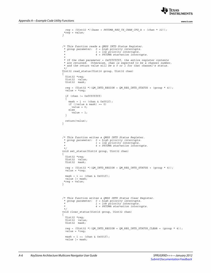
A-6 KeyStone Architecture Multicore Navigator User Guide SPRUGR9D+++—January 2012Submit Documentation Feedback
Appendix A—Example Code Utility Functions www.ti.com
reg = (Uint32 *)(base + PKTDMA_REG_TX_CHAN_CFG_A + (chan * 32)); *reg = value;}
/* This function reads a QMSS INTD Status Register. * group parameter: 0 = high priority interrupts. * 1 = low priority interrupts. * 4 = PKTDMA starvation interrupts. * * If the chan parameter = 0xffffffff, the entire register contents * are returned. Otherwise, chan is expected to be a channel number, * and the return value will be a 0 or 1 for that channel's status. */Uint32 read_status(Uint16 group, Uint32 chan){ Uint32 *reg; Uint32 value; Uint32 mask;
reg = (Uint32 *)(QM_INTD_REGION + QM_REG_INTD_STATUS + (group * 4)); value = *reg;
if (chan != 0xffffffff) { mask = 1 << (chan & 0x001f); if ((value & mask) == 0) value = 0; else value = 1; }
return(value);}
/* This function writes a QMSS INTD Status Register. * group parameter: 0 = high priority interrupts. * 1 = low priority interrupts. * 4 = PKTDMA starvation interrupts. */void set_status(Uint16 group, Uint32 chan){ Uint32 *reg; Uint32 value; Uint32 mask;
reg = (Uint32 *)(QM_INTD_REGION + QM_REG_INTD_STATUS + (group * 4)); value = *reg;
mask = 1 << (chan & 0x001f); value |= mask; *reg = value;}
/* This function writes a QMSS INTD Status Clear Register. * group parameter: 0 = high priority interrupts. * 1 = low priority interrupts. * 4 = PKTDMA starvation interrupts. */void clear_status(Uint16 group, Uint32 chan){ Uint32 *reg; Uint32 value; Uint32 mask;
reg = (Uint32 *)(QM_INTD_REGION + QM_REG_INTD_STATUS_CLEAR + (group * 4)); value = *reg;
mask = 1 << (chan & 0x001f); value |= mask;

SPRUGR9D+++—January 2012 KeyStone Architecture Multicore Navigator User Guide A-7Submit Documentation Feedback
Appendix A—Example Code Utility Functionswww.ti.com
*reg = value;}
/* This function reads a QMSS INTD Int Count Register. * Reading has no effect on the register. * "intnum" is: 0..31 for High Pri interrupts * 32..47 for Low Pri interrupts * 48..49 for PKTDMA Starvation interrupts */Uint32 read_intcount(Uint16 intnum){ Uint32 *reg; Uint32 value;
reg = (Uint32 *)(QM_INTD_REGION + QM_REG_INTD_INT_COUNT + (intnum * 4)); value = *reg;
return(value);}
/* This function reads a QMSS INTD Int Count Register. * Writing will cause the written value to be subtracted from the register. * "intnum" is: 0..31 for High Pri interrupts * 32..47 for Low Pri interrupts * 48..49 for PKTDMA Starvation interrupts */void write_intcount(Uint16 intnum, Uint32 val){ Uint32 *reg;
reg = (Uint32 *)(QM_INTD_REGION + QM_REG_INTD_INT_COUNT + (intnum * 4)); *reg = val;}
/* This function writes a QMSS INTD EOI Register. Values to write are: 0 or 1: PKTDMA starvation interrupts, 2 to 33: High Pri interrupts, 34 to 49: Low Pri interrupts. * Writing one of these values will clear the corresponding interrupt. */void write_eoi(Uint32 val){ Uint32 *reg;
reg = (Uint32 *)(QM_INTD_REGION + QM_REG_INTD_EOI); *reg = val;}
/* This function writes a QMSS PDSP Control Register. */void pdsp_control(Uint16 pdsp, Uint32 val){ Uint32 *reg;
if (pdsp == 1) reg = (Uint32 *)(PDSP1_REG_REGION + QM_REG_PDSP_CONTROL); else reg = (Uint32 *)(PDSP2_REG_REGION + QM_REG_PDSP_CONTROL);
*reg = val;}
/* This function enables QMSS PDSP n. */void pdsp_enable(Uint16 pdsp){ Uint32 *reg; Uint32 tmp;
if (pdsp == 1)

A-8 KeyStone Architecture Multicore Navigator User Guide SPRUGR9D+++—January 2012Submit Documentation Feedback
Appendix A—Example Code Utility Functions www.ti.com
reg = (Uint32 *)(PDSP1_REG_REGION + QM_REG_PDSP_CONTROL); else reg = (Uint32 *)(PDSP2_REG_REGION + QM_REG_PDSP_CONTROL);
tmp = *reg; tmp |= 0x02; *reg = tmp;}
/* This function disables QMSS PDSP n. */void pdsp_disable(Uint16 pdsp){ Uint32 *reg; Uint32 tmp;
if (pdsp == 1) reg = (Uint32 *)(PDSP1_REG_REGION + QM_REG_PDSP_CONTROL); else reg = (Uint32 *)(PDSP2_REG_REGION + QM_REG_PDSP_CONTROL);
tmp = *reg; tmp &= 0xfffffffd; *reg = tmp;}
/* This function returns true if QMSS PDSP n is running. */Uint8 pdsp_running(Uint16 pdsp){ Uint32 *reg;
if (pdsp == 1) reg = (Uint32 *)(PDSP1_REG_REGION + QM_REG_PDSP_CONTROL); else reg = (Uint32 *)(PDSP2_REG_REGION + QM_REG_PDSP_CONTROL);
return(*reg & 0x00008000);}
/* This function controls the PDSP to load firmware to it. */void pdsp_download_firmware(Uint16 pdsp, Uint8 *code, Uint32 size){ Uint16 idx; Uint32 value; Uint32 *reg;
/* Reset PDSP 1 */ pdsp_disable(pdsp);
/* Confirm PDSP has halted */ do { value = pdsp_running(pdsp); } while (value == 1);
/* Download the firmware */ if (pdsp == 1) memcpy ((void *)PDSP1_IRAM_REGION, code, size); else memcpy ((void *)PDSP2_IRAM_REGION, code, size);
/* Use the command register to sync the PDSP */ if (pdsp == 1) reg = (Uint32 *)(PDSP1_CMD_REGION); else reg = (Uint32 *)(PDSP2_CMD_REGION); *reg = 0xffffffff;
/* Wait to the memory write to land */ for (idx = 0; idx < 20000; idx++) { value = *reg; if (value == 0xffffffff) break; }
/* Reset program counter to zero, and clear Soft Reset bit. */ if (pdsp == 1) reg = (Uint32 *)(PDSP1_REG_REGION + QM_REG_PDSP_CONTROL); else

SPRUGR9D+++—January 2012 KeyStone Architecture Multicore Navigator User Guide A-9Submit Documentation Feedback
Appendix A—Example Code Utility Functionswww.ti.com
reg = (Uint32 *)(PDSP2_REG_REGION + QM_REG_PDSP_CONTROL);
value = *reg; *reg = value & 0x0000fffe; //PC reset is in upper 16 bits, soft reset in bit 0
/* Enable the PDSP */ pdsp_enable(pdsp);
/* Wait for the command register to clear */ if (pdsp == 1) reg = (Uint32 *)(PDSP1_CMD_REGION); else reg = (Uint32 *)(PDSP2_CMD_REGION); do { value = *reg; } while (value != 0);}

A-10 KeyStone Architecture Multicore Navigator User Guide SPRUGR9D+++—January 2012Submit Documentation Feedback
Appendix A—Example Code Utility Functions www.ti.com

SPRUGR9D+++—January 2012 KeyStone Architecture Multicore Navigator User Guide B-1Submit Documentation Feedback
Appendix B
Example Code Types
The following type definitions are referenced by the programming examples above. For Big Endian applications, they should be compiled with _BIG_ENDIAN defined.//Define the Accumulator Command Interface Structure#ifdef _BIG_ENDIANtypedef struct{ uint32_t retrn_code:8; //0=idle, 1=success, 2-6=error uint32_t un1:8; uint32_t command:8; //0x80=disable, 0x81=enable, 0=firmware response uint32_t channel:8; //0 to 47 or 0 to 15
uint32_t queue_mask; //(multi-mode only) bit 0=qm_index queue
uint32_t list_address; //address of Host ping-pong buffer
uint32_t max_entries:16;//max entries per list uint32_t qm_index:16; //qnum to monitor (multiple of 32 for multimode)
uint32_t un2:8; uint32_t cfg_un:2; uint32_t cfg_multi_q:1; //0=single queue mode, 1=multi queue mode uint32_t cfg_list_mode:1;//0=NULL terminate, 1=entry count mode uint32_t cfg_list_size:2;//0="D" Reg, 1="C+D" regs, 2="A+B+C+D" uint32_t cfg_int_delay:2;//0=none, 1=last int, 2=1st new, 3=last new uint32_t timer_count:16;//number of 25us timer ticks to delay int} Qmss_AccCmd;#elsetypedef struct{ uint32_t channel:8; //0 to 47 or 0 to 15 uint32_t command:8; //0x80=disable, 0x81=enable, 0=firmware response uint32_t un1:8; uint32_t retrn_code:8; //0=idle, 1=success, 2-6=error
uint32_t queue_mask; //(multi-mode only) bit 0=qm_index queue
uint32_t list_address; //address of Host ping-pong buffer
uint32_t qm_index:16; //qnum to monitor (multiple of 32 for multimode) uint32_t max_entries:16;//max entries per list
uint32_t timer_count:16;//number of 25us timer ticks to delay int uint32_t cfg_int_delay:2;//0=none, 1=last int, 2=1st new, 3=last new uint32_t cfg_list_size:2;//0="D" Reg, 1="C+D" regs, 2="A+B+C+D" uint32_t cfg_list_mode:1;//0=NULL terminate, 1=entry count mode uint32_t cfg_multi_q:1; //0=single queue mode, 1=multi queue mode uint32_t cfg_un:2; uint32_t un2:8;} Qmss_AccCmd;#endif

B-2 KeyStone Architecture Multicore Navigator User Guide SPRUGR9D+++—January 2012Submit Documentation Feedback
Appendix B—Example Code Types www.ti.com
/*******************************************************************//* Define the bit and word layouts for the Host Packet Descriptor. *//* For a Host Packet, this is used for the first descriptor only. *//*******************************************************************/#ifdef _BIG_ENDIANtypedef struct{ /* word 0 */ uint32_t type_id : 2; //always 0x0 (Host Packet ID) uint32_t packet_type : 5; uint32_t reserved_w0 : 2; uint32_t ps_reg_loc : 1; //0=PS words in desc, 1=PS words in SOP buff uint32_t packet_length : 22; //in bytes (4M - 1 max)
/* word 1 */ uint32_t src_tag_hi : 8; uint32_t src_tag_lo : 8; uint32_t dest_tag_hi : 8; uint32_t dest_tag_lo : 8;
/* word 2 */ uint32_t epib : 1; //1=extended packet info block is present uint32_t reserved_w2 : 1; uint32_t psv_word_count : 6; //number of 32-bit PS data words uint32_t err_flags : 4; uint32_t ps_flags : 4; uint32_t return_policy : 1; //0=linked packet goes to pkt_return_qnum, //1=each descriptor goes to pkt_return_qnum uint32_t ret_push_policy : 1; //0=return to queue tail, 1=queue head uint32_t pkt_return_qmgr : 2; uint32_t pkt_return_qnum : 12;
/* word 3 */ uint32_t reserved_w3 : 10; uint32_t buffer_len : 22;
/* word 4 */ uint32_t buffer_ptr;
/* word 5 */ uint32_t next_desc_ptr;
/* word 6 */ uint32_t orig_buff0_pool : 4; uint32_t orig_buff0_refc : 6; uint32_t orig_buff0_len : 22;
/* word 7 */ uint32_t orig_buff0_ptr;
} MNAV_HostPacketDescriptor;#elsetypedef struct{ /* word 0 */ uint32_t packet_length : 22; //in bytes (4M - 1 max) uint32_t ps_reg_loc : 1; //0=PS words in desc, 1=PS words in SOP buff uint32_t reserved_w0 : 2; uint32_t packet_type : 5; uint32_t type_id : 2; //always 0x0 (Host Packet ID)
/* word 1 */ uint32_t dest_tag_lo : 8; uint32_t dest_tag_hi : 8; uint32_t src_tag_lo : 8; uint32_t src_tag_hi : 8;
/* word 2 */ uint32_t pkt_return_qnum : 12; uint32_t pkt_return_qmgr : 2; uint32_t ret_push_policy : 1; //0=return to queue tail, 1=queue head uint32_t return_policy : 1; //0=linked packet goes to pkt_return_qnum, //1=each descriptor goes to pkt_return_qnum uint32_t ps_flags : 4; uint32_t err_flags : 4; uint32_t psv_word_count : 6; //number of 32-bit PS data words uint32_t reserved_w2 : 1; uint32_t epib : 1; //1=extended packet info block is present
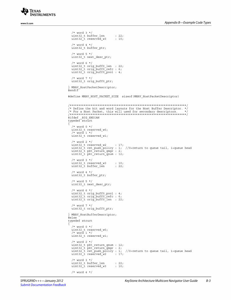
SPRUGR9D+++—January 2012 KeyStone Architecture Multicore Navigator User Guide B-3Submit Documentation Feedback
Appendix B—Example Code Typeswww.ti.com
/* word 3 */ uint32_t buffer_len : 22; uint32_t reserved_w3 : 10;
/* word 4 */ uint32_t buffer_ptr;
/* word 5 */ uint32_t next_desc_ptr;
/* word 6 */ uint32_t orig_buff0_len : 22; uint32_t orig_buff0_refc : 6; uint32_t orig_buff0_pool : 4;
/* word 7 */ uint32_t orig_buff0_ptr;
} MNAV_HostPacketDescriptor;#endif
#define MNAV_HOST_PACKET_SIZE sizeof(MNAV_HostPacketDescriptor)
/*******************************************************************//* Define the bit and word layouts for the Host Buffer Descriptor. *//* For a Host Packet, this will used for secondary descriptors. *//*******************************************************************/#ifdef _BIG_ENDIANtypedef struct{ /* word 0 */ uint32_t reserved_w0; /* word 1 */ uint32_t reserved_w1;
/* word 2 */ uint32_t reserved_w2 : 17; uint32_t ret_push_policy : 1; //0=return to queue tail, 1=queue head uint32_t pkt_return_qmgr : 2; uint32_t pkt_return_qnum : 12;
/* word 3 */ uint32_t reserved_w3 : 10; uint32_t buffer_len : 22;
/* word 4 */ uint32_t buffer_ptr;
/* word 5 */ uint32_t next_desc_ptr;
/* word 6 */ uint32_t orig_buff0_pool : 4; uint32_t orig_buff0_refc : 6; uint32_t orig_buff0_len : 22;
/* word 7 */ uint32_t orig_buff0_ptr;
} MNAV_HostBufferDescriptor;#elsetypedef struct{ /* word 0 */ uint32_t reserved_w0; /* word 1 */ uint32_t reserved_w1;
/* word 2 */ uint32_t pkt_return_qnum : 12; uint32_t pkt_return_qmgr : 2; uint32_t ret_push_policy : 1; //0=return to queue tail, 1=queue head uint32_t reserved_w2 : 17;
/* word 3 */ uint32_t buffer_len : 22; uint32_t reserved_w3 : 10;
/* word 4 */

B-4 KeyStone Architecture Multicore Navigator User Guide SPRUGR9D+++—January 2012Submit Documentation Feedback
Appendix B—Example Code Types www.ti.com
uint32_t buffer_ptr;
/* word 5 */ uint32_t next_desc_ptr;
/* word 6 */ uint32_t orig_buff0_len : 22; uint32_t orig_buff0_refc : 6; uint32_t orig_buff0_pool : 4;
/* word 7 */ uint32_t orig_buff0_ptr;
} MNAV_HostBufferDescriptor;#endif
// Host Buffer packet size is always the same as Host Packet size
/*********************************************************************//* Define the bit and word layouts for the Monolithic Pkt Descriptor.*//*********************************************************************/#ifdef _BIG_ENDIANtypedef struct{ /* word 0 */ uint32_t type_id : 2; //always 0x2 (Monolithic Packet ID) uint32_t packet_type : 5; uint32_t data_offset : 9; uint32_t packet_length : 16; //in bytes (65535 max)
/* word 1 */ uint32_t src_tag_hi : 8; uint32_t src_tag_lo : 8; uint32_t dest_tag_hi : 8; uint32_t dest_tag_lo : 8;
/* word 2 */ uint32_t epib : 1; //1=extended packet info block is present uint32_t reserved_w2 : 1; uint32_t psv_word_count : 6; //number of 32-bit PS data words uint32_t err_flags : 4; uint32_t ps_flags : 4; uint32_t reserved_w2b : 1; uint32_t ret_push_policy : 1; //0=return to queue tail, 1=queue head uint32_t pkt_return_qmgr : 2; uint32_t pkt_return_qnum : 12;
} MNAV_MonolithicPacketDescriptor;#elsetypedef struct{ /* word 0 */ uint32_t packet_length : 16; //in bytes (65535 max) uint32_t data_offset : 9; uint32_t packet_type : 5; uint32_t type_id : 2; //always 0x2 (Monolithic Packet ID)
/* word 1 */ uint32_t dest_tag_lo : 8; uint32_t dest_tag_hi : 8; uint32_t src_tag_lo : 8; uint32_t src_tag_hi : 8;
/* word 2 */ uint32_t pkt_return_qnum : 12; uint32_t pkt_return_qmgr : 2; uint32_t ret_push_policy : 1; //0=return to queue tail, 1=queue head uint32_t reserved_w2b : 1; uint32_t ps_flags : 4; uint32_t err_flags : 4; uint32_t psv_word_count : 6; //number of 32-bit PS data words uint32_t reserved_w2 : 1; uint32_t epib : 1; //1=extended packet info block is present
} MNAV_MonolithicPacketDescriptor;#endif
#define MNAV_MONO_PACKET_SIZE sizeof(MNAV_MonolithicPacketDescriptor)

SPRUGR9D+++—January 2012 KeyStone Architecture Multicore Navigator User Guide B-5Submit Documentation Feedback
Appendix B—Example Code Typeswww.ti.com
/*********************************************************************//* Define the word layout of the Extended Packet Info Block. It *//* is optional and may follow Host Packet and Monolithic descriptors.*//*********************************************************************/typedef struct{ /* word 0 */ uint32_t timestamp;
/* word 1 */ uint32_t sw_info0;
/* word 2 */ uint32_t sw_info1;
/* word 3 */ uint32_t sw_info2;
} MNAV_ExtendedPacketInfoBlock;

B-6 KeyStone Architecture Multicore Navigator User Guide SPRUGR9D+++—January 2012Submit Documentation Feedback
Appendix B—Example Code Types www.ti.com

SPRUGR9D+++—January 2012 KeyStone Architecture Multicore Navigator User Guide C-1Submit Documentation Feedback
Appendix C
Example Code Addresses
These #defines are the values referenced by the programming examples in this document. A register’s address is the combination of base_address + region_offset + register_offset + (instance_offset), where instance_offset is the copy of the desired register times the offset from one instance to the next (see ‘‘Example Code Utility Functions’’ on page A-1 for example of this).

C.1 KeyStone 1 Addresses:
C-2 KeyStone Architecture Multicore Navigator User Guide SPRUGR9D+++—January 2012Submit Documentation Feedback
Appendix C—Example Code Addresses www.ti.com
C.1 KeyStone 1 Addresses:#define QMSS_CFG_BASE (0x02a00000u)#define QMSS_VBUSM_BASE (0x34000000u)#define SRIO_CFG_BASE (0x02900000u)#define PASS_CFG_BASE (0x02000000u)#define FFTCA_CFG_BASE (0x021f0000u)#define FFTCB_CFG_BASE (0x021f4000u)#define AIF_CFG_BASE (0x01f00000u)
/* Define QMSS Register block regions. */#define QM_CTRL_REGION (QMSS_CFG_BASE + 0x00068000u)#define QM_DESC_REGION (QMSS_CFG_BASE + 0x0006a000u)#define QM_QMAN_REGION (QMSS_CFG_BASE + 0x00020000u)#define QM_QMAN_VBUSM_REGION (QMSS_VBUSM_BASE + 0x00020000u)#define QM_PEEK_REGION (QMSS_CFG_BASE + 0x00000000u)#define QM_LRAM_REGION ( + 0x00080000u)#define QM_INTD_REGION (QMSS_CFG_BASE + 0x000a0000u)#define QM_PROXY_REGION (QMSS_CFG_BASE + 0x00040000u)#define PDSP1_CMD_REGION (QMSS_CFG_BASE + 0x000b8000u)#define PDSP2_CMD_REGION (QMSS_CFG_BASE + 0x000bc000u)#define PDSP1_REG_REGION (QMSS_CFG_BASE + 0x0006E000u)#define PDSP2_REG_REGION (QMSS_CFG_BASE + 0x0006F000u)#define PDSP1_IRAM_REGION (QMSS_CFG_BASE + 0x00060000u)#define PDSP2_IRAM_REGION (QMSS_CFG_BASE + 0x00061000u)
/* Define QMSS PKTDMA Register block regions. */#define QMSS_PKTDMA_GBL_CFG_REGION (QMSS_CFG_BASE + 0x0006c000u)#define QMSS_PKTDMA_TX_CHAN_REGION (QMSS_CFG_BASE + 0x0006c400u)#define QMSS_PKTDMA_RX_CHAN_REGION (QMSS_CFG_BASE + 0x0006c800u)#define QMSS_PKTDMA_TX_SCHD_REGION (QMSS_CFG_BASE + 0x0006cc00u)#define QMSS_PKTDMA_RX_FLOW_REGION (QMSS_CFG_BASE + 0x0006d000u)
/* Define PASS PKTDMA Register block regions. */#define PASS_PKTDMA_GBL_CFG_REGION (PASS_CFG_BASE + 0x00004000u)#define PASS_PKTDMA_TX_CHAN_REGION (PASS_CFG_BASE + 0x00004400u)#define PASS_PKTDMA_RX_CHAN_REGION (PASS_CFG_BASE + 0x00004800u)#define PASS_PKTDMA_TX_SCHD_REGION (PASS_CFG_BASE + 0x00004c00u)#define PASS_PKTDMA_RX_FLOW_REGION (PASS_CFG_BASE + 0x00005000u)
/* Define SRIO PKTDMA Register block regions. */#define SRIO_PKTDMA_GBL_CFG_REGION (SRIO_CFG_BASE + 0x00001000u)#define SRIO_PKTDMA_TX_CHAN_REGION (SRIO_CFG_BASE + 0x00001400u)#define SRIO_PKTDMA_RX_CHAN_REGION (SRIO_CFG_BASE + 0x00001800u)#define SRIO_PKTDMA_TX_SCHD_REGION (SRIO_CFG_BASE + 0x00001c00u)#define SRIO_PKTDMA_RX_FLOW_REGION (SRIO_CFG_BASE + 0x00002000u)
/* Define FFTC A PKTDMA Register block regions. */#define FFTCA_PKTDMA_GBL_CFG_REGION (FFTCA_CFG_BASE + 0x00000200u)#define FFTCA_PKTDMA_TX_CHAN_REGION (FFTCA_CFG_BASE + 0x00000400u)#define FFTCA_PKTDMA_RX_CHAN_REGION (FFTCA_CFG_BASE + 0x00000500u)#define FFTCA_PKTDMA_TX_SCHD_REGION (FFTCA_CFG_BASE + 0x00000300u)#define FFTCA_PKTDMA_RX_FLOW_REGION (FFTCA_CFG_BASE + 0x00000600u)
/* Define FFTC B PKTDMA Register block regions. */#define FFTCB_PKTDMA_GBL_CFG_REGION (FFTCB_CFG_BASE + 0x00000200u)#define FFTCB_PKTDMA_TX_CHAN_REGION (FFTCB_CFG_BASE + 0x00000400u)#define FFTCB_PKTDMA_RX_CHAN_REGION (FFTCB_CFG_BASE + 0x00000500u)#define FFTCB_PKTDMA_TX_SCHD_REGION (FFTCB_CFG_BASE + 0x00000300u)#define FFTCB_PKTDMA_RX_FLOW_REGION (FFTCB_CFG_BASE + 0x00000600u)
/* Define AIF PKTDMA Register block regions. */#define AIF_PKTDMA_GBL_CFG_REGION (AIF_CFG_BASE + 0x00014000u)#define AIF_PKTDMA_TX_CHAN_REGION (AIF_CFG_BASE + 0x00016000u)#define AIF_PKTDMA_RX_CHAN_REGION (AIF_CFG_BASE + 0x00018000u)//#define AIF_PKTDMA_TX_SCHD_REGION (AIF_CFG_BASE + 0x00000000u)#define AIF_PKTDMA_RX_FLOW_REGION (AIF_CFG_BASE + 0x0001a000u)
/********************************************************************** * Define offsets to individual QM registers within an address region. *//* Queue Manager Region */#define QM_REG_QUE_REVISION 0x000#define QM_REG_QUE_DIVERSION 0x008#define QM_REG_STARVATION_CNT 0x020#define QM_REG_LINKRAM_0_BASE 0x00c#define QM_REG_LINKRAM_0_SIZE 0x010#define QM_REG_LINKRAM_1_BASE 0x014
/* Descriptor Memory Region */

C.1 KeyStone 1 Addresses:
SPRUGR9D+++—January 2012 KeyStone Architecture Multicore Navigator User Guide C-3Submit Documentation Feedback
Appendix C—Example Code Addresseswww.ti.com
#define QM_REG_MEM_REGION_BASE 0x000#define QM_REG_MEM_REGION_INDEX 0x004#define QM_REG_MEM_REGION_SETUP 0x008
/* Queue Management Region */#define QM_REG_QUE_REG_A 0x000#define QM_REG_QUE_REG_B 0x004#define QM_REG_QUE_REG_C 0x008#define QM_REG_QUE_REG_D 0x00c
/* Queue Status Region */#define QM_REG_QUE_STATUS_REG_A 0x000#define QM_REG_QUE_STATUS_REG_B 0x004#define QM_REG_QUE_STATUS_REG_C 0x008#define QM_REG_QUE_STATUS_REG_D 0x00c
/* Interrupt Distributor (INTD) Region */#define QM_REG_INTD_REVISION 0x000#define QM_REG_INTD_EOI 0x010#define QM_REG_INTD_STATUS 0x200#define QM_REG_INTD_STATUS_CLEAR 0x280#define QM_REG_INTD_INT_COUNT 0x300
/* PDSP(n) Reg Region */#define QM_REG_PDSP_CONTROL 0x000#define QM_REG_PDSP_STATUS 0x004#define QM_REG_PDSP_CYCLE_COUNT 0x00c#define QM_REG_PDSP_STALL_COUNT 0x010
/********************************************************************** * Define offsets to individual PKTDMA registers within an address region. *//* Global Cfg Register Block */#define PKTDMA_REG_REVISION 0x000#define PKTDMA_REG_PERFORMANCE_CTRL 0x004#define PKTDMA_REG_EMULATION_CTRL 0x008#define PKTDMA_REG_PRIORITY_CTRL 0x00c#define PKTDMA_REG_QM0_BASE_ADDR 0x010#define PKTDMA_REG_QM1_BASE_ADDR 0x014#define PKTDMA_REG_QM2_BASE_ADDR 0x018#define PKTDMA_REG_QM3_BASE_ADDR 0x01c
/* Tx Chan Cfg Register Block */#define PKTDMA_REG_TX_CHAN_CFG_A 0x000#define PKTDMA_REG_TX_CHAN_CFG_B 0x004
/* Rx Chan Cfg Register Block */#define PKTDMA_REG_RX_CHAN_CFG_A 0x000
/* Rx Flow Cfg Register Block */#define PKTDMA_REG_RX_FLOW_CFG_A 0x000#define PKTDMA_REG_RX_FLOW_CFG_B 0x004#define PKTDMA_REG_RX_FLOW_CFG_C 0x008#define PKTDMA_REG_RX_FLOW_CFG_D 0x00c#define PKTDMA_REG_RX_FLOW_CFG_E 0x010#define PKTDMA_REG_RX_FLOW_CFG_F 0x014#define PKTDMA_REG_RX_FLOW_CFG_G 0x018#define PKTDMA_REG_RX_FLOW_CFG_H 0x01c
/* Tx Sched Cfg Register Block */#define PKTDMA_REG_TX_SCHED_CHAN_CFG 0x000
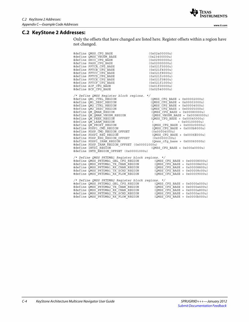
C.2 KeyStone 2 Addresses:
C-4 KeyStone Architecture Multicore Navigator User Guide SPRUGR9D+++—January 2012Submit Documentation Feedback
Appendix C—Example Code Addresses www.ti.com
C.2 KeyStone 2 Addresses:Only the offsets that have changed are listed here. Register offsets within a region have not changed.
#define QMSS_CFG_BASE (0x02a00000u)#define QMSS_VBUSM_BASE (0x23400000u)#define SRIO_CFG_BASE (0x02900000u)#define PASS_CFG_BASE (0x02000000u)#define FFTCA_CFG_BASE (0x021f0000u)#define FFTCB_CFG_BASE (0x021f4000u)#define FFTCC_CFG_BASE (0x021f8000u)#define FFTCD_CFG_BASE (0x021fc000u)#define FFTCE_CFG_BASE (0x021f0800u)#define FFTCF_CFG_BASE (0x021f1000u)#define AIF_CFG_BASE (0x01f00000u)#define BCP_CFG_BASE (0x02540000u)
/* Define QMSS Register block regions. */#define QM1_CTRL_REGION (QMSS_CFG_BASE + 0x00002000u)#define QM1_DESC_REGION (QMSS_CFG_BASE + 0x00003000u)#define QM2_CTRL_REGION (QMSS_CFG_BASE + 0x00004000u)#define QM2_DESC_REGION (QMSS_CFG_BASE + 0x00005000u)#define QM_QMAN_REGION (QMSS_CFG_BASE + 0x00080000u)#define QM_QMAN_VBUSM_REGION (QMSS_VBUSM_BASE + 0x00080000u)#define QM_PEEK_REGION (QMSS_CFG_BASE + 0x00040000u)#define QM_LRAM_REGION ( + 0x00100000u)#define QM_PROXY_REGION (QMSS_CFG_BASE + 0x000c0000u)#define PDSP1_CMD_REGION (QMSS_CFG_BASE + 0x000b8000u)#define PDSP_CMD_REGION_OFFSET (0x00004000u)#define PDSP1_REG_REGION (QMSS_CFG_BASE + 0x0006E000u)#define PDSP_REG_REGION_OFFSET (0x00000100u)#define PDSP1_IRAM_REGION (Qmss_cfg_base + 0x00060000u)#define PDSP_IRAM_REGION_OFFSET (0x00001000u)#define INTD1_REGION (QMSS_CFG_BASE + 0x000a0000u)#define INTD_REGION_OFFSET (0x00001000u)
/* Define QMSS PKTDMA1 Register block regions. */#define QMSS_PKTDMA1_GBL_CFG_REGION (QMSS_CFG_BASE + 0x00008000u)#define QMSS_PKTDMA1_TX_CHAN_REGION (QMSS_CFG_BASE + 0x00008400u)#define QMSS_PKTDMA1_RX_CHAN_REGION (QMSS_CFG_BASE + 0x00008800u)#define QMSS_PKTDMA1_TX_SCHD_REGION (QMSS_CFG_BASE + 0x00008c00u)#define QMSS_PKTDMA1_RX_FLOW_REGION (QMSS_CFG_BASE + 0x00009000u)
/* Define QMSS PKTDMA2 Register block regions. */#define QMSS_PKTDMA2_GBL_CFG_REGION (QMSS_CFG_BASE + 0x0000a000u)#define QMSS_PKTDMA2_TX_CHAN_REGION (QMSS_CFG_BASE + 0x0000a400u)#define QMSS_PKTDMA2_RX_CHAN_REGION (QMSS_CFG_BASE + 0x0000a800u)#define QMSS_PKTDMA2_TX_SCHD_REGION (QMSS_CFG_BASE + 0x0000ac00u)#define QMSS_PKTDMA2_RX_FLOW_REGION (QMSS_CFG_BASE + 0x0000b000u)