multichannel neutral atom energy spectrometers for plasma diagnostics
TRANSCRIPT
IEEE TRANSACTIONS ON PLASMA SCIENCE, VOL. PS-7, NO. 2, JUNE 1979
ACKNOWLEDGMENT
The authors wish to thank C. Boyd and J. Hong for design-ing and maintaining the data acquisition system used to recordthe ion acoustic wave data.
REFERENCES
[1] D. E. Smith, E. J. Powers, and G. S. Caldwell, "Fast-Fouriertransform spectral analysis techniques as a plasma fluctuationdiagnostic tool," IEEE Trans. Plasma Sci., vol. PS-2, p. 263,1974.
[2] D. E. Smith and E. J. Powers, "Experimental determination ofthe spectral index of a turbulent plasma from digitally computedpower spectra,"Phys. Fluids, vol. 16, p. 1373, 1973.
[3] W. C. Turner, E. J. Powers, and T. C. Simonen, "Properties ofelectrostatic ion-cyclotron waves in a mirror machine," Phys.Rev. Lett., vol. 39, p. 1087, 1977.
[4] E. J. Powers, "Spectral techniques for experimental determina-tion of plasma diffusion due to polychromatic fluctuations,"Nucl. Fusion, vol. 14, p. 749, 1974.
[5] J. R. Roth, W. M. Krawczonek, E. J. Powers, J. Y. Hong, andY. C. Kim, "Inward transport of a toroidally confined plasmasubject to strong radial electric fields," Phys. Rev. Lett., vol. 40,p. 1450, 1978.
[61 K. Hasselmann, W. H. Munk, and G. J. F. MacDonald, "Bi-spectra of ocean waves," in Time Series Analysis. M. Rosenblatt,Ed. New York: Wiley, 1963, p. 125.
[7] K. S. Lii, M. Rosenblatt, and C. VanAtta, "Bispectral measure-ments in turbulence," J. Fluid Mech., vol. 77, p. 45, 1976.
[8] Y. C. Kim and E. J. Powers, "Digital bispectral analysis of self-excited fluctuation spectra," Phys. Fluids, vol. 21, p. 1452, 1978.
[9] D. R. Brillinger and M. Rosenblatt, "Asymptotic theory of esti-mate of k-th order spectra," in Spectral Analysis of Time Series.B. Harris, Ed. New York: Wiley, 1967.
[10] , "Computation and interpretation of k-th order spectra," inSpectral Analysis of Time Series. B. Harris, Ed. New York:Wiley, 1967.
[11] A. S. Monin and A. M. Yaglom, Statistical Fluid Mechanics, vol.1. Cambridge, MA: MIT Press, 1971.
[12] D. R. Brillinger, Time Series. New York: Holt, 1975.[13] R. C. Davidson, Methods in Nonlinear Plasma Theory. New
York: Academic, 1972, ch. 6.[14] R. Z. Sagdeev and A. A. Galeev, Nonlinear Plasma Theory. New
York: Benjamin, 1969, ch. 1.[15] G. M. Jenkins and D. G. Watts, Spectral Analysis and Its Applica-
tion. San Francisco, CA: Holden-Day, 1968.[16] Y. C. Kim and E. J. Powers, "Effects of frequency averaging on
estimates of plasma wave coherence spectra," IEEE Trans. PlasmaSci., vol. PS-5, p. 31, 1977.
[17] E. 0. Brigham, The Fast Fourier Transform. Englewood Cliffs,NJ: Prentice-Hall, 1974.
[18] W. B. Davenport, Probability and Random Process. New York:McGraw-Hill, 1970, ch. 8.
[19] F. J. Harris, "On the use of windows for harmonic analysis withthe discrete Fourier transform," Proc. IEEE, vol. 66, p. 51, 1978.
[20] M. J. Hinich and C. S. Clay, "The application of the discreteFourier transform in the estimation of power spectra, coherence,and bispectra of geophysical data," Rev. Geophys., vol. 6, p. 347,1968.
[21] P. B. Mumola and E. J. Powers, "Characteristics of unstable wavesin a weakly ionized high-frequency magnetoplasma," Phys. Rev.Lett., vol. 22, p. 991, 1969.
[22] L. P. Mix, L. N. Litzenberger, and G. Bekefi, "Nonlinear couplingof ion-acoustic waves in a collisionless plasma," Phys. Fluids, vol.p. 2020, 1972.
[231 J. M. Buzzi and J. L. Hirshfield, "Nonlinear harmonic generationof ion-acoustic waves with dispersion," Phys. Fluids, vol. 19, p.554, 1976.
[24] B. B. Kadomtsev, Plasma Turbulence. New York: Academic,1965, p. 81.
Multichannel Neutral Atom Energy Spectrometersfor Plasma Diagnostics
S. H. ROBERTSON, M. GREENSPAN, P. KORN, MEMBER, IEEE, AND F. SANDEL
Abstract-Multichannel neutral atom energy spectrometers for energiesof 0.3-10 keV for use on fast pulsed plasma experiments are described.The spectrometers consist of a gas stripping cell, a fixed or variablemagnetic prism, and a row of scintillator-photomultiplier detectors.Calibration, data analysis, and some operating experience are described.
Manuscript received April 10, 1978; revised January 18, 1979. Thisresearch was sponsored by the U.S. Atomic Energy Commission and theAir Force Office of Scientific Research.
S. H. Robertson is with the Department of Physics, University of Cali-
INTRODUCTION
KNOWLEDGE of the ion distribution function is necessaryfor the calculation of fusion energy yields as well as the
diagnosis of ion heating schemes and velocity space dependentinstabilities. The determination of the energy spectrum ofneutral atoms created by charge exchange, though an indirectmethod of measuring the ion energy spectrum, is often theonly technique applicable to certain plasma experiments, and
fornia, Irvine, CA 92717. several devices for this purpose have been described in theM. Greenspan is with Laboratory of Plasma Studies, Cornell Univer- literature [1]-[5].
sity, Ithaca, NY 14850.P. Korn is with Maxwell Laboratories, Inc., San Diego, CA 92123. Barnett and Ray [5] have recently described a calibratedF. Sandel is with Naval Research Laboratory, Washington, DC 20375. single-channel neutral atom spectrometer in which detection
0018-9480/79/0600-0131$00.75 O 1979 IEEE
131
IEEE TRANSACTIONS ON PLASMA SCIENCE, VOL. PS-7, NO. 2, JUNE 1979
-
r00
l) Q
4 '
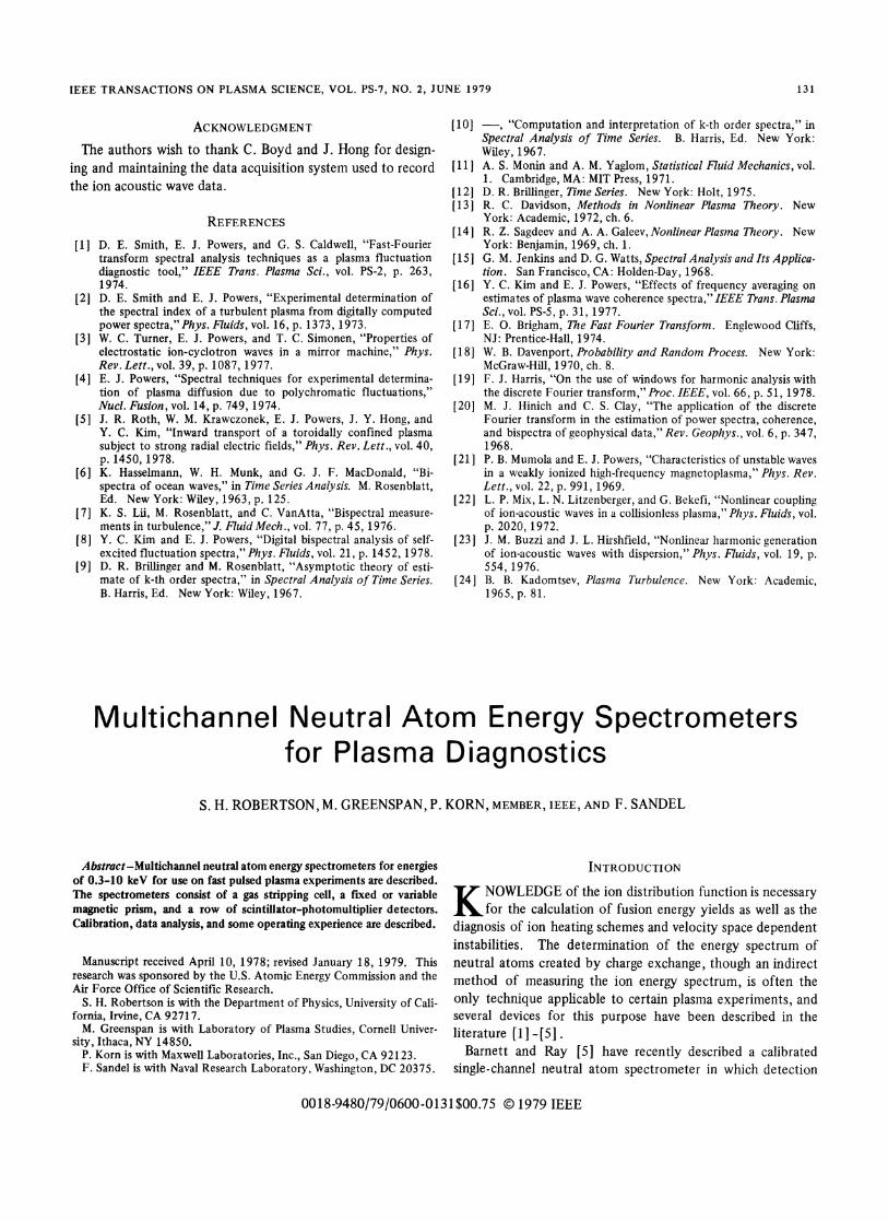
5 cmFig. 1. Vertical profile (above) and horizontal profile (below) of Device
I showing 0 gas cell, (E magnet, () ground plane, ® high-voltageplane, and ® photomultiplier and scintillator.
/X \
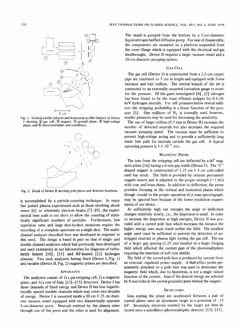
Fig. 2. Detail of Device II showing pole pieces and detector locations.
is accomplished by a particle-counting technique. In manyfast pulsed plasma experiments such as those involving shockwaves [6] or relativistic electron beams [7] -[9] , the experi-mental time scale is too short to allow the counting of statis-tically significant numbers of particles. Furthermore, low
repetition rates and large shot-to-shot variations require the
recording of a complete spectrum on a single shot. The multi-channel analyzer described here was developed in response tothis need. The design is based in part on that of single- anddouble-channel analyzers which had previously been developedand used extensively in our laboratories for diagnosis of turbu-lently heated [10], [11] and RF-heated [12] hydrogenplasmas. Two such analyzers having fixed (Device I, Fig. 1)and variable (Device II, Fig. 2) magnetic prisms are described.
APPARATUSThe analyzers consist of 1) a gas stripping cell, 2) a magnetic
prism, and 3) a row of Daly [13] -[15] detectors. Device I hasthree channels of fixed energy and Device II has four logarith-mically spaced tunable channels which may cover two decadesof energy. Device I is mounted inside a 30 cm X 25 cm diam-eter vacuum vessel equipped with two diametrically opposite5-cm-diameter ports. Neutrals emitted by the plasma enterthrough one of the ports and the other is used for alignment.
The vessel is pumped from the bottom by a 5-cm-diameterliquid-nitrogen baffled diffusion pump. For ease of disassembly,the components are mounted on a platform suspended fromthe cover flange which is equipped with the electrical and gasfeedthroughs. Device II requires a larger vacuum vessel and a10-cm-diameter pumping system.
GAS CELLThe gas cell (Device I) is constructed from a 2.5-cm copper
pipe tee machined to 5 cm in length and equipped with 3-mmentrance and exit orifices. The central branch of the tee isconnected to an externally mounted ionization gauge to moni-tor the pressure. Of the gases investigated [4], [5] nitrogenhas been found to be the most efficient stripper for 0.3-10-keV hydrogen neutrals. For cell pressures below several milli-torr the stripping probability is a linear function of the pres-sure [5]. One millitorr of N2 is normally used, however,smaller pressures may be used for decreasing the sensitivity.The use of larger orifices (9.5 mm in Device II) increases the
number of detected neutrals but also increases the requiredvacuum pumping speed. The vacuum must be sufficient toprevent high-voltage arcing and to provide a sufficiently longmean free path for neutrals outside the gas cell. A typicaloperating pressure is 3 X 10⁻⁵ torr.
MAGNETIC PRISMThe ions from the stripping cell are deflected by a 600 mag-
netic prism [16] having a 6-mm gap width (Device I). The "C"shaped magnet is constructed of 1.25 cm X 5 cm cold-rolledsteel bar stock. The field is provided by ceramic permanentmagnet inserts and is adjusted to the proper strength ('-1 kG)with iron and brass shims. In addition to deflection, the prismprovides focusing in the vertical and horizontal planes whichthough crucial to the proper operation of a mass spectrograph,may be ignored here because of the lower resolution require-ments of our device.At sufficiently high ion energies the angle of deflection
changes relatively slowly, i.e., the dispersion is small. In orderto increase the dispersion at high energies, Device II was pro-vided with a curved pole face which increases the distance thehigher energy ions must travel within the field. The smallestangle used must be sufficient to prevent the detection of un-stripped neutrals or plasma light exiting the gas cell. The useof a larger gap spacing (1.25 cm) resulted in a larger fringingfield which affected the current gain of the photomultipliersrequiring the insertion of soft iron shields.The field of the curved pole face is produced by current from
an external, regulated power supply. A Hall-effect probe per-manently attached to a pole face was used to determine themagnetic field which, due to hysteresis, is not a single valuedfunction of the current. Ions of the desired energy are selectedby 8-mm holes in the curved grounded plate behind the magnet.
DETECTORS
Ions exiting the prism are accelerated between a pair ofcurved plates onto an aluminum target at a potential of -15kV. Secondary electrons emitted by the target are then di-rected onto a scintillator-photomultiplier detector [ 1 3 ] - [1 51 .
132
6
ROBERTSON: et al.: MULTICHANNEL NEUTRAL ATOM ENERGY SPECTROMETERS
The aluminum targets are supported by 1.25-cm copper pipetees pressed into the back of the second curved plate. A gridimmediately behind the orifice in the second plate insures thatthe secondary electrons are accelerated toward the scintillator.The curved plates are cut from brass or aluminum tubing of6.3- and 7.5-cm radii and are mounted with their centers ofcurvature at the imaginary approximate point of intersectionof the ion trajectories near the center of the pole faces.The scintillators are 125-gm Pilot Bl plastic film cemented
to 21-mm-diameter glass disks and coated with -100 nm ofaluminum by vacuum deposition. The disks are supported inwells in an aluminum plate mounted above the targets. Theplate, scintillators, and tube shields are held at photocathodepotential.The photomultipliers are type 77672 which are 19 mm in
diameter. The tubes are fastened mechanically against theglass disks and the dynode resistors are oriented to permitclose spacing of the tubes. The detectors are sensitive to bothplasma light and X-rays and thus blackened light baffles, leadshielding, and low-profile thin scintillators are essential inmost experimental environments. In addition, some plasmaexperiments may produce a sufficiently large external magneticfield to require enclosure of the entire analyzer in magneticshielding.
CALIBRATIONThe positions of the detectors in Device II were chosen to
provide detection at hydrogen neutral energies of 1, 2, 4, and8 keV at a field strength of 1 kG. These positions and the poleface shapes were determined by ray tracing assuming that theions follow simple curves inside the virtual pole faces andstraight lines outside. The effect of the fringing field wasapproximated by assuming a virtual pole boundary 0.62 gapwidths beyond the physical boundary [16]. The channelswere found to be within 10 percent of the desired energies ata field of 1.1 kG. Device I has its lowest energy channel lo-cated to receive ions deflected 600 and the higher energychannels are located 2.5 cm between centers.The sensitivities of the channels are measured by recording
the photomultiplier currents as a function of the energy andintensity of a monoenergetic neutral hydrogen beam [4], [5].The beam intensity is measured with an electrometer and asecondary emission type Faraday cup having a sensitive area of1 cm2 and mounted on a movable arm directly in front of thegas cell. In order to cancel the effect of photoelectric currentsin the Faraday cup, each calibration point was determinedfrom the linear part of a graph of the anode current as a func-tion of the Faraday cup current. The neutral beam was createdby separating the H+ (or D+) component from the beam of aduoplasmatron or RF-type ion source with a 450 magneticprism and then neutralizing part of the beam in an 02 gas cell[4], [5]. A less expensive filament-type source [17] may beadequate because of the low beam intensities (10-10_10-7A/cm2 ) required to provide a measurable electrometer signal.The normalized sensitivities of the three channels of Device I
I Nuclear Enterprises, Inc., San Carlos, CA.2 Radio Corporation of America, Harrison, NJ.
100
5
2
10l
2!.
zrnc(L)
CL)(1)
x 5
2
-210
1 2 3°-0\/A tZls\
.2 .5 1 2 5 10keV
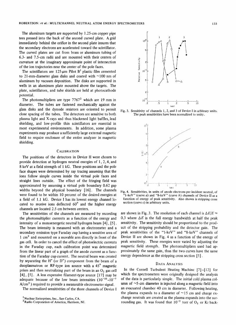
Fig. 3. Sensitivity of channels 1, 2, and 3 of Device I in arbitrary units.The peak sensitivities have been normalized to unity.
105 -
5 -
2A
5
2
a
10o __
2 5 1 2 5 10kev
Fig. 4. Sensitivities, in units of anode electrons per incident neutral, of"1-keV" (curve a) and "8-keV" (curve b) channels of Device II as afunction of energy of peak sensitivity. Also shown is stripping crosssection (curve c) in arbitrary units.
are shown in Fig. 3. The resolution of each channel is AE/E t
0.3 where /\E is the full energy bandwidth at half the peaksensitivity. The sensitivity should be proportional to the prod-uct of the stripping probability and the detector gain. Thepeak sensitivities of the "1-keV" and "8-keV" channels ofDevice II are shown in Fig. 4 as a function of the energy ofpeak sensitivity. These energies were varied by adjusting themagnetic field strength. The photomultipliers used had ap-proximately the same gain, thus the two curves have the sameenergy dependence as the stripping cross section [5] .
DATA ANALYSISIn the Cornell Turbulent Heating Machine [7] -[12] for
which the spectrometers were originally designed the analysisof the data is particularly simple. The initial cold plasma col-umn of -5-cm diameter is injected along a magnetic field intoan evacuated chamber 40 cm in diameter. Following heating,the plasma expands to a diameter of - 15 cm and charge ex-change neutrals are created as the plasma expands into the sur-rounding gas. It was found that 1 0-5 torr of 02 or Kr back-
133
4>410_
0l
3

IEEE TRANSACTIONS ON PLASMA SCIENCE, VOL. PS-7, NO. 2, JUNE 1979
(a) 925eV
(b) 1900eV
(c) 3700eV
(d) 7900eV
Time (2 Asec/div)
Fig. 5. Typical data obtained with Device II.
ground gas was sufficient to create a neutral flux in excess ofthat from other sources such as charge exchange on high-Z im-purity ions or from the dissociation of molecular ions. Thusthe ion distribution function, assuming isotropy, is given bythe simple relation [10]
f(E) (X I(E)a(E) S(E)E2(AE/E)
where I is the anode current of the channel of energy E, u(E)is the charge exchange cross section of the known backgroundgas, and S(E) is the analyzer sensitivity.For devices in which the plasma does not expand into a
known gas or is in contact with a wall, a complicated unfoldingprocess must be used in which multiple charge exchange colli-sions are included and allowances are made for radial tempera-ture variation and the attenuation of neutrals by electron im-pact ionization [18]. Furthermore, it has been shown thatfinite ion Larmor radius effects [11] , [12] can enhance thenumber of neutrals at high energy. Thus the spectrometersare more useful for comparative than absolute measurements.Typical data obtained with Device II are shown in Fig. 5.
The burst of neutrals created by the sudden expansion of theplasma column arrives at a time following the heating pulsewhich is given by the time of flight of H atoms at the appro-priate energy. The limited time resolution is given by thespread in time of flight determined from (AE/E). The timesof flight of impurities are, by their mass ratio, greater thanthat of hydrogen and serve to separate the signals as well as toallow their identification. The more massive atoms of a givenmomentum have the smaller energy and thus a set of grids be-tween the magnet and the first orifices may be used to bias outthe impurity signal if the temporal spacing is not sufficient forunambiguous measurements.Device I was used for the diagnosis of a high beta, shock
heated plasma in a coaxial electromagnetic shock tube [6].The neutrals were created in a 3 cm X 7 mm diameter tube
protruding many ion Larmor radii into the plasma. Chargeexchange occurred on the partially dissociated hydrogen fillinggas inside the tube which was not ionized by the incidentshock. The tube was differentially pumped to allow a freepath to the spectrometer.
In the latter experiment involving a dense plasma, the timefor the formation of a Maxwellian distribution was short com-pared to the plasma lifetime and thus three channels were con-sidered sufficient for the determination of the ion temperature.However, this was not the case in the Cornell Turbulent Heat-ing Machine and the four variable channels of Device II werenecessary for the examination of the non-Maxwellian distribu-tion resulting from the nonlinear heating mechanism employed.
ACKNOWLEDGMENTThe authors wish to thank Prof. H. H. Fleischmann, Prof. C.
B. Wharton, and Dr. D. S. Prono for many helpful discussions.They also wish to thank J. Osarczuk for fabrication of muchof the apparatus.
REFERENCES
[1] V. V. Afrosimov, I. P. Gladkovskii, Yu. S. Gordeev, I. F. Kalinke-vich, and N. V. Fedorenko, Sop. Phys.-Tech. Phys. (Englishtransl.), vol. 5, p. 1378, 1961.
[2] C. F. Barnett, J. L. Dunlap, R. S. Edwards, G. R. Haste, J. A. Ray,R. G. Reinhardt, W. J. Schill, R. M. Warner, and E. R. Wells,Nucl. Fusion., vol. 1, p. 264, 1961.
[31 H. P. Dubank and T. D. Wilkerson, Rev. Sci. Instrum., vol. 34,p. 12, 1963.
[41 H. H. Fleischmann and R. G. Tuckfield, Jr., Nucl. Fusion, vol. 8,p. 81, 1968.
[51 C. F. Barnett and J. A. Ray, Nucl. Fusion, vol. 12, p. 65, 1972.[6] S. Robertson and Y. G. Chen,Phys. Fluids,vol. 18, p. 917, 1975.[71 P. Korn, F. Sandel, and C. B. Wharton, Phys. Rev. Lett., vol. 31,
p. 579, 1973.[8] J. Appl. Phys., vol. 44, p. 4946, 1973.[9] IEEE Trans. Plasma Sci., vol. PS-3, p. 46, 1974.
[10] D. S. Prono and C. B. Wharton, Plasma Phys., vol. 15, p. 253,1973.
[11] S. H. Robertson, P. Korn, and C. B. Wharton, IEEE Trans. PlasmaSci., vol. PS-2, p. 17, 1973.
[12] D. G. Swanson, R. W. Clark, P. Korn, S. Robertson, and C. B.Wharton, Phys. Rev. Lett., vol. 28, p. 1015, 1972, and Phys.Fluids, vol. 17, p. 1322, 1974.
[13] W. Shutze and F. Bernhard, Z. Physik, vol. 145, p. 44, 1956.[14] N. R. Daly,Rev. Sci. Instrum.,vol. 31,pp. 264 and 720, 1960.[15] H. M. Gibbs and D. Commins, Rev. Sci. Instrum., vol. 3 7, p. 13 85,
1966.[16] H. A. Enge, in Focusing of Charged Particles, Albert Septier, Ed.
New York: Academic, 1967.[17] C. E. Anderson, in Methods of Experimental Physics, vol. 4,
L. Marton, Ed. New York: Academic, 1967.[18] 0. V. Konstantinov and V. I. Perel, Sov. Phys. -Tech. Phys. (En-
glish transl.), vol. 5, p. 1403, 1961.[19] H. H. Fleischmann and R. A. Young, Phys. Lett., vol. 29, p. 287,
1969.[20] P. M. Stier and C. F. Barnett,Phys. Rev., vol. 103, p. 896, 1956.
134
0cC),
co
8u(LI
a,0
2
z
4