multibody contact simula- tion of constant velocity ...€¦ · multibody contact simula-tion of...
TRANSCRIPT
IMW - Institutsmitteilung Nr. 35 (2010) 95
Multibody Contact Simula-tion of Constant Velocity Plunging Joint
Shen, L.J.
Constant velocity plunging joint is one of the important components in automotive drivelines, the overall dynamic performanc-es of the constant velocity plunging joint are not fully reported or described in the past. Intend to obtain more precise estimation of the dynamic contact forces between balls and races and the movements of the balls in races, this paper apply polygon contact model to simulate the contact dynamics of constant velocity plunging joint with SIMPACK software package.
1 Introduction
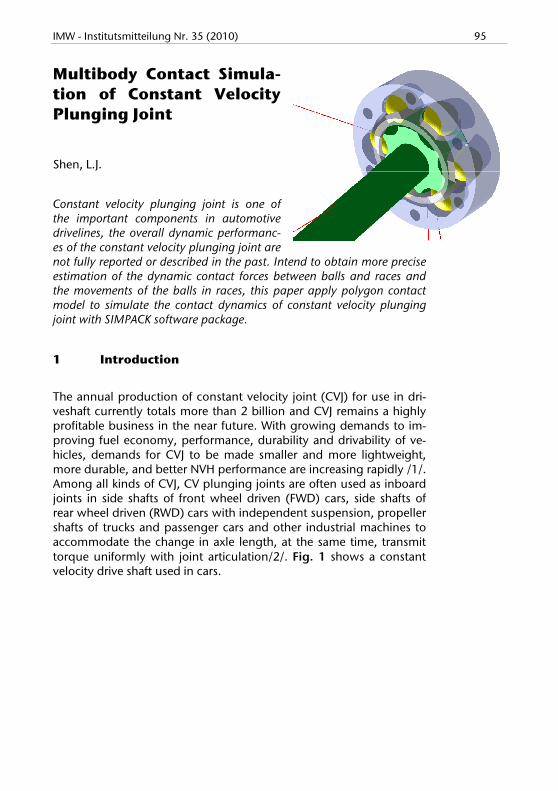
The annual production of constant velocity joint (CVJ) for use in dri-veshaft currently totals more than 2 billion and CVJ remains a highly profitable business in the near future. With growing demands to im-proving fuel economy, performance, durability and drivability of ve-hicles, demands for CVJ to be made smaller and more lightweight, more durable, and better NVH performance are increasing rapidly /1/. Among all kinds of CVJ, CV plunging joints are often used as inboard joints in side shafts of front wheel driven (FWD) cars, side shafts of rear wheel driven (RWD) cars with independent suspension, propeller shafts of trucks and passenger cars and other industrial machines to accommodate the change in axle length, at the same time, transmit torque uniformly with joint articulation/2/. Fig. 1 shows a constant velocity drive shaft used in cars.

96 IMW - Institutsmitteilung Nr. 35 (2010)
Figure1: Constant velocity drive shaft (after /1/)
The friction between balls and races leads to high plunging forces with increasing articulation of the joint. Therefore, deteriorate NVH performance of torque transmission /3/. Because of friction, the oscil-lating movement of the ball is not true rolling but consists of rolling, boring and sliding. Boring and sliding aggravate ball-track friction and then accelerate the process of fatigue. Carsten Bauer investigated the fatigue, internal friction and stress of CV plunging joint via analy-sis as well as experiments, he paid much attention to deal with the in-fluence of induction annealing to the internal stress and non-destructive test of the fatigue quantitatively /4/. So, understanding the dynamic contact of ball-races and movement of balls will help us find ways to decrease boring and sliding, therefore, improve the fati-gue life, NVH performance/5/. This paper will apply polygon contact model (PCM) to simulate the multi-body contact dynamics of CV plunging joint with SIMPACK software package, and investigate the movement of the balls under running state.
2 Multibody contact model of the CV plunging joint
All components of CV plunging joint are assembled by mechanical contacts, leads to a multibody contact system /6/. Contacts between all the components of CV plunging joint are shown in Fig. 2. In the entire joint, there are 24 helical surface-to-sphere contacts (ball-race contact), 12 sphere-to-plane contacts (ball-cage window contact), 12 sphere-to-cylindrical contacts (ball-cage window contact), and 1

IMW - Institutsmitteilung Nr. 35 (2010) 97
sphere-to -cylindrical contact (cage-outer race contact) and 1 sphere-to-sphere contact (cage-inner race contact).
Figure 2: Contacts between components of CV plunging joint
Because the races of CV plunging joint are helical surface, which makes most of the common contact models are not applicable in this case. And just because of this, there’s few publications mentioned the multi-body contact dynamic simulation of CV plunging joint up to now, though a number of multi-body contact dynamic simulations are done in CV fixed joint. Recently, Gerhard Hippmann presented a compliant contact algorithm named Polygonal Contact Model (PCM) to deal with contact between complexity shaped surfaces in multi-body dynamics/7-8/. In PCM, the body surfaces are represented by polygon meshes, two polygonal surfaces collide if at least one pair of intersecting polygons exists, and contact force determination by the elastic foundation model and regularized Coulomb’s friction. This model facilitated multi-body contact dynamic simulation of CV plunging joint. To relieve the difficulty of calculation and conver-gence, the inner race-cage contact and the outer race-cage contact are replaced by user defined joints ( ; , ,X
). Other contacts are
modeled with PCM.
When a car run in the road, the wheel and wheel plate move up and down, resulting the plunging of the intermediate shaft (see Fig. 1), so the wheel shaft and wheel plate are also included in the multibody model, the constant velocity fixed joint is modeled as a “constant ve-

98 IMW - Institutsmitteilung Nr. 35 (2010)
locity joint” in Simpack. The screenshot of the whole multibody mod-el is shown in Fig. 3.
Figure3: Screenshot of the multibody model of CV plunging joint
3 Multibody contact simulation and simulation results
Tab. 1 shows the main dimensions of ball plunging CVJ and load conditions used in the simulation. The driving torque loaded on the outer race of CV plunging joint and the resisting torque loaded on the wheel shaft are 1000 N·m and -1000 N·m respectively. The initial angle velocity of the joint is 80 Rad/s.
Ball diame-ter d
Effective ra-dius R
Torque T Velocity ω
22.225 mm 31.95 mm 1000 Nm 80 Rad/s
Table 1: Main dimensions and load conditions used in the simulation
At first, the CV plunging joint is running with fixed articulation angle 100, that’s to say, without plunging. Fig. 4 shows the change of con-tact forces between balls and races during rotation of the joint. The

IMW - Institutsmitteilung Nr. 35 (2010) 99
changes of contact forces are consistent with the analytical results without considering the ball-race friction in reference /4/. Saw-toothed curves in Fig. 4 is due to coarse discrete of the contact sur-face and ball-race friction in multibody simulation, finer contact sur-face mesh will improve the continuity of the curve but more calcula-tion time. Fig. 5 shows the change of ball centre position, velocity as well as angle velocity of ball1 relative to inner race1 and outer race1 during rotation of the joint.
Figure 4: Change of contact force between balls and races during rotation of the joint (with
fixed articulation angle 100)
Figure 5: Movement of ball 1 relative to inner and outer races under fixed articulation angle

100 IMW - Institutsmitteilung Nr. 35 (2010)
When the joint is plunging between 50 and 150 (with preliminary ar-ticulated angle 100), the position of ball centre, velocity and angle ve-locity of ball1 relative to inner races and outer races are shown in Fig. 6. When the joint enter stable running state, the curve of position, ve-locity and angle velocity are similar to sinusoid, though there’s more or less deviation. It can be read qualitatively from phase difference be-tween velocity and angle velocity that the motion of balls is not pure rolling
4 Conclusion
The multibody contact simulation of constant velocity plunging joint is carried out in Simpack software package using the so named po-lygonal contact model (PCM). The change of ball-race contact forces, ball centre position, velocity as well as angle velocity of balls relative to inner races and outer races in running states are calculated. They are consistent with the analytical results before. Further studies will analyze the kinestate of balls relative to races in contact points.
Figure 6: Movement of ball 1 relative to inner and outer race in plunging

IMW - Institutsmitteilung Nr. 35 (2010) 101
5 References
/1/ http://www.gkndriveline.com/
/2/ Schmelz, F., Seherr-Thoss, H. Aucktor, E.: Universal Joints and Driveshafts. Springer, Berlin, 2006.
/3/ Baron, E. NVH phenomena in constant-velocity joints - a 3-fold approach. In Engineering for the customer - FISITA 1992: Au-tomotive technology serving society. 1992.
/4/ Carsten Bauer. Untersuchungen zu Beanspruchung, Ferti-gungstechnik, tribologi -schem Verhalten und Verschleißen-prüftechnik von Kulgel-Gleichlauf-verschiebe -gelenken. Stutt-gart, 1988.
/5/ Tawil, M. Lebensdauerprüfung von Gelenkwellen. IMW-Institutsmitteilung Nr.25, Clausthal 2000
/6/ Serveto, S.M., J-P; Diaby, M, Secondary torque in automotive drive shaft ball joints: influence of geometry and friction Proc. IMechE Part K: J. Multi-body Dynamics, 2008. 222(3): p. 215-227.
/7/ Hippmann, G., An Algorithm for Compliant Contact Between Complexly Shaped Bodies Multibody System Dynamics, 2004. 12(4): p. 345-362.
/8/ S. Ebrahimi, G.H., and P. Eberhard, EXTENSION OF THE POLYGONAL CONTACT MODEL FOR FLEXIBLE MULTIBODY SYSTEMS. Int. J. of Appl. Math. and Mech., 2005. 1: p. 33-50.