multi-service tactics, techniques, and … · this multi-service tactics, techniques, and...
TRANSCRIPT

i
UXO MULTI-SERVICE TACTICS,
TECHNIQUES, AND PROCEDURES FOR
UNEXPLODED EXPLOSIVE ORDNANCE OPERATIONS
FM 3-100.38 MCRP 3-17.2B NTTP 3-02.4.1
AFTTP(I) 3-2.12
AUGUST 2005
DIS T RIBU T I ON R E S T RIC T I O N : Approved for public release; distribution is unlimited.
FOREWORD This publication has been prepared under our direction for use by our respective commands
and other commands as appropriate.
DAVID A. FASTABEND Brigadier General, US Army Deputy Director/Chief of Staff Futures Center
US Army Training and doctrine Command
JOHN M. KELLY
THOMAS L. CONANT Brigadier General, USMC Director Expeditionary Force Development Center
BENTLEY B. RAYBURN Rear Admiral, USN Major General, USAF Commander Commander Navy Warfare Development Headquarters Air Force
Command Doctrine Center
This publication is available through the ALSA Web site (www.alsa.mil); through the Army at Army
Knowledge Online (AKO) (www.us.army.mil) and at the General Dennis J. Reimer Training and Doctrine Digital Library (www.train.army.mil) Web sites; and
through the Air Force at the Air Force Publishing Web site (www.e-publishing.af.mil).

_____________________________
PREFACE
1. Purpose This multi-Service tactics, techniques, and procedures (MTTP) publication provides
commanders and their units guidelines and strategies for operating with unexploded explosive ordnance (UXO) hazards, while minimizing the impact of these hazards on friendly operations. This publication will facilitate coordination, integration, and force protection requirements regarding UXO during joint exercises, contingencies, or other operations. It also identifies functions and responsibilities for planning, reporting, tracking, and clearing UXO, while minimizing the impact of UXO on the mission.
2. Scope This MTTP publication describes the UXO threat and provides guidelines to minimize the
impact of UXO hazards. It provides warfighting personnel at the operational and tactical levels with information to optimize UXO safety and to increase efficiency, while reducing or eliminating losses of personnel and equipment to UXO hazards.
3. Applicability This publication applies to all commanders, leaders, staff, and warfighters participating in
joint operations. It will assist the joint force commander (JFC), Service component commanders, their staffs, and anyone responsible for force protection of personnel and resources.
4. Implementation Plan Participating Service command offices of primary responsibility will review this publication,
validate the information, and reference and incorporate it in Service and command manuals, regulations, and curricula as follows:
Army. Upon approval and authentication, this publication incorporates the procedures contained herein into the United States (US) Army Doctrine and Training Literature Program as directed by the Commander, US Army Training and Doctrine Command (TRADOC). Distribution is in accordance with applicable directives and the Initial Distribution Number (IDN) listed on the authentication page.
Marine Corps. The Marine Corps will incorporate the procedures in this publication in US Marine Corps training and doctrine publications as directed by the Commanding General, US Marine Corps Combat Development Command (MCCDC). Distribution is in accordance with the Marine Corps Publication Distribution System (MCPDS).
Navy. The Navy will incorporate these procedures in US Navy training and doctrine publications as directed by the Commander, Navy Warfare Development Command (NWDC)[N5]. Distribution is in accordance with Military Standard Requisition and Issue Procedure Desk Guide (MILSTRIP Desk Guide) Navy Supplement Publication-409 (NAVSUP P409).
Air Force. The Air Force will incorporate the procedures in this publication in accordance with applicable governing directives. Distribution is in accordance with Air Force Instruction (AFI) 33-360.
Marine Corps PCN: 144 000105 00
16 August 2005 FM 3-100.38/MCRP 3-17.2B/NTTP 3-02.4.1/AFTTP(I) 3-2.12 i

5. User Information a. TRADOC, MCCDC, NWDC, Headquarters AFDC, and the Air Land Sea Application
(ALSA) Center developed this publication with the joint participation of the approving Service commands. ALSA will review and update this publication as necessary.
b. This publication reflects current joint and Service doctrine, command and control organizations, facilities, personnel, responsibilities, and procedures. Changes in Service protocol, appropriately reflected in joint and Service publications, will likewise be incorporated in future revisions to this document.
c. We encourage recommended changes for improving this publication. Recommended changes should reference a specific page and paragraph and provide a rationale for each recommendation. Send comments and recommendations directly to—
ATTN: AFTC-RD
iMarine Corps
ATTN:
l
ATTN: N5
E-mail: [email protected] Air Force
ATTN: DJ
ALSA
Army Commander, US Army Training and Doctrine Command
Fort Monroe VA 23651-5000 DSN 680-4489 COMM (757) 788-4489 E-mail: doctr [email protected]
Commanding General, US Marine Corps Combat Development Command C427
3300 Russell Road, Suite 318A Quantico VA 22134-5021 DSN 278-2871/6227 COMM (703) 784-2871/6227 E-mail: [email protected]
Navy Commander, Navy Warfare Development Command
686 Cushing Road Newport RI 02841-1207 DSN 948-1070/4201 COMM (401) 841-1070/4201
Commander, Air Force Doctrine Center
155 North Twining Street Maxwell AFB AL 36112-6112 DSN 493-2640/2256 COMM (334) 953-2640/2256 E-mail: [email protected]
Director, ALSA Center 114 Andrews Street Langley AFB VA 23665-2785 DSN 575-0902 COMM (757) 225-0902 E-mail: [email protected]
FM 3-100.38/MCRP 3-17.2B/NTTP 3-02.4.1/AFTTP(I) 3-2.12 16 August 2005 ii

*FM 3-100.38 MCRP 3-17.2B NTTP 3-02.4.1
AFTTP(I) 3-2.12
FM 3-100.38 US Army Training and Doctrine Command Fort Monroe, Virginia
MCRP 3-17.2B Marine Corps Combat Development Command Quantico, Virginia
NTTP 3-02.4.1 Navy Warfare Development Command Newport, Rhode Island
AFTTP(I) 3-2.12 Headquarters, Air Force Doctrine Center Maxwell Air Force Base, Alabama
16 August 2005
UXO MULTI-SERVICE TACTICS, TECHNIQUES AND PROCEDURES
FOR UNEXPLODED ORDNANCE OPERATIONS
TABLE OF CONTENTS
Page EXECUTIVE SUMMARY ............................................................................................ v
CHAPTER I UXO HAZARDS........................................................................ I-1Background......................................................................................... I-1Hazards .............................................................................................. I-2
CHAPTER II JOINT FORCE UXO OPERATIONS........................................ II-1Purpose ............................................................................................. II-1Operational Considerations ............................................................... II-1Responsibilities.................................................................................. II-2Capabilities ........................................................................................ II-4Identifying .......................................................................................... II-5Marking .............................................................................................. II-5Reporting ........................................................................................... II-5Tracking ............................................................................................. II-5
DISTRIBUTION RESTRICTION: Approved for public release; distribution is unlimited.
* This publication supersedes FM 3-100.38/MCRP 3-17.2B/NTTP 3-02.4.1/AFTTP(I) 3-2.12, 23 August 2001.
16 August 2005 FM 3-100.38/MCRP 3-17.2B/NTTP 3-02.4.1/AFTTP(I) 3-2.12 iii

CHAPTER III SERVICE COMPONENT CAPABILITIES .............................. III-1Background....................................................................................... III-1US Army ........................................................................................... III-1US Marine Corps .............................................................................. III-3US Navy............................................................................................ III-4US Air Force ..................................................................................... III-4
APPENDICES A. Identifying UXO ............................................................................ A-1B. Marking UXO................................................................................ B-1C. Reporting UXO.............................................................................C-1D. Protective Measures ....................................................................D-1E. UXO Graphics Symbols ............................................................... E-1F. Obstacle Numbering and Tracking ............................................... F-1G. UXO Training ...............................................................................G-1
REFERENCES .................................................................................References-1 GLOSSARY .....................................................................................Glossary-1 INDEX .......................................................................................... Index-1
FIGURES Figure B-1. Hazard Sign Shapes with Mine Symbol.......................... B-2Figure B-2. Other Explosive Hazard Symbols ................................... B-2Figure B-3. Hazard Sign Language ................................................... B-3Figure B-4. Minefield Fencing............................................................ B-5Figure D-1. Barricade Examples........................................................D-2Figure E-1. Graphic for a Point UXO ................................................. E-1Figure E-2. Graphic for a UXO Area.................................................. E-2Figure E-3. Mine and Minefield Graphics .......................................... E-3Figure E-4. UXO Overlay and Legend Example................................ E-4Figure F-1. Obstacle Number Scenario ............................................. F-2
TABLES Table C-1. Sample Explosive Hazard Spot Report............................C-2Table D-1. Evacuation Distances ......................................................D-1Table F-1. Obstacle Number Field Character Explanation ................ F-3Table F-2. Obstacle Types ................................................................ F-4
FM 3-100.38/MCRP 3-17.2B/NTTP 3-02.4.1/AFTTP(I) 3-2.12 16 August 2005 iv

EXECUTIVE SUMMARY
UXO
Multi-Service Tactics, Techniques, and Procedures for Unexploded Explosive Ordnance Operations
This MTTP publication—
• Describes the UXO threat to friendly forces and operations. • Provides guidelines for planning, reporting, tracking, and marking UXO hazards and
training recommendations for the joint force. • Provides commanders several options for applying force protection measures
against UXO hazards. • Delineates the roles of explosive ordnance disposal (EOD) and engineer units with
regard to UXO hazards. • Describes Service-specific UXO missions and capabilities.
Introduction Military operations produce UXO hazards. UXO pose a threat to mobility, personnel,
equipment, and facilities. Understanding the impact of UXO hazards and the procedures used to minimize their effects can maximize the efficiency of resources available during a joint operation. Establishing procedures and training the force to react to these hazards enhance joint force capabilities. This publication contains MTTP to mitigate UXO hazards while conducting joint operations.
Concept This publication makes a critical distinction between land-based mines and other UXO
hazards. Mines and minefields are, by definition, a category of UXO. Distinction of the specific type of UXO is critical to determine which methods and forces to employ to mitigate the hazards of mines and other UXO. Breaching, reducing, or clearing land-based mine hazards is primarily the responsibility of combat engineer units. Reducing or clearing of all other UXO hazards, which includes improvised explosive devices (IEDs), is primarily the responsibility of EOD units. (More details concerning this distinction are in chapter II.) Non-UXO-trained personnel should mark and report UXO hazards using the methods prescribed in this publication. It is critical that EOD personnel conduct clearance of UXO hazards. This publication is not intended to train Soldiers, Marines, Sailors, or Airmen as UXO experts.
Organization The chapters in this MTTP address UXO hazards, procedures for avoiding UXO hazards,
and a description of unique Service capabilities. The appendices of this MTTP are quick reference sources defining specific skills needed when UXO hazards are encountered.
16 August 2005 FM 3-100.38/MCRP 3-17.2B/NTTP 3-02.4.1/AFTTP(I) 3-2.12 v

Chapters Chapter I: Defines UXO hazards and describes the degree of risk for different operational
categories (such as maneuver, air assault, aviation, amphibious, and air base operations).
Chapter II: Describes the responsibilities for planning and executing a joint operation with UXO hazards. This chapter introduces the UXO reporting, marking, and tracking requirements and defines considerations for planning and conducting operations with UXO hazards. It also defines options commanders may use when confronting UXO hazards.
Chapter III: Outlines individual Service missions, command and control (C2) structures, and specific capabilities of engineer and EOD forces of each Service.
Appendices Appendix A: Assists non-UXO-trained personnel in identifying the different types of UXO
hazards. This appendix complements Appendix C by providing methods to describe and identify UXO hazards during reporting. Identification of the ordnance type is a requirement for line 4 of the explosive hazard spot report (SPOTREP).
Appendix B: Describes the procedures for marking UXO hazards to warn personnel operating in the proximity of the hazard and assists clearance personnel in finding the hazard.
Appendix C: Describes the routing and format of the 9-line Explosive Hazard SPOTREP.
Appendix D: Provides three methods to protect personnel and equipment when operating near UXO hazards: evacuate, isolate, or barricade. This appendix further describes the benefits of each method and provides examples to assist with implementation.
Appendix E: Describes graphic control measures to assist commanders, staff, and warfighters in tracking UXO hazards.
Appendix F: Describes the numbering methodology for tracking and labeling UXO and obstacles on the engineer obstacle overlay.
Appendix G: Provides leaders a guide for training military personnel on identifying, marking, and reporting UXO hazards. This appendix also describes the protective measures necessary for survival when operating in an environment containing UXO hazards.
FM 3-100.38/MCRP 3-17.2B/NTTP 3-02.4.1/AFTTP(I) 3-2.12 16 August 2005 vi
PROGRAM PARTICIPANTS The following commands and agencies participated in the development of this publication:
Joint Joint Staff, J-7, Joint Doctrine Education and Training Division, Washington, D.C. Joint Staff, J-34, Combating Terrorism, Washington, D.C. Department of Defense EOD Technology and Training Secretariat, Indian Head, MD Joint Warfighting Center, Fort Monroe, VA Commandant, Naval School EOD, Eglin AFB, FL
Army HQDA, ATTN: DALO-AMA-EOD, Washington, D.C. US Army Training and Doctrine Command, Futures Center, Joint and Allied Doctrine
Division (ATTN: ATFC-RD), Fort Monroe, VA US Army Engineer School, Doctrine Division, Fort Leonard Wood, MO XVIII Airborne Corps, Assistant Corps Engineer, Fort Bragg, NC HQ, 52nd Ordnance Group (EOD), Fort Gillem, GA HQ, 79th Ordnance Battalion (EOD), Fort Sam Houston, TX US Army Technical Detachment, Navy EOD Technology Division, Indian Head, MD Army EOD Training Representative, Fort Lee, VA
Marine Corps Marine Corps Combat Development Command, Joint Doctrine Branch (C427) and Ground
Branch (C422), Quantico, VA Marine Corps Detachment, Naval School Explosive Ordnance Disposal Marine Corps EOD
Center of Excellence, Eglin AFB, FL HQ, USMC Logistics, Planning, and Operations, Washington, D.C. Marine Corps Detachment, Navy EOD Technical Division, Indian Head, MD
Navy Navy Warfare Development Command, ALSA Liaison Officer (LNO), Norfolk Naval Base,
Norfolk, VA Commander, EOD Group ONE, San Diego, CA Commander, EOD Group TWO, Norfolk, VA
Air Force Air Force Civil Engineer Support Agency, Tyndall AFB, FL HQ, USAF Civil Engineer, Washington, DC HQ, Air Force Doctrine Center, Maxwell AFB, AL HQ, Air Combat Command, CE/EOD Division, Langley AFB, VA HQ, Air Force Special Operations Command, CE/EOD Division, Hurlburt Field, FL HQ, Air Force Materiel Command, CE/EOD Division, Wright-Patterson AFB, OH HQ, Air Force Space Command, CE/EOD Division, Peterson AFB, CO HQ, Air Mobility Command, CE/EOD Division, Scott AFB, MO
16 August 2005 FM 3-100.38/MCRP 3-17.2B/NTTP 3-02.4.1/AFTTP(I) 3-2.12 vii
HQ, Air Education Training Command, CE/EOD Division, Randolph AFB, TX HQ, United States Air Forces in Europe, CE/EOD Division, Ramstein AFB, Germany HQ, Pacific Air Forces, CE/EOD Division, Hickam AFB, HI 75th Civil Engineer Group, Hill AFB, UT 56th Civil Engineer Squadron, Luke AFB, AZ Detachment 63, Aircraft and Armament Center, Indian Head, MD
FM 3-100.38/MCRP 3-17.2B/NTTP 3-02.4.1/AFTTP(I) 3-2.12 16 August 2005 viii

Chapter I
UXO HAZARDS
1. Background a. Introduction. Saturation with unexploded explosive ordnance (UXO) has become a
characteristic of the modern battlespace and will likely continue to threaten military forces and operations. US personnel have been killed or injured by UXO in virtually every conflict or contingency in which the United States has participated. This can be attributed primarily to unfamiliarity with UXO countermeasures and avoidance procedures. Every individual participating in a joint operation should be able to recognize and react safely to UXO hazards. To this end, leaders should train their personnel to conduct operations in UXO contaminated environments. Commanders should further consider risks to personnel and operations from UXO and integrate the impact of the UXO hazard into mission planning. This multi-Service tactics, techniques, and procedures (MTTP) publication provides the appropriate information for planning, implementing, and executing operations to minimize risks to forces and operations from UXO. Examples illustrated in this publication are US ordnance; however, most foreign militaries possess explosive ordnance with similar capabilities and hazards.
b. Minefields and UXO Differentiation. The joint term for UXO includes mines and minefields; however, there are basic differences in how a joint force manages mines and other UXO hazards. This MTTP publication will differentiate between mine hazards and all other UXO in specific circumstances. This distinction guides the commander’s determination of which methods and forces to employ to mitigate the hazards based on the situation. Breaching, reducing, or clearing land-based mine hazards is the responsibility primarily of Army and Marine Corps combat engineer units. Refer to Joint Publication (JP) 3-15, Joint Doctrine for Barriers, Obstacles, and Mine Warfare, for joint breaching and mine clearance guidance.
c. Improvised Explosive Device (IED) and UXO Differentiation. UXO may be used as a component in an improvised explosive device (IED) However, IEDs should not be classified as UXOs. MTTP for UXO differs greatly from that of an IED. IED defeat actions are the responsibility of all personnel and activities that are involved in the identification, deterrence, avoidance, and mitigation of the effects of IED threats. However, the render safe portion of IED neutralization actions is the exclusive responsibility of explosive ordnance disposal (EOD) units. Refer to specific Service doctrine and policy as well as operational specific plans and rules of engagement for IED related planning and execution guidance.
d. Captured Enemy Ammunition (CEA). CEA is discovered or captured quantities of stored, cached, or abandoned enemy ammunition and explosives. Recovery and evacuation of CEA are command responsibilities at all echelons. CEA may be encountered during all phases of military operations and is commonly found during raid and patrol operations. Caches of CEA may be as small as one or two pieces of ordnance or as large as several thousand pieces of ordnance. Caches can be found in schools, homes, mosques, hospitals, sewage systems or buried in farmers’ fields. Large quantities of CEA may also be found in Ammunition Storage Points (ASPs) similar to our ASPs. Basic CEA planning and execution factors are the same regardless of the amount of CEA encountered. Commanders and leaders at all levels must involve EOD and trained ammunition handling specialists in the planning of CEA operations and should utilize them (when available) in the execution of CEA operations.
16 August 2005 FM 3-100.38/MCRP 3-17.2B/NTTP 3-02.4.1/AFTTP(I) 3-2.12 I-1

2. Hazards a. Production of Hazards. The United States prides itself on the low dud rates of its
munitions; however, all explosive ordnance has the potential to become UXO. Therefore, commanders and staff should plan for dud munitions and their impact on future maneuver or cleanup after hostilities are complete. The actual hazard area produced by UXO depends on the type and density. The following examples provide a method to predict the potential magnitude of a UXO hazard:
(1) A fire mission of 36 Multiple Launch Rocket System rockets could produce 1,159 (36 X 644 X 5 percent dud rate) UXO hazards in the target area.
(2) A B-52 dropping a full load of 45 cluster bomb units (CBUs) (with each CBU containing up to 650 submunitions) may produce 1,462 (650 X 45 X 5 percent dud rate) UXO hazards.
(3) Scatterable mines can produce a significant amount of UXO hazards. For example, the bomb live unit-91 and 92/B Gator System can dispense hundreds of mines covering an average area of 200 by 650 meters in a matter of seconds. All scatterable mines have a self-destruct mechanism, ranging from 4 hours to 15 days; however, if the self-destruct mechanism fails they could become UXO hazards. Other US and foreign mines can be programmed to self-destruct up to 300 days from battlefield delivery.
b. Impact on Operations. UXO concerns all ground, air, and maritime forces because all forces operating in areas with UXO hazards are at risk. UXO affects operational and tactical planning and execution of operations. The presence of UXO in operational areas can add considerable time to any operation. Commanders and planners can minimize unnecessary delays by accurately planning for UXO hazards, while also having forces trained to respond correctly when these hazards are encountered. Without prior planning and coordination, maintaining the operational tempo is more difficult in a UXO environment.
c. Degree of Risk. Variables affecting the degree of risk include, but are not limited to:
(1) Types and density of explosive ordnance employed by enemy and friendly forces.
(2) Protection available to personnel, equipment, and facilities (such as armored vehicles versus dismounted infantry, revetted aircraft over exposed aircraft, or fortified positions over exposed positions).
(3) Mission and degree of mobility required of the affected force.
(4) Terrain and climatic conditions.
d. Impacts to Ground-based Mobility. UXO inhibits mobility by:
(1) Restricting the use of terrain, while reducing momentum (to include speed of maneuver and rates of march).
(2) Increasing reconnaissance requirements.
(3) Inhibiting night movement, while increasing risks.
(4) Increasing the risk to combat, combat support, and combat service support elements.
(5) Requiring the allocation of trained forces and other resources to clear and mark lanes.
(6) Reducing combat power due to potential losses of personnel and equipment.
FM 3-100.38/MCRP 3-17.2B/NTTP 3-02.4.1/AFTTP(I) 3-2.12 16 August 2005 I-2

e. Hazards to Armored Vehicles. Armored vehicles offer varying degrees of protection from UXO. Armored crews can reduce their risk from some but not all UXO hazard areas by remaining mounted. When conducting risk assessment, type and size of the potential UXO must be considered. Although some UXOs may disable the vehicles by breaking or throwing tracks others may result in catastrophic injury.
f. Hazards to Nonarmored Vehicles. Personnel in nonarmored vehicles face nearly the same risk from UXO as dismounted forces because the protection afforded by nonarmored vehicles is negligible. The nonarmored vehicles are also vulnerable to damage or destruction from UXO.
g. Hazards to Dismounted Forces. Dismounted forces face the greatest risk from UXO. To reduce this risk, dismounted forces need to be able to identify UXO hazards correctly, understand procedures for avoiding and reporting these hazards, and be aware of UXO hazard areas previously reported.
h. Hazards to Air Assault and Aviation Forces. Air assault and aviation forces are also at risk to UXO. Aircraft in defilade, flying nap-of-the-earth, or in ground effect (below 45 feet) are vulnerable to UXO. US and foreign munitions incorporate sensitive fusing that can react to aircraft in ground effect. Aviation units should be aware of hazard areas and conduct a thorough reconnaissance before occupying or conducting operations (to include occupying assembly areas and forward arming and refueling points).
i. Hazards to Air Base Operations. UXO contaminating aircraft launch, recovery, and support areas have the potential to affect expeditionary forces. UXOs have a negative effect on launch and recovery of aircraft. Most associate this effect with the impact on strike aircraft supporting joint operations. UXOs, however, can also influence the reception of combat forces and their movement to forward areas; movement of materiel, replacement personnel, and support forces; evacuation of patients, other casualties, and human remains; evacuation of US nationals and other noncombatants, or allied/coalition partners; evacuation of enemy prisoners of war, civilian internees, detainees, and refugees; and the retrograde of materiel. Mitigating these hazards before landing any forces and establishing operational areas requires adequate planning and allocation of necessary forces to accomplish the task.
j. Hazards to Amphibious Landing Craft. UXO has the potential to significantly damage certain types of landing craft and in some cases result in casualties of embarked personnel. Sea and anti-landing mines can also deny access to selected landing sites and sea-lanes. Mitigating these hazards before landing forces requires adequate planning and allocation of necessary forces to accomplish the task.
k. Hazards to Civilians and Civil Infrastructure. UXO poses a significant hazard to civilians and the infrastructure within the area of operations (AO) . Because most civilians are not familiar with military ordnance, they are largely unaware of the extreme hazard that UXO presents. Due to this unfamiliarity, civilians, often-curious children, will pick up and handle UXO items with devastating effects. Civilians have also been killed or injured by buried UXO while performing routine tasks, such as walking or digging. In an effort to reclaim homes and reestablish lives during post-conflict operations, local civilians have collected and returned hazardous UXO items to US forces. Unfortunately, UXOs will continue to be a deadly hazard to unwary indigenous personnel after cessation of military operations. Additionally, the effects of UXO on the civil population and infrastructure can create significant, and often very undesirable, diplomatic, economic, and information impacts.
16 August 2005 FM 3-100.38/MCRP 3-17.2B/NTTP 3-02.4.1/AFTTP(I) 3-2.12 I-3

This page intentionally left blank.

Chapter II
JOINT FORCE UXO OPERATIONS
1. Purpose Joint operations have become the routine method of employing US forces. This chapter
provides standardized methods for joint force command and control (C2); EOD and engineer employment; reporting, marking, and tracking UXO; and protective measures when operating in a UXO environment. It also defines the command, staff, and warfighting responsibilities employed to minimize UXO risks to the joint force.
2. Operational Considerations a. General. The threat of having UXOs used as a component of an IED can affect the
morale of the fighting force, restrict mobility, increase logistical burdens, divert resources from the primary mission, and produce casualties. Integrated planning, reporting, and tracking of UXO throughout the theater are critical to successful joint and multinational operations. The air tasking order, rules of engagement, and coordinating instructions in the operation plan (OPLAN) or operation order (OPORD) are tools to inform the force and reduce the impact of UXO on joint operations.
b. UXO Considerations. (1) Knowing the availability, prioritization, and task organization of limited theater EOD.
(2) Knowing the impact on current and future military operations (including the terrain; effect on timing; positioning of forces; routes for maneuver and logistics units; potential chemical, biological, radiological, and nuclear [CBRN] detection and decontamination support; and survivability requirements).
(3) Knowing UXO locations and densities (multinational and enemy).
(4) Increasing logistical requirements (e.g., demolition material).
(5) Knowing the method/process and communications capability to report, track, and disseminate UXO hazards.
(6) Designating recovery, disposal, and safe holding areas.
(7) Knowing security requirements.
(8) Knowing the impact on the civilian populace and infrastructure.
(9) Destroying UXO in a timely manner to preclude enemy use in IEDs.
(10) Training all personnel in UXO hazards.
c. CEA Considerations. (1) Planning for CEA security, logistics, reporting, tracking, safe holding areas, and
disposal operations.
16 August 2005 FM 3-100.38/MCRP 3-17.2B/NTTP 3-02.4.1/AFTTP(I) 3-2.12 II-1
(2) Ensuring qualified EOD personnel supervise the assessment and disposition of CEA in order to not contaminate the battle field with UXO. Improper disposal of CEA can produce catastrophic results for friendly forces and civilian population.
(3) Ensuring proper handling of CEA to prevent the ordnance from being used as an IED.
(4) Instructing subordinates that CEA could provide potential intelligence information describing new and/or modified weapons systems.
(5) Being aware of CEA hazards:
• Improper storage configuration
• Armed munitions
• Chemical and biological
• Potential booby-traps
d. Commander's Options. There is no single device or technique that will eliminate every UXO encountered. Clearance operations are inherently hazardous and consume time. After assessing the UXO hazards germane to the mission, several options are available to the commander:
Note: If UXOs are expected to be encountered, commanders should request EOD support during operations planning.
(1) Bypass the hazard, mark and report it.
(2) Employ tactical breaching procedures.
Note: Conventional minefield breaching methods, while effective in mitigating UXO threats to a maneuvering combat arms unit, will normally require follow-on UXO area and route clearance actions.
(3) Self-extract to alternate routes or positions.
(4) Restrict from use.
(5) Clear by priority area.
(6) Clear completely.
(7) Accept the risk of casualties and continue with the assigned mission.
3. Responsibilities Responsibilities for planning, directing, managing, and executing the joint UXO mission
extend from the combatant commander throughout the staff, to the subordinate JFC to the Service and functional command forces. Appendices A through G provide guidelines to assist the entire force with UXO identification and marking, reporting, protecting, tracking, and training.
a. Joint Force Commander (JFC). The JFC’s and supporting combatant commander’s guidance may address specific considerations for UXO hazards. The guidance may include priority of engineer and EOD support, management of joint fires, and C2 measures. The JFC's intent should provide safety guidance and establish procedures to reduce the potential for fratricide within the joint operations area (JOA). The JFC should also include EOD and engineer special staff officers in all operational planning to take full advantage of their ordnance and mine clearing/breaching expertise.
FM 3-100.38/MCRP 3-17.2B/NTTP 3-02.4.1/AFTTP(I) 3-2.12 16 August 2005 II-2

b. JFC Intelligence Staff Section (J-2). The J-2 is responsible for preparing and disseminating all known information on the enemy ordnance order of battle, weapon systems, activity that results in UXO hazard areas, minefields, and locations of ammunition supply points. This information must include known and suspected chemical, biological, radiological, nuclear, and high yield explosives (CBRNE) capabilities and their potential employment.
c. JFC Operations Staff Section (J-3). The J-3 plans and coordinates the commander's guidance and establishes procedures to inform the joint force of all UXO hazard areas. The J-3, in coordination with the joint force engineer and EOD staffs, establishes joint force reporting and tracking procedures.
d. JFC Plans Staff Section (J-5). The J-5 incorporates the commander's guidance regarding joint force UXO reporting and tracking procedures into OPLANs/OPORDs. The J-5 considers future terrain needs, while minimizing the impact of enemy and friendly-generated UXO. Additionally, the J-5 ensures plans and orders include adequate safety of personnel and procedures to reduce the potential for fratricide.
e. Joint Rear Area Coordinator (JRAC). The JRAC, if designated, plays a critical role in UXO reporting in the joint rear area (JRA) and must be part of the coordination and information network dealing with UXO. The JRAC is responsible for creating a secure environment in the JRA to facilitate sustainment, host nation support, infrastructure development, and joint force movements. The JRAC ensures that all personnel and units operating in the rear area follow JFC-established UXO hazard tracking, disseminating, and reporting procedures. The JRAC must also coordinate with the JFC staff, lead service (if designated), and/or joint task force (JTF) that has control of the EOD and engineer forces responsible for UXO operations in the JRA.
f. Joint Force Engineer. The joint force engineer is responsible for providing comprehensive recommendations to the JFC on the effective employment of combat engineering (mobility, countermobility and survivability), general engineering, and geospatial engineering capabilities in support of joint operations. The joint force engineer is the staff element responsible for planning, reporting, and tracking barriers, obstacles, and minefields. The staff also plans for the removal or deactivation of barriers, obstacles, and mines during or after hostilities or other operations. During operations, the joint force engineer receives, consolidates, and disseminates obstacle information to the staff and affected units. The joint force engineer staff also incorporates hazard area information onto the obstacle overlay. The obstacle overlay is the primary source depicting UXO hazard areas and provides mobility input into the common operational picture (COP). The engineer staff maintains all reports and historical data on obstacles and hazard areas for use during current and future operations.
Note: For further guidance on the joint force engineer, refer to JP 3-34, Engineer Doctrine for Joint Operations. For further guidance on barriers, obstacles, and minefield planning, refer to JP 3-15, Joint Doctrine for Barriers, Obstacles, and Mine Warfare.
g. Joint Force EOD Staff Officer. The joint force EOD officer is the staff element responsible for coordinating the detection, identification, recovery, evaluation, rendering safe, and final disposition of explosive ordnance. He/she is typically assigned to the J-3 staff section and augments the J-5 with planning issues relating to explosive ordnance. In addition to coordinating staff responsibilities, the EOD officer specifically:
(1) Establishes and operates an EOD-incident reporting system.
(2) Establishes, operates, and manages technical intelligence reporting procedures.
(3) Coordinates requirements for EOD support with Service components, multinational partners, and civilian organizations, as appropriate.
16 August 2005 FM 3-100.38/MCRP 3-17.2B/NTTP 3-02.4.1/AFTTP(I) 3-2.12 II-3
h. JFC Service Component Units. Service component responsibilities include UXO planning, identification, marking, reporting, and tracking UXO hazards within their assigned AO. See the appendix section for detailed information.
i. EOD Joint Task Force. It is possible to have a JTF that has EOD function as its sole mission. This type of JTF may be formed as a stand-alone or subordinate JTF controlling (via operational control [OPCON] or tactical control [TACON] of attached units) two or more Service component EOD organizations. If established, the EOD JTF commander would be responsible for making recommendations to the senior JFC (senior JTF commander, subunified command commander, or geographic combatant commander) on the proper employment of EOD and on how to accomplish assigned operational missions. See FM 4-30.16/MCRP 3-17.2C/NTTP 3-02.5/AFTTP(I) 3-2.32 Multiservice Procedures for Explosive Ordnance Disposal in a Joint Environment, for additional information on an EOD C2 option.
j. Joint EOD Operations Center (JEODOC). A JEODOC is a multifunctional operations center that may be established under the control of the JTF J-3. The primary purpose of the JEODOC is to manage theater-level UXO hazard-reduction operations and EOD planning, integrating, coordinating, and tasking function (through the direction and authority of the commander) when there is no subordinate EOD-focused JTF to accomplish this task. The JFC, with recommendations from the J-3, determines the need for the JEODOC whenever the EOD management requirements are beyond the capability of the J-3 or subordinate EOD force headquarters. See FM 4-30.16/MCRP 3-17.2C/NTTP 3-02.5/AFTTP(I) 3-2.32, Multiservice Procedures for Explosive Ordnance Disposal in a Joint Environment, for additional information on a JEODOC.
4. Capabilities a. EOD. Army, Marine Corps, Navy, and Air Force EOD units diagnose, render safe, and
dispose of UXO that threaten personnel, facilities, and operations throughout the JOA. Joint regulations and Department of Defense (DOD) directives prescribe specific responsibilities for each Service. (See chapter III for Service-specific roles and capabilities.) Common EOD training, equipment, and technical manuals provide each Service the capability to:
(1) Perform actions to locate and gain access to UXO.
(2) Conduct diagnostic actions to identify and evaluate UXO.
(3) Perform render safe procedures by applying special methods and tools.
(4) Direct actions to recover or perform final disposition of UXO.
(5) Perform technical intelligence collection and exploitation of first seen or previously unknown ordnance.
(6) Perform these procedures on US and foreign (conventional or CBRN) UXO and IEDs.
b. Army and Marine Corps Combat Engineers. (See chapter III for Service-specific roles and capabilities of engineers.) Land combat operations will most likely involve countering enemy barriers, obstacles, and minefields. Army and Marine Corps combat engineers provide combat engineering (mobility, countermobility, and survivability operations) in support of the joint force land component commander (JFLCC). Mobility operations make maneuver possible, regardless of enemy obstacle efforts. Since units can encounter obstacles when conducting any movement, joint forces integrate breaching operations into all movement plans. When possible, units bypass enemy obstacles to maintain momentum and conserve critical countermobility
FM 3-100.38/MCRP 3-17.2B/NTTP 3-02.4.1/AFTTP(I) 3-2.12 16 August 2005 II-4
assets. Navy construction engineers (SEABEEs) and Air Force civil engineers do not play a leading role in mobility (breaching and clearance) operations.
c. Non-UXO Trained Personnel. As previously discussed (chapter I, paragraph 1.b.), commanders may use non-EOD personnel, under direct EOD supervision, to reduce mobility obstacle related UXO hazards in exceptional circumstances. When non-EOD personnel perform limited UXO hazard removal and destruction, these non-EOD personnel require special training and direct supervision by qualified EOD personnel.
5. Identifying Proper identification of UXO when reporting assists EOD in understanding the hazard in
order to provide the commander with the best course of action to mitigate the threat. (See appendix A.)
6. Marking When UXO is encountered, it should be clearly marked using standard markers. These
standard markers warn other friendly personnel and noncombatants of the potential hazard (See appendix B for proper marking procedures.)
7. Reporting a. Introduction. Timely and accurate UXO reporting and intelligence information gathering
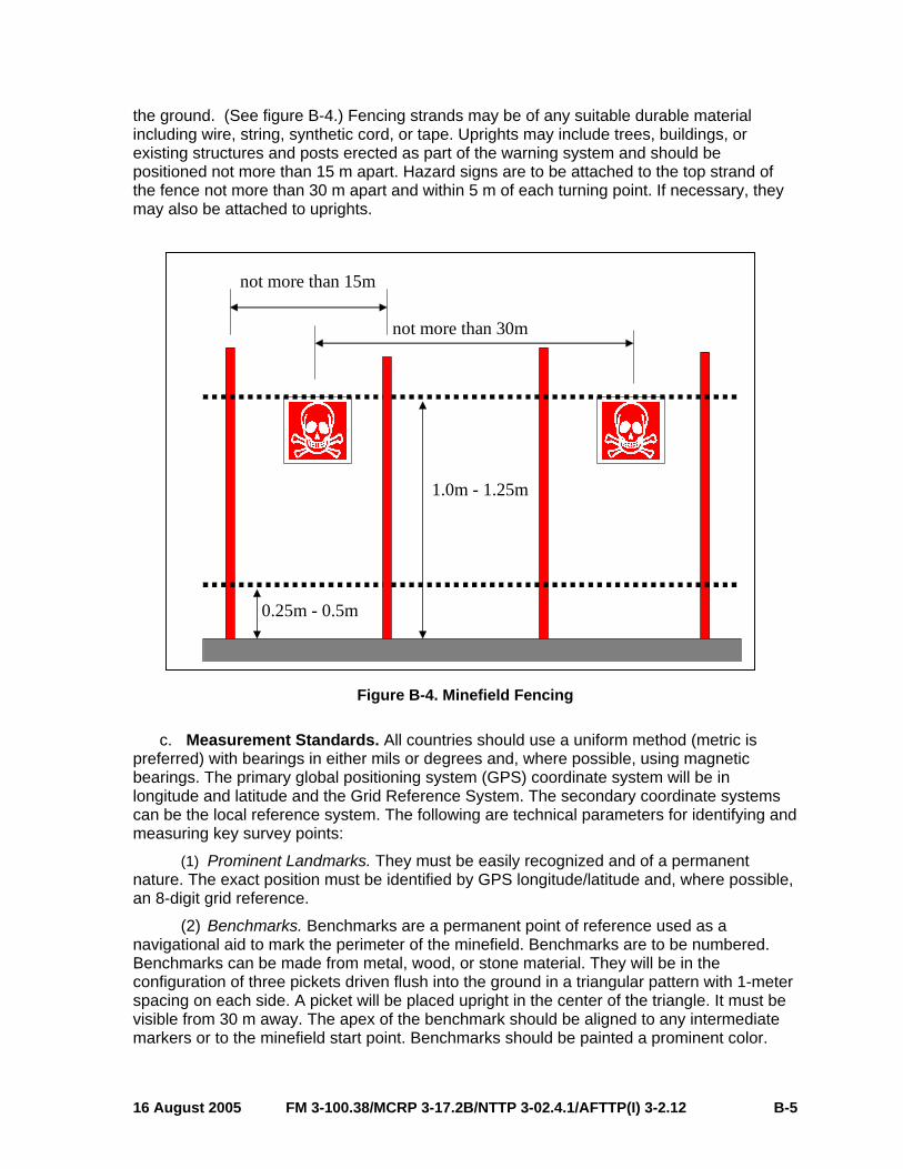
procedures are critical to the safe conduct of operations within the JOA. During joint operations, utilization of the standard explosive hazard (EH) SPOTREP will prevent redundancy and ensure accurate incident reporting, tasking, and tracking. Line 4 of the EH SPOTREP (see table C-1) requires the identification of the type of ordnance. Appendix A provides useful guidelines and information to describe the type of hazard correctly.
b. Dissemination. Timely dissemination of the EH SPOTREP allows joint forces to counter the hazards associated with UXO effectively. The J-3 receives the EH SPOTREP through the chain of command and forwards the report to the joint force engineer and the EOD operation center. The joint force engineer converts the EH SPOTREP onto the engineer obstacle overlay for dissemination to subordinate units. The joint force engineer then processes, plots, and disseminates the information to higher, lower, and adjacent units.
8. Tracking a. Tracking Methods. Appendices C, E, and F provide useful information to assist
commanders and staff with the UXO tracking process. Appendix C provides the format for reporting a UXO hazard; appendix E is a tool for plotting and tracking UXO hazards; and appendix F, Obstacle Numbering and Tracking, is useful for tracking all obstacles in the JOA. Every unit is responsible for the tracking of obstacles in their area of operations. Units obtain this information from individual SPOTREPs, EH 9-line SPOTREPs, intelligence reports, situational awareness, and the obstacle overlay.
b. Tracking Prioritization. Until each UXO hazard is cleared, the joint force engineer staff tracks all known obstacles (to include UXO hazards), with assistance from the joint force EOD staff officer. The joint force engineer tracks, on the obstacle overlay, all known obstacles that may operationally impact friendly forces. If excessive UXO is likely, the JFC may direct the engineer to prioritize the tracking effort. The JFC bases the tracking level on the location, amount, and threat of potential UXO hazards. In these cases, the EOD and engineer staff officers must prioritize tracking the hazards, presenting the greatest danger and those most
16 August 2005 FM 3-100.38/MCRP 3-17.2B/NTTP 3-02.4.1/AFTTP(I) 3-2.12 II-5
operationally significant to the force. The joint force EOD officer, in coordination with the joint force engineer, maintains records and other historical information on reported UXO hazard areas. This information is used by follow-on units and units conducting civil-military or post-conflict operations. Regardless of the density of the UXO hazard, the joint force engineer will always track all obstacles.
FM 3-100.38/MCRP 3-17.2B/NTTP 3-02.4.1/AFTTP(I) 3-2.12 16 August 2005 II-6
Chapter III
SERVICE COMPONENT CAPABILITIES
1. Background This chapter outlines individual Service EOD and engineer missions, C2 structures, and
operational planning considerations in support of UXO operations. This chapter implements the following standardization agreements (STANAGs):
a. STANAG 2079, Rear Area Security and Rear Area Damage Control.
b. STANAG 2143, Explosive Ordnance Reconnaissance/Explosive Ordnance Disposal.
c. STANAG 2377, Procedures for the Management of an EOD Incident for Use When Working With Other Agencies.
d. STANAG 2389, Minimum Standards of Proficiency for Trained Explosive Ordnance Disposal Personnel.
e. STANAG 2485, Engineer Countermine Operations.
f. STANAG 2834, The Operation of the EOD Technical Information Center.
g. STANAG 2929, Airfield Damage Repair.
h. STANAG 2957, International System Used by Armed Forces in the Nuclear Field.
2. US Army a. EOD.
(1) Mission. The US Army EOD mission is to support the JFC by providing the capability to neutralize hazards from conventional UXO and CBRNE hazards that present a threat to operations, installations, personnel and/or materiel. Army EOD forces can also dispose of hazardous foreign or US ammunition, UXO, individual mines, booby-trapped mines, and chemical mines. EOD provides the Army with a rapidly deployable support package for the elimination of hazards from UXO in any operational environment. The EOD force neutralizes UXO that is restricting freedom of movement and denying access to supplies, facilities, and other critical assets. Army EOD forces equip, train, and organize to support tactical land forces across the spectrum of operations.
(2) C2. The EOD group provides C2 for all Army EOD assets and operations in theater. When directed by the JFC, the EOD group may become the nucleus of a subordinate EOD-focused JTF. The EOD battalions provide C2, mission tasking, technical intelligence acquisition/management, and limited administrative and logistics support for up to 10 EOD companies. The EOD group, battalion, and company commanders have the additional duty of performing as the EOD special staff officer to their respective Service component or functional command. In the absence of a fully deployed EOD group, battalion, or battalion (-), the command element may deploy as the C2 element for Army EOD assets in a given operation. Refer to Army FM 4-30.12 (FM 9-15), Explosive Ordnance Disposal Service and Unit Operations, and FM 4-30.16/MCRP 3-17.2C/NTTP 3-02.5/AFTTP(I) 3-2.32, Multiservice
16 August 2005 FM 3-100.38/MCRP 3-17.2B/NTTP 3-02.4.1/AFTTP(I) 3-2.12 III-1

Procedures for Explosive Ordnance Disposal in a Joint Environment, for additional guidance on Army EOD operations.
(3) Operational Planning. The EOD group and EOD battalion provide staff planning for Army EOD operations throughout the Army Forces (ARFOR) AO, and in most operational situations in other land areas within the JOA as determined by the JFC. Thus, the EOD group commander has the additional duty of performing as the EOD special staff officer to the ARFOR commander. The EOD battalion commander would also serve as the EOD special staff officer at an Army-based JTF and, possibly, at the coalition JTF level. In the absence of a deployed EOD group or EOD battalion, the senior ranking Army EOD officer also serves as the ARFOR EOD staff officer. The Army EOD commander/staff officer is responsible for providing the EOD annex to all OPLANs/OPORDs. This ensures that EOD forces fully understand and support the ARFOR commander’s operations and also provides for force protection throughout the AO.
b. Army Engineers. (1) Mission. Army engineers provide a full range of engineering capabilities to the JFC.
The US Army maintains forces that have the capability to perform most combat (mobility, countermobility, and survivability), general, and geospatial operations within the engineer battlespace functions. Specific engineering missions concerning UXO are reconnaissance, detection, breaching, clearing, proofing, and marking of obstacles. In extreme high-operational tempo or high-intensity combat missions, US Army engineer or other non-EOD units may conduct limited reduction or clearing of UXO hazards. During stability and support operations engineers using explosive ordnance clearance agents (EOCA), through the technical guidance of Army EOD, will perform limited UXO clearance. Engineers may also assist EOD forces in battlefield UXO disposal and CEA reduction operations as required. JP 3-34 Engineer Doctrine for Joint Operations, and FM 3-34, Engineer Operations, provides more details on specific engineer units and tasks.
(2) C2. Command authority over engineer units is given to a maneuver commander when he/she needs responsive engineer support. The command relationship is OPCON or TACON. Supporting relationships include direct support or general support. Direct support authorization occurs when the maneuver commander requires immediate responsiveness from engineers, but does not need task organization authority. General support authorization occurs when the higher headquarters requires central control and flexibility when employing limited engineer assets. Army C2 units in theater include:
(a) Engineer command, a major subordinate command of the Army Service component command.
(b) Engineer brigade(s).
(c) Maneuver enhancement brigade(s).
(d) Engineer battalion(s).
(e) Combat engineer companies and platoons. The engineer platoon is the lowest level at which a combat engineer unit can effectively accomplish independent tasks. The maneuver commander gets optimum support when the engineer company or platoon is under the maneuver commander’s direct control.
Note. Refer to FM 3-34 (FM 5-100), Engineer Operations, for additional information on Army engineer C2.
(3) Operational Planning. The primary Army engineer elements that conduct mobility operations are combat engineers. Related combat engineer mission support modules include
FM 3-100.38/MCRP 3-17.2B/NTTP 3-02.4.1/AFTTP(I) 3-2.12 16 August 2005 III-2

sapper companies, mobility augmentation companies (with assault bridging, breaching, and countermobility capabilities), clearance companies (route and area clearance capabilities) and Explosive Hazards Coordination Cells. Each maneuver brigade combat team (BCT) has organically assigned combat engineers and is task organized with a supporting engineer expeditionary package, with one or more engineer companies providing augmentation based upon mission requirements. It is common to task organize additional combat engineer units to weight the main effort. Adjustment of the level of engineer support occurs after a thorough mission, enemy, terrain and weather, troops and support available, and time available (METT-T) analysis. (The Army adds a letter “C” to the end of the acronym for civil considerations [METTTC].) Additional engineer units not specifically assigned to the BCT may operate in the BCT area on a task basis.
(4) Explosive Ordnance Clearance Agents (EOCAs). Are trained combat engineers (21B) non-commissioned officers and officers who have a limited capability to dispose select UXOs (in place only) as identified in the EOCA Technical Manual or through EOD staff guidance in the AO. EOCAs are also used in combat breaching, route and area clearance operations.
3. US Marine Corps a. EOD. Marine Corps’ EOD basic mission is to support Marine operating forces, national
security strategy, and force protection, by locating, accessing, identifying, rendering safe, neutralizing, and disposing of hazards from foreign and domestic, conventional, CBRNE , UXO, IEDs, and weapons of mass destruction, that present a threat to operations, installations, personnel, or materiel.
Note: USMC EOD units are authorized to conduct field disassembly and inerting operations for the purpose of exploitation and intelligence gathering.
(1) C2. Command, control, and coordination of EOD assets falls under the EOD Control Center (EODCC). The EODCC is normally located within the Marine air-ground task force (MAGTF) operations section and staffed with an EOD Officer and Senior Enlisted EOD SNCO. The EOD Officer is a special staff officer to the MAGTF Commander. The MAGTF EOD Officer tracks all requests for EOD support, plans and prioritizes missions, and provides a liaison capability when conducting joint operations.
The EOD officer/team leader directs and coordinates the execution of EOD tasks in support of the commander’s intent. The EODCC ensures complete EOD support to all units. The senior EOD officer has staff responsibility for all EOD-related matters during a contingency or conflict.
(2) Operational Planning. For planning, the Marine Forces, Atlantic (MARFORLANT); Marine Forces, Pacific (MARFORPAC); and Marine expeditionary forces’ (MEFs) EOD staff officers (G-3), manage EOD operations. This Marine is responsible to the commander for providing the EOD portion of OPLANs/OPORDs to ensure full EOD support in all phases of the operation.
(3) Task Organization. EOD units are task organized to support MAGTF operations. Units are scaleable to the scope of the mission, specifically trained to support the maneuver element, e.g. in support of the Marine expeditionary unit (MEU), the table of organization is one officer and eight enlisted.
b. Engineers. (1) Mission. Marine Corps engineers increase the combat effectiveness of the Marine
division by rendering close combat engineer support and by providing both tactical and service
16 August 2005 FM 3-100.38/MCRP 3-17.2B/NTTP 3-02.4.1/AFTTP(I) 3-2.12 III-3

support. Engineers also increase the effectiveness of the landing force by accomplishing general engineering missions of a deliberate nature. Marine engineer tasks related to UXO (limited to minefield operations) include:
(a) Mobility, countermobility, and general engineering.
(b) Engineer reconnaissance.
(c) Construction of barriers for UXO effects mitigation.
(2) C2. The Marine Corps task organizes engineers to MAGTFs. Each element, except the command element, contains organic engineer support. The engineers enhance the mobility, counter mobility and survivability of the Marine division and provide close combat engineer support and limited general engineer support.
(3) Operational Planning. Engineers are organic to each MEF (the largest type of MAGTF) and include a combat engineer battalion in the division, engineer support battalion in the force service support group, an engineer section in each Marine wing support squadron of the Marine aircraft wing, and elements from a Naval construction regiment. These units are organic to the MEF. In general, task organization of MAGTFs occurs for a given mission and can vary in size so the actual level of engineer support will depend on the situation and mission.
4. US Navy a. EOD. US Navy EOD supports the joint force by providing forces capable of conducting
land and underwater detection, identification, render safe, recovery, field evaluation, and disposal of explosive ordnance. US Navy EOD capabilities are defined in detail within the MTTP EOD publication, Multiservice Procedures for Explosive Ordnance Disposal in a Joint Environment, (FM 4-30.16, MCRP 3-17.2C, NTTP 3-02.5, AFTTP(I) 3-2.32).
b. Engineers. Naval construction force (NCF) or SEABEE units provide the Navy, Marine Corps, geographic combatant commanders, and other agencies with rapid contingency response for base facility construction, battle damage repair, disaster recovery support, and humanitarian assistance. NCF units have no EOD/UXO capability; NCF unit capabilities can be found in JP 3-34, Engineer Doctrine for Joint Operations; JP 4-04, Joint Doctrine for Civil Engineering Support; and NWP 4-04.1/MCWP 4-11.5, SEABEE Operations in the MAGTF.
5. US Air Force a. EOD. US Air Force EOD supports the joint force by providing forces capable of
conducting detection, identification, render safe, recovery, field evaluation, and disposal of explosive hazards. US Air Force EOD forces support tactical land forces off air bases/installations in response to force protection and intelligence operations. US Air Force EOD capabilities are defined in detail in the MTTP EOD publication, Multiservice Procedures for Explosive Ordnance Disposal in a Joint Environment, (FM 4-30.16, MCRP 3-17.2C, NTTP 3-02.5, AFTTP(I) 3-2.32).
b. Engineer. (1) Mission. USAF civil engineer (CE) units provide, operate, maintain, restore, and
protect the installations, infrastructure, facilities, housing, and environment, as necessary to support air and space forces having global reach and power across the range of military operations.
(a) Prime Base Engineer Emergency Force (Prime BEEF) is the primary organizational structure for supporting both mobility and in-place requirements. Prime BEEF’s
FM 3-100.38/MCRP 3-17.2B/NTTP 3-02.4.1/AFTTP(I) 3-2.12 16 August 2005 III-4
mobility mission is to go with a deploying flying squadron and bed down the flying unit’s forward base of operations. Prime BEEF support to EOD forces includes:
• Force protection initiatives.
• Explosive ordnance reconnaissance.
• Augmentation for ordnance removal.
• Plotting, tracking, and identifying UXO.
• Heavy equipment support.
• Firefighting.
• CBRN detection.
(b) Rapid Engineers Deployable Heavy Operations Repair Squadron, Engineers (RED HORSE) squadrons are theater assets with regional responsibilities and limited demolition capabilities. RED HORSE squadrons and their associated unit type code (UTC) configurations provide highly mobile, largely self-sufficient, rapidly deployable echelons to support major force bed down requirements and to repair heavy war damage. They are stand-alone units not tied to peacetime base support. They provide air component commanders a dedicated, flexible, airfield and heavy construction and repair capability. This allows the geographic combatant commander to move and support missions as the air order of battle dictates. RED HORSE squadrons provide a heavier engineering capability than Prime BEEF units. In their deployed mode, RED HORSE units are regional assets, not tied to a specific weapon system, and are not responsible for day-to-day operations and maintenance at any specific location. RED HORSE squadrons accomplish major construction work in forward locations. They provide bed-down support for the larger air expeditionary force deployments. Because of this, RED HORSE squadrons require an organic logistics and contracting capability to include vehicle maintenance, food service, supply, and logistics.
(2) C2. (a) The USAF task organizes Prime BEEF mobility units as expeditionary CE
groups, expeditionary CE squadrons, or CE flights assigned to support specific operating locations. The senior officer assigned to the Prime BEEF unit acts as the battlefield coordination element.
(b) The Air Force task organizes RED HORSE units as RED HORSE groups, RED HORSE squadrons, or RED HORSE flights assigned to the theater USAF component commander as a theater asset.
(3) Operational Planning. The Air Force can tailor UTCs to provide specific engineer capabilities. The War and Mobilization Plan, volume 1, Annex S describes Prime BEEF and RED HORSE UTCs.
16 August 2005 FM 3-100.38/MCRP 3-17.2B/NTTP 3-02.4.1/AFTTP(I) 3-2.12 III-5

This page intentionally left blank.
Appendix A
IDENTIFYING UXO
1. Purpose This appendix implements STANAG 2143, edition 4. The recognition of a UXO hazard is
the initial and most important step in reacting to a UXO hazard. All ordnance can incorporate anti-disturbance, anti-removal devices, or can self-destruct; therefore, clearing any UXO without proper training, tools, and information is extremely dangerous. Indiscriminate destruction of ordnance without positive identification of type, by function and filler, can result in extreme consequences. Friendly and threat forces use a multitude of ordnance manufactured in all shapes and sizes. This appendix explains and provides examples of the general identifying features of the different types of ordnance, of both US and foreign manufacture. Generally, there are four main ordnance types (corresponding to line 4 of the EH SPOTREP): dropped, projected, thrown, and placed.
2. Identification References Several DOD agencies publish guides for ordnance identification:
a. DOD. Ordnance Data Series. This is an excellent ordnance identification and safety compact disk series used throughout the DOD and by civilians.
b. Army. FM 4-30.11 (FM 21-16) and Technical Manual (TM) 43-series (see the Army reference section of this publication).
c. Marine Corps. The Marine Corps uses Army and Navy sources.
d. Navy. US Naval Sea Systems Command, US Naval Mine Familiarization, January, 2000.
e. Air Force. Air Force Handbook (AFH) 32-4014 and Air Force Visual Aid (AFVA) 324022. (See http://afpubs.hq.af.mil.)
WARNING: Observe all ordnance from the safest distance, keeping adequate frontal and overhead protection, with binoculars if necessary, that still allows the gathering of required reporting information. However, if an item is discovered that is believed to be a UXO, additional reconnaissance for the sole purpose of a complete report is not performed until EOD has arrived.
3. Dropped Ordnance Regardless of its type or purpose, dropped ordnance is dispensed from an aircraft.
There are three subgroups of dropped ordnance: bombs, dispensers, and submunitions (mines, bomblets, and grenades). Consider all bombs and submunitions to have magnetic/seismic or anti-disturbance fuzing. Simply stated, this means approach could detonate the ordnance.
16 August 2005 FM 3-100.38/MCRP 3-17.2B/NTTP 3-02.4.1/AFTTP(I) 3-2.12 A-1

4. Projected Ordnance Projected ordnance can be projectiles, mortars, rockets, rifle grenades, or guided
missiles.
5. Thrown Ordnance Commonly known as hand grenades, classification of thrown ordnance is by use as
follows: fragmentation (also called defensive), antitank, smoke, and illumination. Moving, jarring, or otherwise disturbing this ordnance may cause it to explode. Never pick up or disturb a hand grenade, even if the spoon and safety pin are still attached. Consider all grenades to have anti-disturbance or anti-removal devices.
6. Placed Ordnance Placed ordnance is commonly referred to as land mines. Land mines are hidden, buried,
or placed on the surface, and often cannot be seen. Visual detection of land mines is often difficult. Consider all mines to have anti-disturbance or anti-removal devices. Mines equipped with magnetic or seismic influence fuzes may detonate when disturbed. Conduct all observation of this ordnance, with binoculars, at the greatest distance that still allows gathering of required information. Placed land mines destroy vehicles and inflict casualties on personnel who step on or drive across them. There are three basic types of land mines: antitank, antipersonnel, and chemical.
7. Sea Mines Sea mines, also called naval mines, are those mines emplaced in deep or shallow
waters, coastal areas, harbor entrances, rivers, canals, and estuaries. Aircraft, submarines, or surface ships emplace sea mines. Sea mines may also be hand-laid. Observe all safety precautions associated with ordnance having magnetic and/or seismic influence or anti-disturbance fuzing by evacuating personnel and equipment, securing access to the area, and preventing unnecessary activities near the mine. The two major categories of sea mines are antisubmarine and surface ship mines, and very shallow water antilanding or amphibious mines.
FM 3-100.38/MCRP 3-17.2B/NTTP 3-02.4.1/AFTTP(I) 3-2.12 16 August 2005 A-2
Appendix B
MARKING UXO
1. Confirm the Presence of UXO This appendix implements STANAG 2002. The strict observance of basic safety
precautions and sound judgment lessen the danger of UXO.
a. Safe Distance. Upon identification of the UXO, retire to a safe distance and enforce evacuation measures, when evacuation is possible. Do not remain in the immediate danger area any longer than absolutely necessary. See appendix D, table D-1, for evacuation distances.
b. Disturbances. Do not touch or disturb the UXO or associated components, including loose wires or parachutes. Disturbances, either mechanical or otherwise, may cause the item to detonate.
c. Chemical/Biological Hazards. Assume the presence of chemical agents when there is the presence of liquid droplets, dead animals, dissolved paint, or peculiar odors. Put on protective equipment immediately.
d. Radio Transmit Hazard. If reporting by radio, transmit from a minimum safe distance of 25 ft (8 m) for handheld or 100 ft (30 m) for vehicle radios otherwise the signals may cause some UXOs to detonate.
2. Mark the UXO The marking of explosives hazards is performed to establish a clear and unmistakable
warning to the military forces and local population, and where possible, a physical barrier to reduce the risk of unintentional entry onto the hazardous areas. Order the standard mine marker NSN 6230-00-926-4336 and order the standard UXO marker NSN 7690-01-463-3422.
a. Hazard Marker Descriptions. Generally signs or markers are used to identify hazardous areas.
(1) A hazard sign is a manufactured, permanent or semi-permanent, notice giving information in a written and/or symbolic form which, when placed as part of a hazard marking system, is designed to provide warning to military personnel and the local population of the presence of explosive hazards. The words should represent the predominant hazard (mines, UXO, booby traps) and the symbol should indicate ‘danger” in a form which will be recognized nationally and locally.
(2) A hazard marker may be used to indicate an explosive hazard when signs are not available or when local conditions prevent their effective use; for example, when the local population repeatedly removes signs.
(3) Both hazard signs and markers must be readily identifiable in daylight at a distance of 30 m and be distinguishable from other types of markers and signs. If vegetation prohibits the use of markers or signs, a blockade or physical barrier must be considered.
16 August 2005 FM 3-100.38/MCRP 3-17.2B/NTTP 3-02.4.1/AFTTP(I) 3-2.12 B-1

(4) Hazard signs and markers should not be constructed of munition casings or materials that may have contained explosives or discarded weapon systems.
b. Hazard Sign Size and Shape (See figure B-1.)
There are two basic designs for the shape of this sign; square or triangular. The square sign should be at least 25 centimeters by 25 centimeters. The triangular type should be at least 28 centimeters wide along the top edge and 20 centimeters on two sides.
20cm
20cm
Danger Mines
28cm
Danger Mines
25cm
25cm
Figure B-1. Hazard Sign Shapes with Mine Symbol
c. Other Explosive Hazard Symbols (See figure B-2.)
The recognized symbol for mine danger is the skull and crossbones and this must be illustrated on all mine danger signs. The Technical Annex (paragraph 4) to the “Protocol on Prohibitions or Restrictions on the Use of Mines, Booby-Traps, and Other Devices” as amended on 3 May 1996 (Amended Protocol II) offers a variant on international signs for minefields and mined areas.
DangerBOOBYTRAP
Figure B-2. Other Explosive Hazard Symbols
d. Hazard Sign Color and Language (See figure B-3.)
(1) The background color of the front of the sign must be red with the skull and crossbones symbol and any words in white. The reverse side of the sign should be white. This clearly indicates which side of the sign the danger lies. Amended Protocol II recommends that the sign should include a yellow border of reflective material.
(2) The words ‘Danger Mines’ (or ‘Danger UXO’ or ‘Booby trap’ depending on the predominant hazard) should appear on the sign in the local language. Amended Protocol II
FM 3-100.38/MCRP 3-17.2B/NTTP 3-02.4.1/AFTTP(I) 3-2.12 16 August 2005 B-2
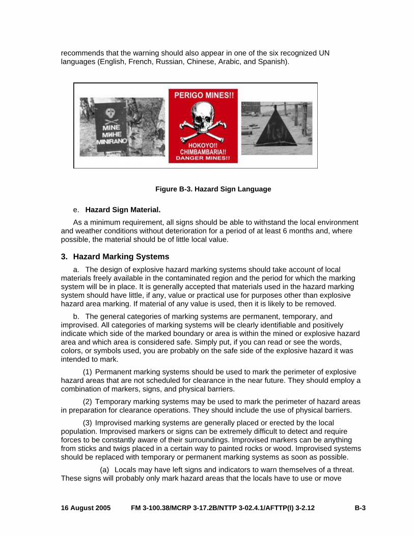
recommends that the warning should also appear in one of the six recognized UN languages (English, French, Russian, Chinese, Arabic, and Spanish).
Figure B-3. Hazard Sign Language
e. Hazard Sign Material. As a minimum requirement, all signs should be able to withstand the local environment
and weather conditions without deterioration for a period of at least 6 months and, where possible, the material should be of little local value.
3. Hazard Marking Systems a. The design of explosive hazard marking systems should take account of local
materials freely available in the contaminated region and the period for which the marking system will be in place. It is generally accepted that materials used in the hazard marking system should have little, if any, value or practical use for purposes other than explosive hazard area marking. If material of any value is used, then it is likely to be removed.
b. The general categories of marking systems are permanent, temporary, and improvised. All categories of marking systems will be clearly identifiable and positively indicate which side of the marked boundary or area is within the mined or explosive hazard area and which area is considered safe. Simply put, if you can read or see the words, colors, or symbols used, you are probably on the safe side of the explosive hazard it was intended to mark.
(1) Permanent marking systems should be used to mark the perimeter of explosive hazard areas that are not scheduled for clearance in the near future. They should employ a combination of markers, signs, and physical barriers.
(2) Temporary marking systems may be used to mark the perimeter of hazard areas in preparation for clearance operations. They should include the use of physical barriers.
(3) Improvised marking systems are generally placed or erected by the local population. Improvised markers or signs can be extremely difficult to detect and require forces to be constantly aware of their surroundings. Improvised markers can be anything from sticks and twigs placed in a certain way to painted rocks or wood. Improvised systems should be replaced with temporary or permanent marking systems as soon as possible.
(a) Locals may have left signs and indicators to warn themselves of a threat. These signs will probably only mark hazard areas that the locals have to use or move
16 August 2005 FM 3-100.38/MCRP 3-17.2B/NTTP 3-02.4.1/AFTTP(I) 3-2.12 B-3
through. The full perimeter may not be marked at all. Because of their improvised nature, these types of signs generally do not give a clue as to where or what the threat is. Always try to get local assistance in identifying the indicators and what they mean, Such as: Where are the mines or UXO? Is it marking a single hazard? Is it marking a safe route?
(b) Improvised markers can be manmade or natural materials. Manmade materials are generally obvious but weathering and age can reduce the visual impact and ease with which you can spot them. Markers using natural materials can be extremely difficult to spot such as sticks or broken branches. They too deteriorate very quickly.
(c) Piled stones, sticks, or pickets may be used to effectively mark hazard areas. Stones/rocks are common materials that are not valuable and, therefore, will not be stolen. Stones should be painted at the apex and, where possible, the hazard warning sign should be positioned into the cairn or fixed to a stick or metal pole from above the stone apex.
(d) Painted rocks or other items signifying danger should normally be colored red, but if that color has cultural sensitivities, any other ‘strong’ color may be used. The markers should be placed along the edge closest to the explosive hazard. The basic rule is that no one should cross the line indicated by the markers.
(e) White rocks or other markers should be used to signal ‘safety’ and should be placed along the edges of usable areas, before the line of colored rocks used to mark the edges of danger areas (i.e., on the usable side of the hazard area) and between two rows of colored rocks (e.g., a safety lane between two hazard areas so that the safety lane is obvious). The space between markers should be no more than 5 m except at turning points, where the spacing should be reduced to approximately 2 m.
(f) Improvised marking systems can be used by military forces, but only when materials are unavailable to construct permanent or temporary marking systems or when conditions and circumstances prevent their use. Commanders must ensure that all forces operating in and around areas marked with improvised systems can identify them. Caution should be taken when considering the types of materials to use to construct improvised markers. Items such as lumber, pickets, bricks, or other items of construction material may be valuable to indigenous personnel for personal use and could be removed.
(g) Improvised marking methods should become a part of the national and local mine awareness programs in order to inform and educate the local population about their meaning and function. This education has a secondary function, which is to stop the removal of minefield marking and warning signs.
4. Permanent Hazard Marking System Specifications The design of permanent explosive hazard marking systems should include a
combination of markers, signs, and physical barriers that clearly identify the boundary of the explosive hazard area.
a. Markers and Signs. Hazard marking symbols must be clearly visible. Markers and signs must clearly identify which side of the marked boundary is considered to be within the explosive hazard area and which side is considered to be safe. The warning sign should be clearly displayed facing outwards from the mined area or suspected hazardous area.
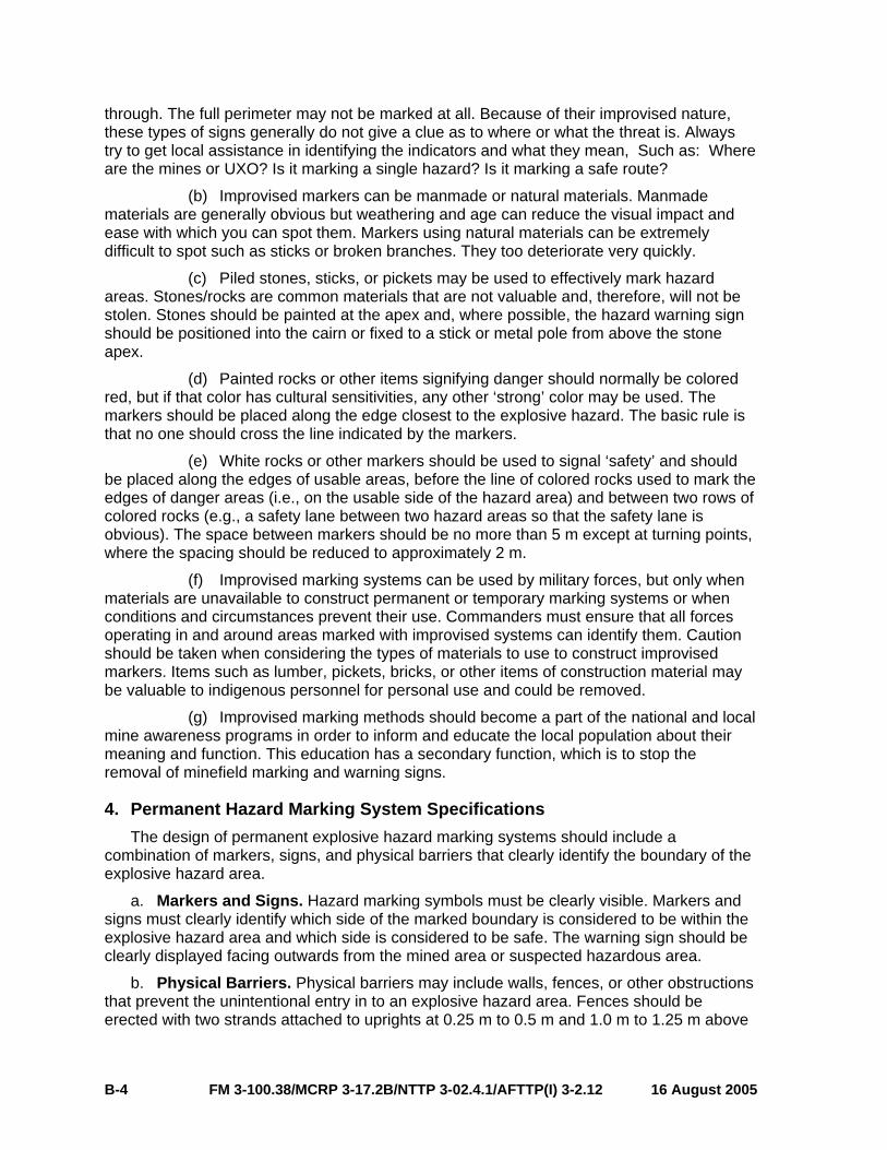
b. Physical Barriers. Physical barriers may include walls, fences, or other obstructions that prevent the unintentional entry in to an explosive hazard area. Fences should be erected with two strands attached to uprights at 0.25 m to 0.5 m and 1.0 m to 1.25 m above
FM 3-100.38/MCRP 3-17.2B/NTTP 3-02.4.1/AFTTP(I) 3-2.12 16 August 2005 B-4
the ground. (See figure B-4.) Fencing strands may be of any suitable durable material including wire, string, synthetic cord, or tape. Uprights may include trees, buildings, or existing structures and posts erected as part of the warning system and should be positioned not more than 15 m apart. Hazard signs are to be attached to the top strand of the fence not more than 30 m apart and within 5 m of each turning point. If necessary, they may also be attached to uprights.
not more than 30m
not more than 15m
0.25m - 0.5m
1.0m - 1.25m
Figure B-4. Minefield Fencing
c. Measurement Standards. All countries should use a uniform method (metric is preferred) with bearings in either mils or degrees and, where possible, using magnetic bearings. The primary global positioning system (GPS) coordinate system will be in longitude and latitude and the Grid Reference System. The secondary coordinate systems can be the local reference system. The following are technical parameters for identifying and measuring key survey points:
(1) Prominent Landmarks. They must be easily recognized and of a permanent nature. The exact position must be identified by GPS longitude/latitude and, where possible, an 8-digit grid reference.
(2) Benchmarks. Benchmarks are a permanent point of reference used as a navigational aid to mark the perimeter of the minefield. Benchmarks are to be numbered. Benchmarks can be made from metal, wood, or stone material. They will be in the configuration of three pickets driven flush into the ground in a triangular pattern with 1-meter spacing on each side. A picket will be placed upright in the center of the triangle. It must be visible from 30 m away. The apex of the benchmark should be aligned to any intermediate markers or to the minefield start point. Benchmarks should be painted a prominent color.
16 August 2005 FM 3-100.38/MCRP 3-17.2B/NTTP 3-02.4.1/AFTTP(I) 3-2.12 B-5

(3) Turning Points. Turning points should be distinctively marked with a marker (steel, wood, or stone) in the center of the lane at the turning point and a marker 1 m on each side of the turning point in the center of the lane. The turning point should be located using bearings and distances from a previous turning point or benchmark. They will also be given coordinates. GPS will not be used for fixing coordinates of turning or intermediate points unless it has a maximum error of ±5 cm.
(4) Intermediate Points. Intermediate points are to be marked between turning points to ensure that the direction between points is on a known fixed line that can be easily and accurately followed.
5. Hazard Marking System Maintenance The unit that constructs or emplaces the hazard marking system must:
a. Mark the hazardous area(s) in a manner consistent with this publication.
b. Brief the affected communities and local authorities on the hazard marking system.
c. Transfer ‘ownership’ of the hazard marking systems to the communities at risk and explain the need for its maintenance. This handover should be formally documented to allocate the responsibility for the maintenance to the local community. The local population must be encouraged to be responsible for the maintenance of the explosive hazard marking systems in their immediate areas. Material, such as mine signs and fencing, should be held in a central location in order that resources can be allocated to minefield tasks.
d. Conduct regular inspections of the hazard marking system. In the absence of any local authority or stable resident community, the unit that constructed or emplaced the marking system should make arrangements to maintain it until such time as the area is cleared of explosive hazards or until ordered to vacate the area. If possible, the unit should then seek to transfer the responsibility for its maintenance to the local authorities, a demining organization, or any other competent authority.
FM 3-100.38/MCRP 3-17.2B/NTTP 3-02.4.1/AFTTP(I) 3-2.12 16 August 2005 B-6

Appendix C
REPORTING UXO
1. Purpose This appendix implements STANAG 2143. The EH SPOTREP is a timely and detailed,
2-way reporting system; it clearly identifies the location of the UXO hazard, briefly describes the hazard, the priority for clearing, and the unit(s) affected. The EH SPOTREP is the first-echelon report that is sent when an observer detects UXO. Units can use the report to request help in handling a UXO hazard if the unit cannot reduce the hazard either by using protective works or moving away from the UXO. The report also assists the commander to set priorities based on the situation. The report consists of nine lines and is sent by the fastest means available. (See table C-1.)
2. Routing Forward the EH SPOTREP through the chain of command. Each commander in the
chain who receives/reviews the report may change the priority to reflect the current tactical situation or projected battle plan. Each commander in the chain is responsible for forwarding the EH SPOTREP through command channels and ensuring that the proper priority is set for each report. When a commander changes the original priority, the higher-level commander must inform subordinate commands, especially the initial reporting unit. Based on METT-T (with the Army adding a “C” for civil considerations), engineer forces use the EH SPOTREP to prioritize and sequence their response to breaching, clearing, and proofing mobility obstacles. EOD forces use the EH SPOTREP to help sequence their response to all UXO incidents.
16 August 2005 FM 3-100.38/MCRP 3-17.2B/NTTP 3-02.4.1/AFTTP(I) 3-2.12 C-1
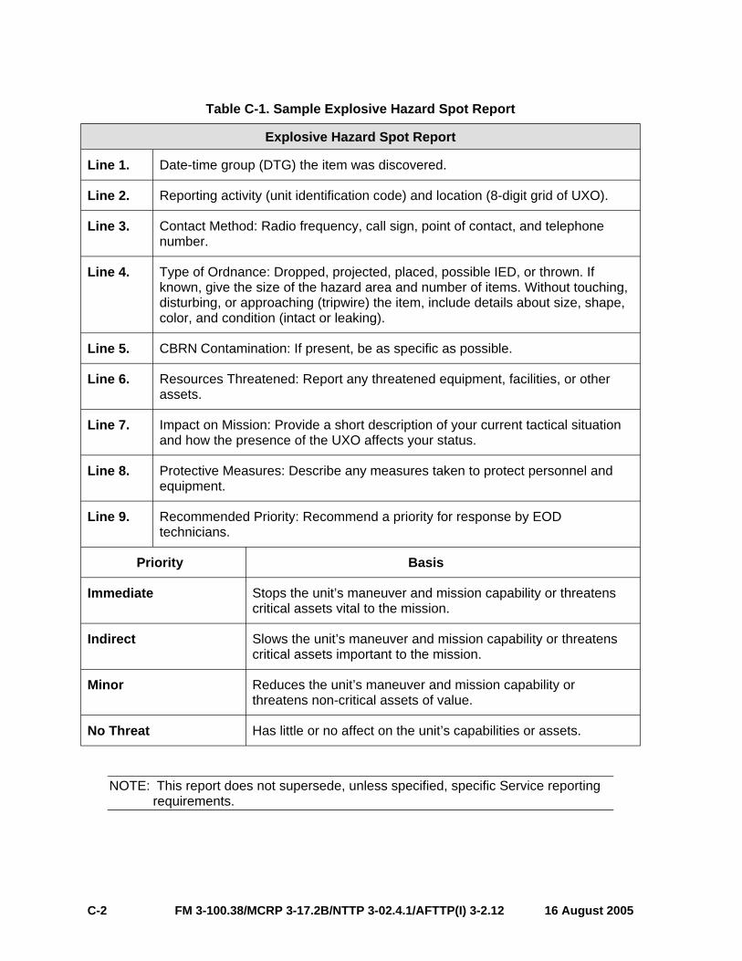
Table C-1. Sample Explosive Hazard Spot Report
Explosive Hazard Spot Report
Line 1. Date-time group (DTG) the item was discovered.
Line 2. Reporting activity (unit identification code) and location (8-digit grid of UXO).
Line 3. Contact Method: Radio frequency, call sign, point of contact, and telephone number.
Line 4. Type of Ordnance: Dropped, projected, placed, possible IED, or thrown. If known, give the size of the hazard area and number of items. Without touching, disturbing, or approaching (tripwire) the item, include details about size, shape, color, and condition (intact or leaking).
Line 5. CBRN Contamination: If present, be as specific as possible.
Line 6. Resources Threatened: Report any threatened equipment, facilities, or other assets.
Line 7. Impact on Mission: Provide a short description of your current tactical situation and how the presence of the UXO affects your status.
Line 8. Protective Measures: Describe any measures taken to protect personnel and equipment.
Line 9. Recommended Priority: Recommend a priority for response by EOD technicians.
Priority Basis
Immediate Stops the unit’s maneuver and mission capability or threatens critical assets vital to the mission.
Indirect Slows the unit’s maneuver and mission capability or threatens critical assets important to the mission.
Minor Reduces the unit’s maneuver and mission capability or threatens non-critical assets of value.
No Threat Has little or no affect on the unit’s capabilities or assets.
NOTE: This report does not supersede, unless specified, specific Service reporting requirements.
FM 3-100.38/MCRP 3-17.2B/NTTP 3-02.4.1/AFTTP(I) 3-2.12 16 August 2005 C-2

Appendix D
PROTECTIVE MEASURES
There are three methods to protect personnel and equipment: evacuate, isolate, or barricade (or any combination thereof).
1. Evacuate When possible, evacuation of all personnel and equipment is the best protective
measure. See table D-1 for minimum evacuation distances. Allow occupation of the area only by mission essential personnel and equipment. After evacuating all personnel and equipment, allow movement within the area only for essential operations. Use barricades to protect mission-essential personnel and equipment that must stay in the area. (See paragraph 3, this appendix, for additional information on barricades.) Personnel who must remain in the area should also wear all protective equipment (to include Kevlar helmets and vests).
Table D-1. Evacuation Distances
EVACUATION DISTANCES
Explosive Weight (pounds) Evacuation Distance (meters)
27 or less 350
30 360
35 380
40 400
45 410
50 430
100 540
150 610
200 670
250 730
300 770
400 850
500 910
16 August 2005 FM 3-100.38/MCRP 3-17.2B/NTTP 3-02.4.1/AFTTP(I) 3-2.12 D-1
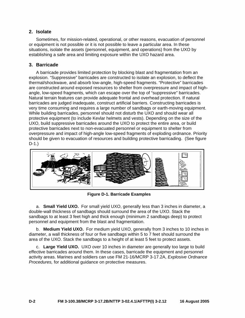
2. Isolate Sometimes, for mission-related, operational, or other reasons, evacuation of personnel
or equipment is not possible or it is not possible to leave a particular area. In these situations, isolate the assets (personnel, equipment, and operations) from the UXO by establishing a safe area and limiting exposure within the UXO hazard area.
3. Barricade A barricade provides limited protection by blocking blast and fragmentation from an
explosion. “Suppressive” barricades are constructed to isolate an explosion, to deflect the thermal/shockwave, and absorb low-angle, high-speed fragments. “Protective” barricades are constructed around exposed resources to shelter from overpressure and impact of high-angle, low-speed fragments, which can escape over the top of “suppressive” barricades. Natural terrain features can provide adequate frontal and overhead protection. If natural barricades are judged inadequate, construct artificial barriers. Constructing barricades is very time consuming and requires a large number of sandbags or earth-moving equipment. While building barricades, personnel should not disturb the UXO and should wear all protective equipment (to include Kevlar helmets and vests). Depending on the size of the UXO, build suppressive barricades around the UXO to protect the entire area, or build protective barricades next to non-evacuated personnel or equipment to shelter from overpressure and impact of high-angle low-speed fragments of exploding ordnance. Priority should be given to evacuation of resources and building protective barricading. (See figure D-1.)
Figure D-1. Barricade Examples
a. Small Yield UXO. For small yield UXO, generally less than 3 inches in diameter, a double-wall thickness of sandbags should surround the area of the UXO. Stack the sandbags to at least 3 feet high and thick enough (minimum 2 sandbags deep) to protect personnel and equipment from the blast and fragmentation.
b. Medium Yield UXO. For medium yield UXO, generally from 3 inches to 10 inches in diameter, a wall thickness of four or five sandbags within 5 to 7 feet should surround the area of the UXO. Stack the sandbags to a height of at least 5 feet to protect assets.
c. Large Yield UXO. UXO over 10 inches in diameter are generally too large to build effective barricades around them. In these cases, barricade the equipment and personnel activity areas. Marines and soldiers can use FM 21-16/MCRP 3-17.2A, Explosive Ordnance Procedures, for additional guidance on protective measures.
FM 3-100.38/MCRP 3-17.2B/NTTP 3-02.4.1/AFTTP(I) 3-2.12 16 August 2005 D-2

Appendix E
UXO GRAPHICS SYMBOLS
1. Purpose This appendix discusses procedures and provides examples of map symbols used with
map overlays for tracking/plotting UXO. All units can benefit by tracking and maintaining situational awareness of UXO within their AO. Operational and tactical commanders and staffs can utilize the graphics in this appendix to track all UXO hazards within their AO.
2. Procedures a. Plotting Requirements. Every unit should maintain locations of UXO within their
battlespace. EOD and engineer units are responsible for accurately recording the location of UXO incidents within their AO. This includes, at a minimum, DTG reported, type/quantity, grid location, and DTG the UXO was cleared. As additional information becomes available, the joint force engineer disseminates the information through the J-2/J-3 to other organizations operating within the JOA. The joint force EOD officer will provide appropriate information to the joint force engineer to incorporate into the engineer obstacle overlay.
b. Plotting Procedures. Plot UXO on an overlay or on a map using the following guidelines:
(1) Graphic Symbols. Three types of graphic symbols may be used when plotting UXO: point UXO, area UXO, and graphics for mines/minefields.
(a) Point UXO. The graphic control measure to depict a point UXO incident is an inverted triangle with the letters “UXO” printed in the center of the triangle. The bottom point of the triangle represents the exact location of the UXO; using the extended line option, the open end of the extended line represents the exact location of the UXO. The joint force EOD officer may assign a numerical value to the hazard for consistent tracking and historical information. (See figure E-1.)
Figure E-1. Graphic for a Point UXO
(b) UXO Area. The graphic symbol for a UXO area is a line drawn around the perimeter of the area, with “UXO” and a numerical value relating to its order of reception
16 August 2005 FM 3-100.38/MCRP 3-17.2B/NTTP 3-02.4.1/AFTTP(I) 3-2.12 E-1

placed on both sides of the perimeter line. The area in the center of the UXO hazard area will include the DTG of discovery or when the incident was fired, whichever is earlier, the type of UXO (including either US or foreign), and the DTG confirmed. (See figure E-2.)
Figure E-2. Graphic for a UXO Area
(c) Mine/Minefields. There are several different graphic symbols for mines/minefields to provide a better visual graphic of the hazard. Figure E-3 provides a comprehensive list of available graphics for mines/minefields.
(2) Abbreviations. When using abbreviations to describe the type of UXO, use the abbreviations in appendix F, table F-2 to refer to the specific UXO type.
FM 3-100.38/MCRP 3-17.2B/NTTP 3-02.4.1/AFTTP(I) 3-2.12 16 August 2005 E-2

Figure E-3. Mine and Minefield Graphics
16 August 2005 FM 3-100.38/MCRP 3-17.2B/NTTP 3-02.4.1/AFTTP(I) 3-2.12 E-3
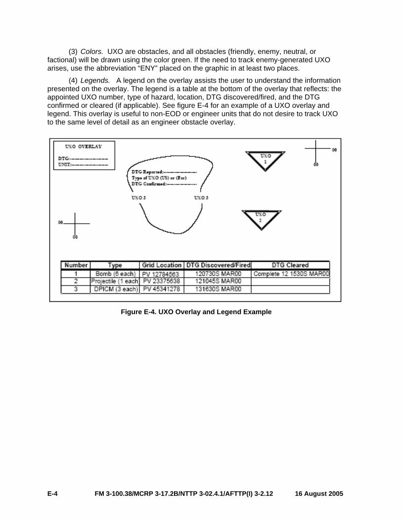
(3) Colors. UXO are obstacles, and all obstacles (friendly, enemy, neutral, or factional) will be drawn using the color green. If the need to track enemy-generated UXO arises, use the abbreviation “ENY” placed on the graphic in at least two places.
(4) Legends. A legend on the overlay assists the user to understand the information presented on the overlay. The legend is a table at the bottom of the overlay that reflects: the appointed UXO number, type of hazard, location, DTG discovered/fired, and the DTG confirmed or cleared (if applicable). See figure E-4 for an example of a UXO overlay and legend. This overlay is useful to non-EOD or engineer units that do not desire to track UXO to the same level of detail as an engineer obstacle overlay.
Figure E-4. UXO Overlay and Legend Example
FM 3-100.38/MCRP 3-17.2B/NTTP 3-02.4.1/AFTTP(I) 3-2.12 16 August 2005 E-4
Appendix F
OBSTACLE NUMBERING AND TRACKING
1. Obstacle Numbering a. Purpose.
(1) When an obstacle is conceived in the planning process it is given a tracking number based on the key elements of general information (country, unit, type of obstacle, status, and location). The same elements of information are required when recording discovered obstacles.
(2) Enemy obstacles do not need to be tracked using a different numbering system. Once emplaced or discovered, all obstacles have the same impact for reporting requirements and must be accounted for and cleared once hostilities have ended.
(3) The obstacle numbering system has two primary purposes. These purposes are:
(a) To give units a method of recording, organizing, and tracking emplaced and discovered obstacles.
(b) Provide a record of emplaced and discovered obstacles to follow on units or organizations for awareness or possible clearance.
(4) The obstacle numbering system shown in table F-1 consists of 21 alphanumeric characters subdivided into six distinct fields. The obstacle number is designated by the headquarters (HQ) that authorized the placement and planning or the HQ that entered the discovered obstacle information into the obstacle database. All obstacles regardless of the emplacing nation are tracked and reported using the same numbering system. An obstacle number provides the following information concerning an individual obstacle. These include:
(a) The country responsible for the initial placement.
(b) The HQ that authorized or discovered the obstacle emplacement or discovery.
(c) The individual obstacle type.
(d) The individual obstacle number.
(e) The status of the obstacle.
(f) The 100,000 meter identifier and a 6-digit grid.
b. Example. The following example depicts a minefield planned by a US division at grid WT123456. See figure F-1 and table F-1 for a detailed explanation of the example.
16 August 2005 FM 3-100.38/MCRP 3-17.2B/NTTP 3-02.4.1/AFTTP(I) 3-2.12 F-1

USA D001 MF 001 P WT123456
A B C FD E
Figure F-1. Obstacle Number Scenario
(1) The obstacle numbering system is not designed to be all inclusive of every variation of individual obstacle types. Table F-2 gives units a 2-letter character used for a general description of the obstacle types. All additional details about the obstacle should be referenced in the individual obstacle report. For example, the 1st US Division decides to emplace an area denial antipersonnel mine and/or remote antiarmor mine minefield at WT123456. The obstacle number which is USAD001(MF)001PWT123456 only denotes that the obstacle is a minefield. The delivery means, mine type, and other details will be found in the obstacle report. The number will simply change field E from “P” for planned to “A” for active.
(2) Units must have a standard operating procedure (SOP) to track and disseminate obstacle intelligence (OBSTINTEL). All obstacles (whether enemy, friendly, or unknown) must be tracked using the same system.
(3) Planned obstacles should not be entered into a tracking database until they have been initiated. Once a planned obstacle is initiated it must become part of the mobility input to the COP and populate on unit overlays.
(4) It is important to note that once an obstacle is input into the tracking database it is permanent. Even once an obstacle has been cleared, such as in the case of IEDs, the tracking status is changed (detonated, removed, or disarmed) and remains in the database.
FM 3-100.38/MCRP 3-17.2B/NTTP 3-02.4.1/AFTTP(I) 3-2.12 16 August 2005 F-2
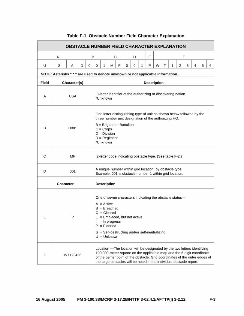
Table F-1. Obstacle Number Field Character Explanation
OBSTACLE NUMBER FIELD CHARACTER EXPLANATION
A B C D E F
U S A D 0 0 1 M F 0 0 1 P W T 1 2 3 4 5 6
NOTE: Asterisks " * " are used to denote unknown or not applicable information.
Field Character(s) Description
A USA 3-letter identifier of the authorizing or discovering nation. *Unknown
B D001
One letter distinguishing type of unit as shown below followed by the three number unit designation of the authorizing HQ.
B = Brigade or Battalion C = Corps D = Division R = Regiment *Unknown
C MF 2-letter code indicating obstacle type. (See table F-2.)
D 001 A unique number within grid location, by obstacle type. Example: 001 is obstacle number 1 within grid location.
Character Description
E P
One of seven characters indicating the obstacle status—
A = Active B = Breached C = Cleared E = Emplaced, but not active I = In progress P = Planned
S = Self-destructing and/or self-neutralizing U = Unknown
F WT123456
Location —The location will be designated by the two letters identifying 100,000-meter-square on the applicable map and the 6-digit coordinate of the center point of the obstacle. Grid coordinates of the outer edges of the large obstacles will be noted in the individual obstacle report.
16 August 2005 FM 3-100.38/MCRP 3-17.2B/NTTP 3-02.4.1/AFTTP(I) 3-2.12 F-3

Table F-2. Obstacle Types
OBSTACLE TYPES
AH 6Aerial hazard DM 1Demolition LS Landslide
BE Berm DT Dragon teeth MF 2Minefield
BP Beam post EX 4Explosive hazard
(UXO, IED) OT Other
BT Booby traps FB Falling block TD Antitank ditch
CA Contaminated area FL Flooding WO 3Wire
CR Road crater DG Dry gap WW Waterway
LG 5Log DU Dummy/decoy UR Urban rubble (car, bus, equipment)
WH 7Water hazard
1Annotate the target description in the remarks of the obstacle report. 2Annotate the type of delivery system and munition in the remarks of the obstacle report. 3Annotate the type of wire obstacle in remarks of the obstacle report. 4Annotate the type of explosive hazard (such as IED or UXO) in the remarks of the obstacle report. 5Annotate the type of log obstacle (such as crib, abatis, or hurdle) in the remarks portion of the obstacle report.6Annotate the type of aerial hazard (such as towers, antennas, or high-tension wires) in the remarks portion of the obstacle report. 7Annotate the type of water hazard (such as wire or nets) in the remarks of the obstacle report.
2. Obstacle Tracking a. Pattern Analysis Pattern analysis is the ability to observe a selection of events or actions over a period of
time in a defined location or area. It is used to discover likely patterns or similarities that lead to a logical conclusion that the action or event will occur again in the same location. For instance, over a period of weeks or months a unit encounters IEDs along the same 1kilometer stretch of the route in different locations, but basically have the same design or makeup. Even though these IEDs (once detonated or disarmed) do not populate the COP, their locations plotted over time begin to show a pattern that can be analyzed and used to possibly prevent further occurrences by killing or capturing the unit, person, or persons responsible for emplacing the IEDs. The same pattern analysis can be applied to more conventional obstacles in a tactical environment.
FM 3-100.38/MCRP 3-17.2B/NTTP 3-02.4.1/AFTTP(I) 3-2.12 16 August 2005 F-4

b. Post-Conflict Applications Ultimately conflict in a region ends and rebuilding must begin. One of the most difficult
tasks for a rebuilding nation is the clearance or removal of unexploded or other hazardous obstacles. Many countries suffer untold civilian casualties from old unrecovered obstacles from past conflicts. The obstacle numbering system and eventually the minefield database can be used at the international level to identify, mark, and eventually clear these hazards in a post-conflict environment.
3. Other Considerations: Self-Destructing and/or Self-Neutralizing Obstacles Self-destructing and/or self-neutralizing (SD/SN) obstacles are becoming more common
on the modern battlefield. They are part of an ever evolving tool for commanders in the field for more responsive countermobility solutions to tactical and operational problems. They also attempt to reduce the post-conflict hazard to civilian populations. However, SD/SN obstacles still have a small failure rate. For this reason, all SD/SN obstacles will be given an "S" status in field "E", obstacle status, once it reaches its SD/SN time. This lets units and other organizations know that a hazard still exists even though it may be greatly reduced. As with any other obstacle, a SD/SN obstacle WILL NOT receive a "C" status unless the area is physically cleared.
16 August 2005 FM 3-100.38/MCRP 3-17.2B/NTTP 3-02.4.1/AFTTP(I) 3-2.12 F-5

This page intentionally left blank.

Appendix G
UXO TRAINING
1. Background At a minimum, unit commanders should ensure their forces receive training on
identification of UXO and the proper conduct of operations around UXO. This appendix provides an example of basic skills that personnel should employ to improve operational safety in the proximity of UXO. These skills serve as guidelines for UXO training—they are not intended to detract from a Service specific training requirement.
2. Training Curriculum a. Introduction. UXO is inherently hazardous! The deadly capabilities of UXO are
categorized as conventional, chemical, biological, or any combination thereof. They pose a risk of injury or death to all personnel. They take the form of missiles, bombs, rockets, mines or other devices and can range in size from very small to extremely large.
b. Training. If a UXO hazard, or object suspected to be unexploded ordnance is discovered, there are four important steps to take: identify, mark, evacuate, and report.
(1) Identify. See appendix A for additional guidance. When a UXO hazard is discovered, proper identification is important to report the hazard accurately. Accurate reporting of the hazard assists the experts in determining clearance requirements and accurately warning friendly units of the hazard. Take the following steps upon recognizing a UXO hazard:
(a) Identify the type UXO, if possible (known ordnance).
(b) Note features (categories such as dropped, projected, thrown, or placed) and size, shape, color, and condition of the ordnance (intact or leaking).
(2) Mark. Marking the hazard warns other friendly personnel and provides a locating mechanism for clearance by qualified personnel. See appendix B for additional guidance. Take the following steps when marking UXO:
(a) Mark the hazard from where you are. Do not approach any closer to the hazard.
(b) Use the standard UXO or mine markers; if standard markers are not available, use whatever material (such as engineer tape or chemical lights) available.
(c) Ensure markings are visible in all directions, even at night.
(3) Evacuate. Take the following steps:
(a) Evacuate all personnel and equipment from the area.
(b) If evacuation is impossible, isolate or barricade the area. See appendix D for additional information on isolation and barricade techniques.
(4) Report. Take the following steps to report a UXO hazard:
(a) Report the incident using the 9-line format at appendix C.
16 August 2005 FM 3-100.38/MCRP 3-17.2B/NTTP 3-02.4.1/AFTTP(I) 3-2.12 G-1

(b) If sending the report by radio, transmit from a minimum-safe distance (100 meters) to avoid detonation. Reporting by radio can send an electrical pulse to the hazard, causing detonation.
(c) Provide all pertinent details: size, shape, color, condition, landmarks, and grid coordinates.
FM 3-100.38/MCRP 3-17.2B/NTTP 3-02.4.1/AFTTP(I) 3-2.12 16 August 2005 G-2
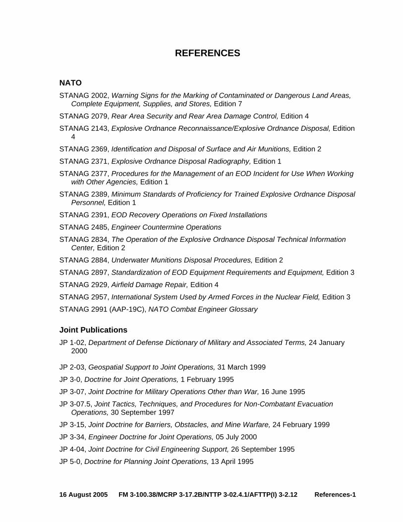
4
REFERENCES
NATO STANAG 2002, Warning Signs for the Marking of Contaminated or Dangerous Land Areas,
Complete Equipment, Supplies, and Stores, Edition 7
STANAG 2079, Rear Area Security and Rear Area Damage Control, Edition 4
STANAG 2143, Explosive Ordnance Reconnaissance/Explosive Ordnance Disposal, Edition
STANAG 2369, Identification and Disposal of Surface and Air Munitions, Edition 2
STANAG 2371, Explosive Ordnance Disposal Radiography, Edition 1
STANAG 2377, Procedures for the Management of an EOD Incident for Use When Working with Other Agencies, Edition 1
STANAG 2389, Minimum Standards of Proficiency for Trained Explosive Ordnance Disposal Personnel, Edition 1
STANAG 2391, EOD Recovery Operations on Fixed Installations
STANAG 2485, Engineer Countermine Operations
STANAG 2834, The Operation of the Explosive Ordnance Disposal Technical Information Center, Edition 2
STANAG 2884, Underwater Munitions Disposal Procedures, Edition 2
STANAG 2897, Standardization of EOD Equipment Requirements and Equipment, Edition 3
STANAG 2929, Airfield Damage Repair, Edition 4
STANAG 2957, International System Used by Armed Forces in the Nuclear Field, Edition 3
STANAG 2991 (AAP-19C), NATO Combat Engineer Glossary
Joint Publications JP 1-02, Department of Defense Dictionary of Military and Associated Terms, 24 January
2000
JP 2-03, Geospatial Support to Joint Operations, 31 March 1999
JP 3-0, Doctrine for Joint Operations, 1 February 1995
JP 3-07, Joint Doctrine for Military Operations Other than War, 16 June 1995
JP 3-07.5, Joint Tactics, Techniques, and Procedures for Non-Combatant Evacuation Operations, 30 September 1997
JP 3-15, Joint Doctrine for Barriers, Obstacles, and Mine Warfare, 24 February 1999
JP 3-34, Engineer Doctrine for Joint Operations, 05 July 2000
JP 4-04, Joint Doctrine for Civil Engineering Support, 26 September 1995
JP 5-0, Doctrine for Planning Joint Operations, 13 April 1995
16 August 2005 FM 3-100.38/MCRP 3-17.2B/NTTP 3-02.4.1/AFTTP(I) 3-2.12 References-1

JP 5-00.2, Joint Task Force Planning Guidance and Procedures, 13 January 1999
Multi-Service Publications Ordnance Data (ORDATA) Series on compact disk, Enhanced International Deminer’s
Guide to UXO Identification, no date. Obtain disks (need to know) at e-mail: [email protected]
Technical Manual (TM ) (Army), Technical Order (TO) (Air Force), EOD Bulletin (Navy), 60A-1-1-7, Explosive Ordnance Disposal Procedures; Field Evaluation and Intelligence, 23 March 1999
AR 75-14/OPNAVINST 8027.1G/MCO 8027.1D/AFJI 32-3002, Interservice Responsibilities and Procedures for Explosive Ordnance Disposal, 14 February 1992
FM 4-30.16/MCRP 3-17.2C/NTTP 3-02.5/AFTTP(I) 3-2.32, Multiservice Procedures for Explosive Ordnance Disposal in a Joint Environment, October 2005
Army Note. The Army’s new numbering system for Field Manuals is the first number listed
below, followed by the old FM number.
AR 75-15, Policy for Explosive Ordnance Disposal, 22 February 2005
FM 1-02 (FM 101-5-1), MCRP 5-12A, Operational Terms and Graphics, 21 September 2004
FM 3-34 (FM 5-100), Engineer Operations, 2 January 2004
FM 3-34.2, Combined Arms Breaching Operations, 28 February 1991
FM 3-34.210 (FM 20-32), Mine/Countermine Operations, 29 May 1998
FM 3-90.13 (FM 90-7), Combined Arms Obstacle Integration, 29 September 1994
FM 3-90.11 (FM 3-34.2), Combined Arms Breaching Operations, 28 February 1991
FM 4-30.11 (FM 21-16), Unexploded Ordnance Procedures, 30 August 1994
FM 4-30.12 (FM 9-15), Explosive Ordnance Disposal Service and Unit Operations, 8 May 1996
FM 5-116, Engineer Operations Echelons Above Corps, 9 February 1999
FM 5-71-100, Division Engineer Combat Operations, 22 April 1993
FM 20-32, Mine/Countermine Operations, 29 May 1998
FM 90-7, Combined Arms Obstacle Integration, 29 September 1994
FM 100-15, Corps Engineer Operations, 6 June 1995
TM 43-0001-28, Army Ammunition Data Sheets for Artillery Ammunitions: Guns, Howitzers, Mortars, Recoilless Rifles, Grenade Launchers, and Artillery Fuses, 31 July 1996
TM 43-0001-29, Army Ammunition Data Sheets for Grenades, 30 June 1994
TM 43-0001-36, Army Ammunition Data Sheets for Land Mines, 1 September 1994
TM 43-0001-37, Army Ammunition Data Sheets: Military Pyrotechnics, 6 January 1994
GTA 9-12-1, Unexploded Ordnance (UXO) Procedures, 3 January 1992
References-2 FM 3-100.38/MCRP 3-17.2B/NTTP 3-02.4.1/AFTTP(I) 3-2.12 16 August 2005

Marine Corps MCRP 3-17.2A, Unexploded Ordnance Procedures, 30 August 1994
MCWP 3-2, Aviation Operations, April 1999
MCWP 3-16, Techniques and Procedures for Fire Support Planning/Coordination, March 1992
MCWP 3-17.2, Explosive Ordnance Disposal, December 1993
MCWP 4-11.5, Seabee Operations in the (MAGTF) Marine Amphibious Group Task Force, November 1997
MCO 3571.2, Explosive Ordnance Disposal Program, August 1990
Navy OPNAVINST 3501.93D, Projected Operational Environment and Required Operational
Capabilities for Naval Beach Groups and Their Elements, 29 August 1994
OPNAVINST 3501.97, Projected Operational Environment and Required Operational Capabilities for Explosive Ordnance Disposal Ground Forces, 26 January 1996
OPNAVINST 5450.46K, Naval Construction Force Policy, 25 May 1999
NWP 3-02.4, Explosive Ordnance Disposal, July 1997
NWP 4-04.1, Seabee Operations in the (MAGTF) Marine Amphibious Group Task Force, November 1997
Navy Supplemental Publication 409 MILSTRIP/MILSTRAP Desk Guide, Revised June 1998
US Naval Sea Systems Command, US Naval Mine Familiarization, January, 2000
Air Force AFPD 32-30, Explosive Ordnance Disposal, 20 July 1994
AFI 32-3001, EOD Program, 1 June 1998
AFI 33-360, Publications Management Program, 31 Jul 98
AFMAN 10-100, Airman's Manual, 1 June 2004
AFPAM 10-219, Volume 2, Pre-Attack and Disaster Preparations, 1 November 1996
AFPAM 10-219, Volume 3, Post-Attack and Post-Disaster Procedures, 1 April 1997
AFH 32-4014, Volume 4, USAF Ability to Survive and Operate Procedures in a Nuclear, Biological, and Chemical (NBC) Environment, 1 March 1998
AFVA 32-4022, USAF Unexploded Explosive Ordnance Recognition and Reporting Chart, 1 April 1999
16 August 2005 FM 3-100.38/MCRP 3-17.2B/NTTP 3-02.4.1/AFTTP(I) 3-2.12 References-3

This page intentionally left blank.

1
GLOSSARY
PART I – ABBREVIATIONS AND ACRONYMS
A - B AFDC Air Force Doctrine Center AFH Air Force handbook AFI Air Force Instruction AFMAN Air Force Manual AFPD Air Force Policy Document AFTTP(I) Air Force Tactics, Techniques, and Procedures (Interservice) AFVA Air Force Visual Aid ALSA Air Land Sea Application AO area of operations AR Army Regulation ARFOR Army forces ASP Ammunition Storage Point BCT brigade combat team
C
C2 command and control CBRN chemical, biological, radiological, and nuclear CBRNE chemical, biological, radiological, nuclear, and high yield explosives CBU cluster bomb unit CE civil engineer CEA captured enemy ammunition COP common operational picture
D
DOD Department of Defense DTG date-time group
E - I EOCA Explosive Ordnance Clearance Agent EODCC EOD Control Center
EOD explosive ordnance disposal FM field manual (Army) GPS global positioning system
HQ headquarters
IDN Initial Distribution Number
16 August 2005 FM 3-100.38/MCRP 3-17.2B/NTTP 3-02.4.1/AFTTP(I) 3-2.12 Glossary-1
IED improvised explosive device
J
J-2 intelligence staff section J-3 operations staff section J-4 logistics staff section J-5 plans staff section JEODOC joint explosive ordnance disposal operations center JFC joint force commander JFLCC joint force land component commander JOA joint operations area JP joint publication JRA joint rear area JRAC joint rear area coordinator JTF joint task force
M
MAGTF Marine air-ground task force MARFORLANT Marine Forces, Atlantic MARFORPAC Marine Forces, Pacific MCCDC US Marine Corps Combat Development Command MCO Marine Corps Order MCPDS Marine Corps Publication Distribution System MCRP Marine Corps Reference Publication MCWP Marine Corps Warfare Publication MEF Marine expeditionary force METT-T mission, enemy, terrain and weather, troops and support available,
time available (DOD) METT-TC mission, enemy, terrain and weather, troops and support available,
time available, and civil considerations (Army only) MEU Marine expeditionary unit MILSTRIP Military Standard Requisition and Issue Procedure MTTP multi-Service tactics, techniques, and procedures
N
NATO North Atlantic Treaty Organization NAVSUP Navy Supplement Publication NCF Naval construction force NTTP Navy tactics, techniques, and procedures NWDC Navy Warfare Development Command NWP Naval warfare publication
Glossary-2 FM 3-100.38/MCRP 3-17.2B/NTTP 3-02.4.1/AFTTP(I) 3-2.12 16 August 2005

O
OPCON operational control OPLAN operation plan OPNAVINST operational Naval instruction OPORD operation order Prime BEEF Prime Base Engineer Emergency Force
R - S
RED HORSE Rapid Engineers Deployable Heavy Operations Repair Squadron, Engineers
SD/SN self-destructing and/or self-neutralizing SEABEE Navy construction engineers SPOTREP spot report STANAG standardization agreement
T
TACON tactical control TF task force TM technical manual TPFDD time-phased force and deployment data TRADOC US Army Doctrine and Training Command TTP tactics, techniques, and procedures
U
UTC unit type codes UXO unexploded explosive ordnance
PART II – TERMS AND DEFINITIONS
area of operations - An operational area defined by the joint force commander for land and naval forces. Areas of operation do not typically encompass the entire operational area of the joint force commander, but should be large enough for component commanders to accomplish their missions and protect their forces. Also called AO. (JP1-02)
barricade - A structure composed essentially of concrete, earth, metal, or wood, or any combination thereof, and so constructed as to reduce or confine the blast effect and fragmentation of an explosion.
battlespace - The environment, factors, and conditions that must be understood to successfully apply combat power, protect the force, or complete the mission. This includes the air, land, sea, space, and the included enemy and friendly forces; facilities; weather; terrain; the electromagnetic spectrum; and the information environment within the operational areas and areas of interest. (JP 1-02)
16 August 2005 FM 3-100.38/MCRP 3-17.2B/NTTP 3-02.4.1/AFTTP(I) 3-2.12 Glossary-3

blast - The brief and rapid movement of air, vapor, or fluid away from a center of outward pressure, as in an explosion or in the combustion of rocket fuel: the pressure accompanying this movement. This term is commonly used for “explosion,” but the two terms may be distinguished.
booby trap - An explosive or nonexplosive device or other material, deliberately placed to cause casualties when an apparently harmless object is disturbed or a normally safe act is performed. (JP 1-02)
breach - (Army) A tactical mission task in which the unit employs all available means to break through or secure a passage through an enemy defense, obstacle, minefield, or fortification. (FM 3-90) (Marine Corps) The employment of any means available to break through or secure a passage through an obstacle.)
clearing operation - An operation designed to clear or neutralize all mines and obstacles from a route or area. (JP 1-02)
cluster bomb unit - An aircraft store composed of a dispenser and submunitions. Also called CBU. (JP 1-02)
combat service support - The essential capabilities, functions, activities, and tasks necessary to sustain all elements of operating forces in theater at all levels of war. Within the national and theater logistic systems, it includes but is not limited to that support rendered by service forces in ensuring the aspects of supply, maintenance, transportation, health services, and other services required by aviation and ground combat troops to permit those units to accomplish their missions in combat. Combat service support encompasses those activities at all levels of war that produce sustainment to all operating forces on the battlefield. Also called CSS. (JP 1-02)
combat support - Fire support and operational assistance provided to combat elements. Also called CS. (JP-102)
command and control - The exercise of authority and direction by a properly designated commander over assigned and attached forces in the accomplishment of the mission. Command and control functions are performed through an arrangement of personnel, equipment, communications, facilities, and procedures employed by a commander in planning, directing, coordinating, and controlling forces and operations in the accomplishment of the mission. Also called C2. (JP 1-02)
communications zone - Rear part of a theater of war or theater of operations (behind but contiguous to the combat zone) which contains the lines of communications, establishments for supply and evacuation, and other agencies required for the immediate support and maintenance of the field forces. Also called COMMZ. (JP 1-02)
countermine operation - In land mine warfare, an operation to reduce or eliminate the effects of mines or minefields. (JP 1-02)
countermobility operations - The construction of obstacles and emplacement of minefields to delay, disrupt, and destroy the enemy by reinforcement of the terrain. The primary purpose of countermobility operations is to slow or divert the enemy, to increase time for target acquisition, and to increase weapons effectiveness. (JP 1-02)
Glossary-4 FM 3-100.38/MCRP 3-17.2B/NTTP 3-02.4.1/AFTTP(I) 3-2.12 16 August 2005
defilade - 1. Protection from hostile observation and fire provided by an obstacle such as a hill, ridge, or bank. 2. A vertical distance by which a position is concealed from enemy observation. 3. To shield from enemy fire or observation by using natural or artificial obstacles. (JP 1-02)
dispenser - In air armament, a container or device which is used to carry and release submunitions. (JP 1-02)
explosive ordnance - All munitions containing explosives, nuclear fission or fusion materials, and biological and chemical agents. This includes bombs and warheads; guided and ballistic missiles; artillery, mortar, rocket, and small arms ammunition; all mines, torpedoes, and depth charges; demolition charges; pyrotechnics; clusters and dispensers; cartridge and propellant actuated devices; electro-explosive devices; clandestine and improvised explosive devices; and all similar or related items or components explosive in nature. (JP 1-02)
explosive ordnance disposal - The detection, identification, on-site evaluation, rendering safe, recovery, and final disposal of unexploded explosive ordnance. It may also include explosive ordnance which has become hazardous by damage or deterioration. Also called EOD. (JP 1-02)
forward arming and refueling point - A temporary facility - organized, equipped, and deployed by an aviation commander, and normally located in the main battle area closer to the area where operations are being conducted than the aviation unit's combat service area - to provide fuel and ammunition necessary for the employment of aviation maneuver units in combat. The forward arming and refueling point permits combat aircraft to rapidly refuel and rearm simultaneously. Also called FARP. (JP 1-02)
fratricide - The unintentional killing or wounding of friendly personnel by friendly firepower. (FM 3-0).
high-water mark - Properly, a mark left on a beach by wave wash at the preceding high water. It does not necessarily correspond to the high-water line. Because it can be determined by simple observation, it is frequently used in place of the high-water line, which can be determined only by a survey. When so used, it is called the high-water line. (JP 1-02)
improvised explosive device - A device placed or fabricated in an improvised manner incorporating destuctive, lethal, noxious, pyrotechnic, or incendiary chemicals and designed to destroy, incapacitate, harass, or distract. It may incorporate military stores, but is normally devised from nonmilitary components. Also called IED. (JP 1-02)
joint force commander - A general term applied to a combatant commander, subunified commander, or joint task force commander authorized to exercise combatant command (command authority) or operational control over a joint force. Also called JFC. (JP 1-02)
joint operations - A general term to describe military actions conducted by joint forces or by Service forces in relationships (e.g., support, coordinating authority) which, of themselves, do not create joint forces. (JP 1-02)
joint operations area - An area of land, sea, and airspace, defined by a geographic combatant commander or subordinate unified commander, in which a joint force commander (normally a joint task force commander)
16 August 2005 FM 3-100.38/MCRP 3-17.2B/NTTP 3-02.4.1/AFTTP(I) 3-2.12 Glossary-5
conducts military operations to accomplish a specific mission. Joint operations areas are particularly useful when operations are limited in scope and geographic area or when operations are to be conducted on the boundaries between theaters. Also called JOA. (JP 1-02)
Marine air-ground task force - The Marine Corps principal organization for all missions across the range of military operations, composed of forces task-organized under a single commander capable of responding rapidly to a contingency anywhere in the world. The types of forces in the Marine air-ground task force (MAGTF) are functionally grouped into four core elements: a command element, an aviation combat element, a ground combat element, and a combat service support element. The four core elements are categories of forces, not formal commands. The basic structure of the MAGTF never varies, though the number, size, and type of Marine Corps units comprising each of its four elements will always be mission dependent. The flexibility of the organizational structure allows for one or more subordinate MAGTFs to be assigned. Also called MAGTF. (JP 1-02)
mine - 1. In land mine warfare, an explosive or material, normally encased, designed to destroy or damage ground vehicles, boats, or aircraft, or designed to wound, kill, or otherwise incapacitate personnel. It may be detonated by the action of its victim, by the passage of time, or by controlled means. 2. In naval mine warfare, an explosive device laid in the water with the intention of damaging or sinking ships or of deterring shipping from entering an area. The term does not include devices attached to the bottoms of ships or to harbor installations by personnel operating underwater, nor does it include devices which explode immediately on expiration of a predetermined time after laying. (JP 1-02)
minefield - 1. In land warfare, an area of ground containing mines emplaced with or without a pattern. 2. In naval warfare, an area of water containing mines laid with or without a pattern. (JP 1-02)
mobility - A quality or capability of military forces which permits them to move from place to place while retaining the ability to fulfill their primary mission. (JP 102)
multinational operations - A collective term to describe military actions conducted by forces of two or more nations, usually undertaken within the structure of a coalition or alliance. (JP 1-02)
munition - A complete device charged with explosives, propellants, pyrotechnics, initiating composition, or nuclear, biological, or chemical material for use in military operations, including demolitions. Certain suitably modified munitions can be used for training, ceremonial, or nonoperational purposes. Also called ammunition. (Note: In common usage, "munitions" [plural] can be military weapons, ammunition, and equipment.) (JP 1-02)
nap-of-the-earth flight - Flight close to the Earth's surface during which airspeed, height, and/or altitude are adapted to the contours and cover of the ground in order to avoid enemy detection and fire. (JP 1-02)
obstacle - Any obstruction designed or employed to disrupt, fix, turn, or block the movement of an opposing force, and to impose additional losses in personnel,
Glossary-6 FM 3-100.38/MCRP 3-17.2B/NTTP 3-02.4.1/AFTTP(I) 3-2.12 16 August 2005

time, and equipment on the opposing force. Obstacles can be natural, manmade, or a combination of both. (JP 1-02)
operational control - Command authority that may be exercised by commanders at any echelon at or below the level of combatant command. Operational control is inherent in combatant command (command authority) and may be delegated within the command. When forces are transferred between combatant commands, the command relationship the gaining commander will exercise (and the losing commander will relinquish) over these forces must be specified by the Secretary of Defense. Operational control is the authority to perform those functions of command over subordinate forces involving organizing and employing commands and forces, assigning tasks, designating objectives, and giving authoritative direction necessary to accomplish the mission. Operational control includes authoritative direction over all aspects of military operations and joint training necessary to accomplish missions assigned to the command. Operational control should be exercised through the commanders of subordinate organizations. Normally this authority is exercised through subordinate joint force commanders and Service and/or functional component commanders. Operational control normally provides full authority to organize commands and forces and to employ those forces as the commander in operational control considers necessary to accomplish assigned missions; it does not, in and of itself, include authoritative direction for logistics or matters of administration, discipline, internal organization, or unit training. Also called OPCON. (JP 1-02)
operation plan - Any plan, except for the Single Integrated Operational Plan, for the conduct of military operations. Plans are prepared by combatant commanders in response to requirements established by the Chairman of the Joint Chiefs of Staff and by commanders of subordinate commands in response to requirements tasked by the establishing unified commander. Operation plans are prepared in either a complete format (OPLAN) or as a concept plan (CONPLAN). The CONPLAN can be published with or without a time-phased force and deployment data (TPFDD) file. a. OPLAN--An operation plan for the conduct of joint operations that can be used as a basis for development of an operation order (OPORD). An OPLAN identifies the forces and supplies required to execute the combatant commander's strategic concept and a movement schedule of these resources to the theater of operations. The forces and supplies are identified in TPFDD files. OPLANs will include all phases of the tasked operation. The plan is prepared with the appropriate annexes, appendixes, and TPFDD files as described in the Joint Operation Planning and Execution System manuals containing planning policies, procedures, and formats. Also called OPLAN. b. CONPLAN--An operation plan in an abbreviated format that would require considerable expansion or alteration to convert it into an OPLAN or OPORD. A CONPLAN contains the combatant commander's strategic concept and those annexes and appendixes deemed necessary by the combatant commander to complete planning. Generally, detailed support requirements are not calculated and TPFDD files are not
16 August 2005 FM 3-100.38/MCRP 3-17.2B/NTTP 3-02.4.1/AFTTP(I) 3-2.12 Glossary-7
prepared. c. CONPLAN with TPFDD--A CONPLAN with TPFDD is the same as a CONPLAN except that it requires more detailed planning for phased deployment of forces. Also called CONPLAN. See also operation order; time-phased force and deployment data. (JP 1-02)
operation order - A directive issued by a commander to subordinate commanders for the purpose of effecting the coordinated execution of an operation. Also called OPORD. (JP 1-02)
ordnance - Explosives, chemicals, pyrotechnics, and similar stores, e.g., bombs, guns and ammunition, flares, smoke, or napalm. (JP 1-02)
recovery - 1. In air (aviation) operations, that phase of a mission which involves the return of an aircraft to a land base or platform afloat. 2. The retrieval of a mine from the location where emplaced. 3. Actions taken to rescue or extract personnel for return to friendly control. 4. Actions taken to extricate damaged or disabled equipment for return to friendly control or repair at another location. (JP 1-02)
RED HORSE - Air Force units wartime-structured to provide heavy engineer capability. They have a responsibility across the operational area, are not tied to a specific base, and are not responsible for base operation and maintenance. These units are mobile, rapidly deployable, and largely self-sufficient for limited periods of time. (JP 1-02)
render safe procedures - The portion of the explosive ordnance disposal procedures involving the application of special explosive ordnance disposal methods and tools to provide for the interruption of functions or separation of essential components of unexploded explosive ordnance to prevent an unacceptable detonation. (JP 1-02)
scatterable mine - In land mine warfare, a mine laid without regard to classical pattern and which is designed to be delivered by aircraft, artillery, missile, ground dispenser, or by hand. Once laid, it normally has a limited life. (JP 102)
Service component command - A command consisting of the Service component commander and all those Service forces, such as individuals, units, detachments, organizations, and installations under that command, including the support forces that have been assigned to a combatant command or further assigned to a subordinate unified command or joint task force. (JP 1-02)
special operations forces - Those Active and Reserve Component forces of the Military Services designated by the Secretary of Defense and specifically organized, trained, and equipped to conduct and support special operations. Also called SOF. (JP 1-02)
spot report - A concise narrative report of essential information covering events or conditions that may have an immediate and significant effect on current planning and operations that is afforded the most expeditious means of transmission consistent with requisite security. Also called SPOTREP. (JP 1-02)
submunition - Any munition that, to perform its task, separates from a parent munition. (JP 1-02)
unexploded explosive ordnance - Explosive ordnance which has been primed, fused, armed or otherwise prepared for action, and which has been fired,
Glossary-8 FM 3-100.38/MCRP 3-17.2B/NTTP 3-02.4.1/AFTTP(I) 3-2.12 16 August 2005
dropped, launched, projected, or placed in such a manner as to constitute a hazard to operations, installations, personnel, or material and remains unexploded either by malfunction or design or for any other cause. Also called UXO. (JP 1-02)
unit type code - A Joint Chiefs of Staff developed and assigned code, consisting of five characters that uniquely identify a "type unit.” (JP 1-02)
weapons of mass destruction - Weapons that are capable of a high order of destruction and/or of being used in such a manner as to destroy large numbers of people. Weapons of mass destruction can be high explosives or nuclear, biological, chemical, and radiological weapons, but exclude the means of transporting or propelling the weapon where such means is a separable and divisible part of the weapon. Also called WMD. (JP 1-02)
16 August 2005 FM 3-100.38/MCRP 3-17.2B/NTTP 3-02.4.1/AFTTP(I) 3-2.12 Glossary-9

This page intentionally left blank.

INDEX
A Area of Operations (AO)I-3, II-4, III-2, III-3, E-1 Army Forces (ARFOR) ...............................III-2
B barricade........................... viii, D-1, D-2, G-1, 3 bombs ......................................... A-1, G-1, 5, 8 breaching ..................vii, I-1, II-2, II-5, III-3, C-1
C captured enemy ammunition (CEA) ..... I-1, II-2 CBRN.................... II-1, II-3, II-4, III-1, III-5, C-2 CBRNE .......................................................III-3
IImplementation Plan
Air Force .....................................................iii Army ........................................................... ii Marine Corps .............................................. ii Navy............................................................ ii
Improvised Explosive Device (IED) vii, I-1, II-1, II-4, III-3, C-2, F-2, F-4
J JEODOC......................................................II-4 joint force commander (JFC) ............... ii, II-2, 5
intelligence staff section (J-2) ..................II-3 operations staff section (J-3) ...................II-3 plans staff section (J-5) ...........................II-3
joint operations area (JOA).. II-2, II-4, II-5, III-2, E-1, 6
joint rear area (JRA) ....................................II-3 joint rear area coordinator (JRAC)...............II-3 joint task force (JTF) ............................ II-3, II-4
N Navy
naval construction force..........................III-4
O operation order (OPORD)... II-1, II-3, III-2, III-3,
7, 8 operational control (OPCON) ......... II-4, III-2, 7 operations plan (OPLAN) II-1, II-3, III-2, III-3, 7
R render safe........................................ I-1, II-4, 8
S SEABEE units..... See naval construction force
(NCF) spot report (SPOTREP)........... II-5, A-1, C-1, 8
U unexploded explosive ordnance (UXO).......... 8
graphics ..................................... viii, II-4, E-1 hazards ..................................... ii, vii, viii, I-2
air assault .............................................I-3 air base operations ...............................I-3 amphibious landing craft.......................I-3 armored forces......................................I-3 aviation forces.......................................I-3 civil infrastructure..................................I-3 civilians .................................................I-3 dismounted forces ................................I-3 ground based mobility ..........................I-2 non-armored vehicles ...........................I-3
obstacle overlay...viii, II-3, II-5, E-1, E-4, F-2 protective measures ..viii, II-1, II-4, C-2, D-1,
D-2 training .....................vii, II-2, II-4, II-5, G-1, 7
US Air Forcecivil engineer
command and control .........................III-5 mission................................................III-4 operational planning ...........................III-5 Prime BEEF ........................................III-4 RED HORSE ......................................III-5
EOD capabilities ..........................................III-4 mission................................................III-4
UTCs.......................................................III-5 War and Mobilization Plan
Prime BEEF ........................................III-5 RED HORSE ......................................III-5
US Armyengineers
command and control .........................III-2 mission................................................III-2 operational planning ...........................III-2
EOD command and control .........................III-1 mission................................................III-1 operational planning ...........................III-2 units ....................................................III-1
US Marine Corps engineers
mission................................................III-3
16 August 2005 FM 3-100.38/MCRP 3-17.2B/NTTP 3-02.4.1/AFTTP(I) 3-2.12 Index-1

EOD command and control................. III-3, III-4 mission ............................................... III-3 operational planning................... III-3, III-4
task organization ................................ III-3 US Navy
EOD mission ............................................... III-4
Index-2 FM 3-100.38/MCRP 3-17.2B/NTTP 3-02.4.1/AFTTP(I) 3-2.12 16 August 2005

FM 3-100.38 MCRP 3-17.2B NTTP 3-02.4.1
AFTTP(I) 3-2.12
16 August 2005 By Order of the Secretary of the Army:
Official: PETER J. SCHOOMAKER
General, United States Army Chief of Staff
SANDRA R. RILEY Administrative Assistant to the
Secretary of the Army 0525611
DISTRIBUTION: Active Army, Army National Guard, and US Army Reserve. To be distributed in accordance with IDN 115422, requirements for FM 3-100.38.
By Order of the Secretary of the Air Force:
BENTLEY B. RAYBURN Major General, USAF Commander Headquarters Air Force Doctrine Center
Air Force Distribution: F Supersedes AFTTP(I) 3-2.12, 23 August 2001.

MARINE CORPS PCN: 144 000105 00 PIN: 079260-000