multi-scale modelling of heterogeneous shell structures · in the case of a small strain...
TRANSCRIPT

HAL Id: hal-00714256https://hal-mines-paristech.archives-ouvertes.fr/hal-00714256
Submitted on 4 Jul 2012
HAL is a multi-disciplinary open accessarchive for the deposit and dissemination of sci-entific research documents, whether they are pub-lished or not. The documents may come fromteaching and research institutions in France orabroad, or from public or private research centers.
L’archive ouverte pluridisciplinaire HAL, estdestinée au dépôt et à la diffusion de documentsscientifiques de niveau recherche, publiés ou non,émanant des établissements d’enseignement et derecherche français ou étrangers, des laboratoirespublics ou privés.
Multi-scale modelling of heterogeneous shell structuresT.J. Massart, B.C.N. Mercatoris, Benoît Piezel, P. Berke, Lucien
Laiarinandrasana, Alain Thionnet
To cite this version:T.J. Massart, B.C.N. Mercatoris, Benoît Piezel, P. Berke, Lucien Laiarinandrasana, et al.. Multi-scalemodelling of heterogeneous shell structures. Computer Assisted Mechanics and Engineering Sciences,2011, 18, pp.53-71. <hal-00714256>

Computer Assisted Mechanics and Engineering Sciences, 18: 53–71, 2011.Copyright c© 2011 by Institute of Fundamental Technological Research, Polish Academy of Sciences
Multi-scale modelling of heterogeneous shell structures
T.J. Massart, B.C.N. Mercatoris, B. Piezel, P. BerkeBuilding, Architecture & Town Planning CP 194/2Universite Libre de Bruxelles (ULB)Avenue F.D. Roosevelt 50, 1050 Brussels, Belgiume-mail: [email protected]
L. Laiarinandrasana1, A. Thionnet1,21 Centre des Materiaux – Mines ParisTechCNRS UMR 7633, BP 87 – 91003 Evry Cedex, France2 Universite de Bourgogne, MirandeBP 47870, 21078 Dijon, France
This paper reviews multi-scale computational homogenisation frameworks for the non-linear behaviour ofheterogeneous thin planar shells. Based on a review of some of the currently available methods, a compu-tational homogenisation scheme for shells is applied on to representative volume elements for plain weavecomposites. The effect of flexural loading on the potential failure modes of such materials is analysed, fo-cusing on the reinforcement-matrix delamination mechanism. The attention is next shifted toward failurelocalisation in masonry unit cells. Subsequently, a recently developed computational FE2 solution schemeaccounting for damage localisation at structural scales based on RVE computations is applied.
Keywords: thin planar shells, computational homogenisation, failure, textile reinforced composites, ma-sonry.
1. INTRODUCTION
The non-linear and failure behaviour of heterogeneous materials is complex to represent computa-tionally due to the presence of numerous competing failure mechanisms, and the difficulty to for-mulate and identify constitutive laws able to incorporate them. Focusing the interest on mechanicalprocesses only, many examples of such situations can, for instance, be found in textile fabric [36]or woven reinforced composites [23, 42], in which delamination between the reinforcement and thematrix interacts with matrix cracking and delamination between plies. Such mechanisms may beparticularly active upon impact or when thin composite structures are loaded perpendicular to theirsurface. The same type of complex situation is encountered in masonry structures when crackingenters the picture, with potential damage localisation with evolving anisotropic properties of theoverall behaviour.As a complement to closed-form constitutive approaches, multi-scale approaches developed nowa-
days offer an alternative solution in the characterisation of periodic heterogeneous materials. Differ-ent multi-scale techniques have been developed in the past decades allowing postulating closed-formconstitutive laws at the scale of the constituents, on which the material parameters are a priori morestraightforward to identify. Substructuring methods based on a structural decomposition in non-overlapping subdomains have been proposed for heterogeneous materials, see for instance [11, 21],in which compatibility conditions are used to connect the discretisation of the subdomains to themacroscopic finite element mesh playing the role of a frame. Asymptotic homogenisation was ini-

54 T.J. Massart, B.C.N. Mercatoris, B. Piezel, P. Berke, L. Laiarinandrasana, A. Thionnet
tially presented for periodic heterogeneous materials in [7, 41], using an asymptotic expansion ofthe macroscopic variables which allows defining a boundary value problem on a representativevolume element (RVE) for each order under consideration, see [37]. This technique is still widelyused for composite materials [1, 2, 24]. Based on the scale separation assumption, computationalapproaches known as FE2 methods became popular over the last decade. They consist in com-puting numerically the average non-linear response of a heterogeneous microstructure by means ofaveraging theorems and a boundary value problem on a RVE [18, 25, 40]. These approaches werelater extended to account for structural scale localisation of degradation, either based on gradientenhancements in the scale transitions [26] or on microstructure-informed embedded discontinuitiesor cohesive zones used at the structural scale [31, 33, 44]. Another multi-scale approach recentlyproposed uses X-FEM, and consists in feeding the behaviour of structural scale equivalent dis-placement discontinuities with information extracted from the aggregation of all microstructuralmaterial instabilities present in a unit cell, see [5, 6].
Most of these efforts related to multi-scale modelling techniques were devoted until now to 2D or3D ’classical’ representations, assuming periodic boundary conditions on all the faces of 3D RVEs.However, complex heterogeneous materials may appear in shell-like structures such as laminated ortextile reinforced composites [22], truss core sandwich components [17, 45], or out-of-plane loadedmasonry structures [13]. To account properly for the shell kinematics, the periodicity constraintsneed to be relaxed on the top and bottom sides of a through-thickness RVE, and average curvatureshave to enter the scale transition relations. Extensions of multi-scale computational approachesto shell-like formulations were therefore recently proposed. Unit cell asymptotic homogenisationtechniques were used to determine the elastic properties of beam-like structures in [12], of compositeshell structures with orthotropic reinforcements in [14], and of periodic running bond masonry wallssubjected to out-of-plane loading in [13]. The computational homogenisation strategy was recentlyextended for structured thin sheets using the homogenisation of a through-thickness RVE based on asecond-order strategy [15, 20]. A more restricted periodic homogenisation procedure was presentedin [35] for the case of elastic Kirchhoff-Love masonry shells, later explored in [32] and [34] formasonry structures.
In the present contribution, computational homogenisation will be reviewed. RVE computationswill be performed for two types of materials. First, the effect of flexural loading will be scrutinisedfor plain weave composites. Second, localisation under bending in masonry will be analysed. Thepaper is structured as follows. Section 2 briefly recalls the essentials of homogenisation relations for3D through-thickness RVEs towards shell formulations. RVE computations are next presented inSec. 3 for plain weave composites, showing how flexural effects impact potential failure mechanismsin such microstructures. The attention is next focused on localisation detection in the averageflexural response of masonry in Sec. 4, illustrating the condition under which meaningful failureindicators can be extracted from the homogenised shell response. In particular, the need to properlygeneralise the acoustic tensor criterion classically used in 2D or 3D applications is illustrated. Thecorresponding failure indicators are casted in the frame of a FE2 computational scheme in Sec. 5for the direction dependent flexural behaviour of masonry wallets. Finally, Sec. 6 summarises theresults and gives future perspectives.
2. COMPUTATIONAL HOMOGENISATION FOR THIN SHELLS
The mesostructural material behaviour of constituents is up-scaled computationally towards themembrane-flexural constitutive response by means of a computational homogenisation scheme. Theprinciples of these up-scaling relations were developed in [35] for the elastic membrane-flexural be-haviour of thin planar masonry shells and used in [32, 34] for the non-linear behaviour of sucha composite material, and will be briefly recalled here for clarity. Obtaining the average macro-scopic response of a heterogeneous material from its underlying mesostructure and the behaviour ofits constituents can be based on the solution of a mesostructural boundary value problem on a rep-
Multi-scale modelling of heterogeneous shell structures 55
resentative volume element (RVE) relying on averaging theorems. A principle of scale separationbetween the two scales of representation is used, which assumes that the material configuration ismacroscopically homogeneous, but microscopically heterogeneous [25]. Here, a three-dimensionalthrough-thickness RVE is used to represent the mesostructure. Considering the classical simplify-ing assumptions in engineering planar shell descriptions, the scale transitions need to be carefullyderived especially for the transverse shear behaviour of thick shells, see [15, 20].
2.1. Averaging relations for the Kirchhoff-Love planar shell kinematics
At the fine scale, a planar shell is represented by a prismatic through-thickness RVE, defined byits trace SRVE on the reference surface of the shell and its thickness h, corresponding to the shellthickness [20]. The averaging theorems linking the coarse (macro) scale and the fine (meso) scalequantities have to be verified for the strain, the stress and the work variations. For the case ofthe Kirchhoff-Love planar shell kinematics, it is postulated that the macroscopic membrane straintensor E is the average of the local membrane strain tensor over the reference surface SRVE. Themacroscopic curvature tensor χ is assumed to be the surface average of the local curvature tensorover SRVE
E =1
SRVE
∫
SRVE
(∇ur)sym dSRVE, (1)
χ =1
SRVE
∫
SRVE
−∇∇uz dSRVE, (2)
where ur and uz are the projections of the mesostructural displacement vector, respectively, on thereference surface and in the thickness direction. The energy consistency is classically assumed, andexpressed here by
N : δE +M : δχ =1
SRVE
∫
VRVE
σ : δε dVRVE, (3)
where ε is the mesostructural infinitesimal strain tensor work conjugate to the mesoscopic stressfield σ, and N and M are respectively the macroscopic membrane force and bending momenttensors. Combining (1), (2) and (3) with appropriate boundary conditions on the RVE leads tothe satisfaction of the averaging theorem for the stress measures and allows relating the macro-scopic membrane force tensor N and the macroscopic bending moment tensorM to the mesoscopicstatically admissible stress field σ at the surface of the RVE.
2.2. Homogenisation with periodic boundary conditions
Here, the coupled two-scale framework will be defined assuming periodicity of the mesostructure,and will be illustrated for the particular case of a textured material such as a three-dimensionalcomposite. Periodic boundary conditions on RVEs were shown to provide a better estimation ofthe overall elastic properties than other boundary conditions, see [25, 40]. Suppressing the rigidbody translations and rotations of the RVE, the kinematically admissible displacement field isstrain-periodic and given by [35]
ur = E · xr + zχ · xr + upr , (4)
uz = −1
2xr · χ · xr + upz, (5)
56 T.J. Massart, B.C.N. Mercatoris, B. Piezel, P. Berke, L. Laiarinandrasana, A. Thionnet
where upr and upz are in-plane and out-of-plane periodic displacement fluctuation fields, added to the
average displacement field to account for the heterogeneity of the material. For such a displacementfield, the averaging relations (1) and (2) are satisfied, and both fluctuation fields can be eliminated.The periodic boundary conditions can be prescribed on the RVE using tying relations betweenboundary points related by periodicity, which are expressed in the sequel and in [35].
2.3. Control system of the mesoscopic boundary value problem
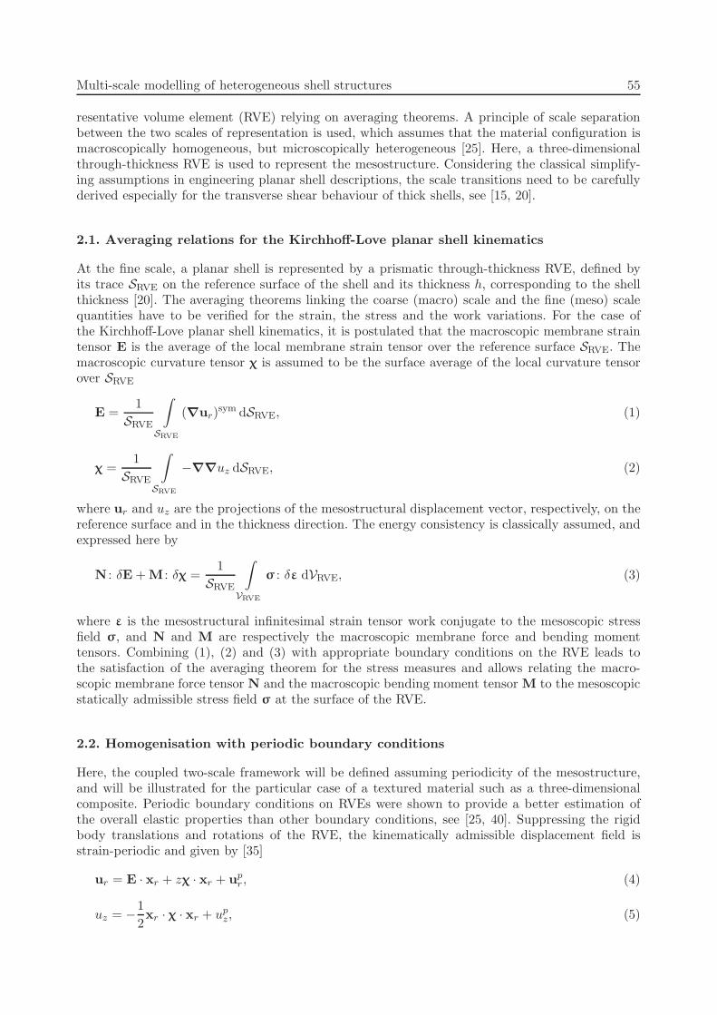
The proper size and geometry of a RVE should be deduced from statistical considerations [46],or defined by the periodicity of a given mesostructure. In the case of a small strain description,the Kirchhoff-Love generalised strains are given by six independent scalar quantities. The averagedeformed state of a RVE can therefore be fully prescribed using six displacements if periodicity isenforced. A possible choice for these six controlling displacements is given in Fig. 1, for the case ofwoven composites in which the periodic structure allows the use of perpendicular planar boundariesof a 3D through-thickness RVE.
Fig. 1. Control displacements system for a plain weave composite RVE.
The macroscopic membrane deformations are prescribed using three reference plane displace-ments, while the macroscopic curvatures are fixed by three out-of-plane displacements. UsingEqs. (1), (2), (4) and (5) as well as the periodicity conditions, the relations linking the controllingdisplacements to the average coarse-scale strains can be written as:
u11 = lE11, (6a)
u12 = lE12, (6b)
u22 = hE22, (6c)
u13 = −l2
2χ11, (6d)
u23 = −h2
2χ22, (6e)
u33 = −l2
2χ11 − hlχ12 −
h2
2χ22. (6f)
These relations can be recast in a matrix form reading:
{uctl} = [Du]−1{EKL}, (7)
where {uctl} is a column vector of the six controlling degrees of freedom, {EKL} is a columnvector of the Kirchhoff-Love generalised strains, and [Du] is a matrix which depends on the in-plane dimensions of the RVE. Similarly, considering (3), (4) and (5), the average Kirchhoff-Love

Multi-scale modelling of heterogeneous shell structures 57
stresses can be obtained from the controlling forces conjugated to the controlling displacements,and which represent the action of the neighbouring cells, see [32] for the detailed development. Forthe considered unit cell, these relations read:
N11 =1
hf11 , (8a)
N22 =1
lf22 , (8b)
N12 =1
2hf12 , (8c)
M11 = −l
2hf13 −
l
2hf33 , (8d)
M22 = −h
2lf23 −
h
2lf33 , (8e)
M12 = −1
2f33 . (8f)
In a matrix form, this can be written as:
{ΣKL} = [Df ]{fctl}, (9)
where {fctl} is a column vector of the six controlling forces, {ΣKL} is a column vector of theKirchhoff-Love generalised stresses, and [Df ] is a matrix which depends on the in-plane dimensionsof the RVE. Upon solving the RVE equilibrium boundary value problem for a given macroscopicgeneralised strain using a computational approach (finite element method), a mesostructural tan-gent stiffness [K] is readily available, linking variations of forces and displacements. This discretisedtangent stiffness relation of the RVE can be condensed on the controlling displacements, yielding{δfctl} = [K∗]{δuctl} where [K
∗] is the fine-scale (discrete) tangent stiffness matrix condensed atthe controlling degrees of freedom. Combining this condensed mesostructural tangent relation withvariations of (7) and (9) allows identifying the matrix relating variations of the generalised stresses{δΣKL} to those of the generalised strains {δEKL} as:
[L] = [Df ][K∗][Du]
−1, (10)
where [L] is nothing else than the matrix form of the homogenised membrane-flexural materialtangent stiffness defined as [32]
δN =4Lmm : δE +4
Lmf : δχ,
δM =4Lfm : δE +4
Lff : δχ.(11)
Note once again that these relations identifying the coarse-scale (macroscopic) material tangentstiffness are obtained computationally. The details of the fine-scale constitutive laws are implicitlyaccounted for in the condensed mesostructural tangent stiffness [K∗], and no closed-form relationbetween the fine-scale constitutive description and the tangents in (11) is required or available.
Based on Eq. (7), any average generalised deformation path can be prescribed. The relatedmesostructural boundary value problem is completely defined from the prescribed controlling de-grees of freedom and the periodicity boundary conditions, and can be solved using a classicalfinite element scheme, provided mesostructural constitutive laws are postulated. This type ofcontrol is classically used in multi-scale nested scheme using displacement-based finite elementschemes, [25, 30].

58 T.J. Massart, B.C.N. Mercatoris, B. Piezel, P. Berke, L. Laiarinandrasana, A. Thionnet
3. PLAIN WEAVE COMPOSITES RVE COMPUTATIONS
3.1. Study of plain weave composites unit cell
The previous homogenisation framework is now applied to a plain weave composite unit cell whichconsists in a single period RVE. The considered matrix is a polyvinyl chloride (PVC) matrix with athickness of 4 mm. The textile is composed of polyethylene terephthalate (PET) fibres for the warpyarns and polyamide 6-6 (PA66) fibres for the weft yarns. The repeating pattern is therefore thesimplest possible, and is represented in Fig. 2. Because of the complexity of the fabric pattern, themeshing tools developed in [28, 43] have been used. Conditions of periodicity are imposed on thedifferent faces of the cell in order to allow imposing the conditions (4) and (5). The meshing obtainedis then transferred toward ZeBuLoN FE code [9] developed by MINES ParisTech. Computationsare carried out with the ZeBuLoN code.
x
y
z
x
y
z
Fig. 2. Discretised periodic RVE for a plain weave composite (left) full RVE mesh with (right)reinforcement discretisation. The unit cell consists of a single period RVE.
At the macroscopic scale, due to the symmetries of its microstructure, the composite can beconsidered initially orthotropic. The mesoscopic scale allows taking the geometry of the fabric intoaccount. The focus here will be set on assessing the impact of changes at the mesoscopic scaleon the resulting macroscopic scale. While some contributions assess the out-of-plane loading ofplain weave textiles themselves [36], most of the recently available contributions related to themulti-scale analysis of complex textile reinforced composites, are focused on the in-plane responseof the material with periodic homogenisation [1] to extract average material properties. Recently,the local damage evolution under static tension for satin weave composites was analysed in [16].The case of laminates made of several plain weave layers subjected to in-plane tension was recentlyinvestigated in [22]. Specific boundary conditions on the RVE were defined to be applied on singlelayer RVEs to distinguish between the response of inner and outer layers, and avoiding periodicboundary conditions along the thickness. In the present contribution, a complementary approachis used were through-thickness RVEs will be used to allow assessing flexural loading effects.
3.2. Mesoscopic constitutive setting
The behaviour of the components (yarns and matrix) was reported elsewhere [38, 39]. The followingsimplifying assumptions are used. The behaviour of the matrix is assumed isotropic. The variationsof longitudinal yarns properties induced by their own strain are neglected [4, 19]. The non-linearbehaviour of the yarns can be identified by tensile tests as shown in [38, 39]. Three different domainscan be identified, namely an elastic domain, before a stiffening of the yarns, followed by the reductionof the tangent modulus and finally failure. These two last effects are not incorporated here. Theincrease of stiffness observed during the monotonous tensile tests was modelled with an elastoplasticbehaviour with two isotropic hardenings [8, 27]. The deformation is partitioned according to:
ǫ∼
= ǫ∼e
+ ǫ∼p
, (12)

Multi-scale modelling of heterogeneous shell structures 59
with ǫ∼e – the elastic part of the total strain and ǫ∼p – the plastic strain. The adopted yield function
reads
f(σ∼
, R) = J(σ∼
)−R, (13)
where J is the second invariant of the stress deviator defined by the equation:
J =
(
3
2sijsij
)1/2
, (14)
with s∼
the stress deviator. R is a scalar variable defining the isotropic hardening behaviour of thematerial. Its evolution laws reads:
R = R0 +Q(1− e−bp) +A(eBp − 1), (15)
with p – the cumulated plastic strain, and R0, Q, b, A and B material parameters to be determined.The increase of tangent modulus of the yarns with plastic strain is incorporated by the secondisotropic hardening terms of Eq. (15). The five parameters can be obtained by inverse methodsfrom the results of tensile tests carried out on the composite material as explained in [38]. Thesame parameters as in [38] are used for the sequel of this section and are reported in Table 1. Notethat the behaviour of the reinforcing material is approximated with an isotropic law. This mightinduce an overestimation of the transverse stiffness in the results.
Table 1. Material parameters for plain weave composite RVE computations:(a) matrix, (b) warp yarns, (c) weft yarns.
E ν R0 Q b A B
[MPa] [MPa] [MPa] [MPa]
(a) 400 0.3 – – – – –
(b) 15000 0.3 59 63 363 5.45 53.4
(c) 2996 0.3 5.6 15.34 403 7.4 68.9
3.3. Delamination stresses under flexural loading
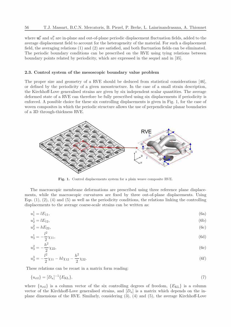
Based on relations (6) and (8), the average response of the composite shell can be deduced for anystrain or stress path. The effect of flexural loading on the potential delamination failure mechanismof textile reinforced composites will here be assessed assuming that the composite shell is used ina conveyor belt type application, see Fig. 3. To fix the imposed average deformations of the RVEswith realistic values, the composite shell will be subjected to an in-plane tension correspondingto the pre-tension present in a conveyor belt. In addition to this in-plane tension, the conveyorbelt is subjected to bending when passing on conveyor pulleys. Here, it is assumed that the pre-tension applied to such a conveyor belt is such that average longitudinal strain reaches a value ofELL = 0.0018. For the flexural effect, it is assumed that the belt is bent around the conveyor pulleywith a radius of 200 mm, which sets the imposed curvature on the RVE given its thickness. TheRVE computations presented below match these two imposed macroscopic strains. In the sequel,the case of a single plane weave unit cell is first considered, followed by the case of a stacking offour plane weave reinforced plies, as illustrated in Fig. 3.First an in-plane tension along the direction of the yarns is considered, in which the shell
homogenisation is used. Second, a combined tension-bending case is considered with the shellflexural homogenisation scheme to assess the potential influence of bending on delamination. Forboth cases, the focus is set on the stress state at the interface between the reinforcement and thematrix in order to assess the risk for delamination between both constituents. In order to comparethe different stress states at the interfaces between the reinforcement and the matrix, a simplifiedlocal stress criterion is adopted to assess potential delamination, defined as:
σdelamination =√
σ2nn + ατ2eq ≤ σmax,interface, (16)
60 T.J. Massart, B.C.N. Mercatoris, B. Piezel, P. Berke, L. Laiarinandrasana, A. Thionnet
x
y
z
xy
z
Fig. 3. Plain weave reinforced composites unit cells investigated: (left) loading scheme, (center) single layerRVE (the highlighted warp yarn will be the depicted in the stress maps), (right) RVE for stacking of four
plain weave plies.
where σnn is the stress component normal to the interface (peeling stress), τeq =√
τ2nt + τ2ns isthe tangential projection of the stress vector at the interface, and α is a coefficient accounting forthe relative contribution to failure of the interface of mode-I and mode-II stress components. Notethat only the distribution of the quantity defined by relation (16) will be analysed here, withoutexplicitly modelling the progressive degradation of the interface properties.
In-plane tension. As a first illustration, the results obtained for in-plane tension loading obtainedby the homogenisation are reported on Fig. 4. Figure 4 depicts the contributions of each stresscomponent present in (16) for the yarns in the warp direction (a single yarn is plotted to easeinterpretation due to the symmmetry of the two warp yarns in the cell). Under this pure tensioncase, the peeling stress σnn remains limited to 2.1 MPa. The delamination stress simplified criterion(16) reaches a value of 2.5 MPa. Clearly, such stress levels at the interface between the yarns andthe matrix are not suggesting potential delamination problems.
Fig. 4. Stress state at the warp yarns – matrix interface for in-plane tension along the warp direction: (left)normal (peeling) stress σnn, (right) delamination stress defined by (16) with α = 0.5. The colorbar is adapted
to ease the comparison with Fig. 5.
Tension-bending. Bending is next added to tension, assuming proportional loading for the sake
of simplicity. A curvature is added with the value χ =1
Rwith R the radius of the conveyor pulley
over which the belt is bent. Figure 5 depicts the various stress components entering relation (16).Due to the flexural effect captured by the shell scale transitions, the peeling stress σnn now reachesa maximal value of 6 MPa, while the tangential component reaches 8 MPa. The delamination stresscriterion (16) is now increased up to 8 MPa. These stress levels suggest that the incorporation ofthe flexural effect may, indeed, play a crucial role in a delamination process in such a conveyor belt.

Multi-scale modelling of heterogeneous shell structures 61
Fig. 5. Stress state at the warp yarns – matrix interface for in-plane tension along the warp direction combinedwith bending: (left) normal (peeling) stress σnn, (right) delamination stress defined by (16) with α = 0.5.
Stacked plain weave plies. Finally, the same tension-bending simulations are performed for a unitcell made of four stacked plain weave plies. Since the thickness of the shell increases, the bendingcomponent will generate higher strains in the outer layers of the shell when passing on to theconveyor pulley. For the same loading conditions (same in-plane deformation and same curvaturematching a conveyor pulley with a 200 mm radius), Fig. 6 depicts the stress state at the interfacebetween the warp yarns and the matrix for the outer ply. The peeling and the delamination stressesare as high as 30 MPa in this case, which clearly suggests that delamination should be a concern.
Fig. 6. Unit cell composed of four plain weave plies – Stress state at the warp yarns – matrix interface forin-plane tension along the warp direction combined with bending: (left) normal (peeling) stress σnn, (right)
delamination stress defined by (16) with α = 0.5.
4. LOCALISATION OF DAMAGE IN MASONRY SHELLS
4.1. Non-orthogonal periodic boundary conditions
As shown in [32, 35], the scale transition relationships (6) and (8) can be modified to account fornon orthogonal RVE boundaries, as for the specific stacking of constituents in masonry material, seeFig. 7. In such a case, relations (6) and (8) are modified to account for the periodicity parametersl, h and d as defined in [32]. The definitions of matrices in (7) and (9) are updated accordingly.
Fig. 7. Through-thickness RVE for running bond masonry [35].

62 T.J. Massart, B.C.N. Mercatoris, B. Piezel, P. Berke, L. Laiarinandrasana, A. Thionnet
4.2. Extraction of average localisation orientations
For the appearance of localisation at the structural scale, a criterion to detect localisation and itsorientation in shells is required, which should be based on the computational response of mesostruc-tural RVEs. Assuming a thin shell behaviour (no transverse shear effects) and an initially planarstructure, a criterion proposed in [29] is used, which was shown in [32] to properly detect localisa-tion in the context of two-scale computations. The procedure is based on the homogenised materialtangent stiffness governing the constitutive response (11), which can be deduced from the stiffnessof the RVE condensed at the controlling degrees of freedom by relation (10). The conditions forthe appearance of localisation in which material degradation occurs can be detected as a materialbifurcation. Across the interface between such a localising zone (l) and its surrounding material (s),the displacement and rotation fields can be assumed to be continuous and the generalised strainjumps have the form:
δE(l) − δE(s) =1
2(δmE n+ n δmE) ,
δχ(l) − δχ(s) =1
2(δmχn+ n δmχ) ,
(17)
where n is the normal to the localising zone, and mE and mχ are strain jumps, which vanishin the initial, homogeneous situation. These jumps must become nonzero for a localised state toexist. Using equilibrium, i.e., the continuity of the projected stress quantities at the interface of thelocalising zone:
n ·(
δN(l) − δN(s))
= 0,
n ·(
δM(l) − δM(s))
= 0
(18)
and by introducing Eqs. (11) and (17) in (18) with the classical linear comparison solid assumption(same material stiffness tangents on both sides of the localising zone interface), the stress continuityrequirement reads:[(
n · 4Lmm · n
) (
n · 4Lmf · n
)
(
n · 4Lfm · n
) (
n · 4Lff · n
)
]{
mE
mχ
}
= 0. (19)
This system of equations admits a non-trivial solution if
det (A(n)) = det
([(
n · 4Lmm · n
) (
n · 4Lmf · n
)
(
n · 4Lfm · n
) (
n · 4Lff · n
)
])
= 0 (20)
for some direction n, where A(n) is the acoustic tensor generalised to the Kirchhoff-Love shelltheory, see [29, 32]. A negative local maximum of the acoustic tensor determinant spectrum derivedfrom the homogenised material tangent stiffness was shown to match average orientations of coarse-scale localisation consistent with fine-scale damage patterns. This criterion can be used to determinean average localisation orientation in combination with the criterion for the loss of uniqueness ofthe discretised fine-scale boundary value problem, based on the nonpositive-definite character of itsdiscretised tangent stiffness [K∗] used to detect the onset of localisation [10]. As will be illustrated inSubsec. 4.4, it is crucial to use the complete generalised acoustic tensor defined in (20) including themembrane flexural couplings to properly detect multi-scale localisation for quasi-brittle materials.
4.3. Constitutive setting
A simplified fine-scale constitutive setting for masonry joints is used here (the bricks are assumedto be elastic). The behaviour of joints is modelled by initially elastic planar interface elements, for
Multi-scale modelling of heterogeneous shell structures 63
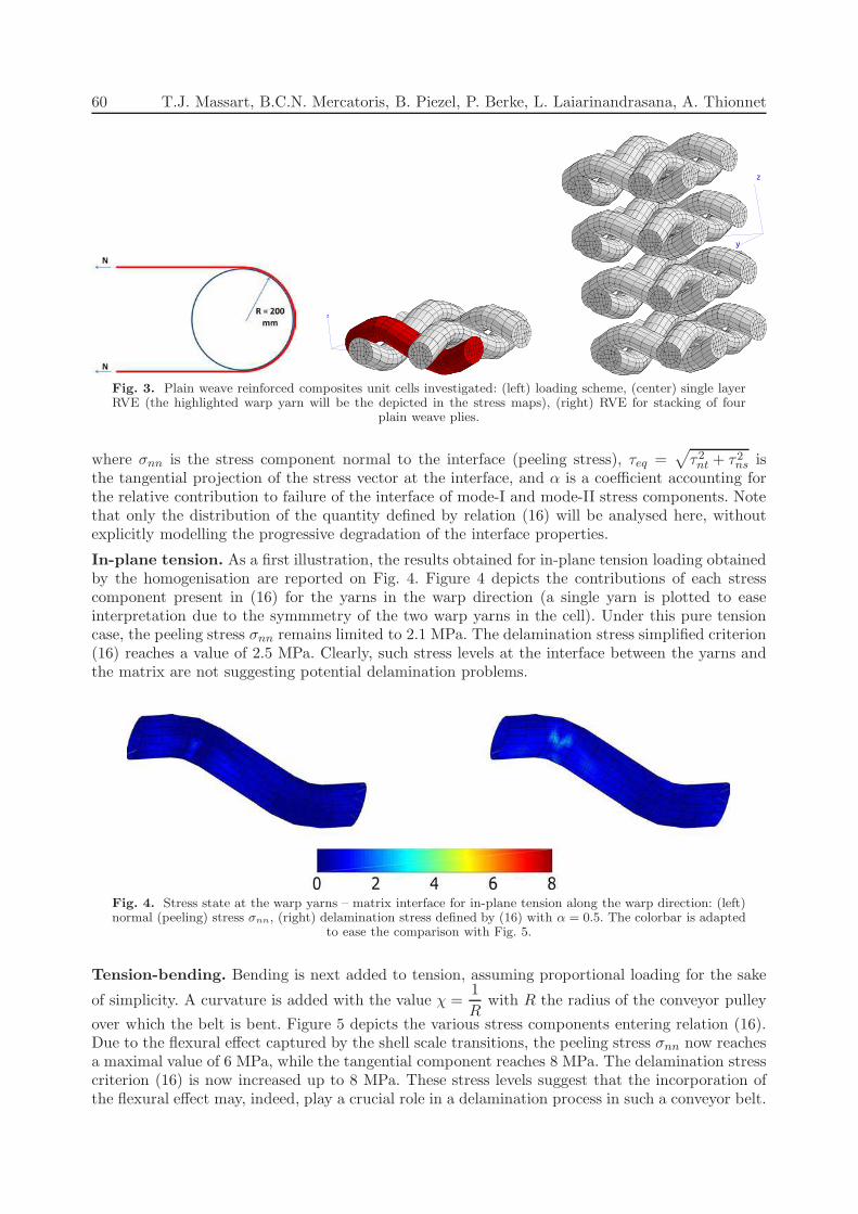
which both the normal and tangential stiffnesses (kn, kt, ks) can be related to the elastic behaviourof mortar. The tangential stiffnesses are assumed here to be equal (kt = ks). Depending on theloading mode, either a classical Mohr-Coulomb-type strength criterion or a tension cutoff is used,see Fig. 8. The parameter ft is the tensile mode I strength of the mortar or mortar-brick interfaces,while c is the cohesion and ϕ is the friction angle of the mortar joints. The compressive behaviourcan be considered, defined by a uniaxial compressive strength, and the angle of the compressive capwith respect to the σ axis. A scalar damage model with an exponential evolution law is considered.The traction-separation law, which links the traction vector t across the interface to the relativedisplacement vector δ, is given by
t = (1−D)H · δ, (21)
where D is the scalar damage variable growing from zero (virgin material) to one (complete failure)and H is a three-dimensional elastic stiffness (second order tensor) which depends on the elasticstiffnesses kn and kt. The damage evolution law of the mortar joint is given by
D(κ) = 1−ft
knκe−
ftGf
(
κ−ftkn
)
for κ ≥ft
kn, (22)
where Gf is the mode I tensile fracture energy. Since the considered interface is three-dimensionaland in order to take into account the different behaviours in tension and compression, the damage-driving parameter κ is taken as the most critical value of an equivalent relative displacementdefined by
δeq = max
ft
ctanϕδn +
ft
c
kt
kn
√
δ2s + δ2t
δn
−ft
fcδn +
ft
fc
kt
kn
1
tanϑ
√
δ2s + δ2t
. (23)
Fig. 8. Mohr-Coulomb criterion with tensile cutoff and compressive cap for the mortar joint/mortar-brickinterface.
4.4. Localisation analysis for RVE
In this Section, a localisation analysis is performed on a RVE in order to show how meaningfulaverage cracking orientations can be extracted from fine-scale computations. The unit cell repre-sented in Fig. 7 is considered with dimensions l = 200 mm, d = 100 mm, h = 80 mm, and witha thickness of 100 mm. The material parameters used in constituents (bricks and mortar joints)are given in Table 2. The cell is loaded with a bending momentMvv = 1500 kNm/m correspondingto an axis v at 50◦ from the vertical direction counterclockwise. This loading is expected to resultin a stair-case crack failure mode, the orientation of which can be deduced from geometrical argu-ments at −51.34◦. The response of the unit cell is depicted in Fig. 9, where the deformed state of
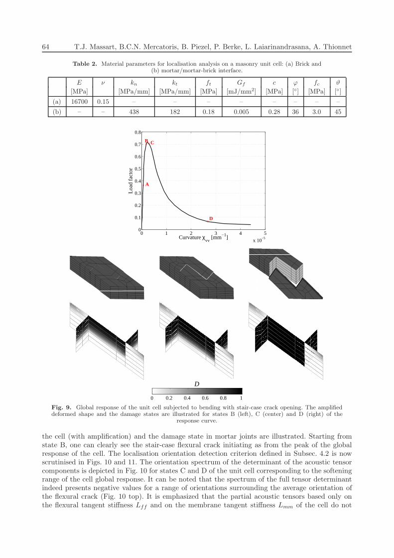
64 T.J. Massart, B.C.N. Mercatoris, B. Piezel, P. Berke, L. Laiarinandrasana, A. Thionnet
Table 2. Material parameters for localisation analysis on a masonry unit cell: (a) Brick and(b) mortar/mortar-brick interface.
E ν kn kt ft Gf c ϕ fc ϑ
[MPa] [MPa/mm] [MPa/mm] [MPa] [mJ/mm2] [MPa] [◦] [MPa] [◦]
(a) 16700 0.15 – – – – – – – –
(b) – – 438 182 0.18 0.005 0.28 36 3.0 45
0 1 2 3 4 5
x 10−5
0
0.1
0.2
0.3
0.4
0.5
0.6
0.7
0.8
A
B C
D
Load
fact
or
Curvature χvv
[mm−1]
D
0 0.2 0.4 0.6 0.8 1
Fig. 9. Global response of the unit cell subjected to bending with stair-case crack opening. The amplifieddeformed shape and the damage states are illustrated for states B (left), C (center) and D (right) of the
response curve.
the cell (with amplification) and the damage state in mortar joints are illustrated. Starting fromstate B, one can clearly see the stair-case flexural crack initiating as from the peak of the globalresponse of the cell. The localisation orientation detection criterion defined in Subsec. 4.2 is nowscrutinised in Figs. 10 and 11. The orientation spectrum of the determinant of the acoustic tensorcomponents is depicted in Fig. 10 for states C and D of the unit cell corresponding to the softeningrange of the cell global response. It can be noted that the spectrum of the full tensor determinantindeed presents negative values for a range of orientations surrounding the average orientation ofthe flexural crack (Fig. 10 top). It is emphasized that the partial acoustic tensors based only onthe flexural tangent stiffness Lff and on the membrane tangent stiffness Lmm of the cell do not
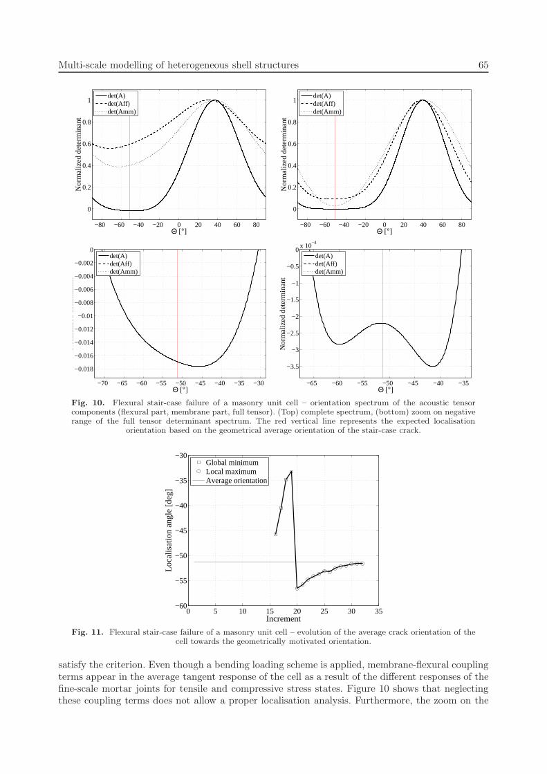
Multi-scale modelling of heterogeneous shell structures 65
−80 −60 −40 −20 0 20 40 60 80
0
0.2
0.4
0.6
0.8
1
Θ [°]
Nor
mal
ized
det
erm
inan
t
det(A)det(Aff)det(Amm)
−80 −60 −40 −20 0 20 40 60 80
0
0.2
0.4
0.6
0.8
1
Θ [°]
Nor
mal
ized
det
erm
inan
t
det(A)det(Aff)det(Amm)
−70 −65 −60 −55 −50 −45 −40 −35 −30
−0.018
−0.016
−0.014
−0.012
−0.01
−0.008
−0.006
−0.004
−0.002
0
Θ [°]
Nor
mal
ized
det
erm
inan
t
det(A)det(Aff)det(Amm)
−65 −60 −55 −50 −45 −40 −35
−3.5
−3
−2.5
−2
−1.5
−1
−0.5
0x 10
−4
Θ [°]
Nor
mal
ized
det
erm
inan
t
det(A)det(Aff)det(Amm)
Fig. 10. Flexural stair-case failure of a masonry unit cell – orientation spectrum of the acoustic tensorcomponents (flexural part, membrane part, full tensor). (Top) complete spectrum, (bottom) zoom on negativerange of the full tensor determinant spectrum. The red vertical line represents the expected localisation
orientation based on the geometrical average orientation of the stair-case crack.
0 5 10 15 20 25 30 35−60
−55
−50
−45
−40
−35
−30
Increment
Loca
lisat
ion
angl
e [d
eg]
Global minimumLocal maximumAverage orientation
Fig. 11. Flexural stair-case failure of a masonry unit cell – evolution of the average crack orientation of thecell towards the geometrically motivated orientation.
satisfy the criterion. Even though a bending loading scheme is applied, membrane-flexural couplingterms appear in the average tangent response of the cell as a result of the different responses of thefine-scale mortar joints for tensile and compressive stress states. Figure 10 shows that neglectingthese coupling terms does not allow a proper localisation analysis. Furthermore, the zoom on the

66 T.J. Massart, B.C.N. Mercatoris, B. Piezel, P. Berke, L. Laiarinandrasana, A. Thionnet
negative values of the full acoustic tensor determinant spectrum (bottom of Fig. 10) indicates thatan extremum is found converging towards the expected orientation, as damage progresses throughthe width of the joint. This confirms that the localisation criterion based on the average acoustictensor properly characterises the cracking orientation. The convergence of the extremum towardsthis orientation is illustrated in Fig. 11. As illustrated in Fig. 10, the precise orientation matchesa local maximum of the determinant in the negative range. Even though, there is no formal justifi-cation to select a precise orientation within the fan of negative values, this example suggests thatthis extremum should be selected in view of the damage maps presented in Fig. 9.
5. UP-SCALING OF FAILURE BEHAVIOUR
5.1. Homogenisation towards structural scale cohesive response
Based on the localisation detection presented above, it is possible to extract the information requiredto treat the global softening response in RVEs. The core ingredients were presented recently in [34]and are as follows. Before localisation, a FE2 type strategy is used in which the response of thequadrature points of the shell elements is computed as depicted in Fig. 12. At each convergedequilibrium configuration, each point of the structure is tested according to the localisation criteriondeveloped above. Based on the result of the localisation analysis, an embedded strong discontinuityis incorporated in the elements for which localisation was detected. This discontinuity introducesjumps in the deflection, the in-plane displacements, and the rotation fields, which are meant toaccount, in an average sense, for the fine-scale opening of mortar joints. From a finite elementinterpolation viewpoint, the formulation of such a discontinuity can be based on the developmentspresented in [3]. In contrast with [3], a closed form expression of the constitutive law governing thebehaviour of this discontinuity is here not available, due to the multi-scale nature of the framework.As a result, the behaviour of the softening discontinuity has to be obtained from RVE computationsbased on the updated scheme illustrated in Fig. 13. For each element in which a discontinuityis inserted, two different unit cells are considered. A first unit cell is used to characterise theresponse of the bulk of the finite element, which will be assumed in the sequel to unload alonga secant stiffness. A second, further damaging, unit cell is used to extract an equivalent traction-opening response of the discontinuity. Since the response of this further damaging unit cell refersto a finite volume of material characterised by a width wn, this quantity has to enter the scaletransition. The expressions relating the RVE quantities (curvatures, average strains, generalised
Fig. 12. FE2 computational scheme for shell structures.

Multi-scale modelling of heterogeneous shell structures 67
Fig. 13. Localisation-enhanced FE2 computational scheme for shell structures.
stress tensors, tangent stiffnesses) to corresponding discontinuity variables were recently developedin [34] based on an energy equivalence argument. These relations are illustrated in Fig. 13. Theidentified macroscopic equivalent responses of the bulk of the shell and of the discontinuity arecasted in a thin shell format (Kirchhoff-Love assumption). As a result, the scale transition doesnot furnish the information related to the shear behaviour. A Mindlin planar shell formulation ishowever used at the structural scale (DST – Discrete Shear Triangle), which requires a specifictreatment of transverse shear both for its interpolation (to avoid shear locking) and for the relatedmaterial behaviour. For full details concerning these aspects, the reader is referred to [34].
5.2. Anisotropic flexural response of masonry wallets
The proposed localisation enhanced FE2 framework is used here to analyse the structural response ofa masonry panel loaded perpendicular to its plane as illustrated in Fig. 14. The structure consists ina three point bending test on a panel which is supported on its two shortest sides. The orientation ofthe masonry material symmetry axes is chosen in a non-standard way such that the stair-case crackorientation is aligned with the supported sides. The wall size is 1200 mm × 600 mm with a thicknessof 53 mm, while the unit cell dimensions are chosen as l = 88 mm with d = h = 44 mm. The
Fig. 14. Problem set-up for the masonry wallet structural computation. Structural finite element discretisationwith imperfection (in red – left), (right) orientation of joints with respect to the overall structure.

68 T.J. Massart, B.C.N. Mercatoris, B. Piezel, P. Berke, L. Laiarinandrasana, A. Thionnet
material parameters used at the fine scale considered in this computation are reported in Table 3.These values correspond to a fine-scale description in which only the Mohr-Coulomb failure criterionis active. In order to show the ability of the framework to properly describe crack propagation, aninitial imperfection is assumed in the wallet in a zone corresponding to two elements. In thisimperfect zone, the tensile strength, the cohesion and the fracture energy of joints are all decreasedby a factor 2. The results of the test are depicted in Figs. 15 to 17. As depicted in Fig. 15, theresponse of the structure can be traced until far in the post-peak regime (the computation isperformed under displacement control). Cracking initiates in the weakened zone. The peak load
Table 3. Material parameters for FE2 computation on masonry wallet: (a) Brick and(b) mortar/mortar-brick interface.
E ν kn kt ft Gf c ϕ fc ϑ
[MPa] [MPa/mm] [MPa/mm] [MPa] [mJ/mm2] [MPa] [◦] [MPa] [◦]
(a) 16700 0.15 – – – – – – – –
(b) – – 438 182 0.38 0.02 0.28 36 ∞ 80
0 0.2 0.4 0.6 0.8 10
100
200
300
400
500
600
700
800
A
B
C
Deflection [mm]
Load
[N]
Fig. 15. Structural response of the masonry panel with deformed configuration at different stages of thecracking process.
Fig. 16. Deformed configuration and damage maps of the masonry panel at stage B.

Multi-scale modelling of heterogeneous shell structures 69
Fig. 17. Deformed configuration and damage maps of the masonry panel at stage C.
is obtained when the localising discontinuity propagation reaches half of the structure width. Atthe peak load, it can be seen in the cell states depicted in Fig. 16 that the flexural stair-casedamage pattern is well developed, even in at the position where structural scale localisation is notreached yet (point (3)). The damage pattern is however more developed across the thickness inthe first cracking elements (point (1)). Since the crack is not fully propagated to the completewidth of the structure, the deformed configuration of the structure at the peak load still exhibitsa more or less distributed curvature. On the contrary, at the end of the structural softening tail(point C – Fig. 17), the stair-case crack pattern is fully developed in the unit cells across thecomplete structure. Figure 17 clearly shows a localised curvature at the structural scale due to thediscontinuities, with unloaded portions of the wallet.
6. CONCLUSIONS
A shell-oriented computational homogenisation framework was presented and applied to practicalsituations. Based on a generalisation of periodic homogenisation, scale transitions were presentedwhich allow using through-thickness 3D RVEs to extract the average response of heterogeneousshells with complex microstructures. These scale transitions were applied to two types of materials,showing that flexural effects cannot be neglected in practical applications. First, the effect of bend-ing terms in the homogenisation of textile reinforced composites was assessed by means of RVEcomputations. The shell homogenisation framework allowed to illustrate the importance of flexuraleffects on the potential delamination failure mode of single ply conveyor belts. Another examplefeaturing a four ply RVE showed that this effect is even more important in that case. Second, thecomputational homogenisation framework was used in combination with a macroscopic localisationdetection for masonry cracking. The importance of incorporating membrane-flexural couplings inthe detection of structural localisation for quasi-brittle materials was underlined by means of anRVE computation example. The incorporation of macroscopic localisation of degradation in FE2
computational schemes was discussed and illustrated on a masonry wallet computation. Futuredevelopments of the presented framework are related to the simulation of delamination in textilereinforced composites.
ACKNOWLEDGEMENTS
The authors gratefully acknowledge the support of F.R.S.-FNRS for intensive computation facilities.The second and fourth authors are supported as F.R.S.-FNRS post-doctoral researcher. The firstand third authors are supported in the frame of a scientific impulsion grant.
70 T.J. Massart, B.C.N. Mercatoris, B. Piezel, P. Berke, L. Laiarinandrasana, A. Thionnet
REFERENCES
[1] S.L. Angioni, M. Meoa, A. Foreman. A comparison of homogenization methods for 2-D woven compositesComposites: Part B, 42: 181–189, 2011.
[2] M. Ansar, W. Xinwei, Z. Chouwei. Modeling strategies of 3D woven composites: A review Composite Structures,93: 1947–1963, 2011.
[3] F. Armero and D. Ehrlich. Finite element methods for the multi-scale modeling of softening hinge lines in platesat failure. Computer Methods in Applied Mechanics and Engineering, 195(13–16): 1283–1324, 2006.
[4] P. Badel, E. Vidal-Salle, E. Maire, and P. Boisse. Simulation and tomography analysis of textile compositereinforcement deformation at the mesoscopic scale. Composites Science and Technology, 68: 2433–2440, 2008.
[5] T. Belytschko, S. Loehnert, and J.H. Song. Multiscale aggregating discontinuities: A method for circumventingloss of material stability. International Journal for Numerical Methods in Engineering, 73(6): 869–894, 2008.
[6] T. Belytschko and J.H. Song. Coarse-graining of multiscale crack propagation. International Journal for Nu-merical Methods in Engineering, 81: 537–563, 2010.
[7] A. Bensoussan, J.L. Lions, and G. Papanicolaou. Asymptotic analysis for periodic structures. North-HollandPublishing Company, 1978.
[8] J. Besson, G. Cailletaud, J.L. Chaboche and S. Forest Mecanique non lineaire des materiaux, Hermes, 2001.
[9] J. Besson and R. Foerch. Large scale object oriented finite element code design. Computer Methods in AppliedMechanics and Engineering, 142: 165–187, 1997.
[10] R. de Borst, L.J. Sluys, H.B. Muhlhaus, and J. Pamin. Fundamental issues in finite element analyses of local-ization of deformation. Engineering Computations, 10(2): 99–121, 1993.
[11] S. Brasile, R. Casciaro, and G. Formica. Multilevel approach for brick masonry walls – Part I: A numericalstrategy for the nonlinear analysis. Computer Methods in Applied Mechanics and Engineering, 196: 4934–4951,2007.
[12] P. Cartraud and T. Messager. Computational homogenization of periodic beam-like structures. InternationalJournal of Solids and Structures, 43(3–4): 686–696, 2006.
[13] A. Cecchi and K. Sab. A homogenized Reissner-Mindlin model for orthotropic periodic plates: Application tobrickwork panels. International Journal of Solids and Structures, 44(18–19): 6055–6079, 2007.
[14] K.S. Challagulla, A. Georgiades, G.C. Saha, and A.L. Kalamkarov. Micromechanical analysis of grid-reinforcedthin composite generally orthotropic shells. Composites Part B-Engineering, 39(4): 627–644, 2008.
[15] E.W.C. Coenen, V.G. Kouznetsova, and M.G.D. Geers. Computational homogenization for heterogeneous thinsheets. International Journal for Numerical Methods in Engineering, 83(8–9): 1180–1205, 2010.
[16] S. Daggumati, W. Van Paepegem, J. Degrieck, J. Xu, S.V. Lomov, I. Verpoest. Local damage in a 5-harnesssatin weave composite under static tension: Part II – Meso-FE modelling. Composites Science and Technology,70: 1934–1941, 2010.
[17] V.S. Deshpande, N.A. Fleck. Collapse of truss core sandwich beams in 3-point bending. International Journalof Solids and Structures, 38: 6275–6305, 2001.
[18] F. Feyel and J.L. Chaboche. FE2 multiscale approach for modelling the elastoviscoplastic behaviour of long fiberSiC/Ti composite materials. Computer Methods in Applied Mechanics and Engineering, 183(3–4): 309–330,2000.
[19] A. Gasser, P. Boisse and S. Hanklar. Mechanical behaviour of dry fabric reinforcements. 3D simulations versusbiaxial tests. Computational Materials Science. 17: 7–20, 2000
[20] M.G.D. Geers, E.W.C. Coenen, and V.G. Kouznetsova. Multi-scale computational homogenization of structuredthin sheets. Modelling and Simulation in Materials Science and Engineering, 15(4): S393–S404, 2007.
[21] A. Ibrahimbegovic and D. Markovic. Strong coupling methods in multi-phase and multi-scale modeling of inelas-tic behavior of heterogeneous structures. Computer Methods in Applied Mechanics and Engineering, 192(28–30):3089–3107, 2003.
[22] D.S. Ivanov, S.V. Lomov, S.G. Ivanov, I. Verpoest. Stress distribution in outer and inner plies of textile laminatesand novel boundary conditions for unit cell analysis. Composites: Part A, 41: 571–580, 2010.
[23] H.E. Johnson, L.A. Louca, S. Mouring, A.S. Fallah. Modelling impact damage in marine composite panelsInternational Journal of Impact Engineering, 36: 25–39, 2009.
[24] A.L. Kalamkarov, I.V. Andrianov, and V.V. Danishevs’kyy. Asymptotic homogenization of composite materialsand structures. Applied Mechanics Reviews, 62(3), 2009. Article Number: 030802.
[25] V.G. Kouznetsova, W.A.M. Brekelmans, and F.P.T. Baaijens. An approach to micro-macro modeling of hetero-geneous materials. Computational Mechanics, 27(1): 37–48, 2001.
[26] V.G. Kouznetsova, M.G.D. Geers, and W.A.M. Brekelmans. Multi-scale second-order computational homog-enization of multi-phase materials: a nested finite element solution strategy. Computer Methods in AppliedMechanics and Engineering, 193(48–51): 5525–5550, 2004.
[27] J. Lemaitre, J.L. Chaboche Mecanique des materiaux solides, Dunod, 1985.[28] S.V. Lomov et al. Meso-FE modelling of textile composites : Road map, data flow and algorithms. CompositesScience and Technology, 67: 1870–1891, 2007.
Multi-scale modelling of heterogeneous shell structures 71
[29] J. Makowski and H. Stumpf. Strain localization in stress-resultant theory of shells. Mechanics Research Com-munications, 25(4): 455–465, 1998.
[30] T.J. Massart, R.H.J. Peerlings, and M.G.D. Geers. An enhanced multi-scale approach for masonry wall com-putations with localization of damage. International Journal for Numerical Methods in Engineering, 69(5):1022–1059, 2007.
[31] T.J. Massart, R.H.J. Peerlings, and M.G.D. Geers Structural damage analysis of masonry walls using computa-tional homogenization International Journal of Damage Mechanics, 16: 199–226, 2007.
[32] B.C.N. Mercatoris, P. Bouillard, and T.J. Massart. Multi-scale detection of failure in planar masonry thin shellsusing computational homogenisation. Engineering Fracture Mechanics, 76(4): 479–499, 2009.
[33] B.C.N. Mercatoris and T.J. Massart. Assessment of periodic homogenization-based multiscale computationalschemes for quasi-brittle structural failure. International Journal for Multiscale Computational Engineering,7(2): 153–170, 2009.
[34] B.C.N. Mercatoris and T.J. Massart. A coupled two-scale computational scheme for the failure of periodicquasi-brittle thin planar shells and its application to masonry. International Journal For Numerical Methods inEngineering, 85: 1177–1206, 2011.
[35] M. Mistler, A. Anthoine, and C. Butenweg. In-plane and out-of-plane homogenisation of masonry. Computers& Structures, 85(17–18): 1321–1330, 2007.
[36] G. Nilakantan, M. Keefe, T.A. Bogetti, R. Adkinson, J.W. Gillespie. On the finite element analysis of wovenfabric impact using multiscale modeling techniques International Journal of Solids and Structures, 47: 2300–2315, 2010.
[37] R.H.J. Peerlings and N.A. Fleck. Computational evaluation of strain gradient elasticity constants. InternationalJournal for Multiscale Computational Engineering, 2(4): 599–619, 2004.
[38] B. Piezel. Comportement et analyse multi-echelles d’un composite a renfort tisse tridimensionnel. PhD Thesis,Mines ParisTech, France, 2010.
[39] B. Piezel, L. Laiarinandrasana, E. Mansour, J. Renard, and A. Thionnet. Analyse experimentale d’un compositetextile en vue d’une modelisation multi-echelles. 16e Journees Nationale sur les Composites – JNC 16, France,2009.
[40] R.J.M. Smit, W.A.M. Brekelmans, and H.E.H. Meijer. Prediction of the mechanical behavior of nonlinear het-erogeneous systems by multi-level finite element modeling. Computer Methods in Applied Mechanics and Engi-neering, 155(1–2): 181–192, 1998.
[41] P. Suquet. Elements of homogenization for inelastic solid mechanics. In: Homogenization techniques for compositemedia., volume 272. Springer-Verlag, Berlin, 1987.
[42] K.I. Tserpes, G. Labeas, S. Pantelakis. Multi-scale modeling of the mechanical response of plain weave compositesand cellular solids Theoretical and Applied Fracture Mechanics, 54: 172–179, 2010.
[43] I. Verpoest and S.V. Lomov. Virtual textile composites software WiseTex : Integration with micro-mechanical,permeability and structural analysis. Composites Science and Technology, 65: 2563–2574, 2005.
[44] P.N. Vinh, O. Lloberas-Valls, M. Stroeven, L.J. Sluys. Homogenization-based multiscale crack modelling: Frommicro-diffusive damage to macro-cracks Computer Methods in Applied Mechanics and Engineering, 200(9–12):1220–1236, 2011.
[45] H.N.G. Wadley, N.A. Fleck, A.G. Evans. Fabrication and structural performance of periodic cellular metalsandwich structures. Composites Science and Technology, 63: 2331–2343, 2003.
[46] J. Zeman and M. Sejnoha. From random microstructures to representative volume elements. Modelling andSimulation in Materials Science and Engineering, 15(4): S325–S335, 2007.