multi response optimisation of die sinker...
TRANSCRIPT

http://www.iaeme.com/IJMET/index.asp 63 [email protected]
International Journal of Mechanical Engineering and Technology (IJMET)
Volume 7, Issue 3, May–June 2016, pp.63–77, Article ID: IJMET_07_03_006
Available online at
http://www.iaeme.com/IJMET/issues.asp?JType=IJMET&VType=7&IType=3
Journal Impact Factor (2016): 9.2286 (Calculated by GISI) www.jifactor.com
ISSN Print: 0976-6340 and ISSN Online: 0976-6359
© IAEME Publication
MULTI RESPONSE OPTIMISATION OF DIE
SINKER EDM FOR ALSIC COMPOSITE
Mukesh Regmi
Asst. Professor, Nepal College of Information Technology, Kathmandu
Anil Pol
Asst. Professor, Department of PG Studies, VTU, Belgaum
Sachin Kulkarni
Asst. Professor, Gogte Institute of Technology, Belgaum
ABSTRACT
One of the important aspects that should be taken into consideration in the
majority of manufacturing processes and, particularly, in processes related to
Electrical Discharge Machining (EDM) is the correct selection of
manufacturing conditions. Appropriate choice of the machining parameters
and electrode material during electric discharge machining is fundamental to
its performance and accuracy.
This paper presents a fundamental study of EDM by using two different
electrode and aims at investigating the effect of EDM parameters on material
removal rate (MRR) and tool wear rate (TWR) as an alternative method for
machining Aluminium Silicon Carbide (AlSiC ) metal matrix composite
produced with stir casting method. The primary aim of this research is to
determine the optimal machining parameter conditions of intensity of current,
pulse on time and pulse off time and proper electrode material for machining
AlSiC workpiece using EDM.
The concept of response surface methodology, with a well-designed
experimental scheme named central composite design was used and a second
order model capable of predicting the responses is developed. This model was
further checked for its adequacy by using ANOVA analysis and the results was
further validated by the justification from the related literature.
Key words: EDM (Electric Discharge Machining), AlSiC MMC (Aluminium
Silicon Carbide Metal Matrix Composite), MRR(Material Removal Rate),
TWR(Tool Wear Rate), ANOVA(Analysis of Variance), RSM(Response
Surface Methodology)
Mukesh Regmi, Anil Pol and Sachin Kulkarni
http://www.iaeme.com/IJMET/index.asp 64 [email protected]
Cite this Article Mukesh Regmi, Anil Pol, Sachin Kulkarni, Multi Response
Optimisation of Die Sinker EDM for Alsic Composite. International Journal
of Mechanical Engineering and Technology, 7(3), 2016, pp. 63–77.
http://www.iaeme.com/currentissue.asp?JType=IJMET&VType=7&IType=3
1. INTRODUCTION
Parts manufactured by casting, forming, and various shaping processes often require
further operations before they are ready for use or assembly. So a proper machining
need to be done which involves the removal of some material from the work piece
(machining allowance) in order to produce a specific geometry at a certain degree of
accuracy and surface quality in a cheap cost.
In modern machining practice, harder, stronger, and tougher materials that are
more difficult to cut are frequently used. More attention is, therefore, directed toward
machining processes where the mechanical properties of the work piece material are
not imposing any limits on the material removal process. In this regard, the
nonconventional machining techniques like Electric Discharge Machining (EDM)
came into practice [1].
Electric Discharge Machining (EDM), sometimes colloquially also referred to
as spark machining, spark eroding, burning, die sinking or wire erosion, is an electro-
thermal non-traditional machining process, where electrical energy is used to generate
electrical spark and material removal mainly occurs due to thermal energy of the
spark. Material is removed from the work piece by a series of rapidly recurring
current discharges between two electrodes which are separated by
a dielectric liquid and subject to an electric voltage.
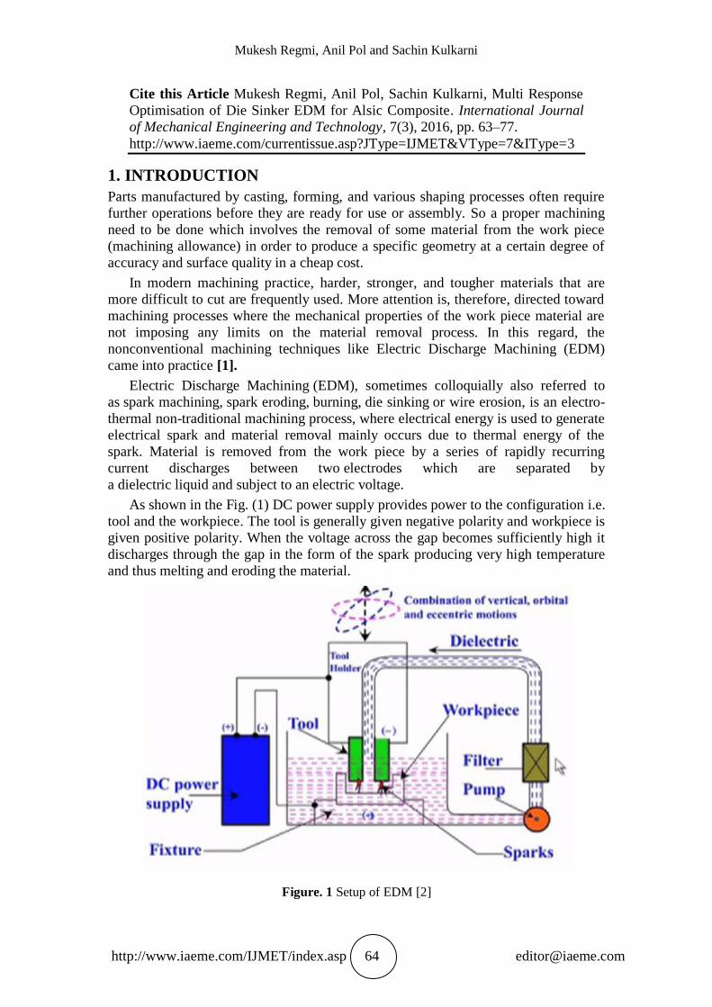
As shown in the Fig. (1) DC power supply provides power to the configuration i.e.
tool and the workpiece. The tool is generally given negative polarity and workpiece is
given positive polarity. When the voltage across the gap becomes sufficiently high it
discharges through the gap in the form of the spark producing very high temperature
and thus melting and eroding the material.
Figure. 1 Setup of EDM [2]

Multi Response Optimisation of Die Sinker EDM for Alsic Composite
http://www.iaeme.com/IJMET/index.asp 65 [email protected]
2. LITERATURE REVIEW
P. Janmanee et al. [3] evaluated the performance of different electrode materials like
graphite, copper-graphite and copper-tungsten in EDM of tungsten carbide. The
important parameters were discharge current, pulse on time, pulse off time, open-
circuit voltage and electrode polarity. Their investigation concluded that MRR
increases with the discharge current intensity and graphite electrode gives the most
MRR but it gives high electrode wear ratio.
B.Mohan et al. [4] had studied EDM of AlSiC composites with 20-25 vol. % SiC
taking the following like Current, electrode material polarity, pulse duration and
rotation of electrode on MRR, TWR, and SR. It was observed that the increase in
volume percentage of SiC has resulted in decrease in MRR, SR and increase in EWR
and the increase in rotational speed of the tube electrode has produced higher MRR,
EWR and better SR.
Harish K.Garg et al. [5] studied about the machining of the hybrid Aluminium Metal
Matrix composite (Al/SiC/Gr and Al/Si10Mg/Fly ash/Gr). They investigated about
the problems encountered during machining of hybrid MMCs and concluded that
machining of Al/SiC-MMC is one of the major problem, which resist its wide
spread application in industry and the problems faced were rapid TWR, irregular
MRR, requirement of large pulse current values, difficult to cut very complex and
complicated shape or geometrical profile etc.
S.L.Chen et al. [6] studied about various parameters of EDM like electrode material,
pulse duration, discharge current and polarity using two materials namely silicon
carbide and tungsten carbide as work piece and copper and copper tungsten as a tool
material. They concluded that MRR is directly proportional to current and pulse
duration, Electrode wear increased up to 80 µs then started decreasing with increase
in pulse duration. They came into conclusion that Copper is better than copper
tungsten as an electrode material due to homogeneous wear ratio.
2.1. Objective of the Present Work
The objective of the present work is an attempt to finding feasibility of machining
Al/SiC composite material using brass as well as copper tungsten electrode. In
summary the objective of the project is;-
Selection of process variables such as Intensity of current, Pulse on time & Pulse off
time in Die-Sink-EDM for machining of Al/SiC Metal Matrix Composite.
To investigate the Effect of different tool Electrodes such as brass & CuW on MRR
and TWR
To develop an empirical model for Intensity of current, Pulse on time & Pulse off
time for machining of Al/Sic Metal Matrix Composite using RSM.
To verify the lack of fit of the proposed model using analysis of variance
(ANOVA).
3. MATERIALS AND METHODOLOGY
a) Tool material
In this experiment brass and copper tungsten both having 7mm.machining diameter
was used as a tool electrode. The important factors in selecting brass and cooper
tungsten are their high strength-to-weight ratio, resistance to corrosion by many
chemicals, high thermal and electrical conductivity, non-toxicity, reflectivity,
appearance and ease of formability and of machinability; they are also nonmagnetic.
Mukesh Regmi, Anil Pol and Sachin Kulkarni
http://www.iaeme.com/IJMET/index.asp 66 [email protected]
b) Workpiece material
The workpiece material chosen was aluminium silicon carbide (AlSiC) metal matrix
composite produced with stir casting method consisting of aluminum matrix with 3%
silicon carbide particles. It has high thermal conductivity (180–200 W/m K), and
its thermal expansion can be adjusted to match other materials,
e.g. silicon and gallium arsenide chips and various ceramics. It is chiefly used
in microelectronics as substrate for power semiconductor devices and high
density multi-chip modules, where it aids with removal of waste heat.
c) Response Surface Methodology
Response surface methodology (RSM) is a collection of mathematical and statistical
techniques that are useful for modeling and analysis of problems in which output or
response is influenced by several variables and the goal of RSM is to find the
correlation between the response and the variables. It is used in the development of an
adequate functional relationship between a response of interest, y, and a number of
associated control (or input) variables denoted by x1, x2, xk.
Suppose X1 and X2 are the factors or parameters of interest of the process and ‘Yi’
is the maximum yield of the process then the yield is a function of levels of X1 and X2
i.e.
Yi= f (X1, X2) + ei (1)
where ‘ei’ represents the noise or error observed in the response Yi. If we denote
the expected response by
E (Yi) = f (X1, X2) = η (2)
Then the surface represented by
η = f (X1, X2) (3)
is called response surface.
If there is curvature in the system, then a polynomial of higher degree must be
used, such as the second-order model given in equation 4
(4)
Central composite design is an experimental design, useful in response surface
methodology, for building a second order (quadratic) model for the response variable
without needing to use a complete three-level factorial experiment.[7] The CCD used
in our experiment is shown below-
Table 1 Design Insight
Design Central Composite Design
Factors 3 Replicates 1 Total runs 20
Base blocks 1 Base runs 20 Total
blocks
1
Cube points 8 Center points in cube 6 Axial
Points
6
Multi Response Optimisation of Die Sinker EDM for Alsic Composite
http://www.iaeme.com/IJMET/index.asp 67 [email protected]
d) Design Matrix
In this study, three machining parameters were selected as control factors and each
parameter was designed to have three levels denoted by 1, 2 and 3 respectively. The
experiments are planned using CCD in the design of experiments (DOE), which helps
in reducing the number of experiments. The total 20 experimental runs were
conducted with each tool on the workpiece and results of MRR and TWR was
calculated. The process variables with their units and notations are shown in the Table
1 below-
Table 2 Parameters and Levels
MACHINING
PARAMETER
UNIT
RANGE AND LEVELS
-1 0 +1
Pulse on time µs 20 40 60
Pulse off time µs 2 5 8
Current A 4 6 8
e) Macine used
The experimentation was conducted using EDM, model SAVITA 4631l (Die sinking
type) having following specifications-
Table 3 Machine Specifications
S.N. TYPES Unit 46311
1 Work tank dimensions mm3
600*370*250
2 Table size mm2
350*200
3 X-Axis Travel mm 200
4 Y-Axis Travel mm 120
5 Z-Axis Travel mm 150
6 Maximum Job Height mm 140
7 Maximum Electrode Weight kg 50
8 Maximum Job Weight kg. 150
9 Dielectric Tank Capacity Lt. 100
10 Machine Weight kg 450
11 Gross weight kg 600
12 Day Light mm 410
13 Throat mm 250
14 Overall Dimensions m3
0.8*0.8*1.8

Mukesh Regmi, Anil Pol and Sachin Kulkarni
http://www.iaeme.com/IJMET/index.asp 68 [email protected]
4. EXPERIMENTATION
a) Experimental Procedure
Experiment was conducted with negative polarity of electrode. The electrode brass
was taken. The diameter of electrode is measured with a micrometer. It was made
sure its dimension is according to specification.
An initial mass is measured with precision balance. The electrode mass value and the
work piece mass value were jotted.
The work material (Aluminium Silicon Carbide) was mounted on the T-slot table and
positioned at the desired place and clamped. The electrode was clamped on the tool
holder, and its alignment was checked.
The parameters of the experiment were set regarding Table (3.1) and Table (3.2).
The time was set as 2 minutes for the machining of all work materials. Finally,
switches ‘ON’ for operating the desire discharge current values.
After machining operation, the electrode was taken out and weighed again on
weighing balance. Also the mass value of work piece was taken after machining.
The same experiment was repeated with copper tungsten electrode. This experiment
is done 20 times for each electrode. The data was fed to the MINITAB where
calculation and analysis of results is done.
b) MRR and TWR Evaluation
The material MRR has been calculated by taking the difference between the weight of
the work piece before and after machining to the machining time.
MRR=
(1)
Where,
Wb = Weight of work piece before machining in gm
Wa = Weight of work piece after machining in gm
t = Machining time in minutes
TWR is calculated in the same fashion by taking the difference of weight of
the tool before and after machining to the machining time.
TWR=
(1.2)
Where,
Wbt = Weight of the tool before machining in gm.
Wat = Weight of the tool after machining in gm.
t = Machining time in minutes

Multi Response Optimisation of Die Sinker EDM for Alsic Composite
http://www.iaeme.com/IJMET/index.asp 69 [email protected]
Figure. 2 MRR with CuW Versus Brass
Figure 3 TWR with CuW Versus Brass
The MRR and TWR values were calculated for both the copper tungsten and brass
tool experimental run and then plotted on the graph with their corresponding values.
5. RESULTS AND DISCUSSION
For interpreting the significant effect of the parameters, a statistical software program
called MINITAB version 16 has been used. The experimental results from the tables
were analyzed using ANOVA, which is used for identifying the factors significantly
affecting the performance measures. The analysis was carried out for the significance
level of α=0.1 i.e. for a confidence level of 90%. The sources with the p value less
than 0.1are considered to have a statistically significant.
0
0.05
0.1
0.15
0.2
0.25
0.3
1 2 3 4 5 6 7 8 9 10 11 12 13 14 15 16 17 18 19 20
MRR with CuW Versus Brass
MRR with CuW MRR with Brass
0
0.01
0.02
0.03
0.04
0.05
0.06
0.07
0.08
1 2 3 4 5 6 7 8 9 10 11 12 13 14 15 16 17 18 19 20
TWR with CuW Versus Brass
TWR with CuW TWR with Brass

Mukesh Regmi, Anil Pol and Sachin Kulkarni
http://www.iaeme.com/IJMET/index.asp 70 [email protected]
Results for MRR with CuW Versus Brass
Figure. (2) shows the MRR for both the electrodes where it has been conspicuous that
CuW gives more MRR than brass for the same machining conditions.
Results for TWR with CuW Versus Brass
Figure (3) shows the TWR for both the electrodes where it has been clearly seen that
Brass has far higher tool wear than that of CuW.
Results of MRR with CuW
Table 4 Estimated Regression Coefficients for MRR
Terms Coeff. SE Coeff. T test P value
C -0.276914 0.102577 -2.700 0.022 *
I 0.037469 0.036520 1.026 0.329
Ton 0.007907 0.002650 2.984 0.014 *
Toff 0.032999 0.015603 2.115 0.061 *
I* I -0.001465 0.002939 -0.499 0.629
Ton *Ton -0.000076 0.000029 -2.600 0.027 *
Toff *Toff -0.001665 0.001306 -1.275 0.231
I*Ton 0.000081 0.000172 0.472 0.647
I*Toff -0.000098 0.001149 -0.085 0.934
Ton*Toff -0.000233 0.000115 -2.029 0.070 *
S = 0.0194943, R-Sq = 91.55%, R-Sq(pred) = 19.63% , R-Sq(adj) = 83.95%
From the ANOVA table, the main effects of pulse on time and pulse off time can
be deduced as having significant effect. Thus, the final model correlating Material
Removal Rate with cutting parameters is found as follows:
The effectiveness of the model is checked by using the ‘R2’ value i.e. 0.91 which
is very close to 1 and hence the model is found to be very effective. The validity of
the model is reconsidered with the adjusted correlation coefficient i.e. ‘R2
(adj.)’value
= 0.83, which is a measure of the variability of the observed output and can be
explained by the factors along their factor interactions.

Multi Response Optimisation of Die Sinker EDM for Alsic Composite
http://www.iaeme.com/IJMET/index.asp 71 [email protected]
864
0.18
0.16
0.14
0.12
0.10
604020
852
0.18
0.16
0.14
0.12
0.10
Current
Me
an
Pulse on time
Pulse off time
Main Effects Plot for MRRData Means
Figure. 4 Main Effect for MRR with CuW tool
The graph shows that increase in the value of current leads to the significant
increase in MRR. This increase of MRR with current is due to the fact that with the
increase in amount of pulse current generates strong spark which creates higher
temperature, due to which more material is melted and eroded from the workpiece [8].
The graph reveals that on increasing the pulse on time, MRR goes on increasing
up to half the way and it goes on decreasing from 40μs to 60μs. This event has been
attributed to the increase of input energy in high pulse on time duration, which results
in more chopping on the gap between workpiece and tool electrode, creating a short
circuit which decreases the efficiency of electrical spark erosion. In other words short
pulse on time duration causes less vaporization, whereas long pulse on time duration
causes the plasma channel to expand, resulting in less energy density on workpiece,
which is insufficient to melt and/or vaporize the workpiece material [9].
It is also evident that on increasing the pulse off time, MRR goes on increasing
from 2μs to 5μs. It is because of correct flushing of the debris with sufficient pulse off
time duration; otherwise the debris could make the spark contaminated and unstable,
thus decreasing MRR [9]. However it goes on decreasing from 5μs to 8μs. This is
because when pulse off increases, there will be an undesirable heat loss which does
not contribute to MRR. This will lead to drop in the temperature of the workpiece
before the next spark starts and therefore MRR decreases [8].

Mukesh Regmi, Anil Pol and Sachin Kulkarni
http://www.iaeme.com/IJMET/index.asp 72 [email protected]
a) Results of TWR with CuW
Table 5 Estimated Regression Coefficients for TWR
Terms Coeff. SE Coeff. T test P value
C -0.053817 0.016443 -3.273 0.008 *
I 0.018497 0.005854 3.160 0.010 *
Ton -0.000539 0.000425 -1.269 0.233
Toff 0.007907 0.002501 3.161 0.010 *
I* I -0.000916 0.000471 -1.944 0.081 *
Ton *Ton 0.000014 0.000005 3.018 0.013 *
Toff *Toff -0.000813 0.000209 -3.881 0.003 *
I*Ton -0.000113 0.000028 -4.084 0.002 *
I*Toff 0.000081 0.000184 0.441 0.668
Ton*Toff -0.000004 0.000018 -0.215 0.834
S = 0.00312493, R-Sq = 90.68% , R-Sq(pred) = 36.49%, R-Sq(adj) = 82.29%
Table shows that effect of current and pulse off time terms are found to be
statistically significant while except current*pulse on time all interaction terms
contributed less significantly to the TWR at 90 % confidence level. Thus, the final
model correlating TWR with machining parameters is found as follows:
R2 value of 90.68 % indicates that, the variation in the response can be predicted
90 % correctly by using the above model developed for 90 % confidence interval.
864
0.020
0.015
0.010
604020
852
0.020
0.015
0.010
Current
Me
an
Pulse on time
Pulse off time
Main Effects Plot for TWRData Means
Figure. 5 Main Effect for TWR with CuW tool

Multi Response Optimisation of Die Sinker EDM for Alsic Composite
http://www.iaeme.com/IJMET/index.asp 73 [email protected]
The graph shows that at the current of 8A, TWR is found to be the highest than
the rest of 2 levels. TWR kept on increasing with the current intensity. The graph
reveals that on increasing the pulse on time, TWR goes on decreasing. The reasons for
low tool wear rate at longer pulse on time duration settings are mainly due to
decreasing spatial current density of discharge channel with increasing discharge
pulse on time duration, longer time for heat transfer from the molten crater to the
body of tool, which results in less MRR from the crater and higher wear resistance of
the tool due to carbon attached to the surface [9]. It is also evident that on increasing
the pulse off time, TWR goes on increasing from 2μs to 5μs. However it goes on
decreasing from 5μs to 8μs.
b) Results of MRR with Brass
Table 6 Estimated Regression Coefficients for MRR
Terms Coeff. SE Coeff. T test P value
C 0.1333896 0.072320 1.851 0.094 *
I 0.009196 0.025748 0.357 0.728
Ton -0.000118 0.001868 -0.063 0.951
Toff -0.032872 0.011000 -2.988 0.014 *
I* I -0.002344 0.002072 -1.131 0.284
Ton *Ton -0.000028 0.000021 -1.355 0.205
Toff *Toff 0.000250 0.000921 0.271 0.792
I*Ton 0.000208 0.000121 1.711 0.118
I*Toff 0.006094 0.000810 7.524 0.000 *
Ton*Toff 0.000119 0.000081 1.466 0.173
S=0.0137441, R-Sq=95.57%, R-Sq(pred)=65.23%, R-Sq(adj)=91.58%
From ANOVA Table below, the main effects of pulse off time can be deduced as
having significant effect. Thus, the final model correlating MRR with cutting
parameters is found as follows:
From Table, it is evident that the model is adequate at 90% confidence level. The
effectiveness of the model is checked by using the ‘R2’ value i.e. 0.95 which is very
close to 1 and hence the model is found to be very effective. The validity of the model
is reconsidered with the adjusted correlation coefficient i.e. ‘R2
(adj.)’value = 0.91,
which is a measure of the variability of the observed output and can be explained by
the factors along their factor interactions.
Mukesh Regmi, Anil Pol and Sachin Kulkarni
http://www.iaeme.com/IJMET/index.asp 74 [email protected]
864
0.18
0.16
0.14
0.12
0.10
604020
852
0.18
0.16
0.14
0.12
0.10
CurrentM
ean
Pulse on time
Pulse off time
Main Effects Plot for MRRData Means
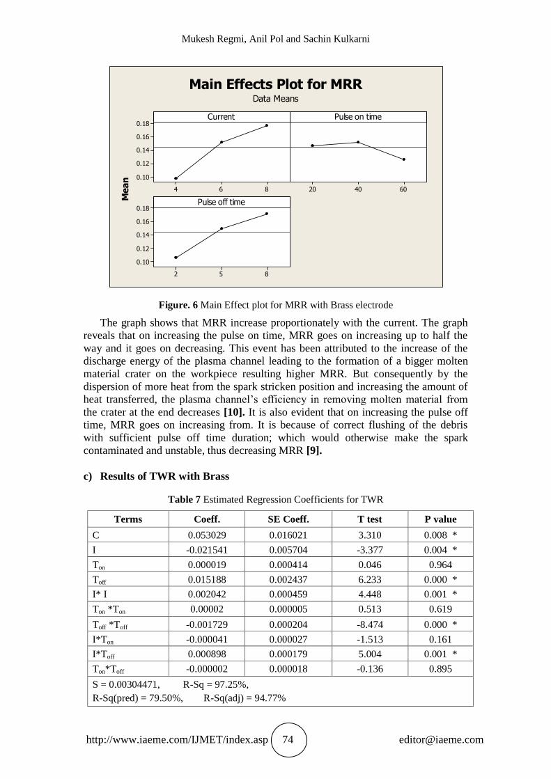
Figure. 6 Main Effect plot for MRR with Brass electrode
The graph shows that MRR increase proportionately with the current. The graph
reveals that on increasing the pulse on time, MRR goes on increasing up to half the
way and it goes on decreasing. This event has been attributed to the increase of the
discharge energy of the plasma channel leading to the formation of a bigger molten
material crater on the workpiece resulting higher MRR. But consequently by the
dispersion of more heat from the spark stricken position and increasing the amount of
heat transferred, the plasma channel’s efficiency in removing molten material from
the crater at the end decreases [10]. It is also evident that on increasing the pulse off
time, MRR goes on increasing from. It is because of correct flushing of the debris
with sufficient pulse off time duration; which would otherwise make the spark
contaminated and unstable, thus decreasing MRR [9].
c) Results of TWR with Brass
Table 7 Estimated Regression Coefficients for TWR
Terms Coeff. SE Coeff. T test P value
C 0.053029 0.016021 3.310 0.008 *
I -0.021541 0.005704 -3.377 0.004 *
Ton 0.000019 0.000414 0.046 0.964
Toff 0.015188 0.002437 6.233 0.000 *
I* I 0.002042 0.000459 4.448 0.001 *
Ton *Ton 0.00002 0.000005 0.513 0.619
Toff *Toff -0.001729 0.000204 -8.474 0.000 *
I*Ton -0.000041 0.000027 -1.513 0.161
I*Toff 0.000898 0.000179 5.004 0.001 *
Ton*Toff -0.000002 0.000018 -0.136 0.895
S = 0.00304471, R-Sq = 97.25%,
R-Sq(pred) = 79.50%, R-Sq(adj) = 94.77%

Multi Response Optimisation of Die Sinker EDM for Alsic Composite
http://www.iaeme.com/IJMET/index.asp 75 [email protected]
From the ANOVA table above, effect of current and pulse off time terms are
found to be statistically significant. Thus, the final model correlating TWR with
machining parameters is found as follows:
(6)
R2 value of 97.25 % indicates that, the variation in the response can be predicted
97 % correctly by using the above model developed for 90 % confidence interval.
864
0.06
0.05
0.04
0.03
604020
852
0.06
0.05
0.04
0.03
Current
Mean
Pulse on time
Pulse off time
Main Effects Plot for TWRData Means
Figure. 7 Main Effect plot for TWR with Brass tool
The graph shows that at the current of 4A, TWR is found to be minimum. Graph
depicted the linear increase in the value of TWR with current. The reason is that, at
low current a small quantity of heat is generated and a substantial portion of it is
absorbed by the surroundings, as a result, the amount of utilized energy in melting and
vaporizing the electrodes is not so intense. But by the increase in pulse current a
substantial quantity of heat will be transferred into the electrodes. Furthermore as the
pulse current increases, the discharge strikes the surface of the electrode more
intensely and creates an impact force on the molten material in the crater and causes
more molten material to be ejected out of the electrode [10].
The graph reveals that on increasing the pulse on time, TWR increases half the
way and goes on decreasing. Moreover longer pulse on time can provide enough time
for heavier positive ions attacking the cathode workpiece and hence removing more
material from the work than the tool [11].
It is also evident that on increasing the pulse off time, TWR goes on increasing
from 2μs to 5μs and almost showed a constant TWR after that. This is due to the fact
that the long pulse duration provides a better heat removal around the surface of brass
Mukesh Regmi, Anil Pol and Sachin Kulkarni
http://www.iaeme.com/IJMET/index.asp 76 [email protected]
electrode which is normally a good thermal conductor. The decrease in temperature
on the surface of electrode causes less wear on the electrode [4].
Thus the individual effect of pulse on time and pulse off time along with the
interaction effect between pulse on and pulse off time have the significant
contributions in MRR empirical response models for copper tungsten tool. Whereas
the individual effect of pulse off time along with the interaction effect between
current and pulse off time have the significant contributions in MRR empirical
response models for brass tool.
In TWR empirical response models, the individual effect of current and pulse off
time have the significant contributions in MRR empirical response models for copper
tungsten tool as well as brass tool but interaction effect between current and pulse on
time have the significant contributions in TWR with copper tungsten electrode and
interaction effect between current and pulse off time have the significant contributions
in TWR for brass tool.
6. CONCLUSION
Summarizing the main features the following conclusions can be drawn-
1. The predicted machining performance values match the experimental values
reasonably well; with R2 of 91.55% and 90.68% respectively for MRR and TWR
using copper tungsten as tool electrode and 95.57% and 97.25% respectively for
the MRR and TWR using brass as the tool electrode.
2. It has been observed that MRR as well as TWR goes on increasing with the
current.
3. It was observed that MRR goes on increasing with pulse on time till halfway and
goes on decreasing for both electrodes while TWR follows the same trend for
brass tool but TWR goes on decreasing with pulse on time for copper tungsten.
4. It has also been seen that MRR as well as TWR goes on increasing half the way
and decreases with pulse off time using copper tungsten as an electrode but for the
brass electrode MRR kept on increasing all the way with pulse off time and TWR
kept on increasing half the way and almost remained constant after that.
5. It has been observed that TWR goes on increasing with the current and MRR goes
on increasing with pulse on time till halfway and goes on decreasing.
6. Copper Tungsten electrode gave the higher MRR than the brass electrode. Not
only that TWR was also very less in CuW as compared to the brass electrode with
the same values of the machining conditions. So it is concluded that copper
tungsten is better than brass electrode.
REFERENCES
[1] Hassan Abdel- Gawad-El-Hofy, “Advanced Machining Processes”, Mc-Graw
Hill, Mechanical Engineering Series
[2] Dr. A.K. Sharma, http://nptel.iitm.ac.in/ Department of Mechanical Engineering,
IIT Roorkee
[3] P. Janmanee, A. Muttamara, “Performance of Difference Electrode Materials in
Electrical Discharge Machining of Tungsten Carbide” Energy Research Journal 1
(2): 87-90, 2010 , ISSN 1949-0151© 2010 Science Publications
[4] B. Mohan, A. Rajadurai, K.G. Satyanarayana, “Electric discharge machining of
Al–SiC metal matrix composites using rotary tube electrode”, Journal of
Materials Processing Technology 153–154 (2004) 978–985

Multi Response Optimisation of Die Sinker EDM for Alsic Composite
http://www.iaeme.com/IJMET/index.asp 77 [email protected]
[5] Harish K.Garg, Ketan Verma, Alakesh Manna, Rajesh Kumar, “Hybrid Metal
Matrix Composites and further improvement in their machinability”,
International Journal of Latest Research in Science and Technology
ISSN(Online):2278-5299Vol.1,Issue1:36-44,May-June(2012)
[6] S.L.Chen, M.H.Lin, S.F.Hsieh and S.Y.Chiou.; “The characteristics of
cutting pipe mechanism with multi-electrode in EDM”, Journal of material
processing technology Vol, 203, (2008), pp. 461-464.
[7] R.H. Myers, D. C. Montogomery, “Response Surface Methodology: Process and
Product Optimization using Designed Experiments”, 3rd
Edition, John Wiley and
Sons
[8] Mohan Kumar Pradhan and Chandan Kumar Biswas, “Modelling of machining
parameters for MRR in EDM using response surface methodology”, Proceedings
of NCMSTA’08 Conference ,National Conference on Mechanism Science and
Technology: from Theory to Application, November 13-14, 2008, National
Institute of Technology, Hamirpur
[9] M. S. Sohani . V. N. Gaitonde . B. Siddeswarappa . A. S. Deshpande,
“Investigations into the effect of tool shapes with size factor consideration in sink
electrical discharge machining (EDM) process”, International Journal of
Advanced Manufacturing Technology (2009) 45:1131_1145
[10] M.R. Shabgard, M. Seyedzavvar, S. Nadimi Bavil Oliaei, “Influence of input
parameters on characteristics of EDM process”, Journal of Mechanical
Engineering Volume(Year)No, StartPage-EndPage Paper received: 00.00.200x
UDC xxx.yyy.z Paper accepted: 00.00.200x
[11] S. Assarzadeh, M. Ghoreishi, “Statistical modeling and optimization of process
parameters in electro-discharge machining of cobalt-bonded tungsten carbide
composite (WC/6%Co)”, The Seventeenth CIRP Conference on Electro Physical
and Chemical Machining (ISEM), Procedia CIRP 6 ( 2013 ) 463 – 468