multi-objective optimization design of standard industrial
TRANSCRIPT

Journal of Science & Technology 147 (2020) 027-033
27
Multi-Objective Optimization Design of Standard Industrial Motor
Tran Tuan V*, Dang Chi D
Hanoi University of Science and Technology – No. 1, Dai Co Viet Str., Hai Ba Trung, Ha Noi, Viet Nam Received: September 14, 2020; Accepted: November 12, 2020
Abstract
This paper presents a method to optimally design electrical machines. Unlike the traditional design method “tries-and-errors iterative process”, the optimal design approach consists of combining optimization algorithms and multi-physics models to reach the optimum design. A case study of designing a standard industrial motor of 6 HP with multi-objectives and constraints is chosen in order to test this optimization methodology. The Pareto solution results of two conflicting objectives between the efficiency and the active mass of this machine are reached to help designers and customers selecting the best compromised design of motor of 6 HP in terms of cost and consuming energy.
Keywords: Optimal design; standard industrial motor; asynchronous motor; TEFC (totally enclosed fan cooled) machine; optimization.
1. Introduction*
Nowadays, electric motors present in many drive system applications such as standard industrial motor, pump, fan, metal cutting & forming machine, conveyor belt, servo robotic, woodworking/CNC, automatic door opener, railway transport, electric and hybrid vehicles, etc. [1-6]. The cost reduction competition between manufacturers has never stopped. Manufacturers need to further optimize the R&D cost, e.g. reducing loops of design and test; the manufacturing cost, e.g. reducing product mass, volume, production steps, changing materials, etc…
The design of electrical machinery has a long tradition and the “common approach” is a tries-and-errors iterative process, certainly converging but usually stopped prematurely because of extensive expense. A recent new methodology has been suggested by replacing physical prototypes and models with virtual prototypes, fully numerical, such as those provided by the finite element method [1]. Nevertheless, the process ends often with frustration, as the designer is uncertain about completely exploring the design space that has been offered to him. The optimal design approach proposes to improve this process through methodology and software tools: combining mathematical optimization algorithms and multi-physical, multi-level machine models. However, this approach is a complex, complicated, and multi-disciplinary task [1-12]. The researches about the mathematical optimization algorithms able to handle discrete variables and multi-level models are studied in [2, 7-11]. The multi-
* Corresponding author: Tel.: (+84) 906.298.290 Email: [email protected]
objective design problems in electrical engineering have been conducted in [5, 10, 11].
First, the optimal design approach applied for optimizing electrical machines will be presented. Then, the technical specification, the optimization formulation, and the Pareto optimum design results will be detailed in the next section multi-objective optimal design on a case-test of a standard industrial motor of 6 HP. Finally, discussions and conclusions will be given.
2. Optimal Design Approach
The optimal design approach of electrical machines can comprise five steps [11]. Those steps are linked sequentially but iterations and returns are often indispensable as described in Fig. 1.
Fig.1. Optimal design approach for electrical machines
2.1. Analyzing technical specification
The specification of an electromagnetic device design is defined by upstream manufacturers. It states the basic specifications, standard of a device, i.e. the need of users in terms of operation and constraints to
Analyzing Tech. Specification
Formulating Optim. problem
Modeling Device
Solving Optim. problem
Exploiting & Analyzing results
(I)
(II)
(III)
(IV)

Journal of Science & Technology 147 (2020) 027-033
28
be respected. For example, the information will be provided on the rated power, torque, speed, efficiency, inertia, fed by the power converter, or not.
2.2. Formulating optimization problem
This phase aims to translate the optimal design problem, described by the specification into an equivalent mathematical problem. This is the most delicate stage of the design process as the formulation of a problem is never unique, particularly the definition of the functions that characterize system performance [11, 12]. It must define accurately as in (1) and (2):
- The objective function(s);
- The design variables;
- The constraints related to the manufacturing or the use of the device expressed in the specifications;
- The extra constraints added by the designer.
Minimize
F(X) = (f1(X), f2(X),…, fp(X))
X = {x1, x2,…, xn} ∈ 𝑆𝑆 ⊂ ℝ𝑛𝑛
xi ∈ Di = {di1, xi2,…, diq}, i = 1,…,nd
xilb
≤ xi ≤ xiub, i = nd,…,n
(1)
Subject to
gj(X) ≤ 0, j = 1,…,l
hk(X) = 0, k = 1,…,m (2)
The objective function or the objective functions (f1(X), f2(X), …, fp(X)) are one or several criteria of the device that define the goal. They are the cost that can be minimized (e.g. active part, manufacturing cost, power consumption, etc.) or the performance that can be maximized (e.g. efficiency, power factor, etc.) in order to limit environmental impacts (e.g. depletion of natural resources, gas emissions, greenhouse effect, etc.).
The input variables or design parameters (X = {x1, x2,…, xn}) that influence performance will be changed during the iterations of optimal design process. They can be of various types: geometric dimensions of stator and rotor lamination shapes, material properties, structural topology, etc. These can be quantitative or qualitative, continuous, or discrete. The choice and number of variables also determine the definition of the optimization problem. It may be interesting to vary a large number of design variables to increase the search space but the optimization process will be lengthy and more difficult to solve.
The constraints (gj(X), hk(X)) related to multi-disciplinary electromagnetic – thermal-mechanical fields, to the manufacture and the uses, are expressed in the specifications. For example, the efficiency of power transformers or industrial motors must be high to improve the energy efficiency; the winding temperature must be lower than its limit insulation related to temperature rise class; the motor current needed to perform the maximum torque does not exceed the maximum current allowed by the power converter and the maximum power at high speeds must be greater or equal to that required in the specifications for servo motors, etc. Similarly, during the optimization process, the designer can add more constraints not expressed in the specifications but implicit for experts. For example, a constraint as the fulfilling factor is added in order to ensure that the winding does not exceed the stator slot; a maximum current density added to ensure thermal behavior; or when a parameter is calculated by a quadratic equation whose discriminator has to be greater than or equal to zero. These added constraints ensure the validity of the chosen model and the proper functioning of the optimization process.
2.3. Modeling device
Once the design problem is transformed into a mathematical problem, modeling the device is used to calculate the responses of the problem (objective function, constraints). The phenomena: electrical, magnetic, thermal, mechanical, acoustic can be modeled by empirical equations, analytical, or using the finite element method [5,8,11]. Expert knowledge of the designer for the device is required to have good accuracy models. This phase also allows the designer to better understand the physical phenomena in the electromagnetic device, especially with the help of modeling tools using the finite element method (FEM). The designer can observe the lines of flux and the magnetic induction saturation on the magnetic circuit, the torque oscillations, temperature gradients, etc.
The formulation of the optimization problem and modeling device is fundamental in the process of the optimal design of electrical machines because they determine the success of the next steps. They are complementary. The formulation of the problem is not easy to tackle because the choice of design variables is never unique and the current calculation means can only manage a limited number. An accurate and robust model is an asset for optimization algorithms.
2.4. Solving the optimization problem
The search for the optimal solution to a problem is realized by means of optimization methods. The
Journal of Science & Technology 147 (2020) 027-033
29
choice of optimization methods applied to the mathematical formulation in (1) depends on the nature of the problem (size of the problem, with or without constraints, continuous or discrete variables, single-objective or multi-objective problem, etc.). It also depends on the models of the device (analytic models, semi-analytic models, finite element models) to avoid excessive optimization computation time. Generally, there are two major families of optimization methods: deterministic and stochastic methods.
The optimization methods called deterministic (Simplex Nelder-Mead, SQP-Sequential Quadratic Programming, etc.) [11-13] lead to an initial solution always given to the same end result. To find the optimum, they are based on a search direction that can be provided by the derivatives of the objective function. These methods are rapidly converging but may converge to a local solution.
Stochastic methods: Genetic Algorithm (GA), Particle Swarm Optimization (PSO), etc. [12-13] as their names suggest, are based on probabilistic and random transition mechanisms that intelligently explore the search space and can converge to the global optimum. They require a large number of evaluations of the objective function, so a huge computation time in comparison with deterministic methods.
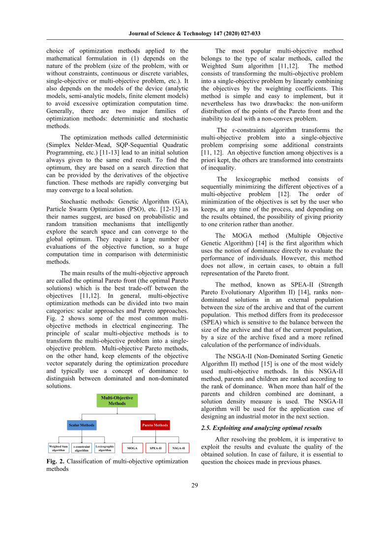
The main results of the multi-objective approach are called the optimal Pareto front (the optimal Pareto solutions) which is the best trade-off between the objectives [11,12]. In general, multi-objective optimization methods can be divided into two main categories: scalar approaches and Pareto approaches. Fig. 2 shows some of the most common multi-objective methods in electrical engineering. The principle of scalar multi-objective methods is to transform the multi-objective problem into a single-objective problem. Multi-objective Pareto methods, on the other hand, keep elements of the objective vector separately during the optimization procedure and typically use a concept of dominance to distinguish between dominated and non-dominated solutions.
Fig. 2. Classification of multi-objective optimization methods
The most popular multi-objective method belongs to the type of scalar methods, called the Weighted Sum algorithm [11,12]. The method consists of transforming the multi-objective problem into a single-objective problem by linearly combining the objectives by the weighting coefficients. This method is simple and easy to implement, but it nevertheless has two drawbacks: the non-uniform distribution of the points of the Pareto front and the inability to deal with a non-convex problem.
The ɛ-constraints algorithm transforms the multi-objective problem into a single-objective problem comprising some additional constraints [11, 12]. An objective function among objectives is a priori kept, the others are transformed into constraints of inequality.
The lexicographic method consists of sequentially minimizing the different objectives of a multi-objective problem [12]. The order of minimization of the objectives is set by the user who keeps, at any time of the process, and depending on the results obtained, the possibility of giving priority to one criterion rather than another.
The MOGA method (Multiple Objective Genetic Algorithm) [14] is the first algorithm which uses the notion of dominance directly to evaluate the performance of individuals. However, this method does not allow, in certain cases, to obtain a full representation of the Pareto front.
The method, known as SPEA-II (Strength Pareto Evolutionary Algorithm II) [14], ranks non-dominated solutions in an external population between the size of the archive and that of the current population. This method differs from its predecessor (SPEA) which is sensitive to the balance between the size of the archive and that of the current population, by a size of the archive fixed and a more refined calculation of the performance of individuals.
The NSGA-II (Non-Dominated Sorting Genetic Algorithm II) method [15] is one of the most widely used multi-objective methods. In this NSGA-II method, parents and children are ranked according to the rank of dominance. When more than half of the parents and children combined are dominant, a solution density measure is used. The NSGA-II algorithm will be used for the application case of designing an industrial motor in the next section.
2.5. Exploiting and analyzing optimal results
After resolving the problem, it is imperative to exploit the results and evaluate the quality of the obtained solution. In case of failure, it is essential to question the choices made in previous phases.
Multi-Objective Methods
Scalar Methods Pareto Methods
MOGA SPEA-II NSGA-IIWeighted Sum algorithm
ɛ-constraint algorithm
Lexicographic algorithm

Journal of Science & Technology 147 (2020) 027-033
30
Loop (I) in Fig. 1 is a return to the solving the problem phase. It can be motivated by a problem of convergence of the algorithm indicated by a stop of the procedure following an excessive computing time, or by obtaining an optimum local or a bad solution. It is then possible to modify the adjustment parameters of the algorithm for stochastic methods or the initial point for deterministic methods. Sometimes, it happens that the algorithm used is not or is little adapted to the treated problem, therefore it is advisable to change the optimization method or to modify the problem to facilitate its resolution.
When the resolution of the problem leads to an unrealizable or aberrant solution, the loop (II) in Fig. 1 questions the modeling phase of the device. It is necessary to check that there is no calculation error and that the described equations of the physical phenomena have taken reasonable assumptions, so the outputs are well calculated. Likewise, if the results do not change, the loop (III) is essential. It is a return to the formulation of the optimization problem. In this case, the approach allows the designer to refine his experience through a series of trials/errors during which he learns more about the limits of the models used and how to formulate the optimization problem to achieve relevant solutions. It is then advisable to add constraints to avoid imprecise or aberrant solutions, as well as other constraints to prevent the optimization algorithm not going into the areas of imprecision or fatal errors of the models.
The longest loop (IV) in Fig. 1 consists of returning to the analysis of the specifications when the solution is not feasible, or there is no solution because of too severe constraints or because the objective function is not relevant. It may happen that the design process leads to the conclusion that there is no solution to the specifications expressed. In this case, the designer relaxes the constraints to arrive at a feasible solution by dialoguing with the client to decide on the possible choices.
3. Multi-Objective Design of an Industrial Motor
3.1. Technical Specification
Fig. 3 shows cross sections of a typical industrial TEFC (Totally Enclosed Fan Cooled) motor. This foot mounting motor is an asynchronous machine with aluminum cage die-casting rotor. The standard technical specification of a 6 HP motor directly connected to 3-phases electric network with the line-to-line voltage of 380 Vrms and frequency of 50 Hz requires 4.5 kW mechanical output power; the synchronous speed of 1500 rpm; efficiency and power factor of 85 % and 0.8; maximum torque ratio of 2.2; starting torque ratio of 2.0; starting current ratio of 6.0.
Fig. 3. Cross sections of a standard industrial motor
3.2. Optimization formulation design problem
The multi-objective optimization problem of a standard industrial motor can be formulated as:
- 02 objective functions:
o maximize the efficiency of the motor
o minimize the total active mass of motor (stator/rotor cores & copper winding, aluminum cage)
- 12 design variables:
o outer/inner stator diameters
o active length of stator/rotor cores
o all dimensions of stator/rotor slots
o number of turns and number of wires
o motor slip
- 09 multi-disciplinary equality and inequality constraints:
o output power ~1500rpm = 4.5 kW
o manufacturing fulfill slot ≤ 80%
o current density ≤ 4.5 A/mm2
o power factor ≥ 0.8
o maximum torque ratio ≥ 2.2
o starting torque ratio ≥ 2.0
o starting current ratio ≥ 6.0
o others on the feasibility of dimensions,…
Two conflicting objectives are chosen: maximizing the efficiency and minimizing the electromagnetic active mass of motor containing (stator/rotor electrical steel lamination cores, copper stator winding and aluminum rotor cage). Modifying 12 design variables directly impacts the cost and efficiency of the motor. The multi-objective optimization design of this standard industrial motor of 6 HP consists to find the best trade-off (Pareto front) between these both conflicted objectives.

Journal of Science & Technology 147 (2020) 027-033
31
Fig. 4. Efficiency-Active Mass multi-objective results Fig. 6. Main motor parameters
Fig. 5. Main design variables of 7000 evaluations Fig. 7. Pareto optimal front results (zoom)
3.3. Optimal design results
Using NSGA-II with a set-up of the population size of 70 and 100 generations, coupling to an analytical electromagnetic model in Matlab environment, the results of the whole 7000 evaluations of model are shown in Fig. 4-6. The results of both conflicting objectives: maximizing the efficiency and minimizing the motor active mass are presented in Fig.4. The best compromise, Pareto front is converging in the area of 85% of efficiency and will be zoomed in Fig. 7.
Fig. 5 presents the main design variables: outer/inner stator diameters, core length, number of turns per slot and number of wires per turn during the optimization process. The continuous design variables values vary [150:220] mm, [100:170] mm and [150:210] mm for outer, inner stator diameters and core length respectively. The discrete design variables such as the number of turns per slot and number of wires vary respectively {15:21} turns and {3:9} standard wires of 0.8 mm of diameter.
Motor mechanical output and electric input powers during the optimization calculations can be observed in Fig. 6. The mechanical power values are kept constant of 4.5 kW as well as constraint requirement while the ones of electric power vary depending on each design and converge closing to the output power (better efficiencies). The motor current (Fig. 6) is a reflected image of the input power while the output power is kept constant. Some designs are not feasible because they do not respect constraint requirements such as the fulfill coefficient values are higher than 80% as seen in Fig. 6.
The Pareto front is detailed in Fig. 7. With the same materials (electrical steel M470-50A, copper winding and aluminum cage), the best trade-off between efficiency and active masse is obtained: variation of 85% ÷ 87.5% for 34 kg ÷ 46 kg for this industrial motor of 6 HP. Using another electrical steel with lower iron losses (i.e. M330-50A, 3.3 W/kg vs 4.7 W/kg) [4] and/or copper rotor cage can improve the efficiency of a motor, then change the characteristic of this Pareto front.
Active Mass (kg)
15 20 25 30 35 40 45 50 55
Effic
ienc
y (%
)
0
10
20
30
40
50
60
70
80
90
100Motor efficiency - 7000 evaluations
Pareto front
Active Mass (kg)
15 20 25 30 35 40 45 50 55
Cur
rent
/ Fu
lfill
/ Pin
/ Po
ut
0
10
20
30
40
50
60
70
80
90
100Main parameters
Fulfill Coef. (-)
Current (A)
Pin (kW)
Pout(kW)
Active Mass (kg)
15 20 25 30 35 40 45 50 55
Dou
t / D
in /
Lact
/ N
br tu
rns
/ Nbr
wire
s
0
50
100
150
200
250Main design variables
Dout (mm)
Din (mm)
Lact (mm)
Nbr turns (-)
Nbr wires (-)
Active Mass (kg)
34 36 38 40 42 44 46
Effic
ienc
y (%
)
85
85.5
86
86.5
87
87.5Pareto optimal front
*01 selected
Optimal Design
Journal of Science & Technology 147 (2020) 027-033
32
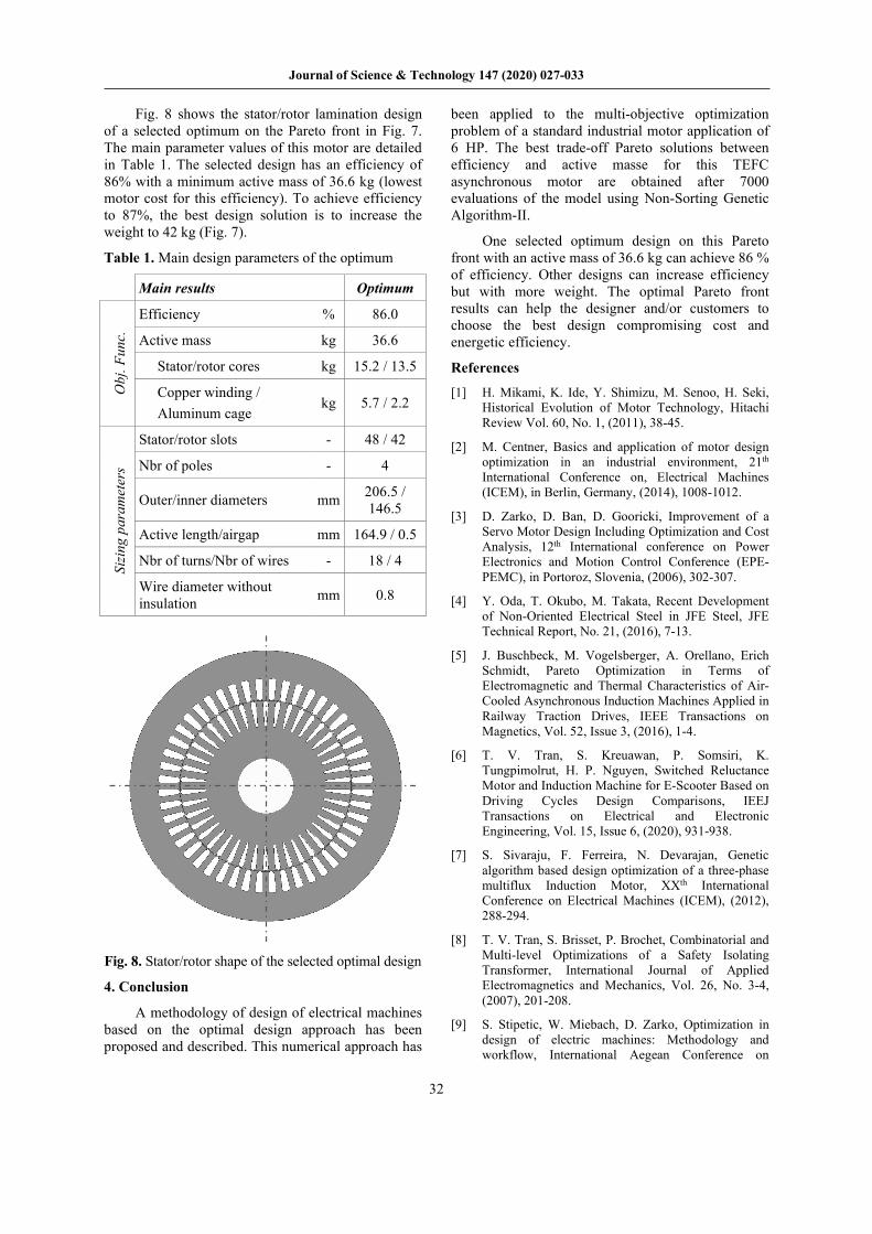
Fig. 8 shows the stator/rotor lamination design of a selected optimum on the Pareto front in Fig. 7. The main parameter values of this motor are detailed in Table 1. The selected design has an efficiency of 86% with a minimum active mass of 36.6 kg (lowest motor cost for this efficiency). To achieve efficiency to 87%, the best design solution is to increase the weight to 42 kg (Fig. 7).
Table 1. Main design parameters of the optimum
Main results Optimum
Obj
. Fun
c.
Efficiency % 86.0
Active mass kg 36.6
Stator/rotor cores kg 15.2 / 13.5
Copper winding / Aluminum cage
kg 5.7 / 2.2
Sizi
ng p
aram
eter
s
Stator/rotor slots - 48 / 42
Nbr of poles - 4
Outer/inner diameters mm 206.5 / 146.5
Active length/airgap mm 164.9 / 0.5
Nbr of turns/Nbr of wires - 18 / 4
Wire diameter without insulation mm 0.8
Fig. 8. Stator/rotor shape of the selected optimal design
4. Conclusion
A methodology of design of electrical machines based on the optimal design approach has been proposed and described. This numerical approach has
been applied to the multi-objective optimization problem of a standard industrial motor application of 6 HP. The best trade-off Pareto solutions between efficiency and active masse for this TEFC asynchronous motor are obtained after 7000 evaluations of the model using Non-Sorting Genetic Algorithm-II.
One selected optimum design on this Pareto front with an active mass of 36.6 kg can achieve 86 % of efficiency. Other designs can increase efficiency but with more weight. The optimal Pareto front results can help the designer and/or customers to choose the best design compromising cost and energetic efficiency.
References
[1] H. Mikami, K. Ide, Y. Shimizu, M. Senoo, H. Seki, Historical Evolution of Motor Technology, Hitachi Review Vol. 60, No. 1, (2011), 38-45.
[2] M. Centner, Basics and application of motor design optimization in an industrial environment, 21th International Conference on, Electrical Machines (ICEM), in Berlin, Germany, (2014), 1008-1012.
[3] D. Zarko, D. Ban, D. Gooricki, Improvement of a Servo Motor Design Including Optimization and Cost Analysis, 12th International conference on Power Electronics and Motion Control Conference (EPE-PEMC), in Portoroz, Slovenia, (2006), 302-307.
[4] Y. Oda, T. Okubo, M. Takata, Recent Development of Non-Oriented Electrical Steel in JFE Steel, JFE Technical Report, No. 21, (2016), 7-13.
[5] J. Buschbeck, M. Vogelsberger, A. Orellano, Erich Schmidt, Pareto Optimization in Terms of Electromagnetic and Thermal Characteristics of Air-Cooled Asynchronous Induction Machines Applied in Railway Traction Drives, IEEE Transactions on Magnetics, Vol. 52, Issue 3, (2016), 1-4.
[6] T. V. Tran, S. Kreuawan, P. Somsiri, K. Tungpimolrut, H. P. Nguyen, Switched Reluctance Motor and Induction Machine for E-Scooter Based on Driving Cycles Design Comparisons, IEEJ Transactions on Electrical and Electronic Engineering, Vol. 15, Issue 6, (2020), 931-938.
[7] S. Sivaraju, F. Ferreira, N. Devarajan, Genetic algorithm based design optimization of a three-phase multiflux Induction Motor, XXth International Conference on Electrical Machines (ICEM), (2012), 288-294.
[8] T. V. Tran, S. Brisset, P. Brochet, Combinatorial and Multi-level Optimizations of a Safety Isolating Transformer, International Journal of Applied Electromagnetics and Mechanics, Vol. 26, No. 3-4, (2007), 201-208.
[9] S. Stipetic, W. Miebach, D. Zarko, Optimization in design of electric machines: Methodology and workflow, International Aegean Conference on

Journal of Science & Technology 147 (2020) 027-033
33
Electrical Machines and Power Electronics and Advanced Electromechanical Motion Systems (ACEMP – OPTIM – ELECTROMOTION), Turkey, (2015), 441-448.
[10] Y. Duan, R. G. Harley, A Novel Method for Multi-objective Design and Optimization of Three Phase Induction Machines, IEEE Transactions on Industry Applications, Vol. 47, Issue 4, (2011), 1707-1715.
[11] T. V. Tran, Problèmes combinatoires et modèles multi-niveaux pour la conception optimale des machines électriques, Ph.D. dissertation, École Centrale de Lille, France, (2009).
[12] J. S. Arora, Introduction to Optimum Design, Publisher Elsevier Science & Technology (2004).
[13] P. Venkataraman, Applied Optimization with Matlab Programming, A Wiley – Interscience publication, John Wiley & Sons, New York, (2002).
[14] C. A. Coello, G. B.Lamont, Application of Multi-Objective Evolutionary Algorithms, Advances in Natural Computation - Vol. 1, World Scientific Publishing Co. Pte. Ltd., (2004).
[15] K. Deb, S. Agrawal, A. Pratap, T. Meyarivan, A fast elitist non-dominated sorting genetic algorithm for multi-objective optimization: NSGA-II, IEEE Transactions on Evolutionary Computation, Vol. 6, No. 2, (2002), 182-197.