multi-layer virtual network embedding
TRANSCRIPT
1132 IEEE TRANSACTIONS ON NETWORK AND SERVICE MANAGEMENT, VOL. 15, NO. 3, SEPTEMBER 2018
Multi-Layer Virtual Network EmbeddingShihabur Rahman Chowdhury , Student Member, IEEE, Sara Ayoubi, Reaz Ahmed,
Nashid Shahriar , Student Member, IEEE, Raouf Boutaba , Fellow, IEEE, Jeebak Mitra , and Liu Liu
Abstract—Network virtualization (NV), considered as a keyenabler for overcoming the ossification of the Internet allowsmultiple heterogeneous virtual networks to co-exist over thesame substrate network. Resource allocation problems in NVhave been extensively studied for single layer substrates suchas IP or Optical networks. However, little effort has been putto address the same problem for multi-layer IP-over-opticalnetworks. The increasing popularity of multi-layer networks fordeploying backbones combined with their unique characteristics(e.g., topological flexibility of the IP layer) calls for the need tocarefully investigate the resource provisioning problems arisingfrom their virtualization. In this paper, we address the problem ofmulti-layer virtual network embedding (MULE; similar to multi-layer networks, this hybrid species brings the best of two speciestogether.) on IP-over-optical networks. We propose two solutionsto MULE: 1) an integer linear program formulation for theoptimal solution (OPT-MULE) and 2) a heuristic to address thecomputational complexity of the optimal solution (FAST-MULE).We demonstrate through extensive simulations that on averageour heuristic performs within ≈1.47× of optimal solution whileexecuting several orders of magnitude faster. Simulation resultsalso show that FAST-MULE incurs ≈66% less cost on averagethan the state-of-the-art heuristic while accepting ≈60% morevirtual network requests on average.
Index Terms—Computer network management, overlaynetworks.
I. INTRODUCTION
MULTI-LAYER IP-over-Optical networks are becom-ing a popular choice among Infrastructure Providers
(InPs) for deploying wide area networks [1]. Such multi-layer network typically consists of an optical substrate for thephysical communication with an IP overlay on top [2]. Thisnetwork model is being increasingly adopted for backbone
Manuscript received March 2, 2018; accepted May 3, 2018. Date of pub-lication May 8, 2018; date of current version September 7, 2018. Thiswork was supported in part by Huawei Technologies and in part by anNSERC Collaborative Research and Development Grant. Additionally, thiswork benefited from the use of the CrySP RIPPLE Facility at the Universityof Waterloo. The associate editor coordinating the review of this paperand approving it for publication was C. Fung. (Corresponding author:Shihabur Rahman Chowdhury.)
S. R. Chowdhury, R. Ahmed, N. Shahriar, and R. Boutaba are with theDavid R. Cheriton School of Computer Science, University of Waterloo,Waterloo, ON N2L 3G1, Canada (e-mail: [email protected];[email protected]; [email protected]; [email protected]).
S. Ayoubi is with INRIA, 75012 Paris, France (e-mail:[email protected]).
J. Mitra is with Huawei Technologies Canada Research Center, Ottawa,ON K2K 3J1, Canada (e-mail: [email protected]).
L. Liu is with Huawei Technologies Company, Ltd., Chengdu, China(e-mail: [email protected]).
Digital Object Identifier 10.1109/TNSM.2018.2834315
networks as it offers the best of both worlds, i.e., the flexibil-ity in addressing, resource allocation, and traffic engineeringof IP networks along with the high capacity provided by opti-cal networks. Despite their increasing popularity, research onaddressing resource provisioning challenges for virtualizingsuch networks is still in its infancy. A classical resource provi-sioning problem in network virtualization is Virtual NetworkEmbedding (VNE), which consists in establishing a VirtualNetwork (VN) on a Substrate Network (SN) with objec-tives such as minimizing resource provisioning cost [3], [4],maximizing the number of admitted VNs [5], etc. VNE hasbeen extensively studied for single-layer SNs [6] with sig-nificantly lesser attention paid to the multi-layer networksubstrates [7]. The topological flexibility provided by multi-layer networks [8] poses some unique challenges for VNE andcalls for new investigations.
Several deployment models exist for multi-layer IP-over-Optical networks [9] including but not limited to: (i) IP overDense Wavelength Division Multiplexed (DWDM); (ii) IPover Optical Transport Network (OTN) over DWDM. DWDMnetworks have specific constraints such as wavelength conti-nuity for optical circuits and typically do not have transparenttraffic grooming capabilities. A more favorable choice (alsoour choice of technology) is to deploy an OTN [10] overa DWDM network with advanced transport capabilities (e.g.,traffic grooming without optical-electrical-optical conversion).The OTN in turn can be static, i.e., necessary interfaceson OTN nodes have been configured and the correspondinglight paths in the DWDM layer have been lit to provisionfixed bandwidth between OTN nodes. Or, the OTN can bedynamic, i.e., more bandwidth between OTN nodes can be pro-visioned by lighting new light paths in the DWDM. Clearly,the VNE problem for each of these scenarios requires dedi-cated explorations due to their unique constraints. As a firststep towards addressing VNE for multi-layer networks, welimit the scope of this paper to the case of a static OTNand leave the other possible deployment scenarios for futureinvestigation.
Solving the VNE problem for multi-layer networks exhibitsmany unique challenges due to the topological flexibilityoffered by such networks. Concretely, although the OTN isfixed, the IP network is dynamic, i.e., new IP links can beestablished when needed by provisioning necessary capacityfrom the OTN. Such flexibility can be exploited if residualresources in the IP layer are insufficient to admit a new VN,or to reduce the cost of VN embedding by creating new IPlinks that reduce network diameter. Provisioning new IP linksin optical networks has been a tedious and manual task with a
1932-4537 c© 2018 IEEE. Personal use is permitted, but republication/redistribution requires IEEE permission.See http://www.ieee.org/publications_standards/publications/rights/index.html for more information.

CHOWDHURY et al.: MULTI-LAYER VNE 1133
long turnaround time. However, with the advances in opticalnetworking technologies [11] and centralized optical controlplane [12]–[15], such provisioning tasks are more and moreautomated. Even then, one should not abuse such capabilityto sporadically establish new IP links since it remains moreexpensive than embedding virtual links on existing IP links.In this regard, we are faced with the following challenges:(i) strike a balance between obtaining a low cost VN embed-ding while minimizing the establishment of new IP links;(ii) simultaneously decide on whether to create an IP link ornot and its embedding in the OTN.
In this paper, we study the problem of MUlti-Layer VirtualNetwork Embedding (MULE) focusing on IP-over-OTN sub-strate networks with the objective of minimizing total resourceprovisioning cost for embedding the VN while consideringthe possibility of establishing new IP links when necessary.Specifically, the contributions of this paper are as follows:
• OPT-MULE: An Integer Linear Program (ILP) formula-tion to find the optimal solution to MULE. The state-of-the-art in multi-layer VNE [7] does not optimally solvethe problem. To the best of our knowledge, this is thefirst optimal solution the VNE problem for multi-layerIP-over-OTN networks.
• FAST-MULE: A heuristic to tackle the computationalcomplexity of OPT-MULE. We also prove that ourheuristic solves the problem optimally for a specificclass of VNs, i.e., star-shaped VNs. For arbitrary VNs,trace driven simulations show that FAST-MULE uses≈1.47× more resources on average compared to OPT-MULE while executing several orders of magnitudefaster. Further, our comparative analysis shows thatFAST-MULE allocates ≈66% less resources on averagecompared to the state-of-the-art heuristic for multi-layerVNE [7], while accepting ≈60% more VN requests onaverage.
This paper extends our initial work presented in [16] onthe following aspects. First, we provide a guideline on how toparallelize the proposed heuristic and leverage modern multi-core CPUs. Second, we perform more extensive performanceevaluation of the proposed heuristic by performing a steadystate analysis. The steady state analysis involves performanceevaluation while considering arrival and departure of VNsover a longer period of time as opposed to performingmicro-benchmarking for single VN instances. We comparethe steady state performance of our proposed heuristic withthat of the state-of-the-art heuristic for multi-layer VN embed-ding [7]. Finally, we present a more elaborate discussion on theresearch literature and contrast our contributions to the relatedworks.
The rest of the paper is organized as follows. We beginwith a discussion of related works in Section II. Then weintroduce the mathematical notations representing the inputsto the problem and formally define the problem in Section III.In Section IV, we present OPT-MULE, an ILP formulation tooptimally solve MULE, followed by our proposed heuristic,FAST-MULE in Section V. Our evaluation of the proposedsolutions are presented in Section VI. Finally, we concludewith some future research directions in Section VII.
II. RELATED WORKS
A. Virtual Network Embedding
VNE is a well studied problem in network virtualizationand a significant body of research has solved a number ofits variants [4], [17]–[27]. However, it has been mostly stud-ied for single layer SNs, i.e., for IP, Optical or Wirelessnetworks. Despite the existence of a significant number of pro-posals [28]–[30], VNE solutions for IP networks commonlyinvolve allocating compute and bandwidth resources for thevirtual nodes and links, respectively. In the case of opticalnetworks, solving VNE involves allocating compute resourcesand wavelength for virtual nodes and links, respectively [31].Optical networks have technological constraints such as dis-crete wavelength allocation, wavelength continuity etc. thatadd additional challenges to the VNE problem [32]. The state-of-the-art in optical network virtualization has mostly focusedon single layer optical networks.
B. Multi-Layer Embedding
A few works in the research literature addressed theproblem of embedding in multi-layer networks [7], [33], [34].Savi et al. [33] consider the problem of application-aware traf-fic embedding on IP/Multi-layer Protocol Switching(MPLS)-over-Optical Network. Traffic requests are given between pairsof routers in the network, where each request has differentiatedservice requirements in terms of bandwidth, tolerable end-to-end delay, and tolerable end-to-end path availability. Here, thepossibility of establishing new IP links is also considered whenthe IP/MPLS layer does not have sufficient capacity to meetthe demand of a given request. However, in [33], the end pointsof the requests are fixed and it only addresses the link routingproblem. Moreover, [33] neither does propose an optimal solu-tion to the problem, nor presents complexity analysis of theproposed heuristic. Furthermore, the creation of new IP links isrestricted to the pair of IP nodes that are not already connected.In [34], the problem of Service Function Chaining (SFC) inIP-over-OTN networks is addressed. This work considers ser-vice function chains distributed across multiple data centers,where the data centers, representing the electronic layer, areinterconnected via an optical network. The authors proposean algorithm in [34] to route each SFC request across thedata centers. Therefore, even though the substrate network isa multi-layer one, the routing problem is addressed only infor optical layer. Furthermore, the placement of the networkfunctions in the requested SFC is considered given, and thedifferent segments (pair of service functions) that make up theSFC are routed sequentially.
To the best of our knowledge, the only work that consid-ered the problem of multi-layer virtual network embeddingwhile considering both node and link embedding is presentedin [7]. Zhang et al., proposed a heuristic for solving themulti-layer VNE problem for IP-over-DWDM networks. Theyalso consider the possibility of modifying IP layer topol-ogy by allocating wavelengths from the underlying DWDMnetwork. Zhang et al., proposed a two step embedding pro-cess that first embeds the virtual nodes then the virtual links,which limits the solution space and hence the optimality of
1134 IEEE TRANSACTIONS ON NETWORK AND SERVICE MANAGEMENT, VOL. 15, NO. 3, SEPTEMBER 2018
the embedding. In contrast, we propose an ILP formulationfor optimally solving the multi-layer VNE problem. Also,our heuristic does not embed the virtual nodes and linksindependently from each other, rather tries to embed themsimultaneously.
C. Multi-Layer Network Optimization
An orthogonal but somehow related area of research inmulti-layer network optimization focused on the issue ofcapacity planning in multi-layer networks [32], [35]. Duringthe initial capacity planning a traffic matrix for the IP layeris given and sufficient capacity needs to be allocated inboth IP and Optical layers to support that traffic matrix.Different variants of the problem exist that take differ-ent technological constraints and deployment models intoaccount [36]–[39]. While the results from [36] are applicablefor generic multi-layer network, however, that from [37] is spe-cific to IP/MPLS-over-OTN-over-DWDM optical networks,with particular emphasis on the technological constraints ofthe OTN layer. Similar to [37], the work presented in [38] con-siders the capacity planning problem for OTN-over-DWDMnetworks.
Another research direction, that has been well exploredin the research literature is that of protection planning formulti-layer networks [40]–[44]. Multi-layer protection plan-ning involves deciding which layer will be in charge of pro-tecting what, and coordinating the protection schemes acrossdifferent layers [40], [45]. For instance, Gerstel et al. [45]showcase the limitations of traditional capacity planning in IP-over-OTN networks where each layer is treated in isolation.Subsequently, the authors motivate the advantages of coordi-nating across the different layers, and illustrate these benefitsin Multi-Layer Restoration (MLR) planning. To achieve theirgoals, the authors compared MLR against restoration planningperformed at the IP-layer alone and showed significant sav-ings in the number of interfaces used and provisioned networkresources (i.e., wavelengths in their case). Bigos et al. [41]address the problem of designing a multi-layer protectionscheme for MPLS-over-OTN networks. They evaluate singleand multi-layer survivability schemes under different sparecapacity allocation strategies (e.g., shared vs. dedicated). Inthe single layer survivability scheme, they propose to protectevery Label Switched Path (LSP) against failures in the IPor in the OTN layer. Whereas, in the multi-layer survivabilityscheme, the OTN layer is protected against physical link andOXC failures, and the IP layer is protected against routers andIP/Optical interface failures.
In contrast to capacity and protection planning, in multi-layer VNE, the endpoint of the demands, i.e., virtual nodeplacement, is not known in advance, making this one a fun-damentally different problem. Further, the body of researchin multi-layer capacity and protection planning has demon-strated clear advantages of resource allocation when thelayers are jointly optimized as opposed to considering themin isolation [41], [45], [46]. Our solution approach alsotakes a joint optimization approach to the multi-layer VNEproblem.
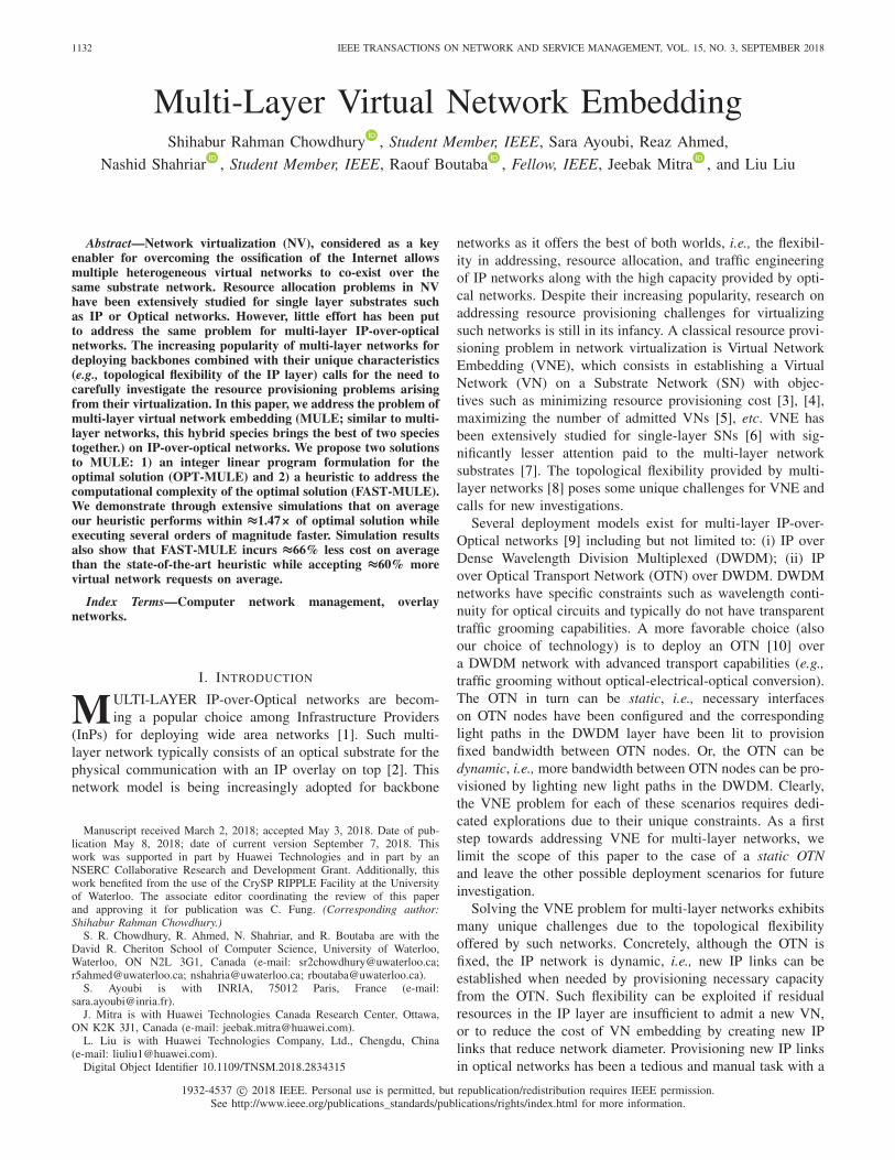
Fig. 1. MULE Illustrative Example.
III. MULE: MULTI-LAYER VIRTUAL NETWORK
EMBEDDING PROBLEM
We first present a mathematical representation of the inputs,i.e., the IP topology, the OTN topology, and the VN request.Then we give a formal definition of MULE, followed by anillustrative example.
A. Substrate Optical Transport Network (OTN)
We represent the substrate OTN as an undirected graph G =(V , E ), where V and E are the set of OTN capable devices(referred as OTN nodes in the remaining) and OTN links,respectively. Without loss of generality we assume the OTNlinks to be undirected, since such undirected OTN links canbe either supported by specific technologies [47], [48] or bylaying out multiple unidirectional fibers, or by using differentwavelengths for sending and receiving within a single strand offiber. Neighbors of an OTN node u are represented with N (u).We assume the OTN to be fixed, i.e., light paths atop a DWDMlayer have been already lit to provision OTN links (u, v) withbandwidth capacity bu v . This pre-provisioned bandwidth canbe used to establish IP links between IP routers. The cost ofallocating one unit of bandwidth from an OTN link (u, v) ∈ Eis Cu v . Fig. 1 illustrates an example of an OTN network,where the numbers on each link represent its residual capacity.
B. Substrate IP Network
The substrate IP network is an undirected graph G′ =(V′, E′). Each IP node u ′ ∈ V ′ has pu′ number of ports withhomogeneous capacity capu′ . Each IP node u′ is connectedto an OTN node τ(u ′) through a short-reach wavelengthinterface. Attachment between an IP and an OTN node is rep-resented using a binary input variable τu′u , which is set to 1only when IP node u′ is attached to OTN node u . An IP linkis provisioned by establishing an OTN path that connects itsend points. Note that, it is common in operator networks toestablish multiple IP links between the same pair of IP nodesand bundle their capacities using some form of link aggre-gation protocol [49]. We also follow the same practice anduse (u′, v′, i) to represent the i-th IP link between u′ and v′,where 1 ≤ i ≤ pu′ . We use the binary input variable Γu′v ′ito indicate the existence of an IP link (u′, v′, i) in G′. Γu′v ′iis set to 1 when IP link (u′, v′, i) is present in G′, otherwise itis set to 0. Bandwidth of an IP link is represented by bu′v ′i .
CHOWDHURY et al.: MULTI-LAYER VNE 1135
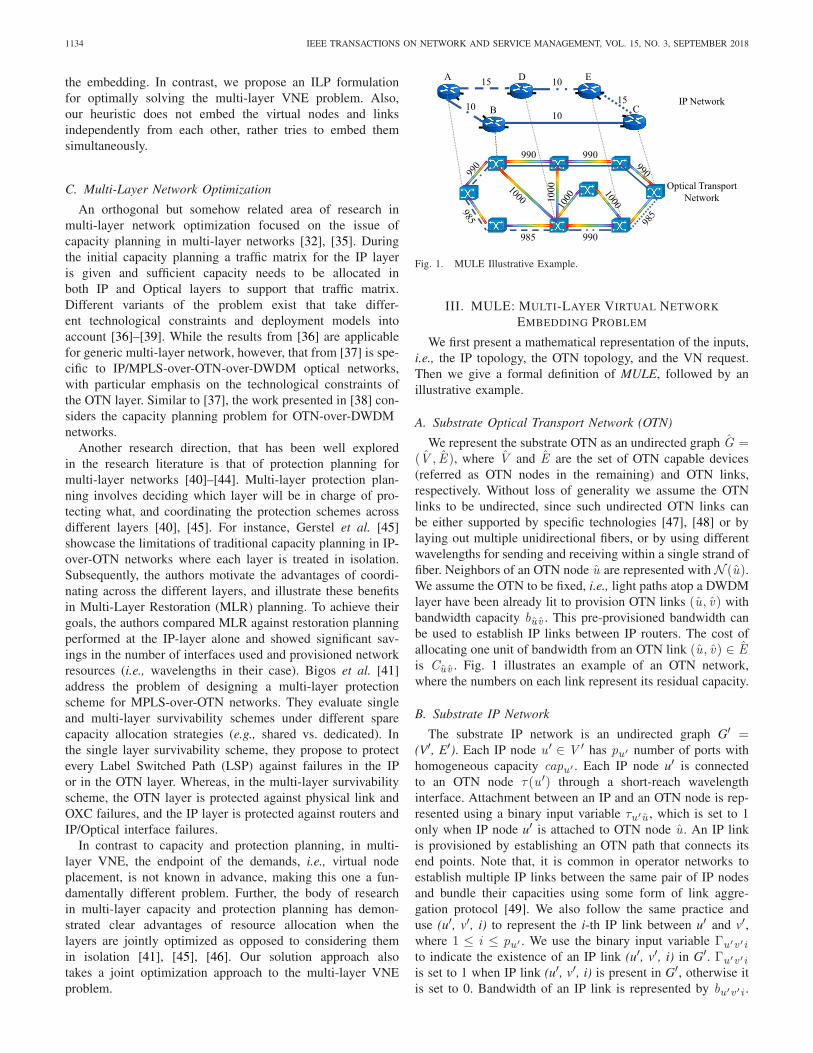
Fig. 2. Virtual Network.
Capacity of a new IP link (u′, v′, i) is set to min(capu′ , capv ′).Fig. 1 illustrates an example IP network, where each IP linkis mapped on an OTN path and the residual bandwidth capac-ity of an IP link is represented by the number on that link.The cost of allocating one unit of bandwidth from an IP link(u′, v′, i) ∈ E ′ is Cu′,v ′,i .
C. Virtual Network (VN)
A VN request is an undirected graph G = (V , E ), whereV and E are the set of virtual nodes (VNodes) and virtuallinks (VLinks), respectively. Each VLink (u, v) ∈ E has abandwidth requirement bu v . Each VNode u ∈ V has a loca-tion constraint set L(u) ⊂ V ′ that represents the set of IPnodes where u can be embedded. L(u) can be determined bythe InP based on geographical proximity requirement by theSP. Note that L(u) can contain all the IP nodes to represent anunconstrained scenario. We represent the location constraintsusing a binary input variable �uu′ , which is set to 1 if IP nodeu ′ ∈ L(u). Fig. 2 illustrates a VN, where the number on eachlink represents VLink demand, and the set next to each nodedenotes that VNode’s location constraints.
D. Problem Definition
Given a multi-layer SN composed of an IP network G′ ontop of an OTN network G , and a VN request G with locationconstraint set L:
• Map each VNode u ∈ V to an IP node u ′ ∈ V ′according to the VNode’s location constraint.
• Map each VLink (u, v) ∈ E to a path in the IP network.This path can contain a combination of existing IP linksand newly created IP links.
• Map all newly created IP links to a path in the OTN.• The total cost of provisioning resources for new IP links
and cost of provisioning resources for VLinks should beminimized subject to the following constraints:
– IP links cannot be over-committed to accommodatethe VLinks, and
– the demand of a single VLink should be satisfied bya single IP path.
The embedding is subject to the constraints that bothIP links and OTN links cannot be over-provisioned, andVLinks and IP links cannot be routed along multiple IPpaths and multiple OTN paths, respectively (i.e., no path split-ting). Moreover, we do not consider neither VNode resourcerequirement nor VNode embedding cost. We assume that thevirtualization enabled network devices have enough capac-ity to switch at line rate between any pair of ports and anycomplex control mechanism is decoupled and performed in acentralized control plane. Finally, we consider online versionof the problem where VN requests arrive one at a time.
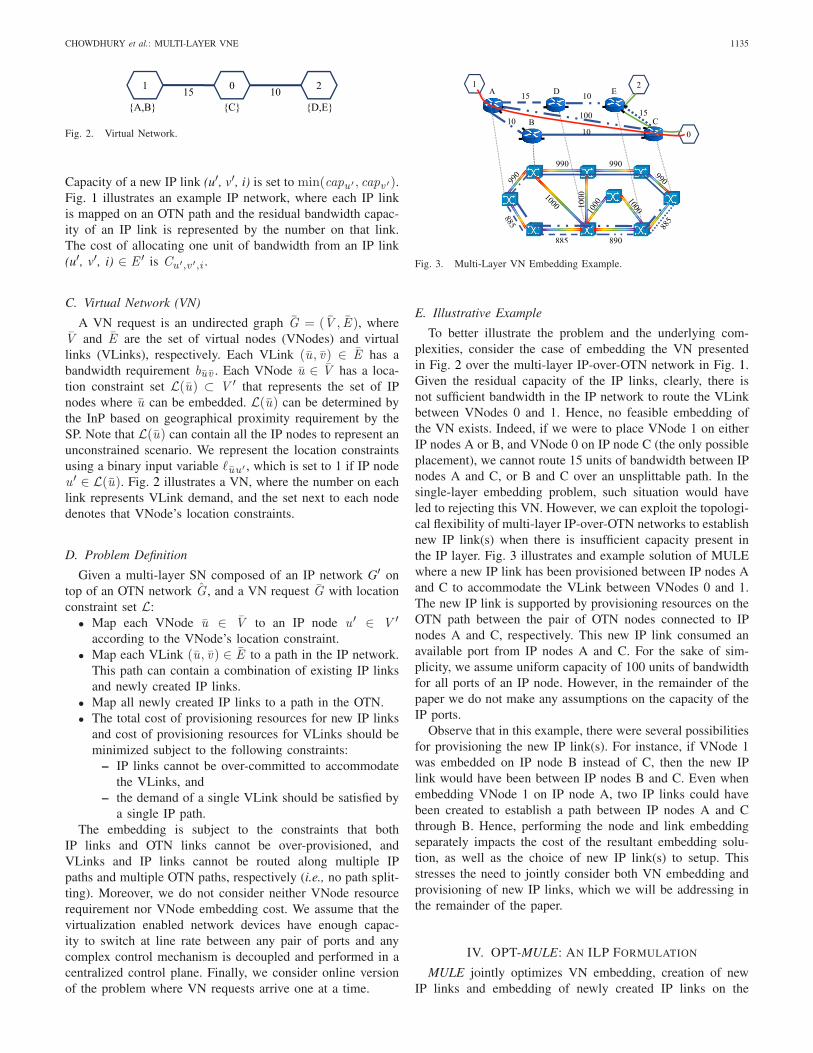
Fig. 3. Multi-Layer VN Embedding Example.
E. Illustrative Example
To better illustrate the problem and the underlying com-plexities, consider the case of embedding the VN presentedin Fig. 2 over the multi-layer IP-over-OTN network in Fig. 1.Given the residual capacity of the IP links, clearly, there isnot sufficient bandwidth in the IP network to route the VLinkbetween VNodes 0 and 1. Hence, no feasible embedding ofthe VN exists. Indeed, if we were to place VNode 1 on eitherIP nodes A or B, and VNode 0 on IP node C (the only possibleplacement), we cannot route 15 units of bandwidth between IPnodes A and C, or B and C over an unsplittable path. In thesingle-layer embedding problem, such situation would haveled to rejecting this VN. However, we can exploit the topologi-cal flexibility of multi-layer IP-over-OTN networks to establishnew IP link(s) when there is insufficient capacity present inthe IP layer. Fig. 3 illustrates and example solution of MULEwhere a new IP link has been provisioned between IP nodes Aand C to accommodate the VLink between VNodes 0 and 1.The new IP link is supported by provisioning resources on theOTN path between the pair of OTN nodes connected to IPnodes A and C, respectively. This new IP link consumed anavailable port from IP nodes A and C. For the sake of sim-plicity, we assume uniform capacity of 100 units of bandwidthfor all ports of an IP node. However, in the remainder of thepaper we do not make any assumptions on the capacity of theIP ports.
Observe that in this example, there were several possibilitiesfor provisioning the new IP link(s). For instance, if VNode 1was embedded on IP node B instead of C, then the new IPlink would have been between IP nodes B and C. Even whenembedding VNode 1 on IP node A, two IP links could havebeen created to establish a path between IP nodes A and Cthrough B. Hence, performing the node and link embeddingseparately impacts the cost of the resultant embedding solu-tion, as well as the choice of new IP link(s) to setup. Thisstresses the need to jointly consider both VN embedding andprovisioning of new IP links, which we will be addressing inthe remainder of the paper.
IV. OPT-MULE: AN ILP FORMULATION
MULE jointly optimizes VN embedding, creation of newIP links and embedding of newly created IP links on the

1136 IEEE TRANSACTIONS ON NETWORK AND SERVICE MANAGEMENT, VOL. 15, NO. 3, SEPTEMBER 2018
TABLE ISUMMARY OF KEY NOTATIONS
OTN layer. We present an Integer Linear Program (ILP) for-mulation for optimally solving MULE, namely OPT-MULE.We first introduce the decision variables used in our ILP(Section IV-A). Then we present our constraints (Section IV-B)followed by the objective function (Section IV-C). A list of keynotations used in the ILP formulation is presented in Table I.
A. Decision Variables
A VLink must be mapped to a path in the IP network. Thefollowing decision variable indicates the mapping between aVLink (u, v) ∈ E and an IP link, (u ′, v ′, i) ∈ E ′.
x u vu′v ′i =
{1 if (u, v) ∈ E is mapped to (u ′, v ′, i) ∈ E ′,0 otherwise.
VNode mapping on IP node is denoted by:
yuu′ ={
1 if u ∈ V is mapped to u ′ ∈ V ′,0 otherwise.
The following decision variable determines the creation ofnew IP links:
γu′v ′i =
⎧⎨⎩
1 when i -th IP link is created betweenu ′ and v ′,
0 otherwise.
Finally, a newly created IP link must be mapped to an OTNpath. This mapping between such IP link and an OTN link isindicated by the following variable:
zu′v ′iuv =
{1 if (u ′, v ′, i) ∈ E ′ is mapped to (u, v) ∈ E ,0 otherwise.
In what follows, we use the notation V ′2 to denote the setof all pairs of IP nodes (u′, v′) such that u ′ �= v ′.
B. Constraints
1) VNode Mapping Constraint: Equations (1) and (2)ensure that each VNode is mapped to exactly one IP nodeaccording to the location constraints. Equation (3) restrictsmultiple VNodes to be mapped on the same IP Node.
∀u ∈ V ,∀u ′ ∈ V ′ : yuu′ ≤ �uu′ (1)
∀u ∈ V :∑
u′∈V ′yuu′ = 1 (2)
∀u ′ ∈ V ′ :∑u∈V
yuu′ ≤ 1. (3)
2) VLink Mapping Constraints: Equation (4) ensuresthat VLinks are mapped only to existing or newly cre-ated IP links. Equation (5) ensures that each VLinkis mapped to a non-empty subset of IP links. Weprevent the formation of loops between parallel IP linksby (6). Equation (7) prevents overcommitment of IPlink bandwidth. Finally, (8), our flow-conservation con-straint, ensures that VLinks are mapped on a continuousIP path.
∀(u, v) ∈ E , ∀(u ′, v ′) ∈ V ′2, 1 ≤ i ≤ min(pu′ , pv ′) : x uv
u′v ′i≤ γu′v ′i + γv ′u′i + Γu′v ′i (4)
∀(u, v) ∈ E :∑
∀(u′,v ′)∈V ′2
pu′∑i=1
x uvu′v ′i ≥ 1 (5)
∀(u, v) ∈ E , ∀(u ′, v ′) ∈ V ′2 :
pu′∑i=1
x uvu′v ′i ≤ 1 (6)
∀(u ′, v ′) ∈ V ′2, 1 ≤ i ≤ pu′ :
∑∀(u,v)∈E
x uvu′v ′i × buv ≤ bu′v ′i
(7)
∀(u, v) ∈ E , ∀u ′ ∈ V ′ :∑
∀v ′∈V ′2
min(pu′ ,pv′)∑i=1
(x uvu′v ′i − x uv
v ′u′i)
= yuu′ − yvu′ . (8)
3) IP Link Creation Constraints: Equation (9) limits thenumber of incident IP links on an IP node to be within itsavailable number of ports. Then, (10) ensures that a spe-cific instance of IP link between a pair of IP nodes is eitherdecided by the ILP or was part of the input, but not both

CHOWDHURY et al.: MULTI-LAYER VNE 1137
at the same time.
∀u ′ ∈ V ′ :∑
∀v ′∈V ′|v ′ �=u′
min(pu′ ,pv′ )∑i=1
γu′v ′i
+ γv ′u′i + Γu′v ′i ≤ pu′ (9)
∀(u ′, v ′
) ∈ V ′2, 1 ≤ i ≤ pu′ : γu′v ′i + Γu′v ′i ≤ 1. (10)
4) IP-to-OTN Link Mapping Constraints: First, we ensure,using (11), that only the newly created IP links are mapped onthe OTN layer. Then, (12) is the flow conservation constraintthat ensures continuity of the mapped OTN paths. Finally, (13)is our capacity constraint for OTN links.
∀(u ′, v ′
) ∈ V ′2, 1 ≤ i ≤ pu′ , (u, v) ∈ E : zu′v ′iuv ≤ γu′v ′i
(11)
∀(u ′, v ′
) ∈ V ′2, 1 ≤ i ≤ pu′ ,
∀u ∈ V :∑
∀v∈N (u)
(zu′v ′iuv − zu′v ′i
v u
)
=
⎧⎨⎩
γu′v ′i if τu′u = 1,−γu′v ′i if τv ′u = 1,
0 otherwise.(12)
∀(u, v) ∈ E :∑
∀(u′,v ′)∈V ′2
pu′∑i=1
zu′v ′iuv × bu′v ′i ≤ bu v . (13)
C. Objective Function
Our objective is to minimize the cost incurred by creatingnew IP links and also the cost of provisioning bandwidth forthe VLinks. Cost for provisioning new IP links is computedas the cost of allocating bandwidth in the OTN paths for everynew IP link. The cost of embedding a VN is computed as thetotal cost of provisioning bandwidth on the IP links for theVLinks. Our objective function is formulated as follows:
minimize∑
∀(u′,v ′)∈V ′2
pu′∑i=1
∑∀(u,v)∈E
zu′v ′iuv × bu′v ′i × Cu v
+∑
∀(u,v)∈E
∑∀(u′,v ′)∈V ′2
pu′∑i=1
x u vu′v ′i ′ × bu v × Cu′v ′i . (14)
D. Hardness of OPT-MULE
Consider the case where the IP layer has sufficient capac-ity to accommodate a given VN request. In this case, MULEbecomes a single-layer VNE, which has been proven to be NP-Hard via a reduction from the multi-way separator problem [5].Given that single-layer VNE is an instance of MULE, byrestriction we conclude that MULE is also NP-Hard.
V. FAST -MULE: A HEURISTIC APPROACH
Given the NP-Hard nature of the multi-layer VNE problemand its intractability for large network instances, we pro-pose FAST-MULE, a heuristic to solve the Multi-Layer VNEproblem. We begin by explaining the challenges behind thedesign of FAST-MULE in Section V-A, followed by a descrip-tion of its procedural details and an illustrative example in
Section V-B and Section V-D, respectively. We analyze therunning time of FAST-MULE in Section V-C. Then, we provein Section V-E that FAST-MULE yields the optimal solutionfor star VN topologies with uniform bandwidth require-ment. Finally, we provide a guideline on how to parallelizeFAST-MULE for leveraging multiple CPU cores (Section V-F).
A. Challenges
1) Joint Mapping in IP and OTN Layers: One challengeof MULE is the fact that the embedding can take place inboth layers. This occurs when a VN could not be accommo-dated by the existing IP links, and requires the creation ofnew ones. A plausible approach is to handle the embeddingat each layer separately, i.e., start by mapping the VN on theIP layer followed by mapping the new IP links on the OTNlayer. Clearly, such disjoint embedding is far from optimal asthere may not be sufficient bandwidth at the OTN level toaccommodate the new IP links. To overcome this limitation,we equip FAST-MULE with the ability to consider both lay-ers simultaneously when embedding a VN. This is achievedby collapsing the IP and OTN into a single layer graph, sim-ilar to [7]. Our collapsed graph contains all the IP and OTNnodes and links, as well as the links connecting IP nodes toOTN nodes. In contrast, [7] keeps the IP links and replacesthe shortest paths in OTN with IP links that could have beencreated with those corresponding paths. In our case, a VLinkembedding that contains OTN links indicates the creation ofnew IP links.
2) Joint VNode and VLink Embedding: Another challengeis to perform simultaneous embedding of a VNode andits incident VLinks. Embedding VNodes independently oftheir incident VLinks increases the chances of VN embed-ding failure. However, such joint embedding is hard tosolve since it is equivalent to solving the NP-hard Multi-commodity Unsplittable Flow with Unknown Sources andDestinations [50]. Our goal is to equip FAST-MULE with theability to perform joint embedding of VNodes along with theirincident VLinks. To achieve this, we augment the collapsedgraph with meta-nodes and modify its link capacities to con-vert the VNode and VLink embedding problem into a min-costmax-flow problem that we solve using Edmonds-Karp (EK)algorithm [51]. The flows returned by EK indicate both theVNodes and VLinks mapping. In what follows, we eluci-date the details of this transformation along with how theembedding solution is extracted from the flows obtainedfrom EK.
B. Heuristic Algorithm
Alg. 1 presents a high level view of FAST-MULE. Froma very high level, the algorithm works as follows. First, wecollapse the IP and OTN layers into a single-layer graphto perform joint optimization on both of the layers. Then,we incrementally embed the VN on the collapsed graph byextracting star subgraphs from the VN and jointly embeddingthe VNodes and VLinks of the star subgraph. We model thejoint embedding problem as an instance of finding min-costmax-flow in the collapsed graph by setting appropriate flow

1138 IEEE TRANSACTIONS ON NETWORK AND SERVICE MANAGEMENT, VOL. 15, NO. 3, SEPTEMBER 2018
Algorithm 1: Multi-Layer VNE Algorithm
Input: G = (V ,E ), G′ = (V ′,E′), G = (V ,E )Output: Overlay Mapping Solution M
1 function FAST-MULE()2 /*Initialize List of Settled Nodes*/3 S = {}4 Step 1: Create Collapsed Graph5 G = CreateCollapsedGraph(G′,G)6 forall v ∈ V do7 if v ∈ S then8 continue9 S = S ∪ v
10 Step 2: Create Meta-Nodes11 M.nmap = M.nmap ∪ MapNode(v ,L(v ))12 for each (u ∈ N (v )) do13 if (u in S) then14 continue15 if (M.nmap(u) == NULL) then16 V = V ∪ CreateMetaNodes(L(u))17 else18 V = V ∪ CreateMetaNodes(M.nmap(u))19 Step 3: Create Ref-Nodes20 V = V ∪ CreateRefNodes(V )21 Step 4: Run Link Embedding Algorithm22 M.emap = M.emap ∪ EdmondsKarp(G)23 E = E ∪ GetNewIPLinks(M.emap)24 S = S ∪ isSettled(N (v ))25 Return M;
capacities and introducing additional meta-nodes and meta-links in the collapsed graph. We describe each of the phasesfrom Alg. 1 in detail in the following.
Stage 1 (Creation of a Collapsed Graph): We begin by col-lapsing the OTN and IP networks to a single-layer graph toachieve a joint embedding across both the IP and the OTNlayers (i.e., to address the first challenge from Section V-A).The set of nodes in the collapsed graph contains all the IPand OTN nodes. The links in the collapsed graph consist of:(i) all the OTN links, (ii) added IP-to-OTN links (describedlater), and 3) all the IP links. We keep the residual capacitiesof the IP and OTN links as is. We assume the OTN links havesignificantly higher cost than the IP links. Therefore, new IPlinks are created only when they are really needed and cansignificantly reduce embedding cost. Finally, between everyIP node u′ and its corresponding OTN node τ(u ′), we createpu′ links with capacity capu′ . This guarantees that at most pu′new IP links can be created from u′, and that their capacitycannot exceed node u′’s port capacity.
Stage 2 (Extraction of Star-Shaped Sub-Graphs From VN):Next, we randomly pick a VNode v ∈ V and embed v with itsincident VLinks. Embedding v ’s incident links entails embed-ding its neighbors as well. This means that we are embedding astar-shaped subgraph of the VN at each iteration. Incrementalembedding of star subgraphs was performed to jointly embednodes and links of the VN as much as possible (i.e., to address
the second challenge from Section V-A). To achieve this, webegin by mapping our current VNode v , i.e., the center of thestar to a random IP node in its location constraint set (denotedas source in the following). Then we construct a flow networkin such a way that the paths contributing to a min-cost max-flow in the flow network correspond to the embedding of theVLinks incident to v .
Stage 3 (Addition of Meta-Nodes): We create a flow networkby replacing every link in the collapsed graph with direc-tional links in both directions. Then, ∀u ∈ N (v), we adda meta-node in the flow network that we connect to everynode in L(u). These meta-nodes are in-turn connected to asingle meta-node, that we denote as the sink. After adding themeta-nodes we set the link capacities as follows:
• We set the flow capacity of a link (u, v) from the col-lapsed graph that is not connected with any meta-nodeto buv
max∀u∈N (v)(buv ). Setting such capacity puts an upper
limit on the maximum number of VLinks that can berouted through these links. Although this can lead toresource fragmentation and in the worst case rejection ofa VN, it ensures that no capacity constraints are violated.
• We set the capacity of the links incident to a meta-nodeto 1. This guarantees that at most |N (v)| flows can bepushed from source to sink.
Stage 4 (Addition of Referee Nodes): Location constraintsets of different VNodes in a single VN may overlap. Wedenote such VNodes as conflicting nodes and the intersectionof their location constraint sets as the conflict set. Every nodein the conflict set is denoted as a conflict node. When con-flicting VNodes are incident to the same start node, we endup with an augmented graph where all the nodes in the con-flict set are connected to more than one meta-node. This isproblematic because EK may end up routing multiple VLinksvia the same conflict node, thereby violating the one-to-onenode placement constraint. To resolve this issue, we introduce“Referee Nodes” (Ref-Nodes). Ref-Nodes are meta-nodes thatare added to resolve the case of conflicting VNodes. In pres-ence of a conflict, conflict nodes will be connected to morethan one meta-node at the same time. Ref-Nodes are thus intro-duced to break this concurrency by removing the conflictingconnections, and replacing them with a single connection toa Ref-node. The Ref-node is subsequently connected to allthe meta-nodes of the conflicting nodes. This ensures thatat most a single VLink will be routed through any conflictnode. Further, when a conflict node is selected to host agiven VNode, no other IP nodes for the same VNode willbe selected, thereby ensuring an one-to-one assignment.
Stage 5 (Execution of the Edmonds-Karp Algorithm): Nowwe have an instance of the max-flow problem that we willsolve using the Edmonds-Karp (EK) Algorithm []. We haveset the capacity of the links in the flow network in such away that EK can push at most |N (v)| flows, indicating theVLink embedding of v ’s incident links. Note that the onlyway to push |N (v)| flows is by having each flow traversea unique meta-node to reach the sink. The VNode embed-ding of v ’s neighbors can be extracted by examining eachflow to find the incident IP node of each meta-node. If any
CHOWDHURY et al.: MULTI-LAYER VNE 1139
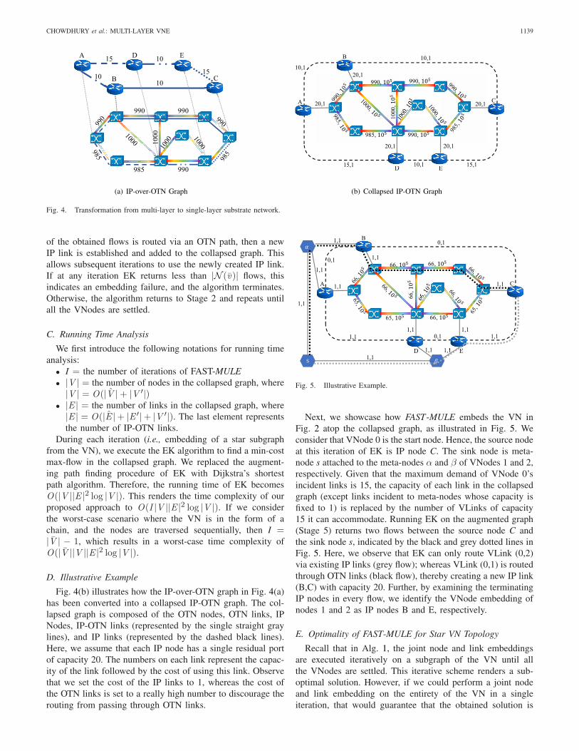
Fig. 4. Transformation from multi-layer to single-layer substrate network.
of the obtained flows is routed via an OTN path, then a newIP link is established and added to the collapsed graph. Thisallows subsequent iterations to use the newly created IP link.If at any iteration EK returns less than |N (v)| flows, thisindicates an embedding failure, and the algorithm terminates.Otherwise, the algorithm returns to Stage 2 and repeats untilall the VNodes are settled.
C. Running Time Analysis
We first introduce the following notations for running timeanalysis:
• I = the number of iterations of FAST-MULE• |V | = the number of nodes in the collapsed graph, where
|V | = O(|V | + |V ′|)• |E | = the number of links in the collapsed graph, where
|E | = O(|E |+ |E ′|+ |V ′|). The last element representsthe number of IP-OTN links.
During each iteration (i.e., embedding of a star subgraphfrom the VN), we execute the EK algorithm to find a min-costmax-flow in the collapsed graph. We replaced the augment-ing path finding procedure of EK with Dijkstra’s shortestpath algorithm. Therefore, the running time of EK becomesO(|V ||E |2 log |V |). This renders the time complexity of ourproposed approach to O(I |V ||E |2 log |V |). If we considerthe worst-case scenario where the VN is in the form of achain, and the nodes are traversed sequentially, then I =|V | − 1, which results in a worst-case time complexity ofO(|V ||V ||E |2 log |V |).
D. Illustrative Example
Fig. 4(b) illustrates how the IP-over-OTN graph in Fig. 4(a)has been converted into a collapsed IP-OTN graph. The col-lapsed graph is composed of the OTN nodes, OTN links, IPNodes, IP-OTN links (represented by the single straight graylines), and IP links (represented by the dashed black lines).Here, we assume that each IP node has a single residual portof capacity 20. The numbers on each link represent the capac-ity of the link followed by the cost of using this link. Observethat we set the cost of the IP links to 1, whereas the cost ofthe OTN links is set to a really high number to discourage therouting from passing through OTN links.
Fig. 5. Illustrative Example.
Next, we showcase how FAST-MULE embeds the VN inFig. 2 atop the collapsed graph, as illustrated in Fig. 5. Weconsider that VNode 0 is the start node. Hence, the source nodeat this iteration of EK is IP node C. The sink node is meta-node s attached to the meta-nodes α and β of VNodes 1 and 2,respectively. Given that the maximum demand of VNode 0’sincident links is 15, the capacity of each link in the collapsedgraph (except links incident to meta-nodes whose capacity isfixed to 1) is replaced by the number of VLinks of capacity15 it can accommodate. Running EK on the augmented graph(Stage 5) returns two flows between the source node C andthe sink node s, indicated by the black and grey dotted lines inFig. 5. Here, we observe that EK can only route VLink (0,2)via existing IP links (grey flow); whereas VLink (0,1) is routedthrough OTN links (black flow), thereby creating a new IP link(B,C) with capacity 20. Further, by examining the terminatingIP nodes in every flow, we identify the VNode embedding ofnodes 1 and 2 as IP nodes B and E, respectively.
E. Optimality of FAST-MULE for Star VN Topology
Recall that in Alg. 1, the joint node and link embeddingsare executed iteratively on a subgraph of the VN until allthe VNodes are settled. This iterative scheme renders a sub-optimal solution. However, if we could perform a joint nodeand link embedding on the entirety of the VN in a singleiteration, that would guarantee that the obtained solution is

1140 IEEE TRANSACTIONS ON NETWORK AND SERVICE MANAGEMENT, VOL. 15, NO. 3, SEPTEMBER 2018
indeed optimal. Such embedding is possible when all the nodesin the VN are only connected to a single node, and if the lat-ter is selected as the start node, i.e., the VN topology is astar. A star VN topology S(N) contains a center node u andN links connecting u to N leaf nodes {v1, v2, . . . vN }. In thesequel, we prove that Alg. 1 can find the optimal solution inpolynomial time when the VN request is a star topology (typ-ically used to support multi-cast services [4]) with identicalbandwidth demand on all VLinks.
Theorem 1: Given a star VN topology G = S (N ) withuniform bandwidth demand β for all VLinks, Alg. 1 obtainsthe optimal solution in polynomial time.
Proof: The optimal embedding of G , M∗, is the onewhere the VNodes are placed on the IP nodes that providethe lowest cost link embedding. The cost includes both thecost of provisioning new IP links and the cost of allocat-ing bandwidth for VLinks. We denote the cost of M∗ asθ∗ = β
∑Ni=1
∑u′v ′∈Puvi
Cu′v ′ , where Pu vi is the embed-ding path for VLink (u, vi ). Without loss of generality, weabstract a newly created IP link (u′, v′)’s cost as Cu′v ′ . LetM be the solution obtained by Alg. 1. For simplicity, weassume the central node u has exactly one IP node in itslocation constraint set. M consists of placing u on the IPnode in its location constraint set, v′, followed by runningEK from v′ to the sink node s. EK will return the min-costmax-flow from v′ to the sink node s. Given that the capac-ity of all the incident links to s are 1, the number of flowaugmenting paths will be at most the number of leaf nodesin G and exactly 1 unit of flow will be pushed througheach of these augmenting paths. Therefore, upon successfulembedding, EK will return N flow augmenting paths with min-imum cost θ. Now recall that the only way to push N flowstowards the sink is to traverse every meta-node once; whichentails the traversal of one node from each location constraintset. The traversed nodes represent the VNode embedding ofall the leaf nodes in S(N). Therefore, the flow augmentingpaths represent a valid embedding of S(N). We can charac-terize θ as, θ =
∑Ni=1
∑(u,v)∈Fi
Cuv × fuv , where Fi isthe i-th flow augmenting path and fuv is the flow pushedalong link (u, v) in the flow network constructed from thecollapsed graph. Note that, fuv = 1, therefore, the costbecomes, θ =
∑Ni=1
∑(u,v)∈Fi
Cuv . If we can prove that∑Ni=1
∑(u,v)∈Fi
Cuv =∑N
i=1
∑u′v ′∈Puvi
Cu′v ′ then ourproof is complete. Since θ∗ is the optimal objective value, let,∑N
i=1
∑(u,v)∈Fi
Cuv >∑N
i=1
∑u′v ′∈Puvi
Cu′v ′ . Then it
implies that if we pushed the flows along the paths⋃N
i=1 Pu vi(the newly created IP links can be expanded to a set of OTNlinks to match the paths in the collapsed graph), we wouldhave obtained a lower cost solution to min-cost max-flowproblem, which contradicts that θ is the minimum cost of ourmin-cost max-flow problem for the converted flow network.Therefore,
∑Ni=1
∑(u,v)∈Fi
Cuv =∑N
i=1
∑u′v ′∈Puvi
Cu′v ′ ,completing our proof.
If the central node, u , has more than one candidate node inits location constraint set, then running Alg. 1 |L(u)| times issufficient to obtain the lowest cost mapping solution, and therunning time of Alg. 1 still remains polynomial.
F. Parallel Implementation of FAST-MULE
Note that during the execution of stage 2 in FAST-MULE,i.e., during the extraction of star-subgraphs from the VN, werandomly chose a VNode as the center node of the extractedstar graph. Indeed, the order in which the VNodes are chosenfor star subgraph extraction has an impact on the performanceof the heuristic. Therefore, we propose to execute the heuristicfor a set of VNode orderings and choose the least cost onefrom the resulting solutions. Clearly, this means increasing theorder of complexity for FAST-MULE.
One way to consider different VNode ordering in FAST-MULE is to consider the different VNode orders in parallel,i.e., implement FAST-MULE as a multi-threaded program toutilize the multiple CPU cores on modern machines. Eachthread of execution computes a solution to MULE by takinga VNode ordering as an input. Since, one execution of FAST-MULE for one VNode ordering is independent of anotherexecution with a different VNode ordering, therefore, theycan be run in parallel without requiring any synchronizationbetween the threads. After the parallel executions finish, wecan choose the best embedding, i.e., the least cost embeddingamong all the parallel executions.
VI. EVALUATION RESULTS
We evaluate our proposed solutions for MULE through sim-ulations. Due to the lack of publicly available real world multi-layer network topologies, we resort to generating synthetictopologies with varying sizes for our performance evaluation.We first describe our simulation setup in Section VI-A and theevaluation metrics in Section VI-B. Then we present our eval-uation results based on the following two scenarios: (i) micro-benchmarking of FAST-MULE by comparing with the optimalsolution and to D-VNE [7], the state-of-the-art heuristicfor solving multi-layer VNE problem (Section VI-C), and(ii) steady-state analysis of the performance of FAST-MULEand comparison with that of D-VNE [7] (Section VI-D).For the micro-benchmarking scenario, we consider the VNrequests in isolation, assuming each VN request can be suc-cessfully embedded on the SN. Micro-benchmarking allows usto measure how resource efficient is FAST-MULE comparedto the optimal solution and to D-VNE [7]. In contrast, for thesteady-state scenario, we consider VN arrival and departureover a period of time and consider the possibility of failingto embed VN requests on the SN. The steady-state analysisgives insights on substrate resource utilization over a longerperiod of time.
A. Simulation Setup
1) Testbed: We have implemented OPT-MULE and FAST-MULE using IBM ILOG CPLEX 12.5 C++ libraries andJava, respectively. OPT-MULE was run on a machine with4×8 core 2.4Ghz Intel Xeon E5-4640 CPU and 512GB ofmemory, whereas, we used a machine with 2×8 core 2GhzIntel Xeon E5-2650 CPU and 256GB memory to evaluateFAST-MULE We used a home-grown discrete event simulatorto simulate the arrival and departure of VNs for the steadystate scenario.
CHOWDHURY et al.: MULTI-LAYER VNE 1141
2) Multi-Layer IP-Over-OTN Topology: As mentioned ear-lier, due to the lack of publicly available real multi-layernetwork topologies, we resorted to synthetically generating themulti-layer SN topologies. For the micro-benchmarking sce-nario, we generated OTNs by varying the size between 15–100nodes. For each OTN, we generated an IP topology with a nodecount of 60% of that of the OTN. Each node in the IP topologywas attached to exactly one node in the OTN topology. Forboth the OTN and the IP topologies, we set a link generationprobability to match their average node degree to known ISPtopologies [52]. For the steady state scenario, we generateda larger SN topology with a 150 node OTN and 90 node IPnetwork. Choice of such a size is based on the average size ofknown ISP networks found in [52]. The link generation prob-ability was again chosen to ensure node degrees are similarto known ISP topologies. For both scenarios, OTN links wereassigned a capacity of 100Gbps, while IP links were assigneda capacity randomly chosen between 10–20Gbps. Finally, weused a constrained shortest-path algorithm to map the input IPlinks over OTN paths.
3) VN Topology: For the micro-benchmarking scenario, wegenerated 20 VNs for each combination of IP and OTN, eachVN with 4–8 VNodes. For the steady state case, we variedthe size of the VN between 4–15 VNodes. For both scenar-ios, we set a 50% probability of having a link between everypair of VNodes. VLink capacities were randomly set between50%–100% of that of the IP links. For each VNode, we gen-erated a location constraint set by randomly selecting an IPnode and including all the IP nodes withing its 3-hop reach.For random graph generation (both the VN and the SN) weused Erdos – Renyi method [53].
We evaluated the arrival and departure of VNs in the steadystate scenario by simulating a Poisson process. We varied theVN arrival rate between 4 to 10 VNs per 100 time units,with a VN lifetime exponentially distributed with a mean of1000 time units. These chosen set of parameters conforms withthe ones used in [5], [20], and [26].
B. Evaluation Metrics
1) Cost Ratio: This is the ratio of costs obtained by twodifferent approaches for solving the same problem instance,where cost is computed using (14). Cost ratio measures therelative performance of two approaches.
2) Execution Time: The time required for an algorithm tosolve one instance of MULE.
3) Acceptance Ratio: The fraction of VN requests thathave been successfully embedded on the SN over all the VNrequests.
4) Utilization: The Utilization of an IP link is computed asthe ratio of total bandwidth allocated to the embedded VLinksto that IP links capacity
5) Embedding Path Length: The length of IP (or OTN) pathcorresponding to a VLink’s (or new IP link’s) embedding.
C. Micro-Benchmarking Results
We focus our micro-benchmarking on the following aspects:(i) cost comparison between FAST-MULE and OPT-MULE to
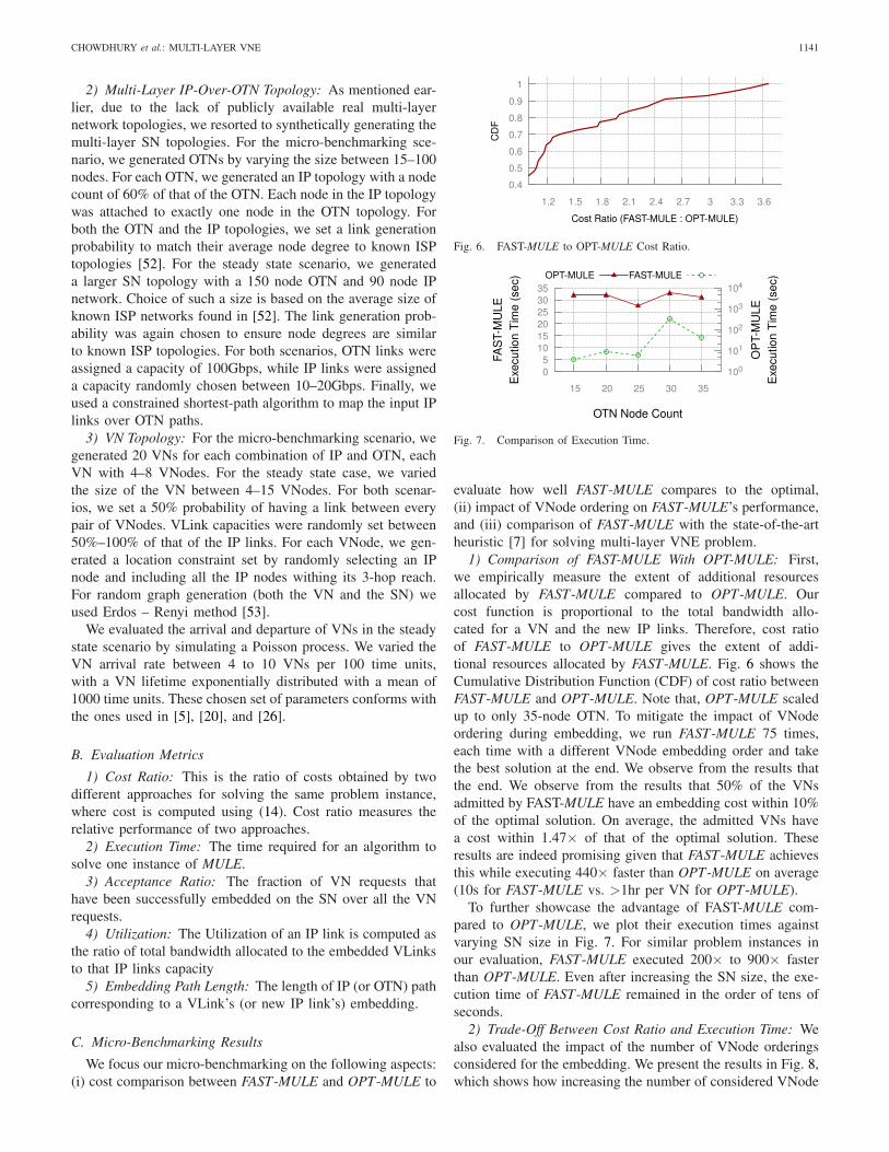
Fig. 6. FAST-MULE to OPT-MULE Cost Ratio.
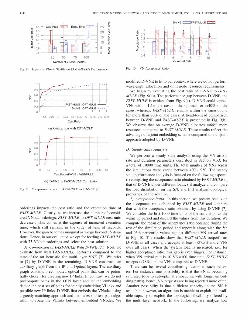
Fig. 7. Comparison of Execution Time.
evaluate how well FAST-MULE compares to the optimal,(ii) impact of VNode ordering on FAST-MULE’s performance,and (iii) comparison of FAST-MULE with the state-of-the-artheuristic [7] for solving multi-layer VNE problem.
1) Comparison of FAST-MULE With OPT-MULE: First,we empirically measure the extent of additional resourcesallocated by FAST-MULE compared to OPT-MULE. Ourcost function is proportional to the total bandwidth allo-cated for a VN and the new IP links. Therefore, cost ratioof FAST-MULE to OPT-MULE gives the extent of addi-tional resources allocated by FAST-MULE. Fig. 6 shows theCumulative Distribution Function (CDF) of cost ratio betweenFAST-MULE and OPT-MULE. Note that, OPT-MULE scaledup to only 35-node OTN. To mitigate the impact of VNodeordering during embedding, we run FAST-MULE 75 times,each time with a different VNode embedding order and takethe best solution at the end. We observe from the results thatthe end. We observe from the results that 50% of the VNsadmitted by FAST-MULE have an embedding cost within 10%of the optimal solution. On average, the admitted VNs havea cost within 1.47× of that of the optimal solution. Theseresults are indeed promising given that FAST-MULE achievesthis while executing 440× faster than OPT-MULE on average(10s for FAST-MULE vs. >1hr per VN for OPT-MULE).
To further showcase the advantage of FAST-MULE com-pared to OPT-MULE, we plot their execution times againstvarying SN size in Fig. 7. For similar problem instances inour evaluation, FAST-MULE executed 200× to 900× fasterthan OPT-MULE. Even after increasing the SN size, the exe-cution time of FAST-MULE remained in the order of tens ofseconds.
2) Trade-Off Between Cost Ratio and Execution Time: Wealso evaluated the impact of the number of VNode orderingsconsidered for the embedding. We present the results in Fig. 8,which shows how increasing the number of considered VNode
1142 IEEE TRANSACTIONS ON NETWORK AND SERVICE MANAGEMENT, VOL. 15, NO. 3, SEPTEMBER 2018
Fig. 8. Impact of VNode Shuffle on FAST-MULE’s Performance.
Fig. 9. Comparison between FAST-MULE and D-VNE [7].
orderings impacts the cost ratio and the execution time ofFAST-MULE. Clearly, as we increase the number of consid-ered VNode orderings, FAST-MULE to OPT-MULE cost ratiodecreases. This comes at the expense of increased executiontime, which still remains in the order of tens of seconds.However, the gain becomes marginal as we go beyond 75 itera-tions. Hence, in our evaluation we opt for feeding FAST-MULEwith 75 VNode orderings and select the best solution.
3) Comparison of FAST-MULE With D-VNE [7]: Now, weevaluate how well FAST-MULE performs compared to thestate-of-the art heuristic for multi-layer VNE [7]. We referto [7] by D-VNE in the remaining. D-VNE constructs anauxiliary graph from the IP and Optical layers. The auxiliarygraph contains precomputed optical paths that can be poten-tially chosen for creating new IP links. In contrast, we do notprecompute paths in the OTN layer and let the embeddingdecide the best set of paths for jointly embedding VLinks andpossible new IP links. D-VNE first embeds the VNodes usinga greedy matching approach and then uses shortest path algo-rithm to route the VLinks between embedded VNodes. We
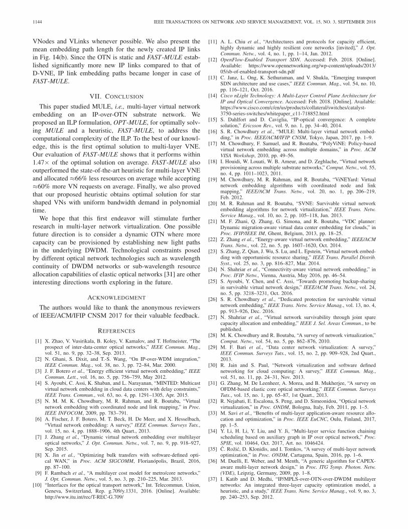
Fig. 10. VN Acceptance Ratio.
modified D-VNE to fit to our context where we do not performwavelength allocation and omit node resource requirements.
We begin by evaluating the cost ratio of D-VNE to OPT-MULE (Fig. 9(a)). The performance gap between D-VNE andFAST-MULE is evident from Fig. 9(a). D-VNE could embedVNs within 1.5× the cost of the optimal for ≈40% of thecases, whereas, FAST-MULE remains within the same boundfor more than 70% of the cases. A head-to-head comparisonbetween D-VNE and FAST-MULE is presented in Fig. 9(b).We observe that on average D-VNE allocates ≈66% moreresources compared to FAST-MULE. These results reflect theadvantage of a joint embedding scheme compared to a disjointapproach adopted by D-VNE.
D. Steady State Analysis
We perform a steady state analysis using the VN arrivalrate and duration parameters described in Section VI-A fora total of 10000 time units. The total number of VNs acrossthe simulations were varied between 400 - 950. The steadystate performance analysis is focused on the following aspects:(i) comparing the acceptance ratio obtained by FAST-MULE tothat of D-VNE under different loads, (ii) analyze and comparethe load distribution on the SN, and (iii) analyze topologicalproperties of the solution.
1) Acceptance Ratio: In this section, we present results onthe acceptance ratio obtained by FAST-MULE and comparethat with the acceptance ratio obtained by using D-VNE [7].We consider the first 1000 time units of the simulation as thewarm up period and discard the values from this duration. Wecompute the mean of the acceptance ratio obtained during therest of the simulation period and report it along with the 5thand 95th percentile values against different VN arrival ratesin Fig. 10. The results show that FAST-MULE outperformsD-VNE in all cases and accepts at least ≈37.5% more VNsover all cases. When the system load is increased, i.e., forhigher acceptance ratio, this gap is even bigger. For instance,when VN arrival rate is 10 VNs/100 time unit, FAST-MULEaccepts ≈78%× more VNs compared to D-VNE.
There can be several contributing factors to such behav-ior. For instance, one possibility is that the SN is becomingsaturated (due to sub-optimal embedding with longer embed-ding paths), hence, VN requests are being rejected more often.Another possibility is that sufficient capacity in the SN isavailable, however, an algorithm is unable to exploit the avail-able capacity or exploit the topological flexibility offered bythe multi-layer network. In the following, we analyze how

CHOWDHURY et al.: MULTI-LAYER VNE 1143
Fig. 11. Load Distribution at the IP Layer.
Fig. 12. Mean IP Link Utilization with Varying Load.
Fig. 13. Ratio of Newly Created IP Links (FAST-MULE : D-VNE) withVarying Load.
these algorithms distribute load over the substrate and howmuch they are able to exploit the topological flexibility togain further insight into the difference in acceptance ratio.
2) Load Distribution: We measure the utilization of IPlinks at each VN arrival and departure event. We presentthe mean IP link utilization for varying load (i.e., VN arrivalrate) in Fig. 12. One interesting observation is that, althoughD-VNE yields a lower acceptance ratio, it exhibited a highermean link utilization compared to FAST-MULE (≈10% more).However, this plot does not capture the variance in link utiliza-tion and does not say much about how the load is distributedover the IP links.
We present a further break down of IP link utilizationin Fig. 11. Specifically, where we present the CumulativeDistribution Function (CDF) mean, 5th percentile, and95th percentile link utilizations in Fig. 11(a), Fig. 11(b),and Fig. 11(c), respectively. The results for load distributionis also consistent with that from Fig. 12, i.e., at all the spec-trum of distribution D-VNE is exhibiting slightly higher linkutilization while yielding lower acceptance ratio.
Fig. 14. Mean Embedding Path Length.
Another aspect that can also be tributary to such behavioris the extent to which the algorithms are exploiting the topo-logical flexibility of multi-layer networks. After the end ofeach simulation we counted the total number of new IP linksthat were established by FAST-MULE and D-VNE, respec-tively, and present the ratio of these numbers in Fig. 13. Aswe can observe, FAST-MULE created more IP links comparedto D-VNE and hence was able to accept more VNs in the longrun. Because of the higher number of IP links, the graph diam-eter reduced and resulted in possibly shorter embedding paths,hence, lower utilization of individual links. Because of thejoint optimization approach, FAST-MULE was able to makebetter decisions regarding creation of new IP links and alsofor embedding paths, hence, the acceptance ratio and lowerlink utilization.
3) Topological Properties of the Solution: For each simula-tion setting, we computed the mean embedding path length forboth the VLinks and the newly created IP links and present theresult in Fig. 14. We observe from Fig. 14(a) that FAST-MULEembedded the VLinks on shorter paths (≈30%) compared toD-VNE. This is a combined effect of being able to create moreIP links on the long run as well as the joint embedding of
1144 IEEE TRANSACTIONS ON NETWORK AND SERVICE MANAGEMENT, VOL. 15, NO. 3, SEPTEMBER 2018
VNodes and VLinks whenever possible. We also present themean embedding path length for the newly created IP linksin Fig. 14(b). Since the OTN is static and FAST-MULE estab-lished significantly more new IP links compared to that ofD-VNE, IP link embedding paths became longer in case ofFAST-MULE.
VII. CONCLUSION
This paper studied MULE, i.e., multi-layer virtual networkembedding on an IP-over-OTN substrate network. Weproposed an ILP formulation, OPT-MULE, for optimally solv-ing MULE and a heuristic, FAST-MULE, to address thecomputational complexity of the ILP. To the best of our knowl-edge, this is the first optimal solution to multi-layer VNE.Our evaluation of FAST-MULE shows that it performs within1.47× of the optimal solution on average. FAST-MULE alsooutperformed the state-of-the-art heuristic for multi-layer VNEand allocated ≈66% less resources on average while accepting≈60% more VN requests on average. Finally, we also provedthat our proposed heuristic obtains optimal solution for starshaped VNs with uniform bandwidth demand in polynomialtime.
We hope that this first endeavor will stimulate furtherresearch in multi-layer network virtualization. One possiblefuture direction is to consider a dynamic OTN where morecapacity can be provisioned by establishing new light pathsin the underlying DWDM. Technological constraints posedby different optical network technologies such as wavelengthcontinuity of DWDM networks or sub-wavelength resourceallocation capabilities of elastic optical networks [31] are otherinteresting directions worth exploring in the future.
ACKNOWLEDGMENT
The authors would like to thank the anonymous reviewersof IEEE/ACM/IFIP CNSM 2017 for their valuable feedback.
REFERENCES
[1] X. Zhao, V. Vusirikala, B. Koley, V. Kamalov, and T. Hofmeister, “Theprospect of inter-data-center optical networks,” IEEE Commun. Mag.,vol. 51, no. 9, pp. 32–38, Sep. 2013.
[2] N. Ghani, S. Dixit, and T.-S. Wang, “On IP-over-WDM integration,”IEEE Commun. Mag., vol. 38, no. 3, pp. 72–84, Mar. 2000.
[3] J. F. Botero et al., “Energy efficient virtual network embedding,” IEEECommun. Lett., vol. 16, no. 5, pp. 756–759, May 2012.
[4] S. Ayoubi, C. Assi, K. Shaban, and L. Narayanan, “MINTED: Multicastvirtual network embedding in cloud data centers with delay constraints,”IEEE Trans. Commun., vol. 63, no. 4, pp. 1291–1305, Apr. 2015.
[5] N. M. M. K. Chowdhury, M. R. Rahman, and R. Boutaba, “Virtualnetwork embedding with coordinated node and link mapping,” in Proc.IEEE INFOCOM, 2009, pp. 783–791.
[6] A. Fischer, J. F. Botero, M. T. Beck, H. De Meer, and X. Hesselbach,“Virtual network embedding: A survey,” IEEE Commun. Surveys Tuts.,vol. 15, no. 4, pp. 1888–1906, 4th Quart., 2013.
[7] J. Zhang et al., “Dynamic virtual network embedding over multilayeroptical networks,” J. Opt. Commun. Netw., vol. 7, no. 9, pp. 918–927,Sep. 2015.
[8] X. Jin et al., “Optimizing bulk transfers with software-defined opti-cal WAN,” in Proc. ACM SIGCOMM, Florianópolis, Brazil, 2016,pp. 87–100.
[9] F. Rambach et al., “A multilayer cost model for metro/core networks,”J. Opt. Commun. Netw., vol. 5, no. 3, pp. 210–225, Mar. 2013.
[10] “Interfaces for the optical transport network,” Int. Telecommun. Union,Geneva, Switzerland, Rep. g.709/y.1331, 2016. [Online]. Available:http://www.itu.int/rec/T-REC-G.709/
[11] A. L. Chiu et al., “Architectures and protocols for capacity efficient,highly dynamic and highly resilient core networks [invited],” J. Opt.Commun. Netw., vol. 4, no. 1, pp. 1–14, Jan. 2012.
[12] OpenFlow-Enabled Transport SDN. Accessed: Feb. 2018. [Online].Available: https://www.opennetworking.org/wp-content/uploads/2013/05/sb-of-enabled-transport-sdn.pdf
[13] C. Janz, L. Ong, K. Sethuraman, and V. Shukla, “Emerging transportSDN architecture and use cases,” IEEE Commun. Mag., vol. 54, no. 10,pp. 116–121, Oct. 2016.
[14] Cisco nLight Technology: A Multi-Layer Control Plane Architecture forIP and Optical Convergence. Accessed: Feb. 2018. [Online]. Available:https://www.cisco.com/c/en/us/products/collateral/switches/catalyst-3750-series-switches/whitepaper_c11-718852.html
[15] S. Dahlfort and D. Caviglia, “IP-optical convergence: A completesolution,” Ericsson Rev., vol. 9, no. 1, pp. 34–40, 2014.
[16] S. R. Chowdhury et al., “MULE: Multi-layer virtual network embed-ding,” in Proc. IEEE/ACM/IFIP CNSM, Tokyo, Japan, 2017, pp. 1–9.
[17] M. Chowdhury, F. Samuel, and R. Boutaba, “PolyViNE: Policy-basedvirtual network embedding across multiple domains,” in Proc. ACMVISA Workshop, 2010, pp. 49–56.
[18] I. Houidi, W. Louati, W. B. Ameur, and D. Zeghlache, “Virtual networkprovisioning across multiple substrate networks,” Comput. Netw., vol. 55,no. 4, pp. 1011–1023, 2011.
[19] M. Chowdhury, M. R. Rahman, and R. Boutaba, “ViNEYard: Virtualnetwork embedding algorithms with coordinated node and linkmapping,” IEEE/ACM Trans. Netw., vol. 20, no. 1, pp. 206–219,Feb. 2012.
[20] M. R. Rahman and R. Boutaba, “SVNE: Survivable virtual networkembedding algorithms for network virtualization,” IEEE Trans. Netw.Service Manag., vol. 10, no. 2, pp. 105–118, Jun. 2013.
[21] M. F. Zhani, Q. Zhang, G. Simona, and R. Boutaba, “VDC planner:Dynamic migration-aware virtual data center embedding for clouds,” inProc. IFIP/IEEE IM, Ghent, Belgium, 2013, pp. 18–25.
[22] Z. Zhang et al., “Energy-aware virtual network embedding,” IEEE/ACMTrans. Netw., vol. 22, no. 5, pp. 1607–1620, Oct. 2014.
[23] S. Zhang, Z. Qian, J. Wu, S. Lu, and L. Epstein, “Virtual network embed-ding with opportunistic resource sharing,” IEEE Trans. Parallel Distrib.Syst., vol. 25, no. 3, pp. 816–827, Mar. 2014.
[24] N. Shahriar et al., “Connectivity-aware virtual network embedding,” inProc. IFIP Netw., Vienna, Austria, May 2016, pp. 46–54.
[25] S. Ayoubi, Y. Chen, and C. Assi, “Towards promoting backup-sharingin survivable virtual network design,” IEEE/ACM Trans. Netw., vol. 24,no. 5, pp. 3218–3231, Oct. 2016.
[26] S. R. Chowdhury et al., “Dedicated protection for survivable virtualnetwork embedding,” IEEE Trans. Netw. Service Manag., vol. 13, no. 4,pp. 913–926, Dec. 2016.
[27] N. Shahriar et al., “Virtual network survivability through joint sparecapacity allocation and embedding,” IEEE J. Sel. Areas Commun., to bepublished.
[28] M. K. Chowdhury and R. Boutaba, “A survey of network virtualization,”Comput. Netw., vol. 54, no. 5, pp. 862–876, 2010.
[29] M. F. Bari et al., “Data center network virtualization: A survey,”IEEE Commun. Surveys Tuts., vol. 15, no. 2, pp. 909–928, 2nd Quart.,2013.
[30] R. Jain and S. Paul, “Network virtualization and software definednetworking for cloud computing: A survey,” IEEE Commun. Mag.,vol. 51, no. 11, pp. 24–31, Nov. 2013.
[31] G. Zhang, M. De Leenheer, A. Morea, and B. Mukherjee, “A survey onOFDM-based elastic core optical networking,” IEEE Commun. SurveysTuts., vol. 15, no. 1, pp. 65–87, 1st Quart., 2013.
[32] R. Nejabati, E. Escalona, S. Peng, and D. Simeonidou, “Optical networkvirtualization,” in Proc. ONDM, Bologna, Italy, Feb. 2011, pp. 1–5.
[33] M. Savi et al., “Benefits of multi-layer application-aware resource allo-cation and optimization,” in Proc. IEEE EuCNC, Oulu, Finland, 2017,pp. 1–5.
[34] Y. Li, H. Li, Y. Liu, and Y. Ji, “Multi-layer service function chainingscheduling based on auxiliary graph in IP over optical network,” Proc.SPIE, vol. 10464, Oct. 2017, Art. no. 1046424.
[35] C. Rožic, D. Klonidis, and I. Tomkos, “A survey of multi-layer networkoptimization,” in Proc. ONDM, Cartagena, Spain, 2016, pp. 1–6.
[36] M. Duelli, E. Weber, and M. Menth, “A generic algorithm for CAPEX-aware multi-layer network design,” in Proc. ITG Symp. Photon. Netw.(VDE), Leipzig, Germany, 2009, pp. 1–8.
[37] I. Katib and D. Medhi, “IP/MPLS-over-OTN-over-DWDM multilayernetworks: An integrated three-layer capacity optimization model, aheuristic, and a study,” IEEE Trans. Netw. Service Manag., vol. 9, no. 3,pp. 240–253, Sep. 2012.

CHOWDHURY et al.: MULTI-LAYER VNE 1145
[38] C. Govardan et al., “A heuristic algorithm for network optimization ofOTN over DWDM network,” in Proc. IEEE ANTS, 2015, pp. 1–6.
[39] E. Palkopoulou, D. A. Schupke, and T. Bauschert, “Energy efficiencyand CAPEX minimization for backbone network planning: Is there atradeoff?” in Proc. IEEE ANTS, New Delhi, India, 2009, pp. 1–3.
[40] H. Zhang and A. Durresi, “Differentiated multi-layer survivability inIP/WDM networks,” in Proc. IEEE/IFIP NOMS, Florence, Italy, 2002,pp. 681–694.
[41] W. Bigos, B. Cousin, S. Gosselin, M. Le Foll, and H. Nakajima,“Survivable MPLS over optical transport networks: Cost and resourceusage analysis,” IEEE J. Sel. Areas Commun., vol. 25, no. 5,pp. 949–962, Jun. 2007.
[42] W. Lu, X. Yin, X. Cheng, and Z. Zhu, “On cost-efficient integratedmultilayer protection planning in IP-over-EONs,” J. Lightw. Technol.,vol. 36, no. 10, pp. 2037–2048, May 15, 2018.
[43] A. Alashaikh, D. Tipper, and T. Gomes, “Supporting differentiatedresilience classes in multilayer networks,” in Proc. IEEE DRCN, Paris,France, 2016, pp. 31–38.
[44] M. Tornatore, D. Lucerna, B. Mukherjee, and A. Pattavina, “Multilayerprotection with availability guarantees in optical WDM networks,” J.Netw. Syst. Manag., vol. 20, no. 1, pp. 34–55, 2012.
[45] O. Gerstel et al., “Multi-layer capacity planning for IP-optical networks,”IEEE Commun. Mag., vol. 52, no. 1, pp. 44–51, Jan. 2014.
[46] P. Demeester et al., “Resilience in multilayer networks,” IEEE Commun.Mag., vol. 37, no. 8, pp. 70–76, Aug. 1999.
[47] D. BianchiAn, G. Parthasarathy, and Y. Xu, “OTN system and methodfor supporting single-fiber bidirectional transmission of supervisorychannel light,” WO Patent WO2 015 127 780, Sep. 2015. [Online].Available: https://patents.google.com/patent/WO2015127780A1/en
[48] S. Chen et al., “Full-duplex bidirectional data transmission link usingtwisted lights multiplexing over 1.1-km orbital angular momentumfiber,” Sci. Rep., vol. 6, Nov. 2016, Art. no. 38181.
[49] Link Aggregation Control Protocol. Accessed: Feb. 2018. [Online].Available: http://www.ieee802.org/3/ad/public/mar99/seaman_1_0399.pdf
[50] Y. Dinitz, N. Garg, and M. X. Goemans, “On the single-sourceunsplittable flow problem,” in Proc. IEEE FOCS, 1998, pp. 290–299.
[51] J. Edmonds and R. M. Karp, “Theoretical improvements in algorith-mic efficiency for network flow problems,” J. ACM, vol. 19, no. 2,pp. 248–264, 1972.
[52] N. Spring, R. Mahajan, and D. Wetherall, “Measuring ISP topologieswith rocketfuel,” ACM SIGCOMM Comput. Commun. Rev., vol. 32,no. 4, pp. 133–145, 2002.
[53] P. Erdös and A. Rényi, “On random graphs, I,” PublicationesMathematicae, vol. 6, pp. 290–297, 1959.
Shihabur Rahman Chowdhury (S’13) receivedthe B.Sc. degree in computer science and engineer-ing from the Bangladesh University of Engineeringand Technology. He is currently pursuing the Ph.D.degree with the David R. Cheriton School ofComputer Science, University of Waterloo. Hisresearch interests include virtualization and soft-warization of computer networks. He was a recipientof several scholarships and awards, including theBest Paper Award at IEEE/ACM/IFIP CNSM 2017,the MITACS Globalink Research Award, the Ontario
Graduate Scholarship, President’s Graduate Scholarship, GoBell Scholarship,and Graduate Excellence Scholarship in Computer Science with the Universityof Waterloo.
Sara Ayoubi received the Ph.D. degree in infor-mation and systems engineering from ConcordiaUniversity. In 2016, she was a Post-DoctoralFellow with the Cheriton School of ComputerScience, University of Waterloo. She is currently aPost-Doctoral Fellow with Inria, Paris. She is theCo-Founder of the Montreal Operations ResearchStudent Chapter. Her research interests are in thefields of operations research, networks, and com-puter systems. She was a recipient of several awards,including the Dissertation Prize for Engineering and
Computer Science and the Best paper Award at IEEE CloudNet 2015. Shewas a co-recipient of the Best Paper Award at IEEE/IFIP CNSM 2017, andselected as a rising star in EECS in 2017.
Reaz Ahmed received the B.Sc. and M.Sc. degreesin computer science from the Bangladesh Universityof Engineering and Technology in 2000 and 2002,respectively, and the Ph.D. degree in computer sci-ence from the University of Waterloo in 2007. Hisresearch interests include future Internet architec-tures, information-centric networks, network virtu-alization, and content sharing peer-to-peer networkswith focus on search flexibility, efficiency, androbustness. He was a recipient of the IEEEFred W. Ellersick Award in 2008.
Nashid Shahriar (S’16) received the B.Sc. andM.Sc. degrees in computer science and engineeringfrom the Bangladesh University of Engineering andTechnology in 2009 and 2011, respectively. He iscurrently pursuing the Ph.D. degree with the Schoolof Computer Science, University of Waterloo. Hisresearch interests include network virtualization, 5Gnetworks, and network reliability. He was a recip-ient of Ontario Graduate Scholarship, President’sGraduate Scholarship, and David R. CheritonGraduate Scholarship with the Universityof Waterloo.
Raouf Boutaba (F’12) received the M.Sc. and Ph.D.degrees in computer science from University Pierre& Marie Curie, Paris, in 1990 and 1994, respec-tively. He is currently a Professor of computerscience with the University of Waterloo. His researchinterests include resource and service managementin networks and distributed systems. He was arecipient of several best paper awards and recogni-tions, including the Premiers Research ExcellenceAward, the IEEE ComSoc Hal Sobol Award, theFred W. Ellersick Award, the Joe LociCero Award,
the Dan Stokesbury Award, the Salah Aidarous Award, and the IEEE CanadaMcNaughton Gold Medal. He was the Founding Editor-in-Chief of the IEEETRANSACTIONS ON NETWORK AND SERVICE MANAGEMENT from 2007 to2010 and on the editorial boards of other journals. He is a fellow of theEngineering Institute of Canada and the Canadian Academy of Engineering.
Jeebak Mitra received the M.A.Sc. and Ph.D.degrees in electrical engineering from the Universityof British Columbia in 2005 and 2010, respec-tively. From 2010 to 2011, he was a Senior SystemEngineer with Riot Micro, leading the system leveldesign for a local thermal equilibrium baseband.From 2011 to 2012, he was a Team Leader forphysical layer DSP design with BLINQ Networks,Ottawa, focusing on small cell backhaul products.Since 2013, he has been a Senior Staff Engineer withthe Huawei Technologies Canada Research Center,
Ottawa, in the areas of algorithm design and implementation for coherent high-speed optical transceivers and flexible optical networks. His research interestslie in the area of high-performance communication systems design focusingon optical and wireless networks. He was a recipient of the Best StudentPaper Award at the IEEE Canadian Conference in Electrical and ComputerEngineering 2009. He was a co-recipient of the Best Paper Award at CNSM2017.
Liu Liu received the M.Sc. and Ph.D. degrees in communication and infor-mation systems from the University of Electronic Science and Technology ofChina in 2011 and 2015, respectively. He was a Visiting Scholar in computerscience and engineering with the State University of New York at Buffalofrom 2012 to 2014. He joined Huawei as a Research Engineer in 2015. Hisresearch interests focus on network planning and optimization, uncertaintyoptimization, approximation algorithms, and cloud computing.