multi-instrument type miq96-2
TRANSCRIPT

DEIF A/S Tel.: (+45) 9614 9614 Frisenborgvej 33, DK-7800 Skive Fax: (+45) 9614 9615 Denmark E-mail: [email protected]
User’s Manual
Multi-instrument type MIQ96-2
4189320011B (UK)
• All 1- or 3-phase AC measurements (RMS) in one unit:
- URMS, IRMS, f - P, Q, S, PF (cos ϕ) - kWh, kvarh, kVA - MD, THD
• Programmable CT and VT ratio • Programmable connections 1W, 1W3, 2W3, 1W4, 3W4 • 2 outputs for kWh export, kvarh export or limit switch • Serial output
DE
IF A
/S

Page 2 of 48 Tel.: (+45) 9614 9614 • Fax: (+45) 9614 9615 • E-mail: [email protected]
List of contents
1. Warnings, regular information and remarks referring to CE-marking ............. 3 2. Application and description of function ............................................................. 3 3. Options.................................................................................................................. 4 4. Valid measurements............................................................................................. 4 5. Measured parameters .......................................................................................... 6 6. Display and key-pads........................................................................................... 7 7. Menus.................................................................................................................... 8 7.1 Display of measuring quantities for connection 3W4 (4u), 1W4 (4b), 2W3 (3u)
and 1W3 (3b) ................................................................................................................ 8 7.2 Display of measuring quantities for connection 1W (1b).............................................. 12 8. Watt and var meters ........................................................................................... 15 8.1 Displaying of measuring energy .................................................................................. 15 8.2 Measuring of energy.................................................................................................... 16 9. Maximum demands (MD) ................................................................................... 18 9.1 Display of maximum demands (MD) ........................................................................... 18 9.2 Thermal demand......................................................................................................... 19 9.3 Fixed window .............................................................................................................. 20 9.4 Sliding window ............................................................................................................ 21 10. Display of current............................................................................................... 22 10.1 Current THD (total harmonic distortion)....................................................................... 22 11. Display of voltage............................................................................................... 23 11.1 Voltage THD (total harmonic distortion)....................................................................... 24 12. Display of active, reactive and apparent power ............................................... 24 13. Display of power factor PF (cos ϕ) and frequency........................................... 26 14. Display of real time clock .................................................................................. 26 15. Display of the menu “Setting”........................................................................... 27 16. Installation .......................................................................................................... 28 16.1 Mechanical installation ................................................................................................ 28 16.2 Electrical installation.................................................................................................... 29 16.3 Connection for aux. supply .......................................................................................... 31 16.4 RS485 Modbus .......................................................................................................... 31 16.5 Connection for relay outputs........................................................................................ 32 17. Setting................................................................................................................. 33 17.1 Setting of language ..................................................................................................... 33 17.2 Other settings.............................................................................................................. 35 17.3 Connection.................................................................................................................. 36 17.4 Communication (option) .............................................................................................. 38 17.5 Maximum demand (MD) calculations .......................................................................... 39 17.6 Reset MD.................................................................................................................... 40 17.7 Pulse output (setting of parameters of impulse outputs) (option)................................. 42 17.8 Clock (setting of real time clock) ................................................................................. 43 17.9 Display (setting of display parameters)........................................................................ 44 17.10 Language (setting of language)................................................................................... 44 18. Password ............................................................................................................ 45 19. Battery replacement ........................................................................................... 47 19.1 Instructions for replacement ........................................................................................ 48

User’s Manual, multi-instrument MIQ96-2
4189320011B (UK)
1. Warnings, regular information and remarks referring to CE-marking In this manual installations and working instructions for the multi-instrument MIQ96-2 are found. Installation as well as use of the MIQ96-2 will involve working with dangerous currents and voltages. Professionals must handle these areas. DEIF does not take on responsibility for the use and installation. If any doubt comes up concerning the installation or use of the system, on which the MIQ96-2 is to be used for measurement, the person responsible for the power installation should be contacted. The MIQ96-2 is CE-marked according to the EMC-directive for housing and light industry, which normally covers the most common use of the multi-instrument. Important: CTs must be short-circuited, before the wires are moved from terminals
on the multi-instrument. The delivery contains: - Multi-instrument MIQ96-2 - User’s manuals
2. Application and description of function The MIQ96-2 multi-instrument is a microprocessor-based unit for measurement of all electrical values in a 1- or 3-phase grid. Application of this unit is possible in all installations where these parameters are to be measured. All measured values are shown on the built-in display. Moreover the measurements can be transmitted as digital output and RS485 (see options). The MIQ96-2 can replace many analogue instruments in installations for measuring of electrical values and can be used as a conventional instrument and/or as a unit for transmitting values by the serial communication to a remote control base. Also the digital outputs can be connected to a local control system. All kinds of grids can be connected to the multi-instrument. Both with and without neutral - as well as balanced and unbalanced load. The unit contains all necessary loops for measurements and all values are displayed on an LCD. Information is presented in clear text and shown as actual values. Characteristic of the MIQ96-2 is the flexible set-up for different grid connections, CTs, VTs, languages et cetera, which ensures the user an easy adaptation of the unit to the wanted application. The set-up parameters and the reset of counters and peak values can be protected by passwords.

Page 4 of 48 Tel.: (+45) 9614 9614 • Fax: (+45) 9614 9615 • E-mail: [email protected]
3. Options Option 1: The RS485 remote control of all values and possible changes of set-
up, reset of counters and peak values. The MIQ96-2 implements a subset of the AEG Modicon Modbus RTU
serial communications standard. Serial Interface Manual and free utility software can be downloaded
from DEIF’s homepage www.deif.com. Option 2: Relay output for kWh import and kvarh import.
4. Valid measurements The MIQ96-2 is supplied configured in 3-phase 4-wire unbalanced. This variation may be reconfigured via the front panel or remote communications as follows: • 1b (1W) Single phase connection. • 3b (1W3) Three-phase three-wire connection with balanced load. • 3u (2W3) Three phase three-wire connection with unbalanced load. • 4b (1W4) Three-phase four-wire connection with balanced load. • 4u (3W4) Three-phase four-wire connection with unbalanced load. Also see the external wiring diagram section 16.2 page 29.
Parameter Connection type
1W 1W3 1W4 3W4 2W3
U1 • • •
U2 • •
U3 • •
U • • •
U12 • • • •
U23 • • • •
U31 • • • •
ΔU • • • •
ϕ12 • • • •
ϕ23 • • • •
ϕ31 • • • •
f • • • • •
I1 • • • • •
I2 • •
I3 • •

User’s Manual, multi-instrument MIQ96-2
4189320011B (UK)
Parameter Connection type
1W 1W3 1W4 3W4 2W3
It • • • • •
In •
P1 • • •
P2 • •
P3 • •
Pt • • • • •
cosϕ1 • • •
cosϕ2 • •
cosϕ3 • •
cosϕt • • • • •
Q1 • • •
Q2 • •
Q3 • •
Qt • • • • •
S1 • • •
S2 • •
S3 • •
St • • • • •
THD (U1) • • •
THD (U2) • •
THD (U3) • •
THD (U12) • • • •
THD (U23) • • • •
THD (U31) • • • •
THD (I1) • • • • •
THD (I2) • •
THD (I3) • •

Page 6 of 48 Tel.: (+45) 9614 9614 • Fax: (+45) 9614 9615 • E-mail: [email protected]
5. Measured parameters
Instantaneous measurements Parameters
Phase voltages U1, U2, U3
Average phase voltage U
Line voltages U12, U23, U31
Average line voltage ΔU
Angle between phases ϕ12, ϕ23, ϕ31
Current I1, I2, I3, It
Neutral current In
Active power P1, P2, P3, Pt
Reactive power Q1, Q2, Q3, Qt
Apparent power S1, S2, S3, St
Power factor cosϕ1, cosϕ2, cosϕ3, cosϕt
THD (total harmonic distortion) THD (I1, I2, I3, U1, U2, U3, U12,
U23, U31)
Frequency f
Integrated / maximum demands
Maximum demand It, Pt, Qt, St
Energy Wht, varht

User’s Manual, multi-instrument MIQ96-2
4189320011B (UK)
6. Display and key-pads The graphic LCD with yellow/green backlight is used for presentation of measured values and for displaying of the chosen function during set-up.
Up arrow key. Up through the main menus. + increases a value in the menu ”Setting”. Down arrow key. Down through the main menus. - decreases a value in the menu ”Setting”. Left arrow key. Left through the sub-menus. ”Exit” - skip of action by key-in or by changing in the menu ”Setting”. Right arrow key. Right through the sub-menus. ”Enter” - accept of changes in the menu ”Setting” or reset of counters and peak values.
EXIT ENTER
961.40263.89996.95
TOTAL
TOTAL
TOTAL

Page 8 of 48 Tel.: (+45) 9614 9614 • Fax: (+45) 9614 9615 • E-mail: [email protected]
7. Menus 7.1 Display of measuring quantities for connection 3W4 (4u), 1W4 (4b), 2W3 (3u) and 1W3 (3b)
The following displays appear at 3W4 (4u) connection. Displays for other connections are alike except from 1W (1b). Arrows between displays indicate which display occurs on the instrument when the corresponding key is pressed. If the password function is deactivated, the display for entering of password will not appear and access will be obtained directly.
43
43
ENTER PASSWORD: ****
56 56 56
43
43
43
56 56 56
43
43
56 56 56

User’s Manual, multi-instrument MIQ96-2
4189320011B (UK)

Page 10 of 48 Tel.: (+45) 9614 9614 • Fax: (+45) 9614 9615 • E-mail: [email protected]
43
43
43
56 56 56
43
43
56 56 56
43
43
43
56 56
43
56

User’s Manual, multi-instrument MIQ96-2
4189320011B (UK)
56 SETTING

Page 12 of 48 Tel.: (+45) 9614 9614 • Fax: (+45) 9614 9615 • E-mail: [email protected]
7.2 Display of measuring quantities for connection 1W (1b)
The following displays appear.
43
43
ENTER PASSWORD: ****
56
43
43
43
56
56
56

User’s Manual, multi-instrument MIQ96-2
4189320011B (UK)
56
56
56
56


User’s Manual, multi-instrument MIQ96-2
4189320011B (UK)
8. Watt and var meters 8.1 Displaying of measuring energy
Pictures of the measured energy are identical for all kinds of grid connections. Please notice that an indicator is flashing just to the right of the counter number when the counter is active.
43
43
ENTER PASSWORD: ****
To reset the energy value it is necessary to enter a password of level L1 or L2. When the password is entered, the following is displayed.
56
With the 56 keys the values of the energy, which will be reset, are selected. The
energy value is reset when the 4 key is pressed for five seconds. In the meantime a count-down of 5 seconds is made. After five seconds the picture of exports kWh and kvarh is displayed again, and the chosen counter is reset.
Please notice that all 4 counters can be reset simultaneously, if the 4 key is pressed
before using the 56 keys.
If the 4 key is released before the expiration of 5 seconds, the energy value is not reset. The resetting procedure is equal for all data resetting in the multi-instrument.

Page 16 of 48 Tel.: (+45) 9614 9614 • Fax: (+45) 9614 9615 • E-mail: [email protected]
8.2 Measuring of energy
In the figure below a 3W4 (4u) connection is shown to illustrate the direction of energy according to the 4 counters for kWh and kvarh. The direction of energy is identical for all other connections.
The consideration of import and export of energy.
KL
LK
KL3
1
46
97
11
8
5
2
13
14
15161718
192021
L1
L2
L3
N
K L
LK
LK
CT1 CT3
CT2
u
v v
u u
v
N
VVV
U U U N
Generator Consumer
Import
Export

User’s Manual, multi-instrument MIQ96-2
4189320011B (UK)
var Export
var Import
Watt Import
Watt Export
Export kWh counter 1 Export kvarh counter 2 Inductive 0 ≤ PF ≤ 1
Export kvarh counter 2 Import kWh counter 3 Inductive -1 ≤ PF ≤ 0
Import kWh counter 3 Import kvarh counter 4 Capacitive -1 ≤ PF ≤ 0
Export kWh counter 1 Import kvarh counter 4 Capacitive 0 ≤ PF ≤ 1
Direction of power
The function of the 4 counters, according to the displacement between voltage and current, is illustrated in the figure below. The MIQ96-2 has 2 relay outputs (see section 16.5 page 32), relay output 1 is corresponding to counter 3 (export kWh) and relay output 2 is corresponding to counter 4 (export kvarh). Change of this set-up can only be done through communication. Note: As default counters 1 and 2 are set to import, and counters 3 and 4 are set to export (different from the example).
4 3
2. 1. 3. 4.

Page 18 of 48 Tel.: (+45) 9614 9614 • Fax: (+45) 9614 9615 • E-mail: [email protected]
9. Maximum demands (MD) 9.1 Display of maximum demands (MD)
The MIQ96-2 provides demand values from a variety of average demand values (Thermal/bimetal instrument, Fixed window and Sliding window) for the following electrical parameters: Total active power (Pt) Sum of phase currents (It) Total reactive power (Qt) Total apparent power (St) Maximum demands The MIQ96-2 displays the present or “dynamic” maximum demand (value below “PRESENT MD”). The MIQ96-2 also stores the maximum demand value since last reset and its corresponding time stamp, visible either from the MIQ96-2 display or remote communications link (value below “MD at DD.MM HH:MM”). Only one of the following modes 1) Thermal, 2) Fixed window or 3) Sliding window can be active at a time. Set-up – see the menu “Settings” → ”Maximum demands” section 17.5 page 39.
43
43
43
43
Time into period 3 of 15 min.

User’s Manual, multi-instrument MIQ96-2
4189320011B (UK)
9.2 Thermal demand
The thermal demand option will provide an exponential thermal characteristic, based on the bimetal element principle. Maximum demand and the time of its occurrence are stored in the unit. The period (Time C.) can be set in the range 1 to 255 minutes. When “Thermal demand” mode is used, “Time into period” is not displayed.
THERMAL DEMAND
Time
W, A
AC
, var
or
VA
Present MD MD peak Input
Time C.

Page 20 of 48 Tel.: (+45) 9614 9614 • Fax: (+45) 9614 9615 • E-mail: [email protected]
9.3 Fixed window
The fixed interval mode calculates an average demand value over a fixed time period. The period (Time C.) can be set in the range 1 to 255 minutes. “Time into period” will be active and show the remaining time of a period until present MD and MD peak will be updated next. When Pt, It, Qt, St displays have been updated, a new time period starts and a new average demand is measured for the next period. Display “Time into period” shows 0 of xx min. Example: Mode: Fixed window Time C.: 8 min. Present MD and MD peak: Reset at time 0 min.
FIXED INTERVAL
1 2 3 4 5 6 7 8 9 10 11 12 13 14 15 16 17 18 19 20
Min.
W, A
AC
, var
or
VA
Present MD MD peak Input
Time C.

User’s Manual, multi-instrument MIQ96-2
4189320011B (UK)
9.4 Sliding window
The sliding window technique allows the user to divide the time period into a number of sub-periods. The average demand value over the demand total period is displayed, however, after the initial demand period has expired, the demand value will be updated by the addition of a further sub-period, thus creating a “sliding window” measurement. The number of sub-periods can be set from 2 to 15. The sub-period (Time C.) can be set in the range 1 to 255 minutes. Example: A total period is 8 minutes (consisting of 4 sub-periods of 2 minutes duration). The present MD and MD peak are reset at time 0 min. “Time into period” will consist of 2 minutes and make an update of present MD and MD peak every second minute. After the first 4 sub-periods (1 total period) have expired, a new window will be added and the oldest window will be deleted, thus creating a sliding window. This will always give an average demand value for the last 4 sub-periods.
SLIDING WINDOWS4 periods of 2 min.
1 2 3 4 5 6 7 8 9 10 11 12 13 14 15 16 17 18 19 20
Min.
W, A
AC
, var
or
VA
Present MD MD peak Input
Time C.
4 per. of Time C.

Page 22 of 48 Tel.: (+45) 9614 9614 • Fax: (+45) 9614 9615 • E-mail: [email protected]
N = ,
i
I
2n
N
=1nRMS
∑
10. Display of current The MIQ96-2 measures the true RMS value of the phase currents (I1, I2, I3) connected to the unit. The neutral current (In), average current (Ia) and the sum of all phase currents (It) are calculated from the three phase currents. The available phase currents, neutral current and average current can be viewed on the display or via the remote communications link while the sum of all phase currents is visible only via the remote communications link.
43
43
10.1 Current THD (total harmonic distortion)
The THD is calculated for phase currents. It is expressed as a percentage of harmonics due to fundamental frequency. The multi-instrument uses a true RMS (Root Mean Square) measurement technique which provides accurate measurement with harmonics present up to the 15th harmonic.
%%1001
2
2
THDI
Inn =•∑
∞
=
N is the number of sampled values within a period and in is the sampled value. N is 64 for the MIQ96-2.

User’s Manual, multi-instrument MIQ96-2
4189320011B (UK)
11. Display of voltage All connections of the MIQ96-2, except in the 3-wire mode (1W3 and 2W3), measure the true RMS value of the phase voltages (U1, U2, U3) connected to the unit (only U1 for 1W connection).
The three line voltages (U12, U23, U31), average phase voltage ( U ) and average line voltage ( ΔU ) are calculated from these measured parameters.
Calculation of line voltage: xyyxyxxy UUUUU ϕcos222 −+=
For 3-phase 3-wire balanced systems (1W3) and 3-phase 3-wire unbalanced system (2W3), the MIQ96-2 creates a virtual neutral internally. The available phase, line and average voltages can be viewed on the MIQ96-2 display or via the remote communications link. Angles between phases indicate the angles between the vectors of phase voltages. A positive mark indicates correct phase sequence, while a negative mark indicates an opposite phase sequence of the measured system.
43
43
43
56 56 56
43
43

Page 24 of 48 Tel.: (+45) 9614 9614 • Fax: (+45) 9614 9615 • E-mail: [email protected]
%%1001
2
2
THDU
Unn =•∑
∞
=
Ni u = P nn
N
=1n
×∑
11.1 Voltage THD (total harmonic distortion)
The THD is calculated for phase voltages and line voltages. It is expressed as a percentage of harmonics due to fundamental frequency. The MIQ96-2 uses a true RMS (Root Mean Square) measurement technique which provides accurate measurement with harmonics present up to the 15th harmonic.
12. Display of active, reactive and apparent power The MIQ96-2 provides accurate measurement of active (P1, P2, P3, Pt), reactive (Q1, Q2, Q3, Qt) and apparent power (S1, S2, S3, St). Active power: Calculation of P1, 2, 3:
Calculation of Pt: Pt = P1+ P2+ P3 Reactive power:
Calculation of Q1, 2, 3: 22)( PUIQ −=
Calculation of Qt: Qt = Q1+ Q2+ Q3 Apparent power:
Calculation of S1, 2, 3: 2
12
11 QP +=S
Calculation of St: 22 QP ttSt +=
N (64) is the number of samples, and un and in are sampled values within 1 period.

User’s Manual, multi-instrument MIQ96-2
4189320011B (UK)
For four-wire systems (1W4, 3W4) the powers are calculated both for each phase separately and as a total. For three-wire (1W3, 2W3) and single phase systems (1W) only total power values are measured. When displaying active power, a positive sign indicates export power while a negative sign indicates import power (see section 8.2 page 16). When displaying reactive power, a coil symbol indicates an inductive load while a capacitor symbol indicates a capacitive load (see section 13 page 26). All the available power parameters can be viewed using either the MIQ96-2 display or the remote communications link.
43
43
43

Page 26 of 48 Tel.: (+45) 9614 9614 • Fax: (+45) 9614 9615 • E-mail: [email protected]
13. Display of power factor PF (cos ϕ) and frequency The power factor is calculated as a quotient of active and apparent power for each phase separately (cosϕ1, cosϕ2, cosϕ3) and as a total (cosϕt). Calculation of cosϕ1: cosϕ1= P1/S1 Calculation of cosϕt: cosϕt= Pt/St Cosϕ1, cosϕ2, cosϕ3 for each phase are only displayed in a 3W4 connection and set-up. A positive sign and a coil symbol indicate an inductive load while a negative sign and a capacitor symbol indicate a capacitive load (see section 8.2 page 16). All available power factor parameters can be read from the display or via the remote communications link.
43
The system frequency is calculated from the time period of the measured voltage and can be viewed both from the display and the remote communications link.
14. Display of real time clock The MIQ96-2 is provided with a built-in real time clock. It is intended for registration of time of the occurrence of MDs, and for synchronisation of the time interval. On delivery from DEIF, the MIQ96-2 is set up with CET time (winter time). Switching from winter time to summer time must be done manually in the menu “Setting”.
User’s Manual, multi-instrument MIQ96-2
4189320011B (UK)
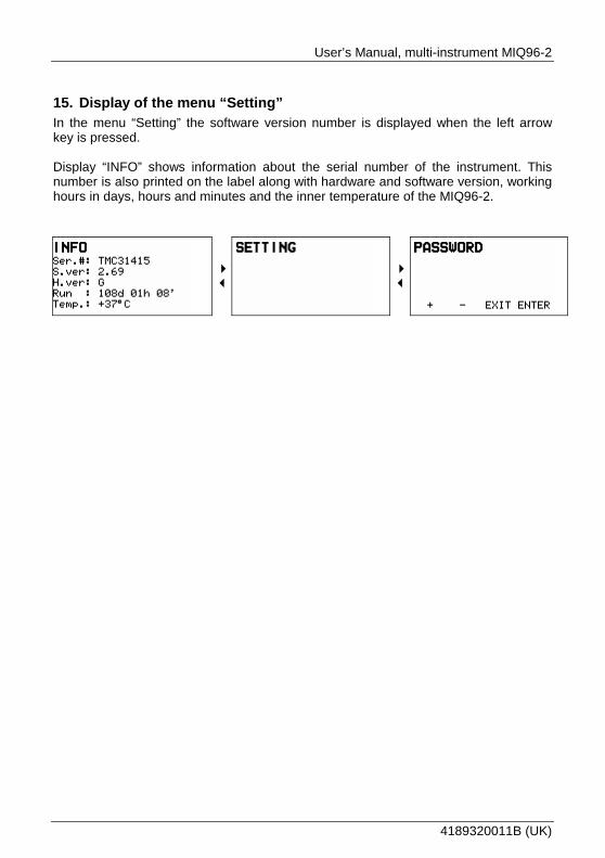
15. Display of the menu “Setting” In the menu “Setting” the software version number is displayed when the left arrow key is pressed. Display “INFO” shows information about the serial number of the instrument. This number is also printed on the label along with hardware and software version, working hours in days, hours and minutes and the inner temperature of the MIQ96-2.
43
43

Page 28 of 48 Tel.: (+45) 9614 9614 • Fax: (+45) 9614 9615 • E-mail: [email protected]
16. Installation In this section the line of general directions for the installation of the MIQ96-2 are indicated. Installation as well as use of the MIQ96-2 will involve working with dangerous currents and voltages. Professionals must handle these areas. DEIF does not take on responsibility for the use and installation. If any doubt comes up concerning the installation or use of the system, on which the MIQ96-2 is to be used for measurement, the person responsible for the power installation should be contacted. Before commissioning: Check voltage and revolving field. These must be correct. Warning: Missing or wrong voltage and other input errors might
cause malfunction and damage on the MIQ96-2. 16.1 Mechanical installation
Dimensions (in mm).
Protection lid for terminals Weight: Approx. 0.65 kg Panel cut-out: 92 x 92 mm + 0.8
1. Remove the 4 screws before inserting the instrument in the panel cut-out,
and then replace and tighten the screws until the instrument is fastened in the panel.
2. Remove the folio protection from the display.
Figure 16.1
16
19
20
21
17
18
3
1564
1
8
13
14
5
2
L 9
LK
K 7L
11
K
5.5Max. 40mm
43.0
92.
0±0.
8
96.0
90.0
53.0 28.0
90.0

User’s Manual, multi-instrument MIQ96-2
4189320011B (UK)
16.2 Electrical installation
Connection for measuring voltage and measuring current:
3. Choose one of the connections from the figures below and make the connection according to this for input voltage and input current.
Figure 16.2.1 1W connection (1b)
Figure 16.2.2 1W3 connection (3b)
Figure 16.2.3 2W3 connection (3u)
KL
LK
KL3
1
46
97
11
8
5
2
13
14
15161718
192021
L1K L
CT1 CT3
CT2
u
V
v
N
KL
LK
KL3
1
46
97
11
8
5
2
13
14
15161718
192021
L1
L2
L3
K L
CT1 CT3
CT2
VU
u v u
V
v
KL
LK
KL3
1
46
97
11
8
5
2
13
14
15161718
192021
L1
L2
L3
K L
LK
CT1 CT3
CT2
VU
u v u
V
v

Page 30 of 48 Tel.: (+45) 9614 9614 • Fax: (+45) 9614 9615 • E-mail: [email protected]
Figure 16.2.4 1W4 connection (4b)
Figure 16.2.5 3W4 connection (4u)
KL
LK
KL3
1
46
97
11
8
5
2
13
14
15161718
192021
L1
L2
L3
K L
CT1 CT3
CT2
V
V
N
KL
LK
KL3
1
46
97
11
8
5
2
13
14
15161718
192021
L1
L2
L3
N
K L
LK
LK
CT1 CT3
CT2
u
v v
u u
v
N
VVV
U U U N

User’s Manual, multi-instrument MIQ96-2
4189320011B (UK)
16.3 Connection for aux. supply
4. Make the connection for aux. supply to terminals 13 and 14.
16.4 RS485 Modbus
5. Make the connection for communication RS485 as shown in figure 16.4 below.
MIQ96-2 add. 002 MIQ96-2 add. 003 MIQ96-2 add. 004
6. Screened twisted pair must be used (min. 0.5 mm2). 7. Max. 32 multi-instruments in one string.
For RS485 communications the PC will require either an internal RS485 communications port or an external RS232/RS485 interface. In both cases the device must provide automatic RS485 data flow control. The maximum connection length is 1000 metres. Conductors A and B should be terminated with a 120Ω terminating resistor at the end of a string. RS485 connections:
MIQ96-2 RS485
A DATA +
C GND
B DATA – Note: It is recommended only to connect terminal C (GND), if solely MIQ96-2s are connected. In other situations, leave the terminal C open.
Figure 16.4
Other units

Page 32 of 48 Tel.: (+45) 9614 9614 • Fax: (+45) 9614 9615 • E-mail: [email protected]
16.5 Connection for relay outputs
Output 1: Potential free relay for kWh export (counter 3). Output 2: Potential free relay for kvarh export (counter 4). Note: The set-up for kWh and kvarh counters for relay 1 and 2 respectively can only be changed via communication port and the utility software.
Figure 16.5
KL
LK
KL3
1
46
97
11
8
5
2
13
14
15161718
192021
L1
L2
L3
N
K L
LK
LK
CT1 CT3
CT2
u
v v
u u
v
N
VVV
U U U N
MIQ96-2 Ser.No.: TMC34217
Outputs
2 pulse outputs
15
Out
1O
ut 2
Inputs
Current:
230/400V
Voltage:5 A
16
17
18
Frequency:45...60Hz
Connection3w4
Supply19....300 V DC40....276 V AC40.... 70 Hz
13
14Terminal
Comm.: RS485
20
19
21
A
C
B
Terminal
CAT IIIALL INPUTS600v max
+/
-/

User’s Manual, multi-instrument MIQ96-2
4189320011B (UK)
17. Setting 17.1 Setting of language
• The MIQ96-2 is delivered without requirement for password. (Password is disabled). See section 18 page 45 for activation of password levels.
• The MIQ96-2 is delivered with set-up for English language. Please follow the guidance below for change of language: 1. Put on power for supply of the MIQ96-2.
The value of the measured energy export is displayed 5 seconds after power up (see figure 17.1).
Figure 17.1
Now follow the instructions below for setting of the unit for the wanted language. The arrows indicate which button to push.
2. Push the 6 key and ”Setting” is displayed. (The display returns to the picture shown in figure 17.1 if no keys are pushed for 5 seconds).
3. Push the 4 key and ”Password” will appear. (The display returns to the picture shown in figure 17.1 if no keys are pushed for 30 seconds. This is general when operating in the menu “Setting”).
4. Push the 6 key and “Language” is displayed.
5. Push the 4 key and ”English” will appear below ”Language”.
6. Push the 4 key and ”Set” will appear. Now the MIQ96-2 is ready for change of language.
7. Push the 5 or 6 key until the wanted language appears, then push the “Enter” key, and the chosen language will appear.

Page 34 of 48 Tel.: (+45) 9614 9614 • Fax: (+45) 9614 9615 • E-mail: [email protected]
LANGUAGE 4
3
LANGUAGE: ENGLISH
43
LANGUAGE: ENGLISH SET

User’s Manual, multi-instrument MIQ96-2
4189320011B (UK)
17.2 Other settings
Follow the instructions on the following pages for general set-up of the unit before commissioning. On the overview below the sub-menus for the menu ”Setting” are indicated.
56
56
56
56
56
56
56
56
56
43
SETTING 43
PASSWORD
56
LANGUAGE
DISPLAY
CLOCK
PULSE OUTPUT
RESET MD
DEMAND CALCULATIONS
COMMUNICATION
CONNECTION

Page 36 of 48 Tel.: (+45) 9614 9614 • Fax: (+45) 9614 9615 • E-mail: [email protected]
17.3 Connection
Setting of current/voltage transformer ratio and input requires password L2. For a survey of individual values it is not necessary to set the password. CT-ratio When setting the current ratio, only the primary value is set. The secondary value is defined with the version of the multi-instrument (1A or 5A).
Ratios are selected as shown in the table below.
Ratio for current transformer
/1A Ratio step in MIQ96-2
1…63 1…63 1 65…315 65…315 5
320…630 320…630 10 650…3150 650…3150 50
4000 4000
Ratio for current transformer
/5A Ratio step in MIQ96-2
1…63 5…315 5 65…315 325…1575 25
320…630 1600…3150 50 650…3150 3250…15750 250
4000 20000 Maximum ratio for current transformers is 4000.
When Set is displayed, the digit is selected by means of the 4 and 3 keys (the selected digit is underlined). The primary value of the current transformer is selected with the 5 or 6 keys.
When the current ratio value is selected, the 4 key must be pressed until Set disappears. In this way the multi-instrument has received a new value of the current ratio.
CONNECTION 43
CT= 00050/5
43
CT= 00050/5 SET

User’s Manual, multi-instrument MIQ96-2
4189320011B (UK)
With the 3 key the parameter setting range is exited, and an eventual modification is not considered. VT-ratio Both the primary and secondary values of the VT ratio may be set. The values are set in the same manner as described for the CT ratio. When setting the voltage transformer primary value, the decimal point is also set. The decimal point is set with the 5 and 6 keys when the decimal point is selected (underlined). By setting of the decimal point, the resolution of the energy display can be changed.
56
Ratio of the voltage transformer is set as follows: Setting of secondary voltage:
Voltage range Voltage step 10…137 V 1 V
140…775 V 5 V Setting of primary voltage:
Voltage range Step 0.1…1599.9 V 0.1 V 1…15.999 kV 1 V
10…159.99 kV 10 V 100…1599.9 kV 100 V
VT= 0230.0/230
43
VT= 0230.0/230 SET

Page 38 of 48 Tel.: (+45) 9614 9614 • Fax: (+45) 9614 9615 • E-mail: [email protected]
Setting of input connection
56 INPUT:
4u (3W4)
43
INPUT: 4u (3W4) SET
The type of connection is selected with the 5 or 6 keys when Set is displayed. The type of connection to the power system must be set to match the physical connection implemented. See the physical connections section 16.2 pages 29 and 30. Connection types: • 1b (1W) Single phase connection. • 3b (1W3) Three-phase three-wire connection with balanced load. • 3u (2W3) Three-phase three-wire connection with unbalanced load. • 4b (1W4) Three-phase four-wire connection with balanced load. • 4u (3W4) Three-phase four-wire connection with unbalanced load.
17.4 Communication (option)
An L2 password is required to set the communications. Setting of communication RS BitRate: COMMUNICATION
43
RS BitRATE: 09600
43
RS BitRATE: 09600 SET
The transmission rate of communication data is set with the 5 and 6 keys. The rate values are: 1200, 2400, 4800, 9600, 19200, 38400, 57600 or 115200 Baud. Setting of communication data form: 56 RS FRAME:
8,n,1
43
RS FRAME: 8,n,1 SET
Length: 7, 8 (value 8 is always used for MODBUS RTU). Parity: n (NONE), o (ODD), e (EVEN). Stop bit: 1, 2.

User’s Manual, multi-instrument MIQ96-2
4189320011B (UK)
Setting the address:
56 RS ADDRESS=
033
43
RS ADDRESS= 033 SET
The address can be set within the range from 1 to 247. The addresses must be different for units on the same string. Address 0 is reserved only for simultaneous transmission of data of the master system to all slave systems. Subordinate systems do not respond with the answer to the master one. 17.5 Maximum demand (MD) calculations
Setting of calculation mode of MDs: A level 2 password must be entered to set maximum demand calculations. Only one of the 3 below modes can be active at a time. • Thermal mode (Thermal) (bimetal instrument). • Fixed window (Fixed window). • A number of sub-windows within the range from 2 to 15 (x Sliding window).
DEMAND CALCULATIONS 4
3
MD MODE: THERMAL DEMAND
43
MD MODE: THERMAL DEMAND SET
Setting of mode is then done with the 5 and 6 keys. Setting of Time C.: Setting of the time interval within the range from 1 to 255 minutes. If the interval is set at 0, measurement of MDs is switched off.
56 Time c. =
030 min. 43
Time c.= 030 min. SET

Page 40 of 48 Tel.: (+45) 9614 9614 • Fax: (+45) 9614 9615 • E-mail: [email protected]
17.6 Reset MD
An L1 or L2 password is required to reset or synchronise the MD quantities. Synchronisation of time interval: • Thermal mode
In this mode synchronisation does not have any influence. • Fixed window At synchronisation a momentary interval is interrupted, and measurement or cal-
culation of MDs is continued at the next full period. • Sliding window At synchronisation a momentary interval of the sub-window is interrupted, and the
measurement or calculation of maximum values is continued at the following full period of the next sub-window.
RESET MD 4
3
SYNCHRONISE 4
3
SYNCHRONISE 5
Synchronisation of the time interval is done by pressing the 4 key for 5 seconds. A
count-down of 5 seconds is done. If the 4 key is released before 5 seconds, the synchronisation of the time interval is not performed. After the synchronisation the “Time into period” is shown in the display. With this the synchronisation is performed and a new measurement implemented. Present MD (resetting of the values in a momentary time interval): • Thermal mode
MD is reset (Present MD).
• Fixed window Value in the current time interval (Present MD) is reset. At the same time
synchronisation of the time interval is also performed. • Sliding window Momentary values in a sub-window as well as other values of sub-windows in the
time interval are reset. At the same time synchronisation of the time interval is performed at the beginning of the first sub-window.

User’s Manual, multi-instrument MIQ96-2
4189320011B (UK)
56
PRESENT PERIOD 4
3
PRESENT PERIOD 5
MD since reset (resetting of recorded MD): • Thermal mode
Present MD and stored maximum values are reset.
• Fixed window Value in a current time interval and stored MD are reset. At the same time
synchronisation of the time interval is performed. • Sliding window Value in the time interval and in all sub-windows as well as stored MD are reset.
At the same time synchronisation of the time interval is performed at the begin- ning of the first sub-window.
56
MD SINCE RESET 4
3
MD SINCE RESET 5
General: After resetting of present MD, the MD window of total active power is displayed. With this the present MD is zero and a new measurement implemented. After resetting of present MD and MD peak, the total active power is displayed. With this the present MD and MD peak are zero and a new measurement implemented. The above resetting modes are valid for all maximum demand parameters (It, Pt, Qt, St) simultaneously.

Page 42 of 48 Tel.: (+45) 9614 9614 • Fax: (+45) 9614 9615 • E-mail: [email protected]
17.7 Pulse output (setting of parameters of impulse outputs) (option)
A level 2 password must be entered to set the pulse outputs. Setting of impulses for relay output 1: PULSE OUTPUT 4
3
OUT1: 50P/kWh
43
OUT1: 50P/kWh SET
The pulse rate per Wh is set by the 5 and 6 keys. Lowest value: 1P/Wh Highest value: 20P/GWh The upper limit of the number of impulses is 4000 impulses per hour. Setting of impulses for relay output 2:
56 OUT2:
10P/kvarh
43
OUT2: 10P/kvarh SET
The pulse rate per varh is set by the 5 and 6 keys. Lowest value: 1P/varh Highest value: 20P/Gvarh The upper limit of the number of impulses is 4000 impulses per hour.

User’s Manual, multi-instrument MIQ96-2
4189320011B (UK)
17.8 Clock (setting of real time clock)
Setting of the real time clock requires level L1 or L2 password. Setting of time: CLOCK 4
3
TIME: 15:55
43
TIME: 16:55 SET
Setting of date: 56 DATE:
4.JUL
43
DATE: 5.JUL SET
Setting of year: 56 YEAR:
2001
43
YEAR: 2002 SET
The character, which is to be changed for time and date, is chosen with the 4 and
3 keys, and its value is changed with the + and - keys. The 5 and 6 keys are used for setting of the year. Note: On delivery from DEIF, the MIQ96-2 is set up with CET time (winter time). Switching from winter time to summer time must be done in the menu “Setting” → “Clock” as shown above.

Page 44 of 48 Tel.: (+45) 9614 9614 • Fax: (+45) 9614 9615 • E-mail: [email protected]
17.9 Display (setting of display parameters)
The display settings can be modified without entry of password. Setting of the contrast:
DISPLAY 4
3
CONTRAST: 15
43
CONTRAST: 19 SET
The display contrast is set within the range from 0 to 63. 0: High contrast. 63: Low contrast. Setting of illumination intensity: 56 BACK LIGHT:
120
43
BACK LIGHT: 120 SET
The illumination intensity is set within the range from 0 to 255. 0: Illumination is switched off. 255: High intensity of illumination. Setting of display illumination duration: 56 TIME OFF:
05min
43
TIME OFF: 09min SET
The duration of display illumination is set within the range from 0 to 54 minutes. The display illumination is switched on when one of the 4 keys under the display is activated, and it is switched off after expiration of the set time from the last pressing of a key. If “Time off” is set at 0, the illumination is permanently switched on. 17.10 Language (setting of language)
Setting of language - see section 17.1 page 33. The following languages can be chosen for the MIQ96-2: English, Danish, German, French, Russian and Spanish.

User’s Manual, multi-instrument MIQ96-2
4189320011B (UK)
18. Password Setting of parameters in the multi-instrument is divided into four groups regarding password level: 1. At the lowest level (L0), at which a password is not required, the following display
parameters can be set: The contrast of characters, the illumination intensity and the duration of illumination.
2. At the first level (L1) it is possible to change the setting of the real time clock (Clock), resetting of electricity meters and resetting of MD values (Reset MD).
3. The second level (L2) gives access to the first level (L1) and enables setting of all other parameters in the menu “Setting”.
4. The backup password (BP) is used if the L1 or L2 password is forgotten and is specific for each serial number. The BP can be obtained on application to the Service and Support department at DEIF A/S and is entered instead of L1 or/and L2. Please remember to state the five-figure id-number of the unit when contacting DEIF A/S. (See section 15 page 27).
Password entry: PASSWORD
43
ENTER PASSWORD **** 4
3
ENTER PASSWORD A***
Setting of the L1 level password: 56 SET L1 PASSWORD
**** 43
ENTER PASSWORD A***
Setting of the L2 level password: 56 SET L2 PASSWORD
**** 43
ENTER PASSWORD A***
Password cancellation: 56 CANCEL
PASSWORD ****

Page 46 of 48 Tel.: (+45) 9614 9614 • Fax: (+45) 9614 9615 • E-mail: [email protected]
A password consists of four letters. Each letter can be chosen from A to Z. Only one character is displayed when the password is entered or set. The other three characters are indicated by *.
The character is selected with the 4 and 3 keys and modified with the + or – keys. The multi-instrument detects the level of the entered password. If no key is pressed for 15 minutes, the password is automatically cancelled. When “Cancel password” is selected, the user can cancel the present password by pressing “Enter”. Entry of the password via communication (option) or the front panel of the MIQ96-2 gives access to the same rights for resetting and changing of parameters. The factory set password is AAAA for both levels of password (L1 and L2). AAAA password does not limit the access and corresponds to the level L0. To protect the setting, the energy counters and the MD functions it is recommended to modify the password on levels L1 and L2 immediately after the commissioning. Only level L2 settings are protected if L1=AAAA. L1 settings are not protected if L2=AAAA. Procedure for changing of password:
1. Enter password (password for L1) followed by “Enter”. 2. Choose “Set L1 password” followed by “Enter”. 3. Enter the new password for L1 followed by “Enter”. 4. Choose “Set L2 password” followed by “Enter”. 5. Enter the new password for L2 followed by “Enter”. 6. Finally choose “Cancel password” followed by “Enter”. 7. Now the new passwords for L1 and L2 are valid. 8. Disable passwords: Enter “AAAA” for both L1 and L2 in points 3 and 5.

User’s Manual, multi-instrument MIQ96-2
4189320011B (UK)
19. Battery replacement For backup of the RTC (real time clock) and the MD (maximum demand) a lithium battery is implemented in the MIQ96-2. The lifetime of the battery is approximately 6 years (typical). High temperature and humidity can shorten the battery's lifetime. When the battery is flat, a flashing battery indicator is activated in the bottom right-hand corner of the display. When the battery is flat, the RTC and MD measurements are not saved when the power supply is turned off.
Flashing battery indicator
Notice that the flashing battery indicator is only visible when the above window is selected.

Page 48 of 48 Tel.: (+45) 9614 9614 • Fax: (+45) 9614 9615 • E-mail: [email protected]
19.1 Instructions for replacement
1. Disconnect the instrument from measuring grid and power supply. 2. Remove protection cover. 3. Remove battery cover (see the picture below). 4. Remove battery (Varta type: CR2032 lithium battery). 5. Mount the battery with the positive pole up.
CT1 CT3
CT211258
1314
15161718
192021