multi-functional nanocomposites for the mechanical...
TRANSCRIPT

i
N° d’ordre 2011-ISAL-0132 Année 2011
THESE
Multi-functional Nanocomposites for the Mechanical Actuation and
Magnetoelectric Conversion
By
Jiawei Zhang
A thesis submitted in fulfilment
of the requirements for the degree of
Doctor of Philosophy
School of doctorate: Electronic, Electrotechnic and Automatic (EEA)
INSA-LYON
Lyon, France
13 December 2011
Advisory Committee:
Advisor Prof. Laurent LEBRUN Co-Advisor Prof. Benoit GUIFFARD Reviewer Prof. Colette LACABANNE Reviewer Dr. Yves BERNARD (HDR) Committee Member Dr. François BAUER Committee Member Prof. Daniel GUYOMAR
LGEF Laboratory, Department of Electrical Engineering, INSA-Lyon
Cette thèse est accessible à l'adresse : http://theses.insa-lyon.fr/publication/2011ISAL0132/these.pdf © [J. Zhang], [2011], INSA de Lyon, tous droits réservés

ii
Cette thèse est accessible à l'adresse : http://theses.insa-lyon.fr/publication/2011ISAL0132/these.pdf © [J. Zhang], [2011], INSA de Lyon, tous droits réservés

iii
INSA Direction de la Recherche - Ecoles Doctorales – Quinquennal 2011-2015
SIGLE ECOLE DOCTORALE NOM ET COORDONNEES DU RESPON-
SABLE
CHIMIE
CHIMIE DE LYON http://www.edchimie-lyon.fr Insa : R. GOURDON
M. Jean Marc LANCELIN Université de Lyon – Collège Doctoral Bât ESCPE 43 bd du 11 novembre 1918 69622 VILLEURBANNE Cedex Tél : 04.72.43 13 95 [email protected]
E.E.A.
ELECTRONIQUE, ELECTROTECHNIQUE, AUTO-MATIQUE http://edeea.ec-lyon.fr Secrétariat : M.C. HAVGOUDOUKIAN [email protected]
M. Gérard SCORLETTI Ecole Centrale de Lyon 36 avenue Guy de Collongue 69134 ECULLY Tél : 04.72.18 60 97 Fax : 04 78 43 37 17 [email protected]
E2M2
EVOLUTION, ECOSYSTEME, MICROBIOLOGIE, MODELISATION http://e2m2.universite-lyon.fr Insa : H. CHARLES
Mme Gudrun BORNETTE CNRS UMR 5023 LEHNA Université Claude Bernard Lyon 1 Bât Forel 43 bd du 11 novembre 1918 69622 VILLEURBANNE Cédex Tél : 04.72.43.12.94 [email protected]
EDISS
INTERDISCIPLINAIRE SCIENCES-SANTE http://ww2.ibcp.fr/ediss Sec : Safia AIT CHALAL Insa : M. LAGARDE
M. Didier REVEL Hôpital Louis Pradel Bâtiment Central 28 Avenue Doyen Lépine 69677 BRON Tél : 04.72.68 49 09 Fax :04 72 35 49 16 [email protected]
INFOMATHS
INFORMATIQUE ET MATHEMATIQUES http://infomaths.univ-lyon1.fr
M. Johannes KELLENDONK Université Claude Bernard Lyon 1 INFOMATHS Bâtiment Braconnier 43 bd du 11 novembre 1918 69622 VILLEURBANNE Cedex Tél : 04.72. 44.82.94 Fax 04 72 43 16 87 [email protected]
Matériaux
MATERIAUX DE LYON Secrétariat : M. LABOUNE PM : 71.70 –Fax : 87.12 Bat. Saint Exupéry [email protected]
M. Jean-Yves BUFFIERE INSA de Lyon MATEIS Bâtiment Saint Exupéry 7 avenue Jean Capelle 69621 VILLEURBANNE Cédex Tél : 04.72.43 83 18 Fax 04 72 43 85 28 [email protected]
MEGA
MECANIQUE, ENERGETIQUE, GENIE CIVIL, ACOUSTIQUE Secrétariat : M. LABOUNE PM : 71.70 –Fax : 87.12 Bat. Saint Exupéry [email protected]
M. Philippe BOISSE INSA de Lyon Laboratoire LAMCOS Bâtiment Jacquard 25 bis avenue Jean Capelle 69621 VILLEURBANNE Cedex Tél :04.72.43.71.70 Fax : 04 72 43 72 37 [email protected]
ScSo
ScSo* M. OBADIA Lionel Sec : Viviane POLSINELLI Insa : J.Y. TOUSSAINT
M. OBADIA Lionel Université Lyon 2 86 rue Pasteur 69365 LYON Cedex 07 Tél : 04.78.69.72.76 Fax : 04.37.28.04.48 [email protected]
*ScSo : Histoire, Geographie, Aménagement, Urbanisme, Archéologie, Science politique, Sociologie, Anthropologie
Cette thèse est accessible à l'adresse : http://theses.insa-lyon.fr/publication/2011ISAL0132/these.pdf © [J. Zhang], [2011], INSA de Lyon, tous droits réservés

iv
Cette thèse est accessible à l'adresse : http://theses.insa-lyon.fr/publication/2011ISAL0132/these.pdf © [J. Zhang], [2011], INSA de Lyon, tous droits réservés

v
RESUME
L’effet magnétoélectrique (ME) se traduit par la possibilité d’induire une magnétisation à
l’aide d’un champ électrique (effet direct) ou celle d’induire une polarisation électrique à
l’aide d’un champ magnétique (effet inverse). Les composites laminés qui possèdent de
grands coefficients ME ont généré beaucoup d’intérêt dans le domaine des capteurs, des
modulateurs, des interrupteurs et des inverseurs de phase.
Dans cette thèse, nous présentons les performances de composites dits laminés à deux ou
trois couches. Il a été montré que l’on pouvait obtenir des performances en conversion ma-
gnéto-électrique directe en associant des phases magnétostrictives et piézoélectriques. Une
modélisation de leur comportement basée sur un oscillateur mécanique a été proposée. Elle
a été en particulier utilisée pour simuler le couplage mécanique entre deux couches.
Une autre approche pour développer des dispositifs originaux a consisté à utiliser un champ
magnétique alternatif pour induire des courants de Foucault dans des électrodes métalliques
et une Force de Lorentz en présence d’un deuxième champ magnétique continu. Si ces élec-
trodes recouvrent un matériau piézoélectrique, la force de Lorentz sera alors convertie en
signal électrique suivant l’effet direct. Cette approche permet donc de développer des dispo-
sitifs de conversion électromagnétique sans phase magnétique. Différents prototypes utili-
sant un bimorphe piézoélectrique, un film de PVDF et une céramique piézoélectrique ont
été réalisés et caractérisés. Un signal électrique proportionnel à la composante continue du
champ magnétique a été mis en évidence, ce qui ouvre des applications pour la détection
magnétique.
Cette thèse s’est également intéressée à l’augmentation du coefficient d’électrostriction par
injection de charges électriques en utilisant la technique de décharge Corona. Cette étude a
été réalisée sur du polypropylène, connu pour sa capacité à stocker des charges électriques.
Le mécanisme de stockage de charge et l’effet sur l’électrostriction ont été étudiées par la
mesure du potentiel de surface, la mesure des courants thermo-stimulés, la calorimétrie dif-
férentielle et l’interférométrie Laser. L’injection de charges a contribué à une augmentation
de la permittivité et par la même à celle du coefficient d’électrostriction, en accord avec un
modèle simple de distribution de charges dans l’échantillon.
Cette thèse est accessible à l'adresse : http://theses.insa-lyon.fr/publication/2011ISAL0132/these.pdf © [J. Zhang], [2011], INSA de Lyon, tous droits réservés

vi
ABSTRACT
Magnetoelectric (ME) interactions in matter correspond to the appearance of magnetization
by means of an electric field (direct effect) or the appearance of electric polarization by
means of a magnetic field (converse effect). The composite laminates which possess large
ME coefficient, have attracted much attention in the field of sensors, modulators, switches
and phase inverters. In this thesis, we report on the ME performances of the bi- and tri- lay-
ered composites. It is shown that their ME couplings can be achieved by combining magne-
tostrictive and piezoelectric layers. A model based on a driven damped oscillation is estab-
lished for the piezoelectric/magnetostrictive laminated composite. It is used to simulate the
mechanical coupling between the two layers. In addition, we report that the ME coupling
can be achieved without magnetic phase but only with eddy current induced Lorentz forces
in the metal electrodes of a piezoelectric material induced by ac magnetic field. The models
based on the Lorentz effect inducing ME coupling in PZT unimorph bender, polyvinylidene
fluoride (PVDF) film and PZT ceramic disc are thus established. The results show the good
sensitivity and linear ME response versus dc magnetic field change. Thus, the room tem-
perature magnetic field detection is achievable using the product property between magnetic
forces and piezoelectricity.
Besides, we report on the electrostrictive performance of cellular polypropylene electret af-
ter high-voltage corona poling. We use the Surface Potential test, Thermal Stimulated Depo-
larization Current experiment and Differential Scanning Calorimetry experiment to analyse
its charge storage mechanism. The result show that the electrostrictive coefficient and rela-
tive permittivity of the charged samples increase. Last but not least, in order to explain this
phenomenon, a mathematic model based on the charged sample has been established.
Cette thèse est accessible à l'adresse : http://theses.insa-lyon.fr/publication/2011ISAL0132/these.pdf © [J. Zhang], [2011], INSA de Lyon, tous droits réservés

vii
I am a slow walker, but I never walk backwards.
Abraham Lincoln
Cette thèse est accessible à l'adresse : http://theses.insa-lyon.fr/publication/2011ISAL0132/these.pdf © [J. Zhang], [2011], INSA de Lyon, tous droits réservés

viii
Cette thèse est accessible à l'adresse : http://theses.insa-lyon.fr/publication/2011ISAL0132/these.pdf © [J. Zhang], [2011], INSA de Lyon, tous droits réservés

ix
Acknowledgments
I would like to express my sincere gratitude to my advisors, Prof. Laurent Lebrun
and Prof. Benoit Guiffard, for giving me the opportunity to work on exciting projects. I
would especially like to thank both of them for their warm guidance, encouragement and
support throughout my Ph.D research at the INSA-Lyon. I deeply appreciate all the time and
effort they spent discussing my projects and advising me. I also appreciate all their precious
corrections to my papers and thesis, attentive consideration and encouragement they gave
me. It would not have been possible to accomplish my scientific goals without their guid-
ance. Also, without their selfless help, I can not get my research work done within few
years.
I also would like to express my gratitude to the committee members:
Prof. Colette Lacabanne, Dr. Yves Bernard, Prof. François Bauer, Prof. Daniel Guyomar for
their insightful, invaluable comments and suggestions that improved the quality of this
work.
In addition, the same gratitude goes to Dr. Rabah Belouadah, Dr. Pierre-Jean
Cottinet, Dr. Lauric Garbuio, Dr. Gael Sebald, Dr. Mickaë Lallart, Dr. Abdelowahed Hajjaji,
Dr. Benjamin Ducharne and Dr. Jean-Fabien Capsal. It was a great opportunity and honor to
join the Laboratory of Electrical Engineering and Ferroelectricity (LGEF), learn magnetical,
mechanical and electrical characterizations of the composites films and discuss on theoreti-
cal and technical issues of my research work with them. Thanks also go to Dr. Laurence
Seveyrat, Mr. Frederic Defromerie and Mrs. Véronique Perin for machining the art-like de-
vice for my research and experiments.
I am also grateful for all the supports from Evelyne Dorieux, secretary of our labo-
ratory. Thanks to all of her hard work, I can devote all my time to my studies and re-
searches.
I would like to thank all members and colleagues in LGEF, as well as Bo Li, Ting
Li and other friends in France who constantly help me not only in research but also in many
aspects of my life during my Ph.D. study, though I can't list all of their names.
I also appreciate China Scholarship Council (CSC) for financial support.
Last but not least, I want to thank my families who constantly support my every
pursuit.
Cette thèse est accessible à l'adresse : http://theses.insa-lyon.fr/publication/2011ISAL0132/these.pdf © [J. Zhang], [2011], INSA de Lyon, tous droits réservés

x
Cette thèse est accessible à l'adresse : http://theses.insa-lyon.fr/publication/2011ISAL0132/these.pdf © [J. Zhang], [2011], INSA de Lyon, tous droits réservés

1
Table of Contents
Introduction ............................................................................................... 6
Chapter 1. Literatures review and general concepts of Magnetoelectric and Electrostrictive effects ....................................................................... 11
1.1 Introduction ........................................................................................ 11 1.2 Magnetoelectric effect ........................................................................ 12
1.2.1 Review of magnetoelectric effect ................................................................ 12 1.2.2 History of ME effect .................................................................................. 14 1.2.3 ME effect in single crystal phase material ................................................... 15 1.2.4 ME effect in composite materials ............................................................... 18 1.2.5 ME coupling as a product property using Lorentz force effect...................... 23
1.2.5.1 Magnetostrictive/piezoelectric laminate composites ............................ 23 1.2.5.2 Brass ring around PZT disk ................................................................ 24 1.2.5.3 Crystal PMN-PT between two aluminium strips .................................. 24
1.2.6 Applications .............................................................................................. 25 1.3 Electrostrictive effect .......................................................................... 27
1.3.1 Electroactive polymers (EAP) .................................................................... 27 1.3.2 Basic properties of electret ......................................................................... 29 1.3.3 General concepts of Electrostrictive effect .................................................. 31 1.3.4 Enhanced Electrostrictive performance of cellular polypropylene electret .... 33
1.3.4.1 Researches on polypropylene (PP) electret .......................................... 33 1.3.4.2 Basic principles of corona charging technique ..................................... 35 1.3.4.3 Charge storage mechanisms of polymeric electrets .............................. 37
1.4 Conclusion .......................................................................................... 39 Chapter 2. Sample preparation of laminate composites and their magnetoelectric experiments .................................................................... 41
2.1 Introduction ........................................................................................ 41 2.2 Multi-layer polymer composites ......................................................... 42
2.2.1 Film fabrication procedure ......................................................................... 43 2.2.2 Tri- and bi-layered polymer composites fabrication ..................................... 45
2.3 Experiments on piezoelectric unimorph bender and PVDF film ........ 45 2.3.1 Early ME experiments on piezoelectric unimorph bender and PVDF ............ 45 2.3.2 Magnetoelectric sensor based on piezoelectric unimorph bender .................. 46 2.3.3 ME experiments on PVDF film .................................................................. 49
2.4 Magnetoelectric sensor based on a single piezoelectric ceramic disc . 51 2.5 Conclusion .......................................................................................... 52
Chapter 3. Experiments for analysing the charge storage mechanisms and the electrostriction of corona charged cellular PP ............................. 54
3.1 Introduction ........................................................................................ 54 3.2 Experimental setup of corona discharge method ............................... 54
Cette thèse est accessible à l'adresse : http://theses.insa-lyon.fr/publication/2011ISAL0132/these.pdf © [J. Zhang], [2011], INSA de Lyon, tous droits réservés

2
3.3 Surface potential measurement .......................................................... 56 3.4 Relative permittivity measurement .................................................... 57 3.5 Measurement of Young’s modulus ..................................................... 57 3.6 TSDC measurement ............................................................................ 59 3.7 Differential scanning calorimetry measurement ................................ 60
3.7.1 Principle of data acquisition in the differential scanning calorimetry ............ 60 3.7.2 Procedure of DSC test ................................................................................ 61 3.7.3 Electrostrictive coefficient measurement ..................................................... 62
3.8 Conclusion .......................................................................................... 63 Chapter 4. Magnetoelectric results of laminate composites ................... 65
4.1 Introduction ........................................................................................ 65 4.2 Magnetoelectric effect of laminate polymer composites ..................... 66
4.2.1 ME coupling in PU composite/PVDF laminates .......................................... 66 4.2.2 Experimental results and calculation details ................................................ 66 4.2.3 Modeling of the ME current of a multilayered sample ................................. 70 4.2.4 Effect of the first and second ME coefficients on phase shift ....................... 77 4.2.5 Effect of the linear ME coefficient αp ......................................................... 78 4.2.6 Effect of the bilinear ME coefficient βp ....................................................... 79
4.3 Magnetoelectric effect induced by eddy current in piezoelectric unimorph bender ........................................................................................... 81
4.3.1 Early ME experiments on piezoelectric unimorph bender............................. 81 4.3.1.1 Modelling of the piezoelectric unimorph bender .................................. 81 4.3.1.2 Calculation of ME coefficient based on the experiment ....................... 84
4.3.2 A developed ME sensor based on piezoelectric unimorph bender ................. 86 4.3.3 ME effect caused by Lorentz force in a PVDF film ..................................... 91
4.3.3.1 Mechanical model of bending PVDF film ........................................... 91 4.3.3.2 ME effect of bending PVDF film ........................................................ 92
4.4 Magnetoelectric effect of single piezoelectric ceramic disc ................ 94 4.4.1 Modelling of the magnetoelectric current induced by the Lorentz forces ...... 94 4.4.2 Modelling of the output current when Bdc=0 .............................................. 104 4.4.3 Modelling of the output current when Bdc≠0 ............................................ 105
4.5 Conclusion ........................................................................................ 108 Chapter 5. Electrostrictive performance of the charged cellular PP .... 110
5.1 Introduction ...................................................................................... 110 5.2 Charge storage mechanism analysis on the charged cellular PP ...... 111
5.2.1 Surface potential decay tendency .............................................................. 111 5.2.2 Charge storage analysis through TSDC measurements ............................... 112 5.2.3 Charge quantity comparison among different applied corona voltage ......... 113
5.3 Analysis on crystallinity ................................................................... 115 5.3.1 Measured DSC traces of cellular PP.......................................................... 115 5.3.2 Wide angle X-ray Differaction spectra of cellular PP................................. 118
5.4 Electrostrictive performance of charged cellular PP ....................... 119 5.4.1 Electrostriction measurements results ....................................................... 119 5.4.2 Electrical modelling based on charged cellular PP ..................................... 123
Cette thèse est accessible à l'adresse : http://theses.insa-lyon.fr/publication/2011ISAL0132/these.pdf © [J. Zhang], [2011], INSA de Lyon, tous droits réservés

3
5.5 Conclusion ........................................................................................ 125 Chapter 6. Conclusions and future work ............................................. 126
6.1 Main conclusions on magnetoelectric effect ..................................... 126 6.2 Main conclusions on electrostrictive effect ....................................... 128 6.3 Future work ...................................................................................... 129
List of figures ......................................................................................... 131
List of tables ........................................................................................... 135
List of publications ................................................................................. 136
References .............................................................................................. 138
French part ............................................................................................ 152
Cette thèse est accessible à l'adresse : http://theses.insa-lyon.fr/publication/2011ISAL0132/these.pdf © [J. Zhang], [2011], INSA de Lyon, tous droits réservés

Jiawei ZHANG / Thèse en Génie Electrique / 2011 / Institut National des Sciences Appliquées de Lyon 4
Nomenclature
A Area
B Magnetic induction vector
C Capacitance
D Electric displacement
d33 Piezoelectric coefficients
E Electric field
e Electromotive forces
e31 Piezoelectric strain coefficient
F Force
f Frequency
Hdc dc Magnetic field
hac ac Magnetic field
I Current
J Current density
( )k r Eddy current surface density
M Moment
M33 Electrical field related electrostrcitive coefficient
P Polarization
Q Electrical charges
Qm Mechanical quality factor of piezoelectric ceramic
Qcorona Charge quantity ater corona poling
R Resistance
r Radius
S Strain
s Elastic compliance
T Stress
th Thickness
V Voltage
Cette thèse est accessible à l'adresse : http://theses.insa-lyon.fr/publication/2011ISAL0132/these.pdf © [J. Zhang], [2011], INSA de Lyon, tous droits réservés

Jiawei ZHANG / Thèse en Génie Electrique / 2011 / Institut National des Sciences Appliquées de Lyon 5
v Velocity
Y Young's modulus
y Film deflection
α The first order magnetoelectric coefficient
β The second order magnetoelectric coefficient
ε Permittivity
ε0 Permittivity of free space (8.85 x 10⁻¹² F m-1)
εr Relative permittivity
λ Magnetostriction coefficient
ρ Charge density
1δ Stress magnetostrictive coefficient
tanδ Loss tangent
φ Magnetic flux
ϕ Phase shift
Φloop Magnitude of magnetic flux
ω Angular velocity
µ0 Permeability of free space (1.2566 x10⁻⁶WbA-1m-1)
Cette thèse est accessible à l'adresse : http://theses.insa-lyon.fr/publication/2011ISAL0132/these.pdf © [J. Zhang], [2011], INSA de Lyon, tous droits réservés

Jiawei ZHANG / Thèse en Génie Electrique / 2011 / Institut National des Sciences Appliquées de Lyon 6
Introduction
Magnetoelectric (ME) effect, triggered much interests because of its
potential of the crosscorrelation between the electric and magnetic properties
of matter for technical applications such as magnetic field sensors, transduc-
ers, actuators and so on. Normally, the ME effect in composite materials with
two or more phases is generated through the product property between mag-
netostriction and piezoelectricity. The strain induced by applied magnetic
field, passes on to the piezoelectric phase, where an electric polarization ap-
pears. While, the converse effect is also possible to be put into application, in
which applied electric field on the piezoelectric material produce sample’s
strain, which can be transferred as stress to the magnetostrictive material in-
ducing magnetization [1]. During the last decade, many works have been re-
alized on two types of ME composites: the particulate and the laminate com-
posites. Particulate composites where magnetic particles are embedded in
piezoelectric ceramic exhibit poor ME activity because of the high tempera-
ture process (sintering) which induces cracks, porosity in the compound. The
ME effect has been found larger in laminate (multi-layered) composites ow-
ing to the macroscopic separation of magnetostrictive and piezoelectric
phases, yielding a better interface coupling.
To our knowledge, very few studies have been devoted to the ME ef-
fect in laminate composites including magnetostrictive polymeric layer. For
this reason, in the present thesis work, we have studied the ME effect based
on magneto-elastic-electric effect in bi- and trilayered composites consisting
of thermoplastic polyurethane (PU) filled with magnetically hard magnetite
Cette thèse est accessible à l'adresse : http://theses.insa-lyon.fr/publication/2011ISAL0132/these.pdf © [J. Zhang], [2011], INSA de Lyon, tous droits réservés

Jiawei ZHANG / Thèse en Génie Electrique / 2011 / Institut National des Sciences Appliquées de Lyon 7
Fe3O4 or Terfenol-D (TeD) magnetostrictive alloy. The layer of magne-
tostrictive polymer composite was bonded with piezoelectric polyvinylidene
fluoride (PVDF) or piezoelectric lead zirconate titanate (PZT) ceramic layer.
Besides, another ME effect in two-phase composites consisting of piezoelec-
tric and metal (i.e. Fe, Al) may be envisaged. This ME coupling in compos-
ites without magnetic phase is expected to be based on the product property
between Lorentz forces and piezoelectricity. The modelings with the aim to
establish the coupling mechanisms between different phases of the laminates
composites need to be developed.
On the other hand, electroactive polymers present many advantages
as compared to classical ferroelectric materials. They can be prepared at low
cost, molded into various shapes and deposited on large surfaces. They are
also lightweight and can generate high levels of strain [2-4]. Recently, new
types of polymer composites, obtained by filling a polymeric matrix with
conductive nanofillers (i.e., carbon nanopowder, carbon nanotubes, etc.),
have been synthesized. These composites exhibit large strains at medium
electric fields and consequently appear to be promising electroactive materi-
als for actuation with high electrostrictive coefficients [2, 3]. As these out-
standing properties seem to be linked to the space charge distribution, it
seems to be interesting to evaluate the actuation performance of a dielectric
material in which only electrical charges have been injected instead of filling
it with nano-objects.
The most well-known technique for injecting charges is the high-
voltage corona treatment. The sample is placed under a metallic grid onto
which a negative potential is applied. A high voltage generator is connected
to metallic needles in order to inject charges within the polymer. Various pa-
rameters (temperature, grid voltage, position of the needles) control the quan-
tity of the injected charges and their profile within the materials. Several pa-
pers have described this process and the equipment in detail [5-7].
Cette thèse est accessible à l'adresse : http://theses.insa-lyon.fr/publication/2011ISAL0132/these.pdf © [J. Zhang], [2011], INSA de Lyon, tous droits réservés

Jiawei ZHANG / Thèse en Génie Electrique / 2011 / Institut National des Sciences Appliquées de Lyon 8
Beyond the various available materials, cellular polypropylene (PP)
is a well known polymer for its ability to store electrical charge when sub-
jected to the corona poling and for having ferroelectric-like properties (like
remnant electrical field-induced polarization and converse piezoelectric ef-
fect, i.e. strain directly proportional to the electric field) caused by charged
lens-like voids which are responsible for a strong anisotropy within the
polymer. It has therefore been given the name ferroelectret [8-13]. However,
few studies have been done on that how injected charge affects electrostric-
tion property of charged cellular PP, which corresponds to a strain propor-
tional to the square of the electric field.
Negative corona-charged PP has been widely studied [14-17]. By us-
ing the Thermal Stimulated Depolarization Current (TSDC) method, de-
trapped charges and a relaxation of the polarization have been observed by
Ono et al.4 Furthermore, the Laser Induced Pressure Pulse (LIPP) technique
has also been used in former investigations for displaying the charge distribu-
tion [5]. By integration of the TSC current, the quantity of charges can be
calculated.
Objectives of this work
The first objective of this study is to investigate the magnetoelectric
effect of multi-layered polymers including PU layer filled with magnetically
hard magnetite Fe3O4 or TeD and PVDF film. In particular, we design an
analytical modeling to evaluate the influence of the first and second-order
ME coefficients on the dc magnetic field-induced phase switching phenome-
non between dynamic ME current and the applied ac magnetic field.
The second objective of this work is to explore the ME effect in a
metal-piezoelectric laminates without magnetic ordering. Three distinct con-
figurations are envisaged: piezoelectric unimorph bender with PZT ceramic,
Cette thèse est accessible à l'adresse : http://theses.insa-lyon.fr/publication/2011ISAL0132/these.pdf © [J. Zhang], [2011], INSA de Lyon, tous droits réservés

Jiawei ZHANG / Thèse en Génie Electrique / 2011 / Institut National des Sciences Appliquées de Lyon 9
PVDF single layer and piezoelectric ceramic disc. We work out the modeling
of their output ME current.
Thirdly, the goal has been to evaluate the effect of charge injection
on the apparent electrostrictive coefficient of cellular Polypropylene (PP) by
combining surface voltage measurements, and the TSDC and DSC methods
which can give the information on stability and quantity of injected charge,
as well as crystallinity, and evaluate enhanced electrostrictive response by
these methods. In order to explore the application potential of such a readily
manufacturable polymer, the effect of its surface roughness on the charge in-
jection has been also explored, which can influence the charge injection of
cellular polymer and its electrostrictive response. The charges retain ability
and charge storage mechanisms have been analyzed.
Thesis Outline
The thesis consists of six chapters. The literatures review concerning
to the development history and application of magnetoelectric and electro-
strictive effect have been reported in Chapter 1.
Chapter 2 presents the fabrication procedures of multi-layered com-
posites. The set-ups and configuration of their magnetoelectric experiments
have been presented in detail.
Chapter 3 gives the corona poling set-up and a series of experimen-
tal techniques used to perform Surface Potential Decay test, Thermal Stimu-
lated Depolarization Current experiment, Differential Scanning Calorimetry
experiement and electrostrictive experiment of cellular polypropylene after
corona treatment.
Chapter 4 describes the results and includes the discussions of the
magnetoelectric experiments of laminate composites. The calculation model-
ings have also been described.
Cette thèse est accessible à l'adresse : http://theses.insa-lyon.fr/publication/2011ISAL0132/these.pdf © [J. Zhang], [2011], INSA de Lyon, tous droits réservés

Jiawei ZHANG / Thèse en Génie Electrique / 2011 / Institut National des Sciences Appliquées de Lyon 10
In Chapter 5, the results, discussions and modeling of corona-
charged cellular polypropylene have been given.
In Chapter 6, the conclusions and future promising works are pre-
sented.
Cette thèse est accessible à l'adresse : http://theses.insa-lyon.fr/publication/2011ISAL0132/these.pdf © [J. Zhang], [2011], INSA de Lyon, tous droits réservés

Jiawei ZHANG / Thèse en Génie Electrique / 2011 / Institut National des Sciences Appliquées de Lyon 11
Chapter 1. Literatures review and general concepts of Magnetoelectric and Electrostrictive effects
1.1 Introduction
In the first part of this chapter, the magnetoelectric (ME) effect (in-
cluding both direct and converse magnetoelectric effects) is defined. Repre-
sentative composite materials which have the significant magnetoelectric ef-
fect are introduced. Finally, after introduction of the magnetoelectric effects
and the Multiferroic composite materials, some novel applications (i.e. data
storage, magnetic field sensors, and actuators) are presented.
In the second part of this chapter, the electrostrictive effect is ex-
plained. Development history and modern applications of electrets and elec-
troactive polymers which always attracted the interest of scientists in many
fields are introduced. In particular, a lot of works have been devoted to the
enhancement of the electrostatic and electrostrictive properties. As an exam-
ple, the Corona poling of the electrets have been widely studied as well as the
filling of eletroactive polymer with nano-sized conductive particles.
Cette thèse est accessible à l'adresse : http://theses.insa-lyon.fr/publication/2011ISAL0132/these.pdf © [J. Zhang], [2011], INSA de Lyon, tous droits réservés

Jiawei ZHANG / Thèse en Génie Electrique / 2011 / Institut National des Sciences Appliquées de Lyon 12
1.2 Magnetoelectric effect
1.2.1 Review of magnetoelectric effect
In single-phase compounds and at microscopic level, magnetoelec-
tric effect originates from the interactions of the ions in lattice sites: single-
ion anisotropy, symmetric superexchange, antisymmetric superexchange, di-
polar interactions and Zeeman energy [1]. In composites, macroscopic mag-
netoelectric effect is the combination of two types of materials property such
as magnetostriction and piezoelectricity [18-20]. It is can be classified as the
so-called direct ME effect and the converse ME effect. The former one can
be described as the induced electrical polarization (P) under magnetic field
(H) and can be expressed as:
P Hα∆ = ∆ or EE Hα∆ = ∆ (1.1)
where α and αE are the ME and ME voltage coefficient respectively.
Under applied alternating magnetic field, the magnetostrictive phase pro-
duces strain which is transferred to the piezoelectric phase that converts
strain into electric charge. It is denoted that, based on ME coupling, the
modulation of electric polarization can be due to applying a magnetic field or
a ME voltage output can be caused by an applied magnetic field on the sam-
ples.
On the other hand, under applied electric field piezoelectric phase
produces strain which is transferred on to the magnetostrictive phase that
converts it into magnetic field. So the converse ME response is the appear-
ance of a magnetization (M) upon an applied electric field (E):
Cette thèse est accessible à l'adresse : http://theses.insa-lyon.fr/publication/2011ISAL0132/these.pdf © [J. Zhang], [2011], INSA de Lyon, tous droits réservés

Jiawei ZHANG / Thèse en Génie Electrique / 2011 / Institut National des Sciences Appliquées de Lyon 13
M Eα∆ = ∆ (1.2)
Here, α is the ME magnetization coefficient. Thus, magnetoelectric
(ME) effect measurement are usually performed under two distinctly differ-
ent conditions which refer to the electric polarization induced by an applied
magnetic field or the magnetization induced by an external electric field [18-
20]. For the former situation, the induced polarization is δP=αδH, where α,
the second rank of magnetoelectric susceptibility tensor and is expressed in
the SI units of s/m (α=4πP/H=4πM/E is dimensionless in Gaussian units). α
usually determined by measuring δP for an applied ac field δH. On the other
hand, αE, ME voltage coefficient, can be determined by δE and δH with the
expression: αE= δE/δH, where H is the applied ac field. Then α=ε0.εr.αE,
where εr is the relative permittivity of the tested material.
The polarization and magnetization of ME effect can be derived
from the expression of free energy:
( ) 0
0 0
,
1 12 21 12 2
s si i i i
i j i j i j i j i j i j
ijk i j k ijk i j k
F E H F P E M H
E E H H E H
E E H H E H
ε ε µ µ α
β γ
= − −
− − −
− − −
(1.3)
where siP , M denote the spontaneous polarization and the magnetiza-
tion respectively, while ε and μ are the electric susceptibility and magnetic
susceptibility respectively. Furthermore α corresponds to polarization in-
duced by a magnetic field or magnetization induced by an electric field
which denotes the linear ME effect. The coefficients, β and γ are high order
tensors of ME effect. Then, the polarization and magnetization can be ex-
pressed as Eqs.(1.4) and (1.5) respectively. A lot of researches on the ME ef-
fect are focused on the linear ME effect whose prefix “linear” is generally
acceptable to be omitted [1, 21].
Cette thèse est accessible à l'adresse : http://theses.insa-lyon.fr/publication/2011ISAL0132/these.pdf © [J. Zhang], [2011], INSA de Lyon, tous droits réservés

Jiawei ZHANG / Thèse en Génie Electrique / 2011 / Institut National des Sciences Appliquées de Lyon 14
( ) 0,
12
si i i j j i j j
i
ijk j k ijk i j
FP E H P E HE
H H H E
ε ε α
β γ
∂= − = + +
∂
+ + +
(1.4)
( ) 0,
12
si i i j j i j i
i
ijk j k ijk i j
FM E H M H EH
E H E H
µ µ α
γ β
∂= − = + +
∂
+ + +
(1.5)
1.2.2 History of ME effect
The history of ME effect can be dated back to as early as 1894,
when Curie demonstrated that it would be possible for an asymmetric mo-
lecular body to polarize directionally under a applied magnetic field [22].
Then, based on symmetry considerations, a linear ME effect occurring in
magnetically order crystals was demonstrated in Ref. [23] by Landau and
Lifshitz. Subsequently, the first observation of the ME effect can be dated
back to 1959 by Dzyaloshinskii [24], who predicted the existence of the ME
effect in Cr2O3 on the basis of theoretical analysis. This was soon followed
by experimental confirmation of an electric-field-induced magnetization in
[25] by Astrov and the detection of the magnetic field-induced polarization
made by Rado and Folen [26, 27]. In order to observance of the ME effect,
the condition that there are the electric and magnetic dipoles coexisting in
such material, is the primary requirement [28]. The ME effect offers a num-
ber of application opportunities, such as optical wave modulation, M-E data
storage and switching, optical diodes, spin-wave generation, amplification,
and frequency conversion [29].
In the past 30 years, researchers have developed ME materials with
larger coupling coefficient. This developments are explored from following
aspects [20]: (1) single phase which includes ceramics and crystals; (2) bulk
Cette thèse est accessible à l'adresse : http://theses.insa-lyon.fr/publication/2011ISAL0132/these.pdf © [J. Zhang], [2011], INSA de Lyon, tous droits réservés

Jiawei ZHANG / Thèse en Génie Electrique / 2011 / Institut National des Sciences Appliquées de Lyon 15
composites of piezoelectric ceramics and ferrites such as Cobalt ferrit
(CFO)/barium titanium (BaTiO3), nickel ferrite (NFO) / BaTiO3 and
Pb(Zr0.52Ti0.48)O3 (PZT)–NiFe2O4 bulk composites [30, 31] etc.; (3) ceramic-
metal ME composites such as the two-phase PZT-Tb1-xDyxFe2(Terfenol-D)
composites [32, 33]; (4) polymer-based ME composites such as the three
phase Terfenol-D/PZT/polymer bulk composites [34, 35]; (5) ME composite
thin-films [36, 37]. Researchers conducted a series of experiments on ME
laminate composites with different details of the composite microstructures,
such as component phase properties, volume fraction, grain shape, phase
connectivity, field orientations and fabrication methods, etc. [29]. For in-
stance, ME voltage coefficient up to 4.68 V/cm.Oe was achieved at room
temperature by Ryu et al. using Pb(Zr, Ti)O3 (PZT) and Terfenol-D laminate
composites [38]. Their promising experimental results indicated that the ME
voltage coefficient increased with decreasing thickness and increasing piezo-
electric voltage constant of the PZT layer.
1.2.3 ME effect in single crystal phase material
The ME effect was first observed about 50 years ago in Cr2O3 single
crystal, which had a small ME voltage coefficient of α≈20 mV/cm-Oe and
was not sufficient for practical applications [27, 39]. The ME effect in single
phase materials requires coexistence of magnetic and electric dipoles in an
asymmetric structure. Number of compounds exhibiting ME effect is limited
since the coexistence of magnetic and electric order is chemically incompati-
ble [40].
Nowadays, some categories of single-phase magnetoelectric or mul-
tiferroic materials are well-known which includes bismuth-based, manganites-
based and ferrites-based single-phase materials. BiFeO3 [41], TbMnO3 [42], and
LuFe2O4 [43, 44] are recognized as the representative of these three kinds of sin-
Cette thèse est accessible à l'adresse : http://theses.insa-lyon.fr/publication/2011ISAL0132/these.pdf © [J. Zhang], [2011], INSA de Lyon, tous droits réservés

Jiawei ZHANG / Thèse en Génie Electrique / 2011 / Institut National des Sciences Appliquées de Lyon 16
gle-phase material respectively. Some of the research results of their magnetoelec-
tric effect are shown in Fig. 1. 1 and Fig. 1. 2.
Among these single-phase materials, BiFeO3 shows the ME effect ob-
served by T. Zhao, et. al. in microscope view, which means that the configuration
of micro/nano-scale ferroelectric or ferromagnetic domains changed by an applied
magnetic or electric field [45].
The working temperature range makes difficult the practical applica-
tion of this single phase materials for common applications, because most of
them can work only at very low temperature [28] and the magnetoelectric co-
efficient drops to zero as the temperature reaches the transition temperature
[38].
Fig. 1. 1 Direct ME effect of single-phase TbMnO3: Electric polarization induced by an
applied magnetic filed [42].
Cette thèse est accessible à l'adresse : http://theses.insa-lyon.fr/publication/2011ISAL0132/these.pdf © [J. Zhang], [2011], INSA de Lyon, tous droits réservés

Jiawei ZHANG / Thèse en Génie Electrique / 2011 / Institut National des Sciences Appliquées de Lyon 17
Fig. 1. 2 Converse ME Effect of BiFeO3: magnetization changed by an applied electric
field. (Reported by T. Zhao, et al, Nature Materials, 2006) [41]
Cette thèse est accessible à l'adresse : http://theses.insa-lyon.fr/publication/2011ISAL0132/these.pdf © [J. Zhang], [2011], INSA de Lyon, tous droits réservés

Jiawei ZHANG / Thèse en Génie Electrique / 2011 / Institut National des Sciences Appliquées de Lyon 18
1.2.4 ME effect in composite materials
The ME effect in composite materials is known as a product tensor
property, which is the product of a magnetostrictive and piezoelectric com-
pound [46]. Thanks to the micromechanical coupling, an applied electric
field induces a magnetization via the micromechanical coupling between the
constituents, or an applied magnetic field induces strain in the magnetostric-
tive constituent which is passed on to the piezoelectric constituent and in-
duces an electric polarization [1].
For the piezoelectric composites, there are some common connec-
tivity proposals such as 1-3-type fiber composites with fibers of one phase
embedded in the matrix of another phase, 0-3-type particulate composites
made of piezoelectric and magnetic grains embedded in piezoelectric matrix
and 2-2-type laminate composites including piezoelectric and magnetic layers,
which are shown in Fig. 1. 3.
Fig. 1. 3 Schematic illustration of three common types of bulk composites (a) 1-3 fi-
ber/rod composite, (b) 0-3 particulate composite, (c) 2-2 laminate composite [18]
.
Cette thèse est accessible à l'adresse : http://theses.insa-lyon.fr/publication/2011ISAL0132/these.pdf © [J. Zhang], [2011], INSA de Lyon, tous droits réservés

Jiawei ZHANG / Thèse en Génie Electrique / 2011 / Institut National des Sciences Appliquées de Lyon 19
After first proposed concept of the ME composite in 1972 by van
Suchtelen, the ME effect in bulk composites have drawn ever-increasing in-
terest [18]. Tab. 1. 1ME voltage coefficient for some bulk composites materials [20, 28, 47-58].
Composite
ME voltage coeffi-cient αE
(mV/cm.Oe) Ceramic
Composite (0-3) CFO/ BTO 50 @ fr
(0-3) NZFO/PZT 155@ 1kHz
(2-2) NCZF/PZT/ NCZF 782 @1kHz
Ceramic-Alloy
Composites
(2-2) Terfenol-D/PMT-PT 10.3×10³ @1kHz
(2-2) Terfenol-D/PVDF 1.43×10³
(2-1) FeBSiC/PZT-fiber 22×103 @ 1Hz and 750×103 @ fr
(2-2) FeBSiC/PVDF 21.46×10³ @ 20Hz
(2-2) FeCoSiB/AIN 3.1×10³ @ 1Hz and 737×103 @ fr
Polymer-based
Composites
(2-2) PZT in PVDF/Terfenol-D in PVDF
80 @ 1kHz and 3×10³ @ fr
(1-3) Terfenol-D in epoxy/PZT 500 @ 100Hz and 18.2×10³ @ fr
(0-3) CFO/P(VDF-TrFE) 40 @ 5kHz
BTO: BaTiO3; CFO: CoFe2O4; NZFO: Ni0.8Zn0.2Fe2O4; NCZF: Ni0.6Cu0.2Zn0.2Fe2O4;
AIN: aluminium nitride; PMN-PT: Pb(Mg,Nb)O3-PbTiO3; PVDF: polyvinylidene-
fluoride; P(VDF-TrFE): poly(vinylidene fluoride-trifluoroethylene); fr: electrome-
chanical resonance frequency.
However, most of the theoretical works were undergone which pro-
vided quantitative understanding of the ME effect in bulk ceramic composites
[20]. ME voltage coefficient of some bulk composites materials at certain
frequency have been listed in Tab. 1. 1. The ME effect obtained in compos-
Cette thèse est accessible à l'adresse : http://theses.insa-lyon.fr/publication/2011ISAL0132/these.pdf © [J. Zhang], [2011], INSA de Lyon, tous droits réservés

Jiawei ZHANG / Thèse en Génie Electrique / 2011 / Institut National des Sciences Appliquées de Lyon 20
ites is more than a hundred times that of single-phase ME materials and is
know as a product tensor property, which is induced by the cross interaction
between different ordering of the two phases in the composite.
Coupling between the constituents of laminated double-, triple- or
multilayer composites can use glue and epoxy. In layered magnetostric-
tive/piezoelectric composites, direct ME effect is generated through the mag-
netic-field induced strain of the magnetostrictive layer which is mechanically
coupled to the piezoelectric one subjected to stress variations; this latter
transduces the stress to a voltage through its electromechanical conversion
ability [1]. The ME coupling in a two-layer structure have been widely stud-
ied by several groups who proposed models for ME effect and prediction of
ME coefficient [32, 59]. Strictly speaking, the concept of product property
between magnetostriction and piezoelectricity clearly corresponds to a ME
coupling arising from the combination of two non ME Phases. It has been
shown that the efficiency of the micromechanical coupling plays a crucial
role. S. Dong investigated a laminate composite made of magnetostrictive
Terfenol-D (TbxDy1-xFe2) and piezoelectric (Pb(Zr1-xTix)O3) layer. ME effect
of L-L mode (longitudinal magnetized / longitudinal polarized), T-L mode
(transverse magnetized / longitudinal polarized) and T-T mode (transverse
magnetized / transverse polarized) have been investigated experimentally in
[60], in which the maximum ME voltage coefficient 86 mV/Oe under a bias
of 500Oe has been got. It was also found that, the ME voltage output can be
increased by 101-103, when the composite sample operating at the electrome-
chanical resonance frequency. It has been shown that laminated composites
operated under resonance frequency exhibit ME responses that are orders of
magnitude larger than those acquired in single-phase material.
The ME effect in the single piezoelectric phase can not compare
with the remarkable ME effect of composites of both magnetic and piezoelec-
tric phases. Thus, ME effect, a coupled magnetic phenomenon via elastic in-
teraction, is a result of the product of the piezoelectric effect (mechani-
Cette thèse est accessible à l'adresse : http://theses.insa-lyon.fr/publication/2011ISAL0132/these.pdf © [J. Zhang], [2011], INSA de Lyon, tous droits réservés

Jiawei ZHANG / Thèse en Génie Electrique / 2011 / Institut National des Sciences Appliquées de Lyon 21
cal/electrical effect) and the magnetostrictive effect (magnetic/mechanical ef-
fect), which can be denoted by Eqs.(1.6) and (1.7) and shown in Fig. 1. 4.
Details of composite microstructure includes: component phase properties,
volume fraction, grain shape, phase connectivity, etc.[61].
ElectricalMechanical
MechanicalMagneticeffectMEH ×= (1.6)
MagneticMechanical
MechanicalElectricaleffectMEE ×= (1.7)
For the direct MEH effect of a composite, the magnetic phase
changes its shape magnetostrictively, when a magnetic field (H) is applied to
a composite. Strain induced by this applied magnetic field, passed on to the
piezoelectric phase, where an electric polarization appears. While, the con-
verse effect, MEE, is also possible to be put into application, in which applied
electric field (E) on the piezoelectric material produce sample’s strain, which
can transferred as stress applied to the magnetostrictive material, inducing a
magnetization change (ΔM) or domain reorientation through the piezomag-
netic effect [1]. Thus, the ME effect in composites depends on the composite
microstructure, and coupling interaction across magnetic-piezoelectric inter-
faces [18]. In addition to their high ME coefficient, the laminated magneto-
electric composites have a relatively simple fabrication method and structure.
Extensive researches have been conducted on the ME effect because
of the obvious potential of the coupling between magnetic and electric prop-
erties of matter for its technical applications. Then, researchers have made
considerable progress towards experimental and theoretical work on ME, and
the state of the art in research on the electrodynamics of ME media was
summarized in a book written by O’Dell in 1970 [62].
Cette thèse est accessible à l'adresse : http://theses.insa-lyon.fr/publication/2011ISAL0132/these.pdf © [J. Zhang], [2011], INSA de Lyon, tous droits réservés

Jiawei ZHANG / Thèse en Génie Electrique / 2011 / Institut National des Sciences Appliquées de Lyon 22
Fig. 1. 4 Schematic illustration of two types of ME effect in laminate composites (a)
MEH effect (b) MEE effect [63]
However, a general weakness of the ME effect that there was limited
number of compounds within it and a limited understanding of microscopic
sources of ME behaviour, restricted its useful application and caused a de-
cline of research interest for about two decades. Recently, an impressive re-
vival of the ME effect appeared and some major research topics and trends
have been proposed for the future developments. One of these topics con-
cerns structural ME effects in composite materials which contains two or
Cette thèse est accessible à l'adresse : http://theses.insa-lyon.fr/publication/2011ISAL0132/these.pdf © [J. Zhang], [2011], INSA de Lyon, tous droits réservés

Jiawei ZHANG / Thèse en Génie Electrique / 2011 / Institut National des Sciences Appliquées de Lyon 23
more constituents. And, the second major topic is associated to multiple
(anti-) ferroic ordering [1].
1.2.5 ME coupling as a product property using Lorentz force effect
Very recently, a ME effect based on the product property between
Lorentz forces and piezoelectricity has been proposed [64-66]. The ME re-
sponse triggered by this specific product property may be interesting for ap-
plications in ME transducers and sensors. The previous but recent results
about this particular ME coupling are presented in the following.
1.2.5.1 Magnetostrictive/piezoelectric laminate composites
The dc magnetic field response of magnetostrictive/piezoelectric
magnetoelectric laminates driven by Lorentz force was reported by Jia and
co-worker.
Fig. 1. 5 Magnetostrictive/piezoelectric laminate composite [64]
As shown in Fig. 1. 5, the composite consists of one L-T mode ME
laminate and one ac current source supplying ac electrical current to Ter-
fenol-D (TeD) alloy strips. Ac current is applied through the two conductive
magnetostrictive TeD layers only to induce Lorentz forces within them, in
the presence of the dc magnetic field Hdc. These Lorentz forces induce stress
and strain to the piezoelectric PMN-PT layer sandwiched between the TeD
layers. Thus, a second ME coupling is created, in addition to the ME cou-
I Ac Lorentz forces
Piezo single Crystal PMN-PT
Terfenol-D
Cette thèse est accessible à l'adresse : http://theses.insa-lyon.fr/publication/2011ISAL0132/these.pdf © [J. Zhang], [2011], INSA de Lyon, tous droits réservés

Jiawei ZHANG / Thèse en Génie Electrique / 2011 / Institut National des Sciences Appliquées de Lyon 24
pling through magnetostriction phenomenon. The Lorentz forces induced ME
effect permits dc magnetic field detection along direction 2 and have addi-
tional ability to ac field sensing in the direction 1 (L-T mode) using magne-
tostriction [64]. Researchers got ME coefficient: 6 μV/Oe.A at 1 kHz. How-
ever, it requires ac current supply on the electrically conductive Terfenol-D
strips.
1.2.5.2 Brass ring around PZT disk
As shown in Fig. 1. 6, a composite consisted of a brass ring and a
PZT disk. The ac current was applied circumferentially through the ring. By
using the Lorentz force effect from metal strips in the magnetic field when
applied with an ac current, the detection of dc magnetic fields can be
achieved with a ME coefficient 3.3 μV/Oe.A at 1 kHz [65]. Similarly with
previous configuration, the ac current source was also needed.
Fig. 1. 6 A ME composite of a brass ring and a PZT disk with Cartesian coordinates
[65]
1.2.5.3 Crystal PMN-PT between two aluminium strips
In the work of Leung C.M et.al., an ac current was applied through
the strips. Then, the direct coupling of the Lorentz force effect appeared in
the aluminium strips in response to a dc magnetic field under an ac electric
current with the transverse piezoelectric effect in the PMN-PT plate [66],
which was shown in Fig. 1. 7. The measured ME coefficient was 23 μV/Oe.A
at 1 kHz.
Radial Lorentz forces
I
Cette thèse est accessible à l'adresse : http://theses.insa-lyon.fr/publication/2011ISAL0132/these.pdf © [J. Zhang], [2011], INSA de Lyon, tous droits réservés

Jiawei ZHANG / Thèse en Génie Electrique / 2011 / Institut National des Sciences Appliquées de Lyon 25
Fig. 1. 7 A dc ME sensor in the Cartesian coordinate system proposed by Leung C.M.
et. al. [66] F1 are Lorentz forces transversely applied to the piezoelectric PMN-PT
plate
1.2.6 Applications
Extensive research has been conducted on the magnetoelectric
materials, due to their important technological applications as multifunctional
devices such as magnetic field sensors for detecting ac or dc fields (thus
complementing Hall sensors and current measurement probes), transducers in
microwave electronics which converts the microwave magnetic field into a
microwave electric field, actuators, data storage applications and so on [1, 34,
55, 67]. Their transductions properties of ME effect could be used in
electromagnetic pick-ups and recording heads [28].
For instance, the multiferroic composite thin films could be
developed as a magnetoresistive (MR) sensors through their direct ME
response [20], in which a constant dc current I is required to detect its
resistance ΔR by a read signal of a voltage amplitude change based on the
equation V I R∆ = × ∆ , where R∆ senses the magnetic field change. Thus, the
dc test current flow is through the sensor stack in order to measure its change
in resistance (i.e. amplitude response signal) as a function of the fringing
magnetic flux of the recorded bits, when the reader moves along the recorded
track [68]. Vopsaroiu et al. proposed a novel magnetic recording head based
Cette thèse est accessible à l'adresse : http://theses.insa-lyon.fr/publication/2011ISAL0132/these.pdf © [J. Zhang], [2011], INSA de Lyon, tous droits réservés

Jiawei ZHANG / Thèse en Génie Electrique / 2011 / Institut National des Sciences Appliquées de Lyon 26
on the magneto-electric effect in laminated multiferroic materials, which was
much simplified in terms of sensor construction [68]. Their design principle
was based on V Hα δ∆ = × , where Hδ denoted the stray magnetic field of
the record bits. In comparison with former magnetic recording read head
(MR) technology, it produced a voltage response without the need for a test
current.
Fig. 1. 8 Magetoelectric laminte composite using TERFENOL-D and PZT discs. (a)
Schematic structure; (b) photograph of the sample [38]
Ryu J. and his research group have done extensive research on ME
materials for magnetic field sensing and current measurement probes in high-
voltage electric transmission systems. As shown in Fig. 1. 8, they investi-
gated a piezoelectric-magnetostrictive composites which were prepared by
stacking and bonding Pb(Zr, Ti)O3 (PZT) and Terfenol-D disks, from which a
high ME voltage coefficient of 4.68V/cm.Oe was obtained at room tempera-
ture [38].
(a)
(b)
Cette thèse est accessible à l'adresse : http://theses.insa-lyon.fr/publication/2011ISAL0132/these.pdf © [J. Zhang], [2011], INSA de Lyon, tous droits réservés

Jiawei ZHANG / Thèse en Génie Electrique / 2011 / Institut National des Sciences Appliquées de Lyon 27
Furthermore, they may find applications in memory devices, due to
their hysteretic nature of the ME effect, and because of the shift in the
resonance frequency in a static magnetic or electric bias field the composite
materials hold promise in electrically tunable microwave applications such as
filters, oscillators, phase shifters [69].
1.3 Electrostrictive effect
1.3.1 Electroactive polymers (EAP)
Electroactive polymers (EAP) are the polymers that change size or
shape in response to electrical simulation. EAP materials with electrome-
chanical properties are of great interest in many fields of acoustics where
they are used in a large number of applications including loudspeakers, ultra-
sonic transducers, sonars, actuators and dust-wiper [70]. The impressive ad-
vances in improving their actuation strain capability are always attracting the
attention of scientists and experts from many fields [71-74]. Other potential
applications include interactive tactile Braille readers for the blind and artifi-
cial muscles shown in Fig. 1. 9 that can be used to mimic the movements of
human, animals and insects for making biologically inspired robots and me-
chanical devices [71, 75]. As listed in the (Tab. 1. 2 ), the EAP can be classi-
fied into two major groups including: ionic EAP (involving mobility or diffu-
sion of ions and their conjugated substances) and electronic EAP (which are
driven by electric field or coulomb forces).
Cette thèse est accessible à l'adresse : http://theses.insa-lyon.fr/publication/2011ISAL0132/these.pdf © [J. Zhang], [2011], INSA de Lyon, tous droits réservés

Jiawei ZHANG / Thèse en Génie Electrique / 2011 / Institut National des Sciences Appliquées de Lyon 28
Fig. 1. 9 EAP gripper grabs rocks and works as artificial muscle [76]
Tab. 1. 2 List of the leading EAP materials [77, 78]
Electronic EAP Ionic EAP Dielectric EAP
Electrostrictive graft elastomers Electret polymer
Electrostrictive paper Electro-viscoelastic elastomers
Ferroelectric Polymers Liquid crystal elastomers (LCE)
Ionic polymer gels (IPG) Ionic polymer metal composite (IPMC)
Conductive polymers (CP) Carbon nanotubes (CNT)
• Ionic EAPs: Their actuation is caused by the displacement of ions
inside the polymer. Only a few volts are needed for actuation, but the ionic
flow implies a higher electrical power needed for actuation, and energy is
needed to keep the actuator at a given position. Examples of ionic EAPS are
responsive gels, ionic polymer-metal composites (IPMCs), and conductive
polymers. Yet another example is a Bucky gel actuator, which is a polymer-
supported layer of polyelectrolyte material made of an ionic liquid sand-
wiched between two electrode layers consisting of carbon nanotubes [77].
• Electronic EAP: Their actuation is caused by electrostatic forces
between two electrodes and/or interaction between dipoles inside the the ma-
terial, squeezing the polymer. Electronic EAP require no electrical power to
keep the actuator at a given position. Electrostrictive polymers and dielectric
elastomers are the leading electronic EAP [71].
Cette thèse est accessible à l'adresse : http://theses.insa-lyon.fr/publication/2011ISAL0132/these.pdf © [J. Zhang], [2011], INSA de Lyon, tous droits réservés

Jiawei ZHANG / Thèse en Génie Electrique / 2011 / Institut National des Sciences Appliquées de Lyon 29
Thus, there are several kinds of electroactive polymers and the shape
change mechanism is somewhat different in case of different types [79]. For
many decades, it has been known that some types of polymers can change
shape in response to electrical stimulation. As shown in Fig. 1. 10, when sub-
jected to a voltage, dielectrics may become thinner due to their electrostric-
tive properties [80]. At the very beginning of research on EAP, the studied
materials were capable of producing only a relatively small strain. However,
since the beginning of the 1990s, some newly developed EAP exhibited large
strain [78]. Generally, strain generated by EAP can be as high as two orders
of magnitude greater than the rigid and brittle piezoelectric ceramics.
Fig. 1. 10. Different types of deformation of dielectrics [80]
(a) A nonpolar dielectric without applied voltage; (b) Subjected to a voltage, dielectrics
become thinner
1.3.2 Basic properties of electret
An electret, a solid dielectric with a quasi-permanent electric mo-
ment, can exhibit an external electric field in the absence of an applied field
[81]. As early as 1919 Japanese navy Captain Kawao Wantachi had been able
to create an artificial membrane by mixing beeswax with Brazilian palm gum
(usually carnauba wax) and resin. The resulting material was then polarised
in an electric field, and had maintained its charge for a long time afterward-
resulting in the world's very first electret.
The original method, using dipolar polarisation with space charge is
applicable to waxes and to polymers like Mylar [82]. Electron beam method
(low-energy beams of about 20KeV in vacuum) was used for controlled
charging and for research application from the 1960's to today [83]. Corona
(a) (b)
Cette thèse est accessible à l'adresse : http://theses.insa-lyon.fr/publication/2011ISAL0132/these.pdf © [J. Zhang], [2011], INSA de Lyon, tous droits réservés

Jiawei ZHANG / Thèse en Génie Electrique / 2011 / Institut National des Sciences Appliquées de Lyon 30
method is preferred nowadays for industrial production, often applied at ele-
vated temperatures [84]. Sessler G. M. and Gerhard-Multhaupt R. gave a de-
tailed historical review of the research work performed on electrets [85, 86].
It showed that although heating, ac and dc current could be used as method to
prepare the dielectric substance (or move the molecules) at the beginning,
pure dc is always required to finally fix the charge.
At the microscopic level, electrets can be classified as real-charge
electrets or dipolar-charge electrets [87]. Real-charge electret consists of in-
jected or embedded charges within the dielectric, while dipolar-charge elec-
tret is composed of permanent dipoles at the molecular level. Some dielec-
trics are capable of storing both real and dipolar charges. The macroscopic
shape of the electrets can be a film or fiber. Fig. 1. 11 shows the orientation
of dipoles within electrets under applied electric field.
Fig. 1. 11 Orientation of dipoles under electric field [17, 87]
Dipolar-charged electrets can be formed by heating up the material,
typically well above the glass transition temperature in the presence of a
strong external electric field, and then cooling the material while the field is
maintained, thus orienting the dipoles in a semi-permanent configuration.
Real-charge electrets can also be formed by exposing the material to a
charged plasma or corona.
The distribution of injected sites for real-charge electrets has been
an active area of research [88]. The field of electrets has developed rapidly
with an increasing number of materials, methods for investigation of charge-
Cette thèse est accessible à l'adresse : http://theses.insa-lyon.fr/publication/2011ISAL0132/these.pdf © [J. Zhang], [2011], INSA de Lyon, tous droits réservés

Jiawei ZHANG / Thèse en Génie Electrique / 2011 / Institut National des Sciences Appliquées de Lyon 31
storage phenomena, and the development of creative and exciting applica-
tions ranging from air filters to microphones, as well as electrostatic re-
cording, artificial muscle and electret motors and generators [7, 89, 90]. They
are also considered for transducer applications, since they mimic piezoelec-
tricity by their unusual electromechanical properties [91].
1.3.3 General concepts of Electrostrictive effect
Generally, electrostriction is defined as quadratic coupling between
applied electrical field and strain. The strain Sij and the electric flux density
Dm are expressed as:
ijnmnijnmnm
mnmnijijEijklij
TEMEDEEMTsS
2+=
+=
ε (1.8)
where ijkls , Tij, Mmnij and εmn are the elastic compliance coefficient,
stress, electric field related electrostriction coefficient and linear permittivity
respectively [92]. Em and En are the electric field intensity. In our work, we
focused on the electrical field induced thickness strain S3 for a non stressed
and low thickness film[93]. In this case, the expression of strain and electric
flux density is simplified as:
2
3 3 3 33 3
3 33 3 33 3 32S s T M ED E M E Tε
= += +
(1.9)
Two phenomena named “electrostatic” (Maxwell stress effect) and
“electrostriction” are involved in the electrostrictive induced strain [94]. As a
consequence, the electrical field related electrostrcitive coefficient M33 can
be written as [95]:
Cette thèse est accessible à l'adresse : http://theses.insa-lyon.fr/publication/2011ISAL0132/these.pdf © [J. Zhang], [2011], INSA de Lyon, tous droits réservés

Jiawei ZHANG / Thèse en Génie Electrique / 2011 / Institut National des Sciences Appliquées de Lyon 32
*33 Maxwell electrostrictiveM M M= + (1.10)
where, MMaxwell, named as Maxwell stress, is a well-known quantity
that results from the electrostatic interaction between two surfaces charged
with opposite charges. In the case of a thin film of polymer material, if a
voltage is applied in order to create an electric field in the thickness direction
of the film, this voltage will generate charges of opposite signs on the two
surfaces of the film perpendicular to the thickness direction [96]. This creates
an attraction between the two surfaces which results in the deformation of the
film. The corresponding stress-Maxwell stress, is related to the square of the
electric field, and is therefore a quadratic effect analogous to electrostriction,
but one should realize that Maxwell stress is an external effect, independent
of intrinsic electromechanical properties of the material such as the ones rep-
resented by the electrostrictive coefficients. Nonetheless, this external effect
needs to be taken into account in the analysis, because it will contribute to
the deformation of the film in exactly the same manner as the electrostrictive
effect.
Generally, the relation between the strain and an applied electric
field for the electrostrictive materials can be described according to [97, 98]:
2
3 33 3S M E= (1.11)
where E3 is the applied electrical field, and M33 is the the electro-
strictive strain coefficients. Consequently, M33E32 represents the strain in-
duced by the electrostriction. For a linear dielectric, M33 is equal to Q33ε02(εr-
1)2 where Q33 is the electrostrictive coefficient, and ε0 and εr are the free-
space permittivity and the relative permittivity of the tested sample respec-
tively.
In addition to the true electrostrictive contribution (M33E32), one
sometimes needs to take into account the Maxwell stress effect contribution
Cette thèse est accessible à l'adresse : http://theses.insa-lyon.fr/publication/2011ISAL0132/these.pdf © [J. Zhang], [2011], INSA de Lyon, tous droits réservés

Jiawei ZHANG / Thèse en Génie Electrique / 2011 / Institut National des Sciences Appliquées de Lyon 33
and an apparent electrostrictive coefficient M33* is very often employed [99].
In the case of thickness strain, this additional contribution is assumed to
equal to –(εr.ε0 /Y) E32. Finally M33
* can be written as:
( )2* 2 033 33 0 1 r
rM QY
ε εε ε= − − (1.12)
Moreover an empirical relationship between the electrostriction co-
efficient, the permittivity, and the elastic constant has already been estab-
lished [95], suggesting that the apparent M33* coefficient should be propor-
tional to ε0(εr −1)²/(Y.εr).
1.3.4 Enhanced Electrostrictive performance of cellular polypropylene electret
1.3.4.1 Researches on polypropylene (PP) electret
With the development of science and technology, the application of
the foamed polymers has been paid the increasing attention. The functional
materials which have high charge-storage ability and high piezoelectric sta-
bility are necessary for the air filter, mechanical/acoustic transducers and the
piezoelectric sensors [90].
Beyond the various available electrets, cellular polypropylene (PP)
is a well known polymer for its ability to store electrical charge when sub-
jected to the corona discharge and for having ferroelectric-like properties
(i.e., remnant electrical field-induced polarization) caused by charged lens-
like voids which are responsible for a strong anisotropy within the polymer.
It has therefore been given the name ferroelectret [8, 9]. However, few stud-
ies have been done on that how injected charge affects electromechanical
performance of charged cellular PP electrets.
Cette thèse est accessible à l'adresse : http://theses.insa-lyon.fr/publication/2011ISAL0132/these.pdf © [J. Zhang], [2011], INSA de Lyon, tous droits réservés

Jiawei ZHANG / Thèse en Génie Electrique / 2011 / Institut National des Sciences Appliquées de Lyon 34
Because of their properties such as lightweight, non-toxic and low
price, the commercial used cellular PP film, an ideal electret which can be
defined as “Electronic EAP” was researched by a number scholars in recent
years. In [9], it was studied by an acoustic method and dielectric resonance
spectroscopy. The light emission from barrier discharges in this electret was
also quantitatively studied by Qiu X. et. al. [100]. Besides, FTIR analysis
was carried out by Sellin N. et. al., in order to analyze the chemical structure
changes of PP caused by corona treatment. Furthermore, they analyzed the
charged samples by infrared spectroscopy (FTIR/ATR) and atomic force mi-
croscopy (AFM) techniques [101].
The pressure expanding treatment and the chemical modification
has been applied to cellular polypropylene in order to improve its charge
storage stability and the piezoelectricity [102]. As shown in Fig. 1. 12, a
scanning electron microscope (SEM) image of PP, the closed-cell voids in-
side cellular PP have a vertical dimension of several micrometers and a lat-
eral dimension of tens of micrometers [100]. The open-circuit thermally
stimulated discharge (TSD) current spectra were studied systematically in [14]
as well. At the same time, energy traps inside of polymers have been ana-
lysed exactly for the chemically modified cellular PP.
In order to enhance the electret properties, chemical treatment has
also been used to cellular PP films in [14]. A mixture solution of H2SO4,
CrO3 and H2O and fluorination in a hydrofluoric acid has been applied during
the treatment procedure of cellular polypropylene films. M. Wegener et al.
pointed that the voids size inside of cellular PP can be increased by the infla-
tion treatment. Thus, the macroscopic dipoles in samples are going to become
larger. The inflated samples have shown the excellent d33 piezoelectric coef-
ficients [11, 103]. And when temperature of cellular polypropylene is rising
up to 60°C, the piezoelectricity activity is decreased [8, 104].
Cette thèse est accessible à l'adresse : http://theses.insa-lyon.fr/publication/2011ISAL0132/these.pdf © [J. Zhang], [2011], INSA de Lyon, tous droits réservés

Jiawei ZHANG / Thèse en Génie Electrique / 2011 / Institut National des Sciences Appliquées de Lyon 35
Fig. 1. 12 SEM image of cellular PP after pressure expansion [14]
A simple model for the occurrence of piezoelectricity in polymers
has been given in [105, 106]. The elastic behaviours of voids in cellular
polymers when they are discharged by DC corona setup have been proposed.
They have pointed that cellular polymers exhibit intrinsic (quasi) piezoelec-
tricity. Besides, with the special charging process, the piezoelectric coeffi-
cient of the cellular PP is much larger than some of ferroelectric polymers.
In summary, there have been many researches on enhancing piezo-
electric properties of polypropylene electrets such as: expansion treatment,
chemical modification and charging in gas atmospheres at high pressure [14,
106, 107]. However, little attention was paid to charge cellular PP at high
temperature in order to enhance its dipole polarization and electromechanical
performance.
1.3.4.2 Basic principles of corona charging technique
Atmosphere corona discharge can enhance the adhesion ability of
the polymers and has been extensively applied in photocopiers, electrostatic
precipitators, and indoor air cleaners for decades [108-111]. Electron ava-
lanche occuring in the procedure of corona phenomenon is shown in Fig. 1.
13. In application of the electret microphones, preparing the polymer foils by
the corona discharge technique has been applied widely [112]. New applica-
tions of corona poling have been emerging recently, for example ozone pro-
Cette thèse est accessible à l'adresse : http://theses.insa-lyon.fr/publication/2011ISAL0132/these.pdf © [J. Zhang], [2011], INSA de Lyon, tous droits réservés

Jiawei ZHANG / Thèse en Génie Electrique / 2011 / Institut National des Sciences Appliquées de Lyon 36
duction, surface processing, as well as polymer surface treatment [113]. It is
a useful technique that can increase adhesive performance, inject real charge
into the films and form macro-dipole within them [114]. Their results of co-
rona-discharge show that this surface treatment of polymer film can lead to
dramatic increase in the polar and adhesive character of the surface. Other re-
searchers also report that the corona discharge will not only increase the
polymers’ surface energy, as well as their hydrophilic character, but also
generates polar functional groups and the cleavage of chemical bonds [115].
However, the power loss, the generated ozone, the audible noise and electro-
magnetic interference of corona became main problem in some special occa-
sion, such as over-head high-voltage electric power transmission line [108,
109, 111].
As shown in Fig. 1. 13, during the procedure of corona discharge,
the air around vicinity of the cathode is ionized and excited. Meantime, the
negative charges and electrons are driven to the anode, obtained by the sur-
face layer of the polymer, and generate new chemical bonds [116].
Fig. 1. 13 Development of the negative electric charge avalanche from the cathode [108,
117].
A drawback of the setup shown in Fig. 1. 13 without grid electrode
is the relatively large lateral non-uniform charge distribution and thus, the
Grounded electrode
Discharge electrode
Negative electric charge
Positive electric charge
Cette thèse est accessible à l'adresse : http://theses.insa-lyon.fr/publication/2011ISAL0132/these.pdf © [J. Zhang], [2011], INSA de Lyon, tous droits réservés
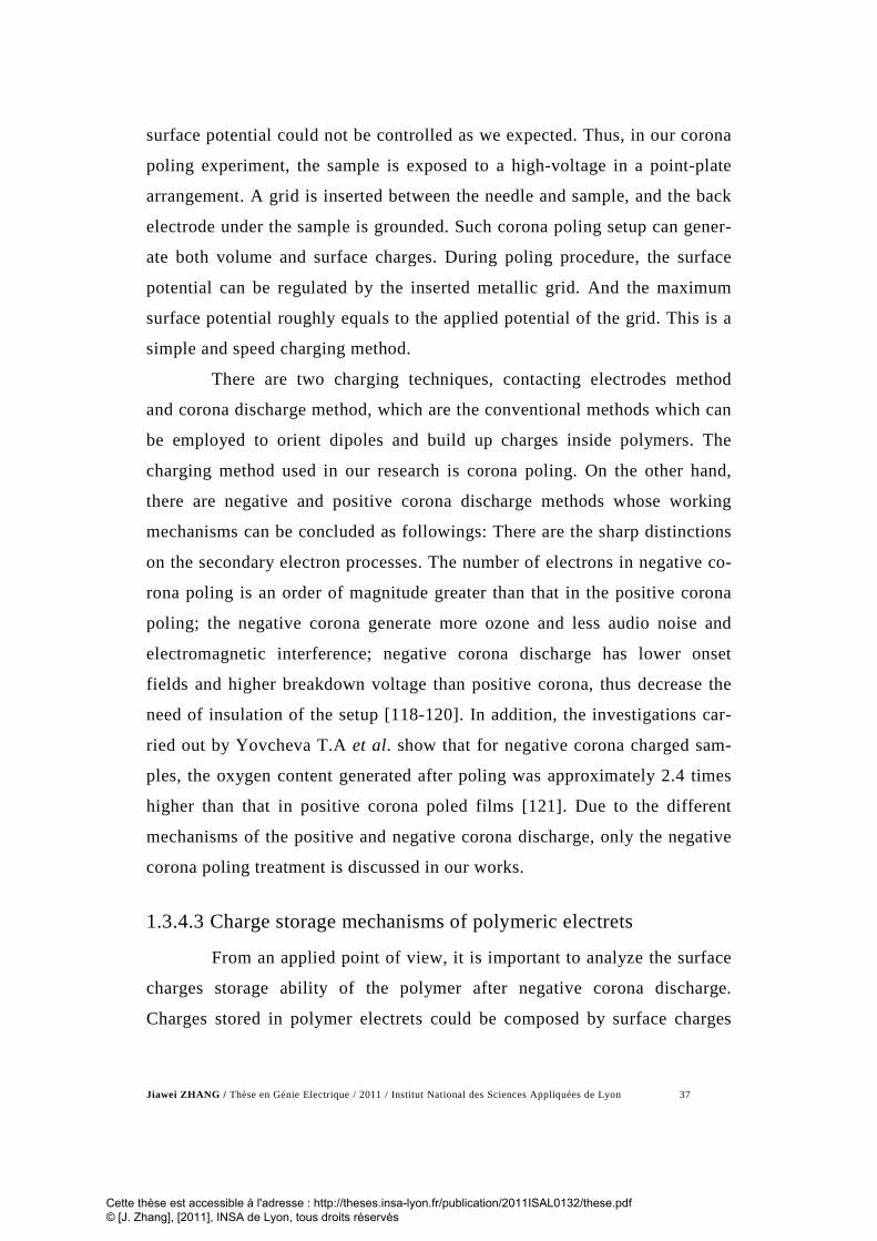
Jiawei ZHANG / Thèse en Génie Electrique / 2011 / Institut National des Sciences Appliquées de Lyon 37
surface potential could not be controlled as we expected. Thus, in our corona
poling experiment, the sample is exposed to a high-voltage in a point-plate
arrangement. A grid is inserted between the needle and sample, and the back
electrode under the sample is grounded. Such corona poling setup can gener-
ate both volume and surface charges. During poling procedure, the surface
potential can be regulated by the inserted metallic grid. And the maximum
surface potential roughly equals to the applied potential of the grid. This is a
simple and speed charging method.
There are two charging techniques, contacting electrodes method
and corona discharge method, which are the conventional methods which can
be employed to orient dipoles and build up charges inside polymers. The
charging method used in our research is corona poling. On the other hand,
there are negative and positive corona discharge methods whose working
mechanisms can be concluded as followings: There are the sharp distinctions
on the secondary electron processes. The number of electrons in negative co-
rona poling is an order of magnitude greater than that in the positive corona
poling; the negative corona generate more ozone and less audio noise and
electromagnetic interference; negative corona discharge has lower onset
fields and higher breakdown voltage than positive corona, thus decrease the
need of insulation of the setup [118-120]. In addition, the investigations car-
ried out by Yovcheva T.A et al. show that for negative corona charged sam-
ples, the oxygen content generated after poling was approximately 2.4 times
higher than that in positive corona poled films [121]. Due to the different
mechanisms of the positive and negative corona discharge, only the negative
corona poling treatment is discussed in our works.
1.3.4.3 Charge storage mechanisms of polymeric electrets
From an applied point of view, it is important to analyze the surface
charges storage ability of the polymer after negative corona discharge.
Charges stored in polymer electrets could be composed by surface charges
Cette thèse est accessible à l'adresse : http://theses.insa-lyon.fr/publication/2011ISAL0132/these.pdf © [J. Zhang], [2011], INSA de Lyon, tous droits réservés

Jiawei ZHANG / Thèse en Génie Electrique / 2011 / Institut National des Sciences Appliquées de Lyon 38
and injected charges which are captured by traps distributed on the surface
and in the electret’s volume. According to [122], the charge storage capabil-
ity of an electret polymer film is mainly determined by its chemical nature.
For semicrystalline polyolefines, the lamellarcrystals embedded in the amor-
phous matrix form a heterogeneous morphology, where charge trapping and
transport mechanisms depend on the crystallinity. The shallow traps are lo-
cated in the peripheral and surface layer of the electret film, whereas charges
in higher release energy traps are deposited in the central region of the
spherulites [123, 124]. There are a number of factors that have effect on the
charge storage ability and dipole orientation of polymeric electrets such as
chemical impurities, inside voids structure, surface roughness condition,
macro-molecular arrangements, particles added in the polymers, chemical
composition, discharge conditions (needle and grid voltage, charging time
and temperature etc.) and metal electrode spurred on the surface of the elec-
trets etc..
In Ref.[125], the researchers pointed out that the magnitude of the
surface voltage on the polymer films due to the corona discharge, associated
with charge retain ability, was a function of the strength of the applied volt-
age to the corona needle, the time relative to the voltage application, and the
temperature. According to [126], the results also show that charging poly-
mers at a relative high temperature dramatically increases their charge stabil-
ity. As the charging temperature is increased, one tends to fill deeper traps
because of changes in relative capture and escape probabilities. Besides, the
influence of high humidity and porosity on the surface-charge decay and sta-
bility was investigated in [127, 128]. The effect of the samples’ roughness on
the charge stability has been mentioned in [5], but experimental results were
not presented their piece of work. In order to explore the application poten-
tial of such polymers, this paper gives, for the first time, the numerical re-
sults under different charge conditions.
Cette thèse est accessible à l'adresse : http://theses.insa-lyon.fr/publication/2011ISAL0132/these.pdf © [J. Zhang], [2011], INSA de Lyon, tous droits réservés

Jiawei ZHANG / Thèse en Génie Electrique / 2011 / Institut National des Sciences Appliquées de Lyon 39
Therefore, the charging behaviour has been found to be associated
with some details such as: the sample preparation, surface roughness condi-
tion as well as residual stresses [129]. According to [130, 131], the charge
forced into the bulk is more permanent than surface charge since it is not re-
moved from the polymer by grounding, and they have also demonstrated that
there is a named “memory” effect with the poling current and to the accumu-
lation of trapped charge in the polymer matrix which are released only after
the polymer is heated to high above its temperature of glass transition (Tg).
Charge storage mechanism of negative corona-charged PP has been
widely studied [14-17]. By using the Thermal Stimulated Depolarization Cur-
rent (TSDC) method, de-trapped charges and a relaxation of the polarization
have been observed by Ono et al. [5]. Furthermore, the Laser Induced Pres-
sure Pulse (LIPP) technique has also been used in former investigations for
displaying the charge distribution in their research. By integration of the
TSDC current, the quantity of charges induced by the high corona voltage
treatment can be calculated on such commercial cellular PP.
1.4 Conclusion
The literatures review, development history and application in many
fields have been reported on the magnetoelectric and electrostrictive effects.
Firstly, magnetoelectric materials are an important class of multifer-
roic materials which have received considerable attention in the past decade.
The composite laminates which process large ME coefficient, have tremen-
dous application potential on the field of ME sensors, transducers, switches
and phase inverters etc..
Secondly, as an electroactive polymer, the cellular polypropylene
electret can store a number of charges after corona poling. Efforts on investi-
gating its charge storage mechanism have been made by many scholars.
Cette thèse est accessible à l'adresse : http://theses.insa-lyon.fr/publication/2011ISAL0132/these.pdf © [J. Zhang], [2011], INSA de Lyon, tous droits réservés

Jiawei ZHANG / Thèse en Génie Electrique / 2011 / Institut National des Sciences Appliquées de Lyon 40
However, few studies have been done to investigate how the electrostrictive
performance of charged cellular PP electret can be influenced by the corona
discharge treatment.
Cette thèse est accessible à l'adresse : http://theses.insa-lyon.fr/publication/2011ISAL0132/these.pdf © [J. Zhang], [2011], INSA de Lyon, tous droits réservés

Jiawei ZHANG / Thèse en Génie Electrique / 2011 / Institut National des Sciences Appliquées de Lyon 41
Chapter 2. Sample preparation of laminate composites and their magnetoelectric experiments
2.1 Introduction
We report on the magnetoelectric experiment on the bi- and tri-
layered composites consisting of polyvinylidene fluoride (PVDF) and poly-
urethane (PU) filled with magnetically hard magnetite Fe3O4 or Terfernol-D
(Te-D) magnetostrictive material. PU composite film fabrication procedure
has been described in this section, and the magnetoelectric experiments based
on PU composite have been presented. Then, a new approach that can
achieve the ME coupling using only electroded piezoelectric compounds sub-
jected to ac magnetic flux has been attempted. The magnetoelectric experi-
ment set-up and condition such as magnitude and direction of applied mag-
netic field on piezoelectric unimorph bender, PVDF film and piezoelectric
ceramic disc have been introduced in this chapter. Based on this early proto-
type, we developed a magnetoelectric sensor which can realize ac/dc mag-
netic field sensing without applying ac current source on the sample directly.
Cette thèse est accessible à l'adresse : http://theses.insa-lyon.fr/publication/2011ISAL0132/these.pdf © [J. Zhang], [2011], INSA de Lyon, tous droits réservés

Jiawei ZHANG / Thèse en Génie Electrique / 2011 / Institut National des Sciences Appliquées de Lyon 42
2.2 Multi-layer polymer composites
The origin of the ME effect is often associated with an interaction
mechanism between various compounds of ME matter. In the present case,
magnetostrictive and piezoelectric phases were combined to obtain a dra-
matic enhancement of the ME effects, relative to single phase materials. High
magnetoelastic interactions are found for very few magnetostrictive materials.
Accordingly, two kinds of magnetostrictive fillers were selected:
Tb0.3Dy0.7Fe1.9−1.95, commercially known as Terfenol-D (with a highest
magnetostriction at room-temperature) at an optimum concentration in PU of
50 wt%, which yields a large ME response, and the 2 wt% Fe3O4 powder
used as filler in PU for the same reason [132]. In magnetostrictive materials,
the strain induced by the applied magnetic field is proportional to the square
of the magnetic field. An effective linear operational range can be achieved
by applying a (dc) magnetic bias across the structure.
The samples tested in this part were tri- and bi-layered polymer
composites consisting of polyvinylidene fluoride (PVDF) and polyurethane
(PU) filled with amorphous magnetic Fe3O4 micropowder (Aldrich, average
particle size: 200 μm) or Terfenol-D (TeD) particles of <300 μm in size
(Etrema Products, Inc., Ames, IA). For a of magnetic field frequency 1 kHz,
the micro-sized magnetic powder used to make the PU composites gives a
better response than nano-sized magnetic powder. The compositions of the
samples were the following: (PU+2 wt% Fe3O4 /PVDF/ PU+2 wt% Fe3O4),
(PU+2 wt% Fe3O4 /PVDF), (PU+50 wt% TeD /PVDF/ PU+50 wt% TeD) and
(PU+50 wt% TeD /PVDF).
Cette thèse est accessible à l'adresse : http://theses.insa-lyon.fr/publication/2011ISAL0132/these.pdf © [J. Zhang], [2011], INSA de Lyon, tous droits réservés

Jiawei ZHANG / Thèse en Génie Electrique / 2011 / Institut National des Sciences Appliquées de Lyon 43
2.2.1 Film fabrication procedure
Fabrication procedure is as shown in Fig. 2. 1, the selected polyure-
thane (PU) was the polyether-type thermoplastic TPU5888 from Noveon
Company.
Fig. 2. 1 The fabrication procedure of composite solution
PU
DMF
Polyurethane granules+ N,N dimethylformamide
(DMF)
80 oC
Mixed for 45 min at 80 oC
80 oC
Composite so-lution
The fillers are dispersed by ultrasonics processor for 20 min.
DMF
Micro/Nano fillers
Ultrasonic
Stirred 60 min at 80oC
80 oC
80 oC
Composite film
Cette thèse est accessible à l'adresse : http://theses.insa-lyon.fr/publication/2011ISAL0132/these.pdf © [J. Zhang], [2011], INSA de Lyon, tous droits réservés

Jiawei ZHANG / Thèse en Génie Electrique / 2011 / Institut National des Sciences Appliquées de Lyon 44
Fig. 2. 2 The fabrication procedure from composite solution to PU composite films
The polymer films were prepared through solution casting. PU gran-
ules were first pre-dissolved in N,N-dimethylformamide (DMF) at ∼ 80°C for
one hour. Then, the fabrication procedure of composite films is shown in Fig.
2. 2. During the fabrication procedure, x wt.% of the magnetic particles
(Fe3O4 or TeD) were added to the mechanically stirred solution. Stirring was
performed at a constant temperature, for between 1.5 hours and 2.5 hours.
The mixed solution was subsequently spin coated onto a glass plate, degassed
to eliminate voids and dried at 70°C for 6 hours. After this, composite films
130 oC for 3 hr
Precursor solution Coating solution on glass
Film deposit with Spin coater
Drying and removing from the glass
Annealing
Cette thèse est accessible à l'adresse : http://theses.insa-lyon.fr/publication/2011ISAL0132/these.pdf © [J. Zhang], [2011], INSA de Lyon, tous droits réservés

Jiawei ZHANG / Thèse en Génie Electrique / 2011 / Institut National des Sciences Appliquées de Lyon 45
were cut into rectangular pieces (∼200 microns thick, 40 mm long and 10 mm
wide).
2.2.2 Tri- and bi-layered polymer composites fabrication
The PVDF films supplied by PIEZOTECH S.A. Saint-Louis, France,
were 25 µm thick, 10 mm wide, 45 mm long and uni-axially stretched along
the length direction. Cr/Al Electrodes were sputtered on both surfaces and
film polarization direction was perpendicularly to the sample’s plane. Finally,
the piezoelectric (PVDF sample) and magnetostrictive layers were glued to-
gether using an epoxy resin. The multilayer sample was then pressed tightly
during several hours, to minimize the effect the glue layer thickness.
2.3 Experiments on piezoelectric unimorph bender and PVDF film
2.3.1 Early ME experiments on piezoelectric unimorph bender and PVDF
The previous studies based on coupling between Lorentz forces and
piezoelectricity, are presented in [64-66, 83] and summarized in §1.2.5. The
common characteristic of designed ME experiments is the direct ac current
appliance on the samples to generate Lorentz Forces. In the present study, an
attempt was made to obtain ME coupling in PZT/metal layered composites
by designing specific ME set-up which avoids applied ac current directly on
the samples. The aluminium plat bonded with silver electroded PZT ceramic,
can be made into a unimorph.
Cette thèse est accessible à l'adresse : http://theses.insa-lyon.fr/publication/2011ISAL0132/these.pdf © [J. Zhang], [2011], INSA de Lyon, tous droits réservés

Jiawei ZHANG / Thèse en Génie Electrique / 2011 / Institut National des Sciences Appliquées de Lyon 46
The PZT ceramic used in our experiment was a soft-type PZT-P188
(Saint-Gobain Quartz Company) plate of 450 microns thick, 30mm length
and 10 mm width. Before poling in the thickness direction, it was electroded
on both sides with silver paste (supplied by Degussa) fired at 600°C. Then,
after poling, the PZT and an alumina layer of 200 microns thick were epoxied
together to create a unimorph bender. The cantilever piezoelectric bender was
then clamped at one side and horizontally suspended. In order to predict the
ME coefficients in the region around the sample’s resonance frequency (4.9
kHz), it was simultaneously subjected to an ac magnetic field hac (magnitude:
Hac = 1 Oe) provided by a Helmholtz coil and a dc bias field (Hdc up to 2.2
kOe) generated by permanent magnets [21, 132]. Similarly, the PVDF soft
film were 25 µm thick, 10 mm wide, 45 mm long, clamped in the test bench
and subjected the same conditions of magnetic field.
In order to observe the influence of magnitude and direction of ap-
plied magnetic field, we work out four possible experimental configurations
associated with different condition of hac and Hdc. Then, the magnetoelectric
response was obtained by measuring the magnetic-field-induced piezoelectric
current iME at room temperature with a current amplifier (Keithley 428, USA)
combined with a lock-in amplifier (SR 830 Stanford Research Systems) tuned
to the ac field frequency f.
2.3.2 Magnetoelectric sensor based on piezoelectric unimorph bender
Based on the former research of magnetoelectric effect of the piezo-
electric unimorph bender, we developed a prototype of a ME sensor by using
an electric conducting wire with ac current to replace the ac magnetic coils
used in the initial setup and the cantilevered piezoelectric unimorph bender.
Fig. 2. 3 illustrates the diagram of the designed ac/dc ME sensor in the Carte-
sian coordinate system. The ac rotating magnetic fields around ac conducting
Cette thèse est accessible à l'adresse : http://theses.insa-lyon.fr/publication/2011ISAL0132/these.pdf © [J. Zhang], [2011], INSA de Lyon, tous droits réservés

Jiawei ZHANG / Thèse en Génie Electrique / 2011 / Institut National des Sciences Appliquées de Lyon 47
wire generated magnetic flux in the silver electrodes crossing the thickness
direction of unimorph bender, which was the cause of eddy current within the
silver electrode. Consequently, there were Lorentz forces in such single
phase piezoelectric bender which induced apparent magnetoelectric response
without adding any magnetic phase in such new developed sensor.
Fig. 2. 3 Schematic diagram of the rectangular shape piezoelectric unimorph bender
subjected to ac and dc magnetic fields.
For the magnetoelectric measurement, the photograph of the experi-
mental test bench is shown in Fig. 2. 4. Applied ac current was through a
conducting wire which was one part of a closed circuit composed by wave-
form generator (Agilent 33220A), voltage amplifier (4505 NF Electronics)
and a resistance. The wire was put vertically close to PZT unimorph bender
with the distance of 4mm, to generate the ac rotating magnetic field hac, at its
bending-mode resonance frequency. Thus, the magnitude of ac magnetic in-
duction Bac is µ0Hac with µ0 the permeability of free space. The unimorph
bender and the conducting wire were inserted between the poles of the elec-
tromagnet horizontally and vertically, respectively (Fig. 2. 3 and Fig. 2. 5).
This allowed the dc magnetic field Hdc appliance along the sample’s length
(direction “2”). Experimentally, the magnitude of the dc magnetic field on
Cette thèse est accessible à l'adresse : http://theses.insa-lyon.fr/publication/2011ISAL0132/these.pdf © [J. Zhang], [2011], INSA de Lyon, tous droits réservés

Jiawei ZHANG / Thèse en Génie Electrique / 2011 / Institut National des Sciences Appliquées de Lyon 48
the proposed ME sensor was measured in the air-gap between the poles of the
electromagnet, using a tesla-meter (F.W. Bell 5080) [133-135].
Laser Controller
Lock-in Amplifier
Laser Sensor Head PZT Unimorph
Bender
Lock-in Amplifier
Poles of Electromagnet
Tesla Meter
Fig. 2. 4 Photograph of the ME experimental test bench
Fig. 2. 5 Schematic drawing of the experimental system of ME sensor and its vibration
velocity measurement
Cette thèse est accessible à l'adresse : http://theses.insa-lyon.fr/publication/2011ISAL0132/these.pdf © [J. Zhang], [2011], INSA de Lyon, tous droits réservés

Jiawei ZHANG / Thèse en Génie Electrique / 2011 / Institut National des Sciences Appliquées de Lyon 49
As shown in Fig. 2. 5 and Fig. 2. 6, The ac current-induced magnetic
field hac could be estimated close to the sample’s plane, which roughly corre-
sponds to an ac field applied in the direction “2”. The induced magnetoelec-
tric response was obtained by measuring the magnetic field-induced piezo-
electric voltage at room temperature with a lock-in amplifier connected with
unimorph bender and tuned to the ac field frequency f. The PZT electrodes
were connected to the lock-in-amplifier with two thin wires soldered close to
its clamped edge. Meanwhile, in order to demonstrate that the studied ME ef-
fect was a coupled magnetic and electrical response via mechanical interac-
tion between alumina plate and piezoelectric beam, a velocity measurement
was also performed on the edge of the PZT unimorph bender using a laser vi-
brometer system which was composed by a sensor head (OFV-505 Polytec.
France) and a laser controller (OFV-5000 Polytec. France).
Fig. 2. 6 Detailed schematic drawing PZT unimorph sensor between two magnetic
poles
2.3.3 ME experiments on PVDF film
Then, with the aim to observe the same effect as PZT unimorph
bender, we have designed a similar ME experiment set-up for the single pie-
zoelectric polymer PVDF supplied by PIEZOTECH S.A. Saint-Louis, France,
with the 25μm thick, 10mm wide and 40mm long. As shown in Fig. 2. 7, the
Cette thèse est accessible à l'adresse : http://theses.insa-lyon.fr/publication/2011ISAL0132/these.pdf © [J. Zhang], [2011], INSA de Lyon, tous droits réservés

Jiawei ZHANG / Thèse en Génie Electrique / 2011 / Institut National des Sciences Appliquées de Lyon 50
electroded PVDF film was vertically suspended by clamping the upper end.
The ME current was obtained by a current amplifier. The magnet field was
provided by the same equipments as PZT unimorph bender with the magni-
tude: Hdc: -2k Oe~2k Oe, Hac=1Oe, fr=60Hz; and their directions shown as
in figure. Horizontal deflection (δ) of the free end of the film was measured
by the laser vibrometer system.
Fig. 2. 7 Schematic diagram of the rectangular shape PVDF film subjected to ac and
dc magnetic fields
Vibrometer
Gold electroded PVDF film
δ
3
1
2
Hdc
Current amplifier
Hac
Cette thèse est accessible à l'adresse : http://theses.insa-lyon.fr/publication/2011ISAL0132/these.pdf © [J. Zhang], [2011], INSA de Lyon, tous droits réservés

Jiawei ZHANG / Thèse en Génie Electrique / 2011 / Institut National des Sciences Appliquées de Lyon 51
2.4 Magnetoelectric sensor based on a single piezoelectric ceramic disc
Based on former ME measurement, we can observe the apparent
magnetoelectric performance of the unimorph bender and vibration caused by
Lorenz force acting on the sample. In order to establish the mathematic mod-
elling and work out the relation between the ME output voltage and Lorenz
force induced by eddy current. The studied piezoelectric ceramic sample was
changed as a PZT ceramic disc which was elaborated in our Laboratory. The
ceramic disc was 500 microns thick with a radius R = 27.5 mm. This high as-
pect ratio has been deliberately chosen in order to amplify the radial vibra-
tion mode since the ceramic has been electrically poled in the thickness di-
rection after silver electrodes deposition on both sides (silver paste supplied
by Degussa fired at 600°C).
For magnetoelectric measurement, a dynamic magnetoelectric set up
in which both dc and ac magnetic fields can be varied is composed of an
electromagnet providing the dc magnetic field appliance (Hdc) and two Hel-
molhtz coils inserted on the poles of the electromagnet to generate the ac
magnetic field hac, (as former hac=Hacejωt with j2=-1, ω is the angular fre-
quency and the magnitude: Hac = 0.1 Oe i.e. the magnitude of ac magnetic
induction is Bac =μ0Hac=10-5 T). Thus, in this configuration, both ac and dc
fields are parallel each other. The PZT ceramic was inserted vertically be-
tween the poles of the electromagnet and its plane was perpendicular to the
ac and dc magnetic fields, as shown in Fig. 2. 8. The magnetoelectric re-
sponse was obtained by measuring the magnetic field-induced piezoelectric
current at room temperature with a current amplifier (Stanford) combined
with a lock-in amplifier tuned to the ac field frequency f=ω/2π. In the follow-
ing, fr = 36 kHz which is the electromechanical resonance (EMR) frequency
of the tested disc in the radial mode). The two silver electrodes are connected
Cette thèse est accessible à l'adresse : http://theses.insa-lyon.fr/publication/2011ISAL0132/these.pdf © [J. Zhang], [2011], INSA de Lyon, tous droits réservés

Jiawei ZHANG / Thèse en Génie Electrique / 2011 / Institut National des Sciences Appliquées de Lyon 52
to the current amplifier with two thin wires soldered close to the edge of the
disc, which is suspended in the airgap of the electromagnet. At the same time,
in order to demonstrate that the studied ME effect is a coupled magnetic and
electrical phenomenon via mechanical interaction, the radial velocity meas-
urements were also performed on the edge of the ceramic using a laser vi-
brometer (Polytec. France).
Hac
Hdc
Piezo ceramic disc current
amplifier
Helmoltz coils poles
Fig. 2. 8 Schematic diagram of the piezo-ceramic disc in ME measuring system
2.5 Conclusion
In this chapter, we have introduced the magnetoelectric experiments
on the composites laminates including PVDF layer and PU laminate filled
with magnetically hard magnetite fillers such as Fe3O4 or Te-D. Film fabrica-
tion procedure including composite solution preparation, film deposition, stir,
anneal and conditions of ME experiments including direction and magnitude
of applied magnetic field, ac magnetic field frequency have been stated in de-
tail. In addition, we have presented another ME experimental set-up based on
Lorentz force induced ME effect made on PZT unimorph bender, piezoelec-
Cette thèse est accessible à l'adresse : http://theses.insa-lyon.fr/publication/2011ISAL0132/these.pdf © [J. Zhang], [2011], INSA de Lyon, tous droits réservés

Jiawei ZHANG / Thèse en Génie Electrique / 2011 / Institut National des Sciences Appliquées de Lyon 53
tric PVDF film and PZT ceramic disc. Different conditions of ME experi-
ments such as magnitude and direction of applied magnetic field have been
designed out. We try to develop a ME sensor without ac current applied di-
rectly on the sample, which is different with previous ME experiments based
on Lorentz force and can be used as ac and dc magnetic field sensors and ac-
tuators under certain condition.
Cette thèse est accessible à l'adresse : http://theses.insa-lyon.fr/publication/2011ISAL0132/these.pdf © [J. Zhang], [2011], INSA de Lyon, tous droits réservés

Jiawei ZHANG / Thèse en Génie Electrique / 2011 / Institut National des Sciences Appliquées de Lyon 54
Chapter 3. Experiments for analysing the charge storage mechanisms and the electrostriction of corona charged cellular PP
3.1 Introduction
In this chapter, we present charged cellular polypropylene with co-
rona poling set-up. A series of experiment including Surface Potential Decay
measurement (SPD), Thermal Stimulated Depolarization Current experiment
(TSDC), and Differential Scanning Calorimetry experiment (DSC) has been
described schematically and literally. Finally, the experiment of electrostric-
tive performance testing has been introduced, in order to examine electro-
striction of the charged films under applied electric filed.
3.2 Experimental setup of corona discharge method
The chosen samples, denoted PQ50 whose thickness and density are
50µm and 600kg/m3 respectively, were supplied by Sodinor Company
Cette thèse est accessible à l'adresse : http://theses.insa-lyon.fr/publication/2011ISAL0132/these.pdf © [J. Zhang], [2011], INSA de Lyon, tous droits réservés

Jiawei ZHANG / Thèse en Génie Electrique / 2011 / Institut National des Sciences Appliquées de Lyon 55
(France). Cellular polypropylene films (4×4cm2) were charged using a corona
triode, which is schematically presented in Fig. 3. 1.
Fig. 3. 1 The corona discharge setup.
The charged films were coated with a gold electrode on one surface
(20 nm thick) under high vacuum by a High Resolution Sputter Coater. Then,
with a corona triode, the electrical charges were injected for a duration of 10
min through the non-metalized surface of the samples which were placed un-
der a stainless grid (size of mesh screen is 150µm) in order to maintain a uni-
form surface potential. With the aim of investigating the charge storage per-
formance and its influence on the electrostrictive performance of fully
charged cellular PP, the corona voltages were kept at -30 kV and a grid volt-
age of -4kV was employed.
Cette thèse est accessible à l'adresse : http://theses.insa-lyon.fr/publication/2011ISAL0132/these.pdf © [J. Zhang], [2011], INSA de Lyon, tous droits réservés

Jiawei ZHANG / Thèse en Génie Electrique / 2011 / Institut National des Sciences Appliquées de Lyon 56
3.3 Surface potential measurement
Surface potential decay (SPD) measurement have been extensively
employed for investigation of electrical characterization of electrets surfaces
after corona charging, due to their advantages such as simple and easy to im-
plement, reliability and low cost [136-139]. It is one of the criteria to esti-
mate charge-retaining ability of the polymer.
(a)
(b)
Fig. 3. 2 (a) photograph of the surface potential test setup (b) Schematic representation
of the surface potential measurement setup [140]
Oscilloscope
Electrostatic Voltmeter
Probe
Sample
Cette thèse est accessible à l'adresse : http://theses.insa-lyon.fr/publication/2011ISAL0132/these.pdf © [J. Zhang], [2011], INSA de Lyon, tous droits réservés

Jiawei ZHANG / Thèse en Génie Electrique / 2011 / Institut National des Sciences Appliquées de Lyon 57
Immediately following the corona treatment, in order to observe its
charge-decay tendency, the surface potentials of non-charged, and charged
cellular PP were measured by an Electrostatic Voltmeter (Model 541 TREK).
An electrostatic charge monitoring probe is placed close 1cm to the surface
to measure its surface potential through non-contact method. At the same
time, the surface potential decay of the charged samples could be recorded
with the help of an oscilloscope (DSO6034A Agilent). The surface potential
measuring setup used in this work is shown in Fig. 3. 2, in which the probe
acts as a vibrating capacitor, formed between the probe and the sample.
3.4 Relative permittivity measurement
The charged films were coated with a gold electrode on two surfaces
(20 nm thick) under high vacuum by a High Resolution Sputter Coater (208
HR, Cressington), and their relative permittivity at 0.1Hz was measured by
using a permittivity measurement system (1255A Frequency Response Ana-
lyzer combined with a 1296 Dielectric Interface, Solartron, United Kingdom).
3.5 Measurement of Young’s modulus
Young's modulus, Y, is an indicator of the stiffness of a film. It is
determined from the value for the resulting stress applied to the material di-
vided by the value for the applied strain in the same direction. An experiment
for measuring the Young’s modulus of the film with Ultra-Precision Linear
Motor Stage, 50 mm Travel (Newsport XMS 50 France), Motion Control-
ler/Driver (Newsport XPS France), oscilloscope and computer which are
shown in Fig. 3. 3. The measured value of Young’s modulus of cellular PP is
1GPa.
Cette thèse est accessible à l'adresse : http://theses.insa-lyon.fr/publication/2011ISAL0132/these.pdf © [J. Zhang], [2011], INSA de Lyon, tous droits réservés

Jiawei ZHANG / Thèse en Génie Electrique / 2011 / Institut National des Sciences Appliquées de Lyon 58
(a)
(b) Fig. 3. 3 (a) Photograph Test bench of Young’s modulus measurement; (b)Schematic
of measuring system of Young’s modulus
Polymer Force Sensor
Newport Motion
Controller+PC Oscilloscope
Newport Ultra-Precision Linear Motor Stage
Waveform Generator
Polymer Force Sensor
250N/12V
Newport Ultra-Precision Linear Motor Stage
Cette thèse est accessible à l'adresse : http://theses.insa-lyon.fr/publication/2011ISAL0132/these.pdf © [J. Zhang], [2011], INSA de Lyon, tous droits réservés

Jiawei ZHANG / Thèse en Génie Electrique / 2011 / Institut National des Sciences Appliquées de Lyon 59
3.6 TSDC measurement
Thermal Stimulated Depolarization Current (TSDC) measurements
were performed in order to investigate the exact quantity of charge stored on
the surface and within the cellular PP. The stimulated current’s spectrum ver-
sus the temperature can be used to obtain the important information of
charges storing and de-trapping situation, which can also be a reference to
understand the long-term storage mechanism in electrets. For these TSC ex-
periments, a charged sample was placed in a test chamber with temperature
control (Chamber VT7004, Vötsch Industrietechnik, Germany).
(a)
(b)
Fig. 3. 4 (a) The experimental process of the TSC technique; (b) Schematic of the
TSDC technique
As shown in Fig. 3. 4, the two -surfaces-electroded sample was
sandwiched between two copper plates, short-circuited and maintained at
Cette thèse est accessible à l'adresse : http://theses.insa-lyon.fr/publication/2011ISAL0132/these.pdf © [J. Zhang], [2011], INSA de Lyon, tous droits réservés

Jiawei ZHANG / Thèse en Génie Electrique / 2011 / Institut National des Sciences Appliquées de Lyon 60
23°C for one hour in order to release the surface charge, after which the tem-
perature was linearly increased from 23°C to 140°C at a rate of 5°C/min. The
TSDC current signal was measured with the help of a current amplifier. In
the meantime, the over-all thermal-current spectrum of the tested sample was
registered by a data acquisition recorder (BD300 Series Kipp & Zonen
Vötsch Industrietechnik, Germany).
The total charge Qcorona within the cellular PP was calculated by in-
tegrating the TSC current, itsc, according to:
0
t
corona tscQ i dt= ∫ (3.1)
3.7 Differential scanning calorimetry measurement
3.7.1 Principle of data acquisition in the differential scanning calorimetry
Differential scanning calorimetry (DSC) is a useful tool for measur-
ing heat capacity variations induced by phase transitions: i.e. melting, the
glass transition or crystallization. It is a technique for measuring the energy
necessary to establish a nearly zero temperature difference between a sub-
stance and an inert reference material, as the two specimens are subjected to
identical temperature regimes in an environment heated or cooled at a con-
trolled rate [141].
As shown in Fig. 3. 5, during the DSC experiment, the change of
heat capacity is detected. Then, the equilibrium between sample and refer-
ence is disturbed. When the sample temperature is higher (exothermic event)
Cette thèse est accessible à l'adresse : http://theses.insa-lyon.fr/publication/2011ISAL0132/these.pdf © [J. Zhang], [2011], INSA de Lyon, tous droits réservés

Jiawei ZHANG / Thèse en Génie Electrique / 2011 / Institut National des Sciences Appliquées de Lyon 61
or lower (endothermic event) than the reference, this temperature difference
is detected by a temperature controlling system and the differential heat flow
between sample and reference can be calculated [142, 143]. In our studies we
use the DSC to deduce the crystallinity of the film, for instance [144].
Fig. 3. 5 Scheme of DSC instrument [143]
3.7.2 Procedure of DSC test
The samples were placed in a closed aluminium crucible in the DSC
equipment (DSC 131 evo Setaram France), where they were heated from
23°C to 200°C and cooled down to 23°C at a controlled rate of 10°C/min.
The heat flow was recorded synchronously by a computer connected to the
DSC equipment. In heat flux DSC, the sample and reference are connected by
a low resistance heat flow path (a metal disc) symmetrically. The assembly is
enclosed in a single furnace. Enthalpy or heat capacity changes in the sample
cause a difference in its temperature relative to the reference [143].
Cette thèse est accessible à l'adresse : http://theses.insa-lyon.fr/publication/2011ISAL0132/these.pdf © [J. Zhang], [2011], INSA de Lyon, tous droits réservés

Jiawei ZHANG / Thèse en Génie Electrique / 2011 / Institut National des Sciences Appliquées de Lyon 62
3.7.3 Electrostrictive coefficient measurement
As shown in Fig. 3. 6, strain versus electric field was measured with
the help of a non-contact capacitive measurement sensor (FOGALE MC 940)
on disc-shaped samples with a precision on the order of 10 nm. Because PP
were elastically much softer than ceramics and the samples were made into
very thin films, great care must be taken in the strain measurements of PP to
ensure the accuracy of the data when applied a electric field on it. For such
soft film like materials flexure motion and mechanical clamping of a sample
are two major causes of errors in the strain measurements.
Fig. 3. 6 The electrostrictive coefficient measurement setup
Cette thèse est accessible à l'adresse : http://theses.insa-lyon.fr/publication/2011ISAL0132/these.pdf © [J. Zhang], [2011], INSA de Lyon, tous droits réservés

Jiawei ZHANG / Thèse en Génie Electrique / 2011 / Institut National des Sciences Appliquées de Lyon 63
The film samples were placed on horizontal stainless steel discs (20
mm in diameter) in order to avoid measuring a parasitic flexure motion, and a
second brass disc positioned on the top of the film rendered it possible to ap-
ply a bipolar electric field. The total weight of piece 2, 3 and 4 was 5g
(equivalent to 156Pa) which was a suitable small stress, in order to avoid
clamping of the sample. The sample was subjected to electric field with the
help of a waveform generator for which the output was amplified through a
high-voltage amplifier (TREK 609D-6). The frequency and the magnitude of
the applied ac electric field were 0.1 Hz and 12.5 V/µm, respectively. During
these strain versus electric field measurements, the electric polarization was
calculated by integration of the measured current through the sample by
means of a current amplifier.
3.8 Conclusion
Since the parameters in corona discharge set-up could influence the
result of charge injection, the mesh size of inserted metal grid, applied high-
voltage amplitude on the discharge electrode, sample dimension and distance
between charged sample and electrode in corona discharge configurations,
have been introduced. Then, after corona poling, in order to investigate the
surface charge retaining ability, distribution situation and depolarization
principle of retained charge, as well as thermal trace characterization after
corona discharge treatment in cellular PP, the experiments such as Surface
Potential Decay Test, Thermal Stimulated Depolarization Current (TSDC)
experiment, and Differential Scanning Calorimetry (DSC) experiment have
been designed. Then, with the aim to find the influence of stored charges on
the electrostrictive performance of charged films, a set-up that can measure
their deformation under an external applied electric field has been introduced.
Cette thèse est accessible à l'adresse : http://theses.insa-lyon.fr/publication/2011ISAL0132/these.pdf © [J. Zhang], [2011], INSA de Lyon, tous droits réservés

Jiawei ZHANG / Thèse en Génie Electrique / 2011 / Institut National des Sciences Appliquées de Lyon 64
It contained a non-contact capacitive sensor, current and voltage amplifier,
oscilloscope, clamped electrode and supporting rod.
Cette thèse est accessible à l'adresse : http://theses.insa-lyon.fr/publication/2011ISAL0132/these.pdf © [J. Zhang], [2011], INSA de Lyon, tous droits réservés

Jiawei ZHANG / Thèse en Génie Electrique / 2011 / Institut National des Sciences Appliquées de Lyon 65
Chapter 4. Magnetoelectric results of laminate composites
4.1 Introduction
In recent years, it has been found that laminated composites made of
magnetostrictive and piezoelectric materials possess superior ME perfor-
mance owing to their giant product property effect between the
magnetostrictive and piezoelectric effects. But very few studies have been
devoted to the ME effect in laminate composites including magnetostrictive
polymeric layer. For this reason, in this chapter, we have studied the ME ef-
fect based on magneto-elastic-electric effect in bi- and tri-layered composites
consisting of thermoplastic polyurethane (PU) filled with magnetically hard
magnetite Fe3O4 or Terfenol-D (TeD) magnetostrictive alloy. Moreover, a
model, based on a driven damped oscillation system, has been developed to
evaluate the influence of the first and second-order ME coefficients on the dc
magnetic field-induced phase switching phenomenon between dynamic ME
current and the applied ac magnetic field.
On the other hand, normal magnetic sensor based on Lorentz force
effect can show an excellent linear response to magnetic field [64]. Based on
the previous researches on the magnetoelectric effect from the direct cou-
pling of the Lorentz force and piezoelectric effect, we have designed a series
of ME experiment using PZT unimorph bender, PVDF film and PZT ceramic
Cette thèse est accessible à l'adresse : http://theses.insa-lyon.fr/publication/2011ISAL0132/these.pdf © [J. Zhang], [2011], INSA de Lyon, tous droits réservés

Jiawei ZHANG / Thèse en Génie Electrique / 2011 / Institut National des Sciences Appliquées de Lyon 66
disc and expected to obtain an excellent ME output by combining the Lorentz
force effect with the piezoelectric effect without applying ac current directly
on the samples as the previous ME experiments. Finally, the modelling of
Lorentz forces induced ME effect in piezoelectric materials has been estab-
lished.
4.2 Magnetoelectric effect of laminate polymer composites
4.2.1 ME coupling in PU composite/PVDF laminates
The polyurethane matrix filled with magnetically hard magnetite
Fe3O4 or TeD is chosen in this experiment since it exhibits important magne-
tostrictive effect. While, the PVDF film is the soft polymer with piezoelectric
effect. Thus, the ME coupling between different layers should be produced
through the interaction between magnetostriction and piezoelectricity phe-
nomena. The present study focuses to the experimental observation and the
modelling of the ME effect at room temperature, in the bi- and tri-layered
polymers. The experimental results and calculation details are presented in
the following.
4.2.2 Experimental results and calculation details
The variation of the square of the output RMS value of the ME cur-
rent generated by multilayered samples (PU+2 wt% Fe3O4 /PVDF, PU+50
wt% TeD /PVDF and PU+50 wt% TeD /PVDF/ PU+50 wt% TeD) depend-
ence of the dc magnetic field is shown in Fig. 4. 1. The result shows that
Cette thèse est accessible à l'adresse : http://theses.insa-lyon.fr/publication/2011ISAL0132/these.pdf © [J. Zhang], [2011], INSA de Lyon, tous droits réservés
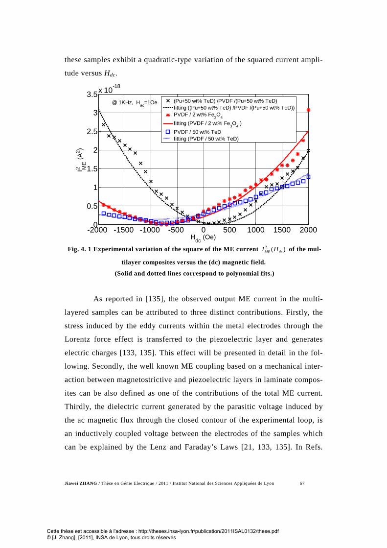
Jiawei ZHANG / Thèse en Génie Electrique / 2011 / Institut National des Sciences Appliquées de Lyon 67
these samples exhibit a quadratic-type variation of the squared current ampli-
tude versus Hdc.
-2000 -1500 -1000 -500 0 500 1000 1500 20000
0.5
1
1.5
2
2.5
3
3.5x 10⁻¹⁸I M
E2
(A2 )
Hdc (Oe)
(Pu+50 wt% TeD) /PVDF /(Pu+50 wt% TeD)fitting ((Pu+50 wt% TeD) /PVDF /(Pu+50 wt% TeD))PVDF / 2 wt% Fe3O4fitting (PVDF / 2 wt% Fe3O4 )PVDF / 50 wt% TeDfitting (PVDF / 50 wt% TeD)
@ 1KHz, Hac=1Oe
Fig. 4. 1 Experimental variation of the square of the ME current 2 ( )ME dcI H of the mul-
tilayer composites versus the (dc) magnetic field.
(Solid and dotted lines correspond to polynomial fits.)
As reported in [135], the observed output ME current in the multi-
layered samples can be attributed to three distinct contributions. Firstly, the
stress induced by the eddy currents within the metal electrodes through the
Lorentz force effect is transferred to the piezoelectric layer and generates
electric charges [133, 135]. This effect will be presented in detail in the fol-
lowing. Secondly, the well known ME coupling based on a mechanical inter-
action between magnetostrictive and piezoelectric layers in laminate compos-
ites can be also defined as one of the contributions of the total ME current.
Thirdly, the dielectric current generated by the parasitic voltage induced by
the ac magnetic flux through the closed contour of the experimental loop, is
an inductively coupled voltage between the electrodes of the samples which
can be explained by the Lenz and Faraday’s Laws [21, 133, 135]. In Refs.
Cette thèse est accessible à l'adresse : http://theses.insa-lyon.fr/publication/2011ISAL0132/these.pdf © [J. Zhang], [2011], INSA de Lyon, tous droits réservés

Jiawei ZHANG / Thèse en Génie Electrique / 2011 / Institut National des Sciences Appliquées de Lyon 68
[129, 131], the authors demonstrated that eddy current inducing magnetoelec-
tric effect is predominant only at the electromechanical resonance frequency
of the material. In this section, since the working frequency is 1 kHz, which
is far away from the electromechanical resonance frequency of the studied
ME composites, the influence of the eddy currents on the ME response can
be neglected. Thus, the total output ME current includes the magnetostric-
tively induced current and the dielectric current which is directly propor-
tional to the ac magnetic field and independent on the bias magnetic field.
Finally, the electric displacement of the samples may be written as
2.
1 .2
= +p pD H Hβ α (4.1)
where Pα is the linear polarization ME coefficient due to the “Lenz”
voltage and pβ is the bilinear polarization ME coefficient due to the
magnetostriction. Then, the corresponding output ME current is given by:
( ). . . .ME p dc ac p acDi A j A H h ht
β α ω∂ = = + + ∂ (4.2)
where A is the total surface area of the electrodes. In Eq.(4.2), since
only the experimental current at the frequency of the applied ac field is
measured by the lock-in amplifier, the second-order term at the frequency f
can be suppressed.
Consequently, the magnetoelectric current can be expressed as
. . . .ME Ptotal aci j A hα ω= (4.3)
where totalPα is the total ME coefficient:
Cette thèse est accessible à l'adresse : http://theses.insa-lyon.fr/publication/2011ISAL0132/these.pdf © [J. Zhang], [2011], INSA de Lyon, tous droits réservés

Jiawei ZHANG / Thèse en Génie Electrique / 2011 / Institut National des Sciences Appliquées de Lyon 69
( )Ptotal p p dc acH hα α β= + + (4.4)
The total magnetoelectric coupling coefficient takes the form:
total .ME
Pac
ijA h
αω
= − (4.5)
So, the modulus of totalPα is:
total0.
MEP
IA H
αω
= (4.6)
-2000 -1500 -1000 -500 0 500 1000 1500 200010-11
10-10
10-9
10-8
αp to
tal (C
/m2 .O
e)
Hdc (Oe)
PVDF / 50 wt% TeD(Pu+50 wt% TeD) /PVDF /(Pu+50wt% TeD)PVDF / 2 wt% Fe3O4 (Pu+2 wt% Fe3O4) /PVDF /(Pu+2wt% Fe3O4)
@1KHz, Hac=1Oe
Fig. 4. 2 Variation of the total magnetoelectric coefficient of the multilayered compos-
ites versus the dc magnetic field.
The modulus values of the total ME coupling coefficients versus the
bias magnetic field is shown in Fig. 4. 2. The highest ME coefficient
Cette thèse est accessible à l'adresse : http://theses.insa-lyon.fr/publication/2011ISAL0132/these.pdf © [J. Zhang], [2011], INSA de Lyon, tous droits réservés

Jiawei ZHANG / Thèse en Génie Electrique / 2011 / Institut National des Sciences Appliquées de Lyon 70
-9 2 total 7.61 10 C/m OePα = × ⋅ is obtained at Hdc=-2000 Oe by the trilayered
sample of (PU+2 wt% Fe3O4 /PVDF/ PU+2 wt% Fe3O4). The corresponding
voltage coefficient is αE total= 75.33 V/m.Oe. This value is greater than that of
the monolayer sample comprised of PU+ x% magnetic particles [132].
4.2.3 Modeling of the ME current of a multilayered sample
In order to interpret both the evolution of the total current and phase
switching versus Hdc, and to distinguish the linear αp and bilinear polariza-
tion ME coefficient βp, the behavior of the ME effect in a multilayered sam-
ple is modeled. The schematic of the structure of the multi-layer composites
has been shown in Fig. 4. 3, in which F
, 1F
and 2F
vectors indicate the me-
chanical coupling force between the composites layers.
(a)
(b)
Fig. 4. 3 A schematic of the structure of the sandwiched composites, (a) bilayer sample.
(b) trilayer sample;
Cette thèse est accessible à l'adresse : http://theses.insa-lyon.fr/publication/2011ISAL0132/these.pdf © [J. Zhang], [2011], INSA de Lyon, tous droits réservés

Jiawei ZHANG / Thèse en Génie Electrique / 2011 / Institut National des Sciences Appliquées de Lyon 71
The electric displacement vector of the piezoelectric PVDF layer
may also be written as a function of the α p coefficient and the transverse
strain S triggered by the dynamic motion of the magnetostrictive layer (s):
31. .pD e S Hα= + (4.7)
where e31 is the piezoelectric strain coefficient. Then, Eq.(4.8) is
based on Eq.(4.7) and Eq.(4.1).
2
312. =pH e Sβ (4.8)
Furthermore, as shown in Fig. 4. 4, under the alternative magnetic
field, the magnetic particles in the polymer matrix (PU+x wt% magnetic
powder) vibrate and produce the force F1 acting on this layer.
Fig. 4. 4 Schematic presentation of magnetic particulate in the magnetostrictive layer
under magnetic field effect.
The induced force is a function of the square of the magnetic field,
the velocity of the strain as well as the strain itself. It can thus be expressed
as:
1γ (Loss damping)
1c (Elastic compliance) Magnetic particle
F1F
Cette thèse est accessible à l'adresse : http://theses.insa-lyon.fr/publication/2011ISAL0132/these.pdf © [J. Zhang], [2011], INSA de Lyon, tous droits réservés

Jiawei ZHANG / Thèse en Génie Electrique / 2011 / Institut National des Sciences Appliquées de Lyon 72
21 1 1 1 1 1 1. . . .F A T A c S S Hγ δ
• = = + +
(4.9)
Here, 1A is the section surface. 1T , 1c and 1γ are the induced stress,
the elastic compliance and the loss damping coefficient respectively. And 1δ
is the stress magnetostrictive coefficient relating the stress to the square of
the magnetic field.
The piezoelectric layer generates a spring force 2F , where in this sys-
tem the stress magnetostrictive coefficient 1δ , the loss coefficient and the
elastic compliance are coupled between them.
( )2 2 2 2 2. .F A T A c S= = − (4.10)
Here, 2A is the section surface, 2T the generated stress, and 2c the
elastic compliance coefficient of the piezoelectric layer.
The piezoelectric layer and the charged polymer were pasted togeth-
er and if a perfect bonding interface is assumed, this implies that the two lay-
ers undergo the same strain S. In addition, because 1 2F F= , we can deduce an
equality:
( )21 1 1 1 2 2. . . .A c S S H A c Sγ δ
• + + = −
(4.11)
Thus,
21 1 2 2 1 1 1 1( . . ) . . . .A c A c S A S A Hγ δ
•
+ + = − (4.12)
The applied sinusoidal magnetic field produces a sinusoidal defor-
mation:
Cette thèse est accessible à l'adresse : http://theses.insa-lyon.fr/publication/2011ISAL0132/these.pdf © [J. Zhang], [2011], INSA de Lyon, tous droits réservés

Jiawei ZHANG / Thèse en Génie Electrique / 2011 / Institut National des Sciences Appliquées de Lyon 73
tj
ac eHH ω.0= (4.13)
tjeSS ω0= (4.14)
Together with Eq.(4.12):
2
1 1 2 2 1 1 1 1( . . ) . . . . . .A c A c S j A S A Hγ ω δ+ + = − (4.15)
We can get
21 1
1 1 2 2 1 1
221 1 1 1 2 2 1 1 1
2 2 2 21 1 2 2 1 1 1 1 2 2 1 1
. .( . . ) . . .
. .( . . ) . . .( . . ) ( . . ) ( . . ) ( . . )
AS HA c A c j A
A A c A c Aj HA c A c A A c A c A
δγ ω
δ δ γ ωγ ω γ ω
= −+ +
− + −= − + + + +
(4.16)
It can be simplified as:
( )' '' 2.S j Hλ λ= − (4.17)
where 'λ and ''λ are defined as:
( )1 1 1 1 2 2
221 1 2 2 1 1
. .( . . )'( . . ) . .
A A c A cA c A c A
δλγ ω
− +=
+ +
( )
21 1 1
221 1 2 2 1 1
. . .''( . . ) . .
AA c A c A
δ γ ωλγ ω
−=
+ + (4.18)
For the tri-layered sample, there are two forces 1F applied to both
sides of the piezoelectric layer. Consequently,
21 1 1 1 1 1 1 1 12. 2. . 2. . . 2. . . 2. . .F F A T A c S A S A Hγ δ
•
= = = + + (4.19)
Cette thèse est accessible à l'adresse : http://theses.insa-lyon.fr/publication/2011ISAL0132/these.pdf © [J. Zhang], [2011], INSA de Lyon, tous droits réservés

Jiawei ZHANG / Thèse en Génie Electrique / 2011 / Institut National des Sciences Appliquées de Lyon 74
and as a result,
( )1 1 1 1 2 2
221 1 2 2 1 1
2. . .(2. . . )'(2. . . ) 2. . .
A A c A cA c A c A
δλγ ω
− +=
+ + (4.20)
and
( )
21 1 1
221 1 2 2 1 1
4. . . .''(2. . . ) 2. . .
AA c A c A
δ γ ωλγ ω
−=
+ + (4.21)
Thus, the electric displacement D can be written as:
( )' '' 2 231 . .
1. .2p p pD e j H H H Hλ λ α β α= − + = + (4.22)
Here, ' ''jλ λ λ= − is the magnetostriction coefficient which is found
to be a complex quantity since the modeling takes the damping effect ( 1γ co-
efficient) into account. The imaginary part ''λ represents the magnetostriction
losses and consequently, both pα and pβ coefficients must be treated as
complex quantities [145]:
''' . ppp j ααα −= and ' ''.p p pjβ β β= − (4.23)
where the imaginary parts represent the ME losses.
The ME current can be thus expressed as:
( )( )( )( )
'' "
' '
.
.
p dc ac p
ME ac
p dc ac p
H hi A h
j H h
β αω
β α
+ + = + + +
(4.24)
Cette thèse est accessible à l'adresse : http://theses.insa-lyon.fr/publication/2011ISAL0132/these.pdf © [J. Zhang], [2011], INSA de Lyon, tous droits réservés

Jiawei ZHANG / Thèse en Génie Electrique / 2011 / Institut National des Sciences Appliquées de Lyon 75
When dc acH h>> , the hac term in the bracket concerning the magnetic
field can be neglected. And the iME current can be written as:
( )( )( )( )
1/ 22'' "
2' '
.
.
p dc p
ME ac
p dc p
Hi A h
H
β αω
β α
+ = + +
(4.25)
Finally, the magnitude of the ME current can be expressed as:
( )( ) 0
2/1
2''
2"''
.
.H
H
HAiI
pdcp
pdcp
MEME ωαβ
αβ
++
+== (4.26)
The Hdc dependence of the phase shift ϕ can be simulated as:
++
=
=
"''
''
.
.)( Real
)Im(
pdcp
pdcp
ME
ME
HH
arctgi
iarctgαβαβ
ϕ (4.27)
The square of the magnitude of the ME current IME is
( )( )( ) ( )2
0
2'2"
''"''
22'2''
22 ....2
.
. HH
H
AI
pp
dcpppp
dcpp
ME ω
αα
αβαβ
ββ
++
++
+
= (4.28)
So
322
12 . ZHZHZI dcdcME ++= (4.29)
With:
Cette thèse est accessible à l'adresse : http://theses.insa-lyon.fr/publication/2011ISAL0132/these.pdf © [J. Zhang], [2011], INSA de Lyon, tous droits réservés

Jiawei ZHANG / Thèse en Génie Electrique / 2011 / Institut National des Sciences Appliquées de Lyon 76
( ) ( )( ) ( )
( ) ( )
22 '' 2 ' 21 0
22 '' " ' '2 0
22 " 2 ' 23 0
. .
2. . . . .
.
p p
p p p p
p p
Z A H
Z A H
Z A H
ω β β
ω β α β α
ω α α
= + = +
= +
(4.30)
We can deduce 21 , ZZ and 3 Z coefficients by a polynomial fit of the
experimental curves of 2MEI versus dcH , as shown in Fig. 4. 1. Finally, re-
solving Eq.(4.27) and (4.30), gives the calculated results of coefficients 'pα ,
"pα , '
pβ and ''pβ respectively, which are summarized in Tab. 4. 1.
Tab. 4. 1 Comparison between the calculated results of the different samples.
Sample
' pα "pα ' pβ '' pβ Phase switching
0dcH of phase
switching
( 2pC m Oe ) ( 22pC m Oe ) (deg.) (Oe)
PU+ 2 wt% Fe3O4
/PVDF/ PU+
2 wt% Fe3O4
96.50
-291.70
-2.59 0.95 -60 112 0
PU+ 50 wt% TeD
/PVDF/ PU+
50 wt% TeD
-43.61 -117.20 -0.09 0.41 -30 142 200
PU+ 2 wt% Fe3O4
/PVDF 44.37 -220.60 -0.04 0.29 -170 5 -800
PU+ 50 wt% TeD
/PVDF 27.43 -247.50 0.16 0.16 -115 20 -1100
As shown in Fig. 4. 5 and Tab. 4. 1, the simulated curves calculated
from Eq.(4.27), show that the phase shift versus the bias magnetic field from
fit well the experimental results. It is clearly demonstrated the evolution of
Cette thèse est accessible à l'adresse : http://theses.insa-lyon.fr/publication/2011ISAL0132/these.pdf © [J. Zhang], [2011], INSA de Lyon, tous droits réservés

Jiawei ZHANG / Thèse en Génie Electrique / 2011 / Institut National des Sciences Appliquées de Lyon 77
the phase between the ME current and the applied ac magnetic field versus
the applied bias magnetic field is related to linear and bilinear ME coeffi-
cients. In this case, the trilayered samples lead to a phase switching dc mag-
netic field ( 0dcH ) near zero for (PU+2 wt% Fe3O4 /PVDF/ PU+2 wt% Fe3O4),
whereas a result of 2000 Oe was obtained for PU+50 wt% TeD /PVDF/
PU+50 wt% TeD). For the bi-layered samples, the switching point is always
negative.
-2000 -1500 -1000 -500 0 500 1000 1500 2000-200
-150
-100
-50
0
50
100
150
Hdc (Oe)
Pha
se s
hift
φ(I,B
) (°)
PVDF / Pu+ 50 wt% TeDsimulated result (PVDF / Pu+ 50 wt% TeD)Pu+50 wt% TeD /PVDF /Pu+50 wt% TeDsimulated result (Pu+50 wt% TeD /PVDF/Pu+50wt% TeD)PVDF + 2 wt% Fe3O4
simulated result (PVDF + 2 wt% Fe3O4)
Pu+2 wt% Fe3O4/PVDF/Pu+2wt% Fe3O4
simulated result
@ 1 KHz, Hac=1 Oe
Fig. 4. 5 Variation of the phase shift between the ME current and the (ac) magnetic
field versus the (dc) magnetic field.
4.2.4 Effect of the first and second ME coefficients on phase shift
The first and second ME coefficient are respectively given by ' ''
p p pjα α α= − and ' ''p p pjβ β β= − . The relationship between the two coeffi-
cients and the phase between the ME current and alternative applied magnet-
ic field is given in Eq.(4.27). In order to study the influence of various coef-
Cette thèse est accessible à l'adresse : http://theses.insa-lyon.fr/publication/2011ISAL0132/these.pdf © [J. Zhang], [2011], INSA de Lyon, tous droits réservés

Jiawei ZHANG / Thèse en Génie Electrique / 2011 / Institut National des Sciences Appliquées de Lyon 78
ficients, the sample (PU+2 wt% Fe3O4)/PVDF/(PU+2 wt% Fe3O4) was se-
lected and the value of one coefficient was varied as the other coefficient was
kept constant.
4.2.5 Effect of the linear ME coefficient αp
The value change of the real part of the ME coefficient 'pα causes a
phase switching phenomenon in the dc magnetic field value 0dcH , which is
shown in Fig. 4. 6. In addition, the value of ( , )ME aci hϕ was almost constant for
the highest values of the bias magnetic field.
-2000 -1500 -1000 -500 0 500 1000 1500 2000-100
-50
0
50
100
150
Pha
se s
hift
φ (I,B
) (°)
Hdc (Oe)
α'p= - 2 α'p0 ( α'p0=96.54 pC/m2Oe)
α'p= - α'p0α'p= 0
α'p= 2 α'p0α'p=4 α'p0 Experimental result(Pu+2 wt% Fe3O4 /PVDF /Pu+2 wt% Fe3O4)
@ 1KHz,Hac=1Oe.
α''p = - 290 pC/m2Oe
β'p = - 2.59 pC/m2Oe2
β''p = - 0.95 pC/m2Oe2
Fig. 4. 6 The influence of the real part of the linear ME coefficient '
pα ( ''pα , '
pβ , ''pβ were
taken as constant values).
As shown in Fig. 4. 7, the decrease of the imaginary part of the ME
coefficient ''p
α leads to a decrease in the slope of the curve ( )dcHϕ accompa-
nied by a decrease of the absolute value of the phase shift. Moreover, 0( )dcHϕ
remains quasi null for a zero dc magnetic field.
Cette thèse est accessible à l'adresse : http://theses.insa-lyon.fr/publication/2011ISAL0132/these.pdf © [J. Zhang], [2011], INSA de Lyon, tous droits réservés

Jiawei ZHANG / Thèse en Génie Electrique / 2011 / Institut National des Sciences Appliquées de Lyon 79
-2000 -1500 -1000 -500 0 500 1000 1500 2000-100
-50
0
50
100
150
Pha
se s
hift
φ (I,B
) (°)
Hdc (Oe)
α''p= α''p0 (α''p0 = - 290 pC/m2Oe)
α''p=2 α''p0α''p= 4 α''p0α''p= 6 α''p0α''p=8 α''p0 Experimental result (Pu+2 wt% Fe3O4 /PVDF /Pu+2 wt% Fe3O4)
@ 1KHz, Hac=1Oe.
α'p = 96.54pC/m2Oe
β'p = - 2.59pC/m2Oe2
β''p = -0.95pC/m2Oe2
Fig. 4. 7 The effect of the imaginary part of the linear ME coefficient ''
pα ( 'pα , '
pβ , ''pβ
were taken as constant values).
4.2.6 Effect of the bilinear ME coefficient βp
The effect of the second ME coefficient '''ppp jβββ −= on the phe-
nomenon of phase switching is shown in Fig. 4. 8 and Fig. 4. 9. Starting with
the result of the sample ((PU+2 wt% Fe3O4)/PVDF/(PU+2 wt% Fe3O4)), de-
creasing the ' pβ results in shift on the phase towards higher values and shift
of the switching point towards higher 0dcH values increasing '' pβ mainly
shifts the phase towards higher phase values.
Consequently, from the fitting results, we can deduce that the model
constructed in this part based on a driven damped oscillation system, can be
used to evaluate the influence of the first and second-order ME coefficients
on the dc magnetic field-induced phase switching phenomenon between dy-
namic ME current and the applied ac magnetic field.
Cette thèse est accessible à l'adresse : http://theses.insa-lyon.fr/publication/2011ISAL0132/these.pdf © [J. Zhang], [2011], INSA de Lyon, tous droits réservés

Jiawei ZHANG / Thèse en Génie Electrique / 2011 / Institut National des Sciences Appliquées de Lyon 80
-2000 -1500 -1000 -500 0 500 1000 1500 2000-100
-50
0
50
100
150Ph
ase
shift
φ(I,
B) (°
)
Hdc (Oe)
β'p= 0.2 β'p0 (β'p0 = - 2.59 pC/m2Oe2)
β'p=0.4 β'p0β'p= 0.6 β'p0β'p= 0.8 β'p0β'p= β'p0 Experimental result(Pu+2 wt% Fe3O4 /PVDF /Pu+2 wt% Fe3O4)
@ 1KHz, Hac=1Oe.
α'p = 96.54 pC/m2Oe
α''p = - 290 pC/m2Oe
β''p = - 0.95 pC/m2Oe2
Fig. 4. 8 The effect of the real part of the bilinear ME coefficient '
pβ (with
'pα , ''
pα , ''pβ taken as constant values.)
-2000 -1500 -1000 -500 0 500 1000 1500 2000-100
-50
0
50
100
150
Pha
se s
hift
φ (I,B
) (°)
Hdc (Oe)
β''p= 0
β''p= 0.5 β''p0 (β''p0 = - 0.95 pC/m2Oe2)
β''p= β''p0β''p= 1.5 β''p0β''p=2.5 β''p0 Experimental result(Pu+2 wt% Fe3O4 /PVDF /Pu+2 wt% Fe3O4)
@ 1KHz, Hac=1Oe.
α'p = 96.54 pC/m2Oe
α''p = - 290 pC/m2Oe
β'p = - 2.59 pC/m2Oe2
Fig. 4. 9 The influence of the imaginary part of the bilinear ME coefficient ''
pβ (with
'pα , ''
pα , 'pβ taken as constant values.)
Cette thèse est accessible à l'adresse : http://theses.insa-lyon.fr/publication/2011ISAL0132/these.pdf © [J. Zhang], [2011], INSA de Lyon, tous droits réservés

Jiawei ZHANG / Thèse en Génie Electrique / 2011 / Institut National des Sciences Appliquées de Lyon 81
4.3 Magnetoelectric effect induced by eddy current in piezoelectric unimorph bender
4.3.1 Early ME experiments on piezoelectric unimorph bender
4.3.1.1 Modelling of the piezoelectric unimorph bender
Eddy currents are currents induced in conductors, when it is exposed
to a changing magnetic field due to variations of the field with time. The
magnetic field will induce those small "rings" of current which will actually
create internal magnetic fields opposing the change. The magnetic flux φ
through the surface of the electrodes A can be written as:
AB dAφ = ⋅∫∫ (4.31)
where magnetic induction vector B can be expressed as:
0 0dc acB H hµ µ= + (4.32)
Then, induced electromotive forces (Emfs: e) loops in the metal
electrode via the Lenz-Faraday equation:
e d dtφ= − (4.33)
So, Emfs acting on the resistivity of the conductor can generate so
called eddy currents which cause by such ac magnetic flux:
Cette thèse est accessible à l'adresse : http://theses.insa-lyon.fr/publication/2011ISAL0132/these.pdf © [J. Zhang], [2011], INSA de Lyon, tous droits réservés

Jiawei ZHANG / Thèse en Génie Electrique / 2011 / Institut National des Sciences Appliquées de Lyon 82
ac acAB dAφ = ⋅∫∫ (4.34)
In the field of physics, the Lorentz force is the force on a point
charge or current loop due to electromagnetic fields. Here, when eddy cur-
rents exist in the silver electrodes, each current loop (l) locally induces an in-
finitesimal dynamic Lorentz force F on them which is expressed as the vector
product:
[ ]0( ) ( )eddy eddy dc acdF i d B i d H hµ= × = × + (4.35)
where d is a vector element of the closed contour of the loop and
eddyi is the ac eddy current.
Since a homogeneous magnetic induction may be assumed in the
piezoelectric ceramic, the global force L
F dF= ∫ acting on the loop is null but
each loop undergoes a moment M which is equal to:
[ ]0 ( )eddy eddy dc acM m B i s B i a H hµ= × = × = × + (4.36)
where m is the magnetic moment of the eddy current loop and a is
the area of the loop and r is the radius.
Finally, each electrode of the piezoelectric layer is subjected to the
same moment:
[ ]0 ( ) ( )TOT dc acSM k r s H h drµ= × +∫ (4.37)
where ( )k r is the eddy current surface density, which is unfortu-
nately unknown [133], because the shape of the eddy current loops is un-
known, owing to the rectangular shape of the sample.
Cette thèse est accessible à l'adresse : http://theses.insa-lyon.fr/publication/2011ISAL0132/these.pdf © [J. Zhang], [2011], INSA de Lyon, tous droits réservés

Jiawei ZHANG / Thèse en Génie Electrique / 2011 / Institut National des Sciences Appliquées de Lyon 83
Since the direction and magnitude of induced Lorentz force is given
by the right-hand rule and its resulting moment on the sample depends on the
different directions and magnitude of magnetic fields, we designed two pos-
sible configuration concerning to changing the magnetic field directions and
four possible experimental configurations associated with different magni-
tudes of Hac and Hdc , which are shown in Fig. 4. 10 and listed in Tab. 4. 2
respectively.
3
1
2
Bdc
① ②
Bdc
acB dA
d
acB
dAd
eddyi
Rigid sample holder
PZT layer Alumina layer
Fig. 4. 10 Schematic representation of the piezoelectric unimorph bender subjected to
ac and dc magnetic fields. Two configurations (① and ②) provide the ac field direc-
tion. ied is the eddy current loop within the electrode
Tab. 4. 2 Different configurations of ME experiment on PZT unimorph bender
Configuration Situation of Hdc and hac Direction of Lorentz
force Direction of
Moment ① Hdc >> hac “3” “2” ① Hdc =0 “1, 2” “3” ② Hdc >> hac “3” “2” ② Hdc =0 “3” “2”
Cette thèse est accessible à l'adresse : http://theses.insa-lyon.fr/publication/2011ISAL0132/these.pdf © [J. Zhang], [2011], INSA de Lyon, tous droits réservés

Jiawei ZHANG / Thèse en Génie Electrique / 2011 / Institut National des Sciences Appliquées de Lyon 84
In Fig. 4. 10, Cartesian coordinates were used to describe the two
different configurations (① and ②). Our set up allowed applying the ac field
perpendicular to the plane of the sample (“3” direction, configuration ①) or
parallel (“1” direction, configuration ②). The dc magnetic bias was system-
atically applied along the “1” direction. The eddy current loops within the
electrodes are also schematically shown in this drawing.
In these two cases, the induced moment is transferred to the PZT ce-
ramic layer which is stress coupled with the silver electrodes, when the Lor-
entz forces exist. Consequently, piezoelectric charges are induced at the elec-
trodes of the sample. Because of the different direction of applied magnetic
flux and various ratios of the magnitudes of both hac and Hdc in the configura-
tion ① or ②, the directions and magnitude of subjected moment on the can-
tilever bender change also.
4.3.1.2 Calculation of ME coefficient based on the experiment
Fig. 4. 11 shows the magnetoelectric current versus Hdc in both ①
and ② configurations. With configuration ①, the measured magnetoelectric
current iME presents a quite good linear response to the applied dc bias field
change from -2000Oe to +2000Oe. This is a theoretically expected result
when considering the proportionality between an applied external moment
and the electrical charges (Q) generated at the electrodes of a piezoelectric
unimorph bender [146].
TOTQ KM= (4.38)
where K is a constant coefficient which depends on the material
characteristics of the PZT and alumina layers such as dimensions of each
laminate, the piezoelectric coefficient of PZT layer and their elastic compli-
ances. Thus, the magnetoelectric current in our study is given by
Cette thèse est accessible à l'adresse : http://theses.insa-lyon.fr/publication/2011ISAL0132/these.pdf © [J. Zhang], [2011], INSA de Lyon, tous droits réservés

Jiawei ZHANG / Thèse en Génie Electrique / 2011 / Institut National des Sciences Appliquées de Lyon 85
TOTME
dQ dMi Kdt dt
= = (4.39)
In configuration ①, and when Hdc>>hac, the magnitude of moment
TOTM is proportional to Hdc, when the bender is subjected a given hac magni-
tude. So, according to Eq.(4.39), iME current is also proportional to Hdc, as
experimentally found. Besides, its frequency is the same as that of eddyi (f).
When there is no dc magnetic field, Hdc = 0, the ME current frequency is
twice the frequency of eddyi and hac according to Eq.(4.37), thus the current
measured at the ac magnetic drive frequency f is null. In the case of configu-
ration ②, the magnetoelectric current is very low (∼1nA) and is Hdc inde-
pendent. This result confirms that the ME coupling originates from eddy cur-
rents in silver electrodes that do not exist in the configuration ②. It is can be
explained by the principle that B and dA vectors are perpendicular, thus the
ac magnetic flux is null and consequently, no eddy currents and Lorentz
forces are induced in this case. Noticeably, the ac flux magnitude is maxi-
mum in the configuration ① since B and dS vectors are parallel, yielding the
highest eddy current magnitude. An apparent polarization ME coefficient
P Hα δ δ= under Hdc= 500 Oe for instance, may be calculated using the fol-
lowing equation [21]:
( 500 )MEi Hdc OeA Hac
αω
== (4.40)
We find α = 1.4×10⁻⁹ s/m, which is nearly of the same order of
magnitude of ME coefficient of piezoelectric and magnetostrictive laminated
composites measured at 1 kHz and under the same Hdc and hac field magni-
tudes, but applied along the length of the laminates [145]. Since the length
Cette thèse est accessible à l'adresse : http://theses.insa-lyon.fr/publication/2011ISAL0132/these.pdf © [J. Zhang], [2011], INSA de Lyon, tous droits réservés

Jiawei ZHANG / Thèse en Génie Electrique / 2011 / Institut National des Sciences Appliquées de Lyon 86
and thickness control the resonance frequency of cantilever beam, the piezo-
electric beam can be made into different sizes and operates under different
resonance frequencies [147].
-2000 -1000 0 1000 2000 -4
-2
0
2
4 x 10 -6
Hdc (Oe)
i ME
(A)
@4.9 kHz
Config. ① Bac //beam: Φ=0
Config. ②
Bac ┴beam: ΦMAX
Fig. 4. 11 dc field dependence of the algebraic magnetoelectric current measured at the
bending-mode resonance frequency (4.9 kHz) and Hac=1 Oe, in the two configuration.
4.3.2 A developed ME sensor based on piezoelectric unimorph bender
Fig. 4. 12, (a) and (b) shows that the RMS voltage magnitude and
vibrating velocity of unimorph bender are proportional to Hdc respectively,
when applied ac magnetic field is 1Oe and frequency was kept at bending-
mode resonance frequency of unimorph bender. As previously explained in §
2.3.2, the ac applied magnetic field was a rotating (vortex) one induced by a
conducting wire carrying ac current located close to the clamped edge of the
unimorph bender (Fig. 2. 3).
Cette thèse est accessible à l'adresse : http://theses.insa-lyon.fr/publication/2011ISAL0132/these.pdf © [J. Zhang], [2011], INSA de Lyon, tous droits réservés

Jiawei ZHANG / Thèse en Génie Electrique / 2011 / Institut National des Sciences Appliquées de Lyon 87
A linear ME response shown in Fig. 4. 12(a) was evidence that the
voltage of unimorph bender is proportional to Hdc. This phenomenon can be
explained as that with increase of dc magnetic field, the moment on the metal
layer increased, which compliance with Eq.(4.36). Hence, vibration induced
by moment will become intense gradually as dc magnetic field magnitude in-
creased. As shown in [Fig. 4. 12(b)], the vibrating velocity magnitude versus
algebraic Hdc exhibits the same behaviour. It is because of that with the in-
crease of Hdc magnitude from 0Oe to +2400Oe, the moment increased to-
gether with bending vibration at direction “3”. Then, transverse deformation
enhanced the magnetoelectric response. Thus, dc magnetic field measurement
can be realized by measuring magnetoelectric voltage of unimorph bender
when it was subjected a certain ac magnetic field, such as 1Oe.
In order to investigate the magnetoelectric response and transverse
deformation of the unimorph bender when the AC current amplitude in con-
ducting wire changed, the measurement of bender’s voltage and the velocity
were made and their results were shown in [Fig. 4. 13 (a) and (b)]. Both fig-
ures show an approximate linear relation of magnetoelectric voltage and vi-
brating velocity versus ac current amplitude respectively, which can be ex-
plained by using Eq.(4.36) and (4.41).
0
2AC
acIB
rµ
π= (4.41)
where Bac, IAC and r are the ac magnetic flux density, ac current
amplitude in conducting wire and its distance with unimorph bender respec-
tively. The ac magnetic field through the surface of unimorph bender was
proportional to ac current in wire. With increasing current amplitude, the ac
magnetic field together with eddy currents in the metal electrode increased.
Therefore, the transverse deformation induced magnetoelectric response was
enhanced.
Cette thèse est accessible à l'adresse : http://theses.insa-lyon.fr/publication/2011ISAL0132/these.pdf © [J. Zhang], [2011], INSA de Lyon, tous droits réservés

Jiawei ZHANG / Thèse en Génie Electrique / 2011 / Institut National des Sciences Appliquées de Lyon 88
-2000 -1000 0 1000 20000
1
2
3
4
5
6
ME
volta
ge(m
V)
Hdc(Oe)
(a)
-2000 -1000 0 1000 20000
0.1
0.2
0.3
0.4
0.5
Hdc(Oe)
Velo
city(
mm
/s)
(b)
Fig. 4. 12 (a) RMS voltage of PZT unimorph bender versus dc magnetic field from -
2400 Oe to +2400Oe (b) vibrating velocity of PZT unimorph bender versus the same
dc magnetic field
Cette thèse est accessible à l'adresse : http://theses.insa-lyon.fr/publication/2011ISAL0132/these.pdf © [J. Zhang], [2011], INSA de Lyon, tous droits réservés

Jiawei ZHANG / Thèse en Génie Electrique / 2011 / Institut National des Sciences Appliquées de Lyon 89
Vl
it(
/)
0 0.5 1 1.5 2
0
2
4
6
ME
Volta
ge (
mV)
AC current in wire(A)
Hdc= 0 Oe
Hdc= + 2400 Oe
Hdc= -2400 Oe
(a)
(a)
0 0.5 1 1.5 20
0.1
0.2
0.3
0.4
0.5
Velo
city
(mm
/s)
AC current in wire(A)
Hdc= 0 Oe
Hdc= + 2400 Oe
Hdc= -2400 Oe
(b)
Fig. 4. 13 (a) RMS voltage of PZT unimorph bender versus ac current in conducting
wire; (b) Vibrating velocity magnitude of PZT unimorph bender versus ac current in
conducting wire
Cette thèse est accessible à l'adresse : http://theses.insa-lyon.fr/publication/2011ISAL0132/these.pdf © [J. Zhang], [2011], INSA de Lyon, tous droits réservés

Jiawei ZHANG / Thèse en Génie Electrique / 2011 / Institut National des Sciences Appliquées de Lyon 90
The vibrating mode of unimorph bender is shown by the schematic
diagram of Fig. 4. 14. The vibration is following the thickness direction (di-
rection 2). Finally, each electrode is subjected to the same moment as
Eq.(4.36)
1
3
2
PZT unimorph bender
Wire with Iac
ac rotating magnetic field
Bdc
Fig. 4. 14 Schematic of vibrating mode of PZT unimorph sensor
Consequently, the ac magnetic field measurement can be realized by
measuring the magnetoelectric voltage of piezoelectric cantilever beam when
it was subjected under certain dc magnetic field such as 2400Oe.
The resulting ac electric field δE was estimated from the magneto-
electric voltage δV measured with a lock-in-amplifier. Then, the ME voltage
coefficient αE can be calculated using Eq.(4.42) [38, 134, 148], which can be
considered the energy converting efficiency of our new type magnetoelectric
sensor.
1
EV
th Hδαδ
⎛ ⎞= ⎜ ⎟⎝ ⎠
(4.42)
where, δV and δH are the induced voltage, intensity of applied ac
magnetic field respectively. And th is the effective thickness of the piezo-
electric phase. Because eddy currents in electrodes are sufficient to generate
Lorentz forces, no extra magnetic phase is needed in this new magnetic field
sensor.
Cette thèse est accessible à l'adresse : http://theses.insa-lyon.fr/publication/2011ISAL0132/these.pdf © [J. Zhang], [2011], INSA de Lyon, tous droits réservés

Jiawei ZHANG / Thèse en Génie Electrique / 2011 / Institut National des Sciences Appliquées de Lyon 91
The maximum magnetoelectric coefficient, 83.8mV/cm-Oe, is ob-
tained for unimorph PZT sensor at 2400Oe d.c. magnetic field (bending-
mode resonance frequency 560Hz) and 14.7 mV/cm-Oe at 500 Oe dc mag-
netic field at same resonance frequency.
4.3.3 ME effect caused by Lorentz force in a PVDF film
4.3.3.1 Mechanical model of bending PVDF film
Because of the contribution of Lorentz forces on the ME effect as
discussed before, the piezoelectric PVDF film possesses a similar ME result
as unimorph bender and the deflection of the sample will increase as the dc
magnetic field increases, and thus enhanced value of output ME current can
be obtained. Interestingly, since the PVDF sample is a heterogeneous poly-
mer film, its bending behaviour may be fully modelled using bending pieoze-
lectricity concept, which defines the relationship between the strain gradient
in the thickness of the film and the induced electrical response. So for the
soft piezoelectric film, a deflection is associated with its ME effect and the
induced electric displacement D in the direction of the thickness can be ex-
pressed as [149]:
1D E Rε η= + ⋅ (4.43)
where D, ε, E are the electric displacement, electric field and the permittivity
respectively. Since R is the radius of curvature, 1/R is equal to the gradient of
the strain in the direction of thickness dS/dx3. And η is defined as the bending
piezoelectric stress constant of PVDF film which is equal to 80nC/m [149].
For the small deflections of the tested film:
21 2R y l= (4.44)
Cette thèse est accessible à l'adresse : http://theses.insa-lyon.fr/publication/2011ISAL0132/these.pdf © [J. Zhang], [2011], INSA de Lyon, tous droits réservés

Jiawei ZHANG / Thèse en Génie Electrique / 2011 / Institut National des Sciences Appliquées de Lyon 92
where y is film deflection and l is the length of the sample. Consequently,
under short-circuit condition, the iME current can be obtained by:
2
2ME
dD dyi A Adt l dt
η= = ⋅ (4.45)
where A is sample surface. dy/dt is the bending velocity which can be meas-
ured using laser vibrometer system.
4.3.3.2 ME effect of bending PVDF film
Based on the model above, we can calculate the ME current caused
by PVDF film deflection. The comparison between calculated and measured
ME current is shown in Fig. 4. 15. From this result, we can conclude that the
constructed model based on piezoelectric PVDF film deflections is in good
agreement with the experimental magnetoelectric results. It is shown that
with the magnitude increase of applied dc magnetic field, the induced Lor-
entz force and resulting deflection of the single piezoelectric PVDF film in-
creases gradually. Thus, the ME current increases synchronously. The valid-
ity of the mechanical model is finally testified by this result.
Although, the rectangular shape PZT unimorph bender and PVDF
film have been investigated and got significant ME coefficient, their shape
quantitative modelling of eddy current induced ME effect difficult because
Lorentz forces cannot be easily expressed. As shown in Fig. 4. 16, the trivial
shape of eddy current loops which may be centered at different points of the
electrodes make the calculation of Lorentz forces difficult. Consequently, in
order to establish a model to calculate Lorentz force in the electrode, we have
chosen to use piezoelectric ceramic disc which will be discussed in the fol-
lowing section of this chapter.
Cette thèse est accessible à l'adresse : http://theses.insa-lyon.fr/publication/2011ISAL0132/these.pdf © [J. Zhang], [2011], INSA de Lyon, tous droits réservés

Jiawei ZHANG / Thèse en Génie Electrique / 2011 / Institut National des Sciences Appliquées de Lyon 93
-200 -150 -100 -50 0 50 100 150 2000
1
2
3
4
5
6x 10-11
Hdc(mT)
I ME(A
)
Measured valueCalculated value
Fig. 4. 15 dc magnetic induction dependence of ME current
Fig. 4. 16 Schematic representation of possible eddy current loops
in the rectangular shape sample
Eddy current loops
Cette thèse est accessible à l'adresse : http://theses.insa-lyon.fr/publication/2011ISAL0132/these.pdf © [J. Zhang], [2011], INSA de Lyon, tous droits réservés

Jiawei ZHANG / Thèse en Génie Electrique / 2011 / Institut National des Sciences Appliquées de Lyon 94
4.4 Magnetoelectric effect of single piezoelectric ceramic disc
4.4.1 Modelling of the magnetoelectric current induced by the Lorentz forces
For the piezoelectric disc, we can assume that circular and concen-
tric eddy current loops exist in the disc shape electrodes, which can not be
realized in the rectangular shape sample in the previous discussion. We have
established both Cartesian and cylindrical (r, θ, z) three-dimensional coordi-
nates which are used to express the Lorentz forces and associated stresses
acting on the PZT ceramic disc when it is subjected to both ac and dc mag-
netic field (Fig. 4. 17).
3
1
2
eddyi
acB
dcB
O
r θ
2
1
Fig. 4. 17 Schematic drawing of PZT ceramic disc in ac and dc magnetic field
The round shape of disc-form sample make the modelling of magne-
toelectric coupling can be realized. The correspondence between the two sys-
tems of coordinates is: 1, 2, 3r Axis Axis z Axisθ→ → → . In this case,
the electrical polarization and magnetic fields directions are along the axis 3
and the sample’s plane is parallel to the (1, 2) plane.
Cette thèse est accessible à l'adresse : http://theses.insa-lyon.fr/publication/2011ISAL0132/these.pdf © [J. Zhang], [2011], INSA de Lyon, tous droits réservés

Jiawei ZHANG / Thèse en Génie Electrique / 2011 / Institut National des Sciences Appliquées de Lyon 95
Since the thickness th of the disc sample is far less than its radius R,
the radial mode piezoelectric response is largely predominant. In addition,
because the ceramic sample is unclamped, the displacement (ur), if it occurs,
is only radial. The mechanical boundary conditions may be expressed as:
1 2
3
00
T TT
≠ ≠ =
(4.46)
and
1
2
3
000
SSS
≠ ≠ =
(4.47)
where Ti and Si are the stress and the strain in the i-direction, respec-
tively.
The electrical conditions (short-circuit) are:
1 2
3
00
D DD
= = ≠
(4.48)
and
1 2 3 0E E E= = = (4.49)
where Di and Ei are the electric displacement and electric field in the i-
direction. Thus, in these conditions, the constitutive piezoelectric equations
are written in matrix notation as:
1 11 1 12 2
2 12 1 11 2
3 31 1 2( ),
E E
E E
S s T s TS s T s TD d T T
= +
= + = +
(4.50)
Cette thèse est accessible à l'adresse : http://theses.insa-lyon.fr/publication/2011ISAL0132/these.pdf © [J. Zhang], [2011], INSA de Lyon, tous droits réservés

Jiawei ZHANG / Thèse en Génie Electrique / 2011 / Institut National des Sciences Appliquées de Lyon 96
The expression of D3 can be written as a function of the strain:
)SS(eD 21313 += (4.51)
Where the following relationship holds:
)1(11
3131 υ−
= Esd
e (4.52)
where, Es11 is the elastic compliance under the constant electric field, 31d is the
transverse piezoelectric coefficient, 31e is the piezoelectric strain constant and
υ is the planar Poisson’s ratio. It may be assumed in a first approximation
that T1=T2=T, then S1=S2=S. In other words, it means that the radial strain
Sr(=S1) is constant whatever the radius value r ( 2,r r rS u r S S u rθ= ∂ ∂ = = ).
Thus, the correlating between electrical and mechanical data can be used to
simplify the Eqs.(4.50) and (4.51) as following:
1 11 12 1
3 31 1
3 31 1
( )22
E ES s s TD d TD e S
= + = =
(4.53)
According to the Lenz-Faraday equation, when the surface of the
silver electrodes of the PZT ceramic disc is subjected on an ac magnetic flux,
there are the electromotive forces /eddye d dtφ= − appearing around concentric
loops in the metal electrode and consequently eddy currents ieddy are present
along these loops, owing to the conductive nature of silver. The specific
shape of the ceramic and thus electrodes chosen for this study allows the de-
velopment of concentric eddy current loops all having the same centre, the
electrode one (O in Fig. 4. 17). It would be not the case for other particular
shapes such as rectangular one. In this case, eddy current loops may appear
Cette thèse est accessible à l'adresse : http://theses.insa-lyon.fr/publication/2011ISAL0132/these.pdf © [J. Zhang], [2011], INSA de Lyon, tous droits réservés

Jiawei ZHANG / Thèse en Génie Electrique / 2011 / Institut National des Sciences Appliquées de Lyon 97
centred at different points of the metallic electrodes, thus making the calcula-
tion of Lorentz more difficult.
In order to give the theoretical expression of Lorentz forces and the
corresponding stress in the electrodes thickness, it is necessary to determine
the volume current density J associated to the eddy currents in the silver
electrodes. Firstly, as shown in Fig. 4. 18, we can reasonably assume that
current density does not depend on the coordinate in the “3” direction (thick-
ness direction) because the depth penetration was estimated to be equal to
800 μm, which is much higher than the thickness of the silver electrodes (10
μm). Thus, J is constant in the cross-sectional area of the electrodes. Besides,
owing to the symmetry of the studied sample, current density and conse-
quently electromotive field Eeddy along the eddy current loop are independent
upon the θ coordinate. Thus, according to the Ohm’s Law:
( ) . ( )eddyJ r E rγ= (4.54)
where r and γ is the radius of the current loop and the conductivity of silver
respectively. Electric field and emf eddye are related to each other by:
( )eddy eddyle E r dl= ∫ (4.55)
where l is the circumference of the loop, l = 2πr. The generated emf is pro-
portional to the rate of change of the magnetic flux. So,
( )2 .
eddyeE r
rπ= (4.56)
Thus, current density at the distance r of the centre of the disc is:
Cette thèse est accessible à l'adresse : http://theses.insa-lyon.fr/publication/2011ISAL0132/these.pdf © [J. Zhang], [2011], INSA de Lyon, tous droits réservés

Jiawei ZHANG / Thèse en Génie Electrique / 2011 / Institut National des Sciences Appliquées de Lyon 98
.( )
2 . 2 .eddye dJ rr r dt
γ γ φπ π
= = − (4.57)
The magnetic flux φ defined by an integral over the surface:
2. .acb rφ π= (4.58)
since bac is applied perpendicularly to the electrodes plane and is as-
sumed to be constant on the whole electrode surface. This assumption is valid
because the diameter of the Helmoltz coils placed either side of the sample is
twice larger than that of the ceramic, so magnetic induction bac is uniform in
the airgap and equal to:
. j tac acb B e ω= (4.59)
Finally, we get current density which is the electric current per unit
area:
( )2 2
acd rbJ r jr dt
γ φ γωπ
= − = − (4.60)
r B
2
O
1
dT J
Fig. 4. 18 Infinitesimal Lorentz stress along radial direction induced by eddy current
density J and applied magnetic induction B
Cette thèse est accessible à l'adresse : http://theses.insa-lyon.fr/publication/2011ISAL0132/these.pdf © [J. Zhang], [2011], INSA de Lyon, tous droits réservés

Jiawei ZHANG / Thèse en Génie Electrique / 2011 / Institut National des Sciences Appliquées de Lyon 99
The radial infinitesimal Lorentz force dF acting on an infinitesimal
volume dτ of the electrode at the distance r of the centre O is given by the
vector product:
dr.d.r.th.BJd.BJdF θτ ×=×= (4.61)
And the corresponding infinitesimal stress acting on the area dA =
th.r.dθ, (dA is the cross-sectional area of the electrodes and dA vector is par-
allel to the radial unit vector) is :
.dFdT J B drdA
= = × (4.62)
where B= bac+ Bdc. Finally, the macroscopic radial stress T1 applied to the ce-
ramic is given by :
10 0
( )2
R Rac ac dcrb b B drT T dT j γω +
= = = −∫ ∫ (4.63)
Thus,
2
1 1 4 ( )ac ac dcT j R b b Bγω= − + (4.64)
This so-called Lorentz stress is applied to the electrodes and it may
be reasonably assumed that it is totally transferred to the piezoelectric ce-
ramic and remains constant in the low sample’s thickness (th=500 microns).
Finally, according to Eq.(4.53), the theoretical expression of the
magnetoelectric current iLorentz induced by Lorentz stress T is given by :
Cette thèse est accessible à l'adresse : http://theses.insa-lyon.fr/publication/2011ISAL0132/these.pdf © [J. Zhang], [2011], INSA de Lyon, tous droits réservés

Jiawei ZHANG / Thèse en Génie Electrique / 2011 / Institut National des Sciences Appliquées de Lyon 100
Adt
dTdAdt
dDiLorentz
131
3 2== (4.65)
where 2RA π= is the total surface area of the electrodes, or
4 2
312 4 2
31
1 2 [ ( ) ]
1 2 [ 2 ]Lorentz ac ac dc ac
ac dc ac
i jd R j b b B j bd R b B b
γωπ ω ω
γω π
= − + +
= + (4.66)
In the brackets of Eq.(4.66), only the first term ac dcb B varies with the
frequency f of the applied ac field ( 0 0j t
ac ac acb h H e ωµ µ= = ), which is the
measurement frequency of the experimental ME current. So, the second-order
term ( 22 acb ) at the frequency f: is suppressed in the modelling. Then, the theo-
retical ME current which may be compared to the experimental one can be
written as:
2 4
311 2Lorentz ac dci d R b Bγω π= (4.67)
It should be noted that this equation is valid only for low frequencies
far away from the resonance frequency fr of the ceramic in the radial mode.
However, the magnetoelectric current at 2r resf π ω= may be modelled by
multiplying the expression by the mechanical quality factor Qm=38:
2 4
311 2Lorentz m res ac dci Q d R b Bγω π= (4.68)
Fig. 4. 19 gives both the theoretical and experimental variations of
algebraic ME current RMS values at resonance frequency fr as a function of
dc magnetic induction. As it is expected with calculation using Eq.(4.68), a
linear relationship between experimental current and Bdc is observed with a
slope value very similar to that of the theoretical result.
Cette thèse est accessible à l'adresse : http://theses.insa-lyon.fr/publication/2011ISAL0132/these.pdf © [J. Zhang], [2011], INSA de Lyon, tous droits réservés

Jiawei ZHANG / Thèse en Génie Electrique / 2011 / Institut National des Sciences Appliquées de Lyon 101
-300 -200 -100 0 100 200 300 -4
-3
-2
-1
0
1
2
3
4
5 x 10
-4
Bdc (mT)
outp
ut c
urre
nt i T
OT (
A)
measured
calculated
@ fr = 36 kHz
Fig. 4. 19 dc magnetic induction dependence of algebraic current magnitude.
However, there is still a clear difference between measured and cal-
culated results, which remains constant whatever the dc magnetic induction
value. This means that the modelling established in Eq.(4.68) needs to be im-
proved by a supplementary current independent upon dc flux to be added to
the Lorentz stress-induced current iLorentz. This current can be explained by
the presence of a voltage induced by the ac magnetic flux φloop through the
surface delimited by the experimental loop constituted of the ceramic con-
nected by two wires to the current amplifier, as we reported in previous pub-
lications [21, 132] and was also mentioned by another group when studying
magnetoelectric coupling in heteroepitaxial composite thin films [18].
In fact, the ceramic is supposed to be ideally short-circuited but it is
not practically the case owing to the electrical impedance of the circuit can
not be neglected. As a result, potential difference between the electrodes of
Cette thèse est accessible à l'adresse : http://theses.insa-lyon.fr/publication/2011ISAL0132/these.pdf © [J. Zhang], [2011], INSA de Lyon, tous droits réservés

Jiawei ZHANG / Thèse en Génie Electrique / 2011 / Institut National des Sciences Appliquées de Lyon 102
the sample should be taken into consideration through the Faraday and
Lenz’s Laws:
loop loop loopv d dt jφ ωφ= − = − (4.69)
where tjlooploop e ωφ Φ= , Φloop is the magnitude of φloop, which is a quantity in
phase with hac. Consequently, dc field independent current, loopi appears. It
should be noticed that loopi always exists since the magnetic flux φloop can
never be totally suppressed. Then, the magnetic flux through the experimen-
tal loop and loopv at a given frequency may be easily evaluated by measuring
the output current at frequencies far from the resonance, for instance at 3 kHz,
when Bdc=0. In these conditions, electromechanical coupling is weak as it is
confirmed by the frequency dependence of macroscopic radial velocity
measured at the edge of the ceramic which is shown in Fig. 4. 20 and it may
be assumed that the current only originates from φloop and the theoretical ex-
pression is given by:
looplooploop CvjCi φωω 2== (4.70)
where C is the capacitance of the ceramic disc which was calculated by:
thR
CT 233πε
= (4.71)
where T33ε is the permittivity under constant stress. In Eq.(4.71), because of
the high resistance R of the ceramic in (R/C) parallel configuration, the in-
duced leakage current can be neglected.
Cette thèse est accessible à l'adresse : http://theses.insa-lyon.fr/publication/2011ISAL0132/these.pdf © [J. Zhang], [2011], INSA de Lyon, tous droits réservés

Jiawei ZHANG / Thèse en Génie Electrique / 2011 / Institut National des Sciences Appliquées de Lyon 103
Frequency(kHz)
Vel
ocity
(mm
/s)
0 10 20 30 40 50 0
0.01
0.02
Fig. 4. 20 Frequency dependence of radial velocity showing electromechanical en-
hancement only in the vicinity of the resonance frequency (36 kHz)
Take the current measured at 3 kHz for example, loopi (3
kHz)=2.5×10⁻⁷A, magnitude of magnetic flux Φloop= 5.9×10⁻⁹ Wb and loopv (3
kHz)= 1.1×10⁻⁴ V (rms values). Finally, it can be concluded that for the given
setup, permanent magnetic flux magnitude Φloop is imposed to the loop,
whatever the frequency and dc magnetic field. Consequently, the magnitude
of the inductively coupled voltage between the electrodes loopv increases line-
arly with the working frequency.
Then, when the experiment is undergone under the resonance fre-
quency fres, the electromechanical coupling of the sample in the radial mode
is optimal, the ( )loop resv voltage and the associated electric field E3 are calcu-
lated by Eq.(4.72):
th)v(
E resloop=3 (4.72)
Thus, the total output current TOTi which is not only due to Lorentz
forces and can be the sum of three different contributions.
Cette thèse est accessible à l'adresse : http://theses.insa-lyon.fr/publication/2011ISAL0132/these.pdf © [J. Zhang], [2011], INSA de Lyon, tous droits réservés

Jiawei ZHANG / Thèse en Génie Electrique / 2011 / Institut National des Sciences Appliquées de Lyon 104
ELorentzloopTOT iiii ++= (4.73)
where Lorentzi is the contribution of the piezoelectric coupling related to Lor-
entz stress given by Eq. (4.68) and Ei is the contribution of the piezoelectric
coupling related to the electric field.
4.4.2 Modelling of the output current when Bdc=0
Based on above theoretical total current, the piezoelectric current Ei
may be calculated when Bdc = 0, i.e. the applied Lorentz stress T1 is null, us-
ing the combination of the following piezoelectric equations with E and S as
variables:
1313333
3311
2 SeEDEdS
S +=
=
ε
(4.74)
where S33ε is the permittivity under constant strain and with the previous as-
sumption: S1=S2
This yields
3 33 3 31 31 32SmD E Q e d Eε= + (4.75)
Then, the time derivative of Eq.(4.75) multiplied by the electrodes
area A gives the Ei current at the resonance frequency fr:
3 333 31 31( 2 )S
E mdD dEi A Q e d Adt dt
ε= = + (4.76)
Since
Cette thèse est accessible à l'adresse : http://theses.insa-lyon.fr/publication/2011ISAL0132/these.pdf © [J. Zhang], [2011], INSA de Lyon, tous droits réservés

Jiawei ZHANG / Thèse en Génie Electrique / 2011 / Institut National des Sciences Appliquées de Lyon 105
thj
th)v(
E loopresresloop φω−==3 (4.77)
Thus, when Bdc=0, the theoretical total current TOTi may be ex-
pressed as a function of φloop as:
2 2
33 31 31( 2 )S resTOT loop E m loop
Ri i i Q e dth
π ωε φ= + = + (4.78)
In Fig. 4. 19, when Bdc=0, experimental output current equals
( )TOT measi =1.05×10⁻⁴ A. While the calculated total current due to the dielec-
tric and piezoelectric nature of the ceramic subjected to ( )loop resv yields:
calcTOT )i( = 1.11×10⁻⁴ A( loopi = 2.27×10⁻⁵A and Ei = 8.83×10⁻⁵A). So it yields
resloop )v( = 1.33 mV at the resonance frequency.
A good agreement between experimental and calculated currents
confirms the three types of contributions to the total current at the resonance
frequency as predicted before, which include: 1) piezoelectric current due to
the applied Lorentz stress, 2) piezoelectric current due to the inductively
coupled electric field and 3) the dielectric loop current. Besides, the validity
of the established modelling also confirms the validity of the assumption
concerning the radial strain in Eqs.(4.53) and (4.74) : S1=S2 and T1=T2.
4.4.3 Modelling of the output current when Bdc≠0
In order to model the dc magnetic induction dependence of the TOTi
at fr, the piezoelectric Eq. (4.74) can be used, which gives the electric dis-
placement with the electric field and resulting strain. The corresponding cur-
rent versus time derivative of E3 and S1 is:
Cette thèse est accessible à l'adresse : http://theses.insa-lyon.fr/publication/2011ISAL0132/these.pdf © [J. Zhang], [2011], INSA de Lyon, tous droits réservés

Jiawei ZHANG / Thèse en Génie Electrique / 2011 / Institut National des Sciences Appliquées de Lyon 106
Adt
dSeAdt
dEA
dtdD
i STOT
131
333
3 2+== ε (4.79)
Thus
RRv
ethRi S
loopresS
TOT
2
312
2
33 2π
φωπε += (4.80)
where Sv is the radial strain velocity: 1Sv R dS dt= ⋅ . In our ME experimental
setup, the vibrating velocity Sv can be simultaneously determined at the edge
of the ceramic by the laser vibrometer. Besides, at fr, both the strain S1 and
velocity are the result of the two excitation sources: the mechanical one
(Lorentz stress) and electrical one (magnetically induced electric field).
Hence, the induced strain is expected to be modelled by the following piezo-
electric equation with stress and electric field as independent variables:
331112111 EdT)ss(S EE ++= (4.81)
Thus, radial velocity at the resonance frequency can be expressed as:
1 1 311 12 31
2 2 211 12 31
( )
1 ( )4
E ES m
loopE Em res ac dc res
dS dT dEv R Q s s ddt dt dt
Q s s R b B dth
φγω ω
= = + +
= + +
(4.82)
Consequently, we got:
2 2 2111 12 31
1 ( )4loopE E
S m res ac dc resdSv R Q s s R b B ddt th
φγω ω
= = + +
(4.83)
Cette thèse est accessible à l'adresse : http://theses.insa-lyon.fr/publication/2011ISAL0132/these.pdf © [J. Zhang], [2011], INSA de Lyon, tous droits réservés
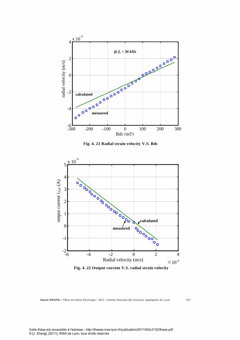
Jiawei ZHANG / Thèse en Génie Electrique / 2011 / Institut National des Sciences Appliquées de Lyon 107
-300 -200 -100 0 100 200 300 -6
-4
-2
0
2
4 x 10
-4
Bdc (mT)
radi
al v
eloc
ity (m
/s)
measured
@ fr = 36 kHz
calculated
Fig. 4. 21 Radial strain velocity V.S. Bdc
-6 -4 -2 0 2 4
×10-4
-2
-1
0
1
2
3
4
5 x 10
-4
Radial velocity (m/s)
outp
ut c
urre
nt i T
OT (
A)
measured
calculated
Fig. 4. 22 Output current V.S. radial strain velocity
Cette thèse est accessible à l'adresse : http://theses.insa-lyon.fr/publication/2011ISAL0132/these.pdf © [J. Zhang], [2011], INSA de Lyon, tous droits réservés

Jiawei ZHANG / Thèse en Génie Electrique / 2011 / Institut National des Sciences Appliquées de Lyon 108
Comparison between measured radial velocity by Eq.(4.83) and its
calculated value against dc magnetic field at fr has been shown in Fig. 4. 21.
It presents the good agreement between measured and calculated results. Ex-
perimental Sv shows a good linear variation. Finally, in Fig. 4. 22, TOTi is
linearly dependent of the velocity Sv , and is consistent with theoretical TOTi
calculated by Eq. (4.80).
4.5 Conclusion
In summary, we have observed that the best ME voltage coefficient
is given by the trilayered sample of (PU+2wt%Fe3O4/PVDF/
PU+2wt%Fe3O4), presenting a voltage coefficient is 75.33V/m-Oe, which is
greater than that obtained with the other sample as well as that obtained for
the monolayer consisited of PU+x% magnetic particles. A model based on a
driven damped oscillation system, to evaluate and study the influence of the
first and second-order ME coefficients on the dc magnetic field-induced
phase switching phenomenon, has been developed.
On the other hand, it is experimentally shown that ac magnetic field
induce eddy currents and the presence of applied dc magnetic field generate
Lorentz forces in the metal electrodes acting on piezoelectric compounds
such as PZT unimorph bender, single sheet PVDF film and PZT ceramic disc.
A magnetically induced piezoelectric current is obtained at the sample elec-
trodes and is the result of the product property between magnetic forces and
piezoelectricity. In this case, the ME coupling does absolutely not require
magnetic component, compared with ME effect originating from the product
property between magnetostriction and piezoelectricity (laminate compos-
ites).The major difference with previously published ME coupling implying
Lorentz forces and piezoelectric effect is that there is no need of current sup-
ply directly with connecting wires. The eddy currents in silver electrodes are
Cette thèse est accessible à l'adresse : http://theses.insa-lyon.fr/publication/2011ISAL0132/these.pdf © [J. Zhang], [2011], INSA de Lyon, tous droits réservés

Jiawei ZHANG / Thèse en Génie Electrique / 2011 / Institut National des Sciences Appliquées de Lyon 109
sufficient to generate Lorentz forces. The ME response is linear with Hdc,
contrary to magnetostrictive composites, which is very interesting for dc
magnetic field detection applications. Besides, the similar ME result is ob-
served in single piezoelectric PVDF film. Its mechanical model has bee testi-
fied by the measured ME result. Thus, the eddy current induced magnetoelec-
tric effect is expected to be observable in piezoelectric ceramics and
polymers, provided their electrodes are subjected to ac magnetic flux.
Cette thèse est accessible à l'adresse : http://theses.insa-lyon.fr/publication/2011ISAL0132/these.pdf © [J. Zhang], [2011], INSA de Lyon, tous droits réservés

Jiawei ZHANG / Thèse en Génie Electrique / 2011 / Institut National des Sciences Appliquées de Lyon 110
Chapter 5. Electrostrictive performance of the charged cellular PP
5.1 Introduction
After corona poling, there are a number of the charges injected in the
cellular PP. The charge storage ability of electrets plays an important part of
the application of electromechanical-transducer. Thus, some experiments
need to be undergone to examine the charge storage mechanism. Based on
the results of the surface potential decay test, TSDC and DSC experiments
described in this chapter, the charge retain ability and deposit situation of
cellular PP after corona poling has been examined. Then, it is used to explain
the enhanced electrostrictive effect of the charged sample. A mathematic
model which can explain the increase in electrostrictive coefficient and rela-
tive permittivity has been established.
Cette thèse est accessible à l'adresse : http://theses.insa-lyon.fr/publication/2011ISAL0132/these.pdf © [J. Zhang], [2011], INSA de Lyon, tous droits réservés

Jiawei ZHANG / Thèse en Génie Electrique / 2011 / Institut National des Sciences Appliquées de Lyon 111
5.2 Charge storage mechanism analysis on the charged cellular PP
5.2.1 Surface potential decay tendency
The industrial manufactured cellular PP film has two distinct sur-
faces: one is very smooth and another is rougher. Fig. 5. 1 is plotted with the
surface potential normalized by initial surface potential V(0) against the total
measurement time (500s), where the smooth and rough surfaces are exposed
to corona treatment respectively.
0 100 200 300 400 50092
93
94
95
96
97
98
99
100
time(s)
Nor
mal
ized
surfa
ce p
oten
tial (
%)
Charged on the Smooth Surface
Charged on the Rough Surface
Fig. 5. 1 A comparison of the normalized surface potential (V(t)/V(0)) between two
charged surfaces of different roughness.
It was found that the initial surface potential V(0) for both surfaces
was approximately the same at the beginning of the measurement: -4 kV, for
Cette thèse est accessible à l'adresse : http://theses.insa-lyon.fr/publication/2011ISAL0132/these.pdf © [J. Zhang], [2011], INSA de Lyon, tous droits réservés

Jiawei ZHANG / Thèse en Génie Electrique / 2011 / Institut National des Sciences Appliquées de Lyon 112
the sample charged on the rough surface and the same value for the sample
charged on the smooth side. On the contrary, the normalized surface potential
decay rate for the smooth surface (0.7 % from 0s to 500s) was much lower
than for the rough surface (8%).
The decay of the surface potential was more pronounced for the
rough surface due to its contact area with air being larger than that of the
smooth surface. Consequently, more surface charges could be released versus
time. The effect of the samples’ roughness has been already mentioned in an-
other study [5]. This experiment reveals that the roughness of the cellular PP
does not affect the charge injection as the same surface potential is observed,
but affects its surface potential decay quantitatively. Consequently, cellular
PP with corona poling on the smooth surface was applied in the following
experiments.
5.2.2 Charge storage analysis through TSDC measurements
Fig. 5. 2 shows the TSDC current versus the temperature. For the
non-charged sample, no TSDC current was measured from 23°C to 140°C.
For the corona charged samples, on the other hand, three peaks can be clearly
seen on the curve: the first one - designated the peak a - at 60°C with a
maximum current value of 5pA; the second peak - designated the peak b - at
86°C with a maximum current value of 10pA, and the third one - designated
the peak c - at 128°C with a maximum current of 4pA. The two former peaks
have been mentioned in a previous investigation [5]. As expected for the non-
charged samples, no TSDC peak was observed due to the fact that PP is a di-
electric for which no free charge exists without corona poling treatment. In
contrast, for the charged samples, the existence of peaks was evidence of
charges having been injected within the sample during the corona treatment
and of these charges having been maintained at different depth within the
sample after the treatment [106, 131, 150, 151]. Specifically, the second and
Cette thèse est accessible à l'adresse : http://theses.insa-lyon.fr/publication/2011ISAL0132/these.pdf © [J. Zhang], [2011], INSA de Lyon, tous droits réservés

Jiawei ZHANG / Thèse en Génie Electrique / 2011 / Institut National des Sciences Appliquées de Lyon 113
the third peaks which are more diffuse clearly concern a thermal activated
phenomenon of free charges displacement and should concern electron that
are more deeply injected within the samples. Then, by using Eq.(3.1), the ab-
solute value of the total quantity of injected charges was found to be equal to
23.9 nC.
Fig. 5. 2 TSDC current measurements versus temperature for non-charged and
charged cellular PP
5.2.3 Charge quantity comparison among different applied corona voltage
In order to investigate the influence of different corona voltage of
the discharge needle on the quantity of injected charge. We apply high-
voltage from -15kV to -30kV, and calculate the quantity based on the TSDC
experiment results in each case. Fig. 5. 3 depicts the variation of released
charges versus temperature after the corona treatment for various corona
Cette thèse est accessible à l'adresse : http://theses.insa-lyon.fr/publication/2011ISAL0132/these.pdf © [J. Zhang], [2011], INSA de Lyon, tous droits réservés

Jiawei ZHANG / Thèse en Génie Electrique / 2011 / Institut National des Sciences Appliquées de Lyon 114
voltages applied on the needles. This quantity of charges was calculated
through integration of the measured TSDC current.
40 60 80 100 120 1400
0.5
1
1.5
2
2.5 x 10⁻⁸
Temperature (oC)
Qua
ntity
of c
harg
es (C
)
-30kV corona charged film-25kV corona charged film-20kV corona charged film-15kV corona charged film
Fig. 5. 3 The total quantity of charges in cellular PP under the corona voltage from -
30kV to -15kV.
In these curves, we can observe that a smooth increase in released
charges with a step of almost from 60°C to 100°C. This step correspondes to
the two diffuse peaks denoted a and b, which can be also observed in the
curve of TSDC result. This smooth increase phase indicate that the charge
stored in the shallow energy traps of cellular PP released slowly with the in-
crease in temperature. Then, the total quantity of released charges versus
temperature, which is equal to the charges injected by the corona process,
was found to increase with the corona voltage applied on the needles from
9.1 nC at -15 kV to 23.9 nC at -30 kV. As previously explained, the charges
that were more deeply injected were progressively released, leading to the
smooth increase in the charge.
Cette thèse est accessible à l'adresse : http://theses.insa-lyon.fr/publication/2011ISAL0132/these.pdf © [J. Zhang], [2011], INSA de Lyon, tous droits réservés

Jiawei ZHANG / Thèse en Génie Electrique / 2011 / Institut National des Sciences Appliquées de Lyon 115
As expected, the quantity of released charges, which was equal to
the quantity of injected charges, increased as the potential applied to the nee-
dles was raised. This phenomenon was imposed by the fact that a higher co-
rona voltage helps to enhance Paschen's breakdown [106] of the air between
the needles and the sample, as well as that of the voids inside the cellular PP.
Therefore, the quantity of charges corresponded to the various applied volt-
ages in corona discharge.
5.3 Analysis on crystallinity
5.3.1 Measured DSC traces of cellular PP
Fig. 5. 4 shows the thermal behavior, as measured by DSC experi-
ments, of non-charged and -30kV-charged cellular PP. For the two samples
and for the first thermal cycle on the charged cellular PP, a first peak can be
observed at 127°C. After integration of the heat flow, the corresponding en-
thalpy, ∆H, was equal to 0.82 J/g for the non-charged sample and 2.38 J/g for
that charged at -30 kV. For both materials, a second peak was observed at
169°C. The corresponding enthalpy was equal to 62.57 J/g and 75.49 J/g re-
spectively for the non-charged and charged materials. During the cooling, a
third peak was observed for the two samples at a same temperature of 114°C.
The enthalpy value was 72.69 J/g for the non-charged sample and 73.2 J/g for
the -30 kV charged sample.
For the second thermal cycle applied on the charged sample, a DSC
trace close to that of the non-charged sample can be observed, showing that
this sample has recovered the properties exhibited before the corona treat-
ment. As a consequence, the large increase in the enthalpy for the first peak
Cette thèse est accessible à l'adresse : http://theses.insa-lyon.fr/publication/2011ISAL0132/these.pdf © [J. Zhang], [2011], INSA de Lyon, tous droits réservés

Jiawei ZHANG / Thèse en Génie Electrique / 2011 / Institut National des Sciences Appliquées de Lyon 116
and the slight one for the two other peaks can be unambiguously attributed to
the corona injection.
50 100 150 200-1.5
-1
-0.5
0
0.5
1
1.5
2
2.5
Temperature(oC)
Hea
t Flo
w (
mW
/mg)
Non-charged Cellular PPCharged Cellular PP 1st RunCharged Cellular PP 2nd Run
Third peak
First peakβ phase
Second peakα phase
Fig. 5. 4 DSC traces of charged and non-charged cellular PP
As previously reported, commercial PP is mainly composed of two
crystalline phases named as α phase and β phase [152]. The melting tempera-
tures of the major α phase and of the β phase are generally given around
160°C and around 130°C respectively [152, 153]. Consequently, in good
agreement with these results, the first peak observed in DSC at 127°C is be-
lieved to be due to the β phase melting and the second one observed at 169°C
is due to the α phase melting. The third peak observed during the cooling
procedure at 114°C is due to the crystallization of the melting.
By using the following Eqs.(5.1) and (5.2), the percentage of crystal-
linity of β phase (Hβ) and α phase (Hα) within the sample can be calculated
by assuming that the melting enthalpy of 100% α- and β-crystalline phase is
178 J/g and 168J/g respectively [142, 152, 153]. The obtained results are
summarized in Tab. 5. 1. Even though the mechanism is not well understood,
Cette thèse est accessible à l'adresse : http://theses.insa-lyon.fr/publication/2011ISAL0132/these.pdf © [J. Zhang], [2011], INSA de Lyon, tous droits réservés

Jiawei ZHANG / Thèse en Génie Electrique / 2011 / Institut National des Sciences Appliquées de Lyon 117
the corona injection has clearly increased the content of the β phase and
slightly increased the content of the α phase.
( )(%) 100mH H Hαα = ∆ ∆ × (5.1)
( )(%) 100mH H Hββ = ∆ ∆ × (5.2)
The peak a and b observed on the TSC curve did not correspond to
any event on the DSC diagram. As a consequence, it is reasonable to assume
that they have no link with the melting temperature of the α and β phases.
These peaks are probably due to the space charges which are not deeply in-
jected in the polymer. The peak c observed on the TSC curve occurs at a
temperature closed to the melting temperature of the β phase and is probably
due to the release of the trapped charges at the β phase interface.
Tab. 5. 1 Calculated percentage crystallinity of β phase and α phase
Material β-crystalline phase
α-crystalline phase
Non-charged cellular PP 0.49% 35.2%
-30kV-charged PP 1.42% 42.4%
In addition, a corona discharge treatment gives rise to the incorpora-
tion of various chemical groups containing oxygen into the films, mainly
C=O [101], which was in agreement with of XPS (X-ray Photoelectron Spec-
troscopy) measurement result in Ref. [121]. The main polymer chains were
broken and rearranged by macromolecular motions, and the dipole moment
was formed within the film [154]. Consequently, the melting enthalpy for the
-30kV-corona-charged sample was higher than the corresponding value for
the non-charged material.
Cette thèse est accessible à l'adresse : http://theses.insa-lyon.fr/publication/2011ISAL0132/these.pdf © [J. Zhang], [2011], INSA de Lyon, tous droits réservés

Jiawei ZHANG / Thèse en Génie Electrique / 2011 / Institut National des Sciences Appliquées de Lyon 118
5.3.2 Wide angle X-ray Differaction spectra of cellular PP
In addition, the Wide Angle X-ray Diffraction (WAXD) spectra are
shown in following Fig. 5. 5 and the area of each peak of 2θ were listed in
Tab. 5. 2. WAXD measurements have been performed at MATEIS Labora-
tory, INSA Lyon. The slight but evident increase in the integral intensity of
WAXD peaks of corona-charged cellular PP was an evidence of increased
crystallinity at the surface of charged sample [152].
Fig. 5. 5 WAXD spectra of non-charged and corona-charged cellular PP
Cette thèse est accessible à l'adresse : http://theses.insa-lyon.fr/publication/2011ISAL0132/these.pdf © [J. Zhang], [2011], INSA de Lyon, tous droits réservés

Jiawei ZHANG / Thèse en Génie Electrique / 2011 / Institut National des Sciences Appliquées de Lyon 119
As shown in Fig. 5. 5 and Tab. 5. 2., concerning the α peak, we ob-
serve a small increase of the peaks of intensity and a small decrease of the
FWHH (Full Width at the Half-Height) which were in good agreement with
the enthalpy increase of the α phase contents observed on DSC.
Tab. 5. 2 Integral of intensity of cellular PP at each WAXD peaks V.S. 2θ
2θ (deg) Peak name Integral of intensity Non-charged cellu-
lar PP
Integral of intensity Corona-charged cel-
lular PP
14.2 (110) α 73.17 89.81
17 (040) α 210.6 209.3
18.6 (130) α 23.44 32.56
25.6 (140) α 27.92 32.94
5.4 Electrostrictive performance of charged cellular PP
5.4.1 Electrostriction measurements results
Tab. 5. 3 gives the low electric field (0.5 V/mm) permittivity at 0.1
Hz, i.e., the same frequency of the applied electric field for strain measure-
ments. It can be seen that the corona treatment also almost doubled the value
of the permittivity, probably by inducing a space charge polarization that
contributed to the permittivity value [91, 106]. This is also called interfacial
polarization and is present in polymers having large structural in homogenei-
ties. If the density of electric charges in the material is increased by corona
Cette thèse est accessible à l'adresse : http://theses.insa-lyon.fr/publication/2011ISAL0132/these.pdf © [J. Zhang], [2011], INSA de Lyon, tous droits réservés

Jiawei ZHANG / Thèse en Génie Electrique / 2011 / Institut National des Sciences Appliquées de Lyon 120
poling, the low frequency interfacial polarization is enhanced and permittiv-
ity may be significantly higher, as observed. Besides, the increase in the
crystallinity of PP films induced by charge injection may also contribute to
the better dielectric response, since this latter primarily originates from the
crystalline phase of the polymer [3].
Tab. 5. 3 Relative permittivity of tested cellular PP at 0.1 Hz
Material εr (0.1Hz)
Non-charged cellular PP 1.20
-30kV-charged PP 2.31
2 4 6 8 10 12 14 16x 1013
-0.5
-0.4
-0.3
-0.2
-0.1
0
E2 (V2/m2)
Stra
in (%
)
Charged cellular PPNon-charged cellular PP
Fig. 5. 6 Strain behavior of the charged and non-charged cellular PP as the function of
the square of the driving electric field.
Fig. 5. 6 presents curves of strain versus the square of the electrical
field for the non-charged and the -30kV-charged samples, at 0.1 Hz. For both
Cette thèse est accessible à l'adresse : http://theses.insa-lyon.fr/publication/2011ISAL0132/these.pdf © [J. Zhang], [2011], INSA de Lyon, tous droits réservés

Jiawei ZHANG / Thèse en Génie Electrique / 2011 / Institut National des Sciences Appliquées de Lyon 121
materials, a linear dependence is observed confirming that the applied elec-
tric field dependence of the strain is quadratic. This result clearly indicates
that the origin of the strain was mainly electrostrictive and/or induced by
Maxwell stress effect. As a consequence, S3 can be expressed according to:
2
3 33 3S M E∗= ⋅ (5.3)
By using the permittivity data from Tab. 5. 3 together with Young
modulus of cellular PP measured in our laboratory (1GPa), the percentage
contribution of the Maxwell effect (–(εr.ε0 /Y) E32) to the strain was found
equal to 0.081% for the non-charged PP and 0.07% for the -30 kV-charged
material. Consequently, the Maxwell effect can be neglected and the overall
contribution to the strain is clearly due to the pure electrostrictive effect.
The apparent electrostriction coefficient may, be evaluated in both
cases with the formula: M33*=S3/E3
2, giving a value of 1.3×10⁻¹⁷ m²/V² for the
non-charged sample and 3.1×10⁻¹⁷ m²/V² for its -30kV-charged counterpart..
The charge-related electrostrictive coefficient, Q33, can be calculated using
M33=Q33ε02(εr-1)2 and gives the value 4.2×10⁶ m4C-2 for the non-charged PP
and 0.23×10⁶ m4C-2 for the charged material. These values have been con-
firmed by a direct polarization measurement when performing the strain ver-
sus electric field experiment and the Q33 calculation from S3=Q33P3². Interest-
ingly, charge injection with corona poling decreases the Q33 coefficient of PP
films, like conductive fillers such as carbon black (CB) incorporated in elec-
trostrictive polymer matrices like polyurethane (PU) films [155]. But in this
CB/PU composite system, global electrostrictive response (M33 coefficient) is
also enhanced.
It is worthwhile to note that the observed increase in the strain is
mainly due to an increase in the permittivity and that corona treatment was
able to greatly enhance the ability of the cellular PP to become electrically
strained [9, 91, 106]. The enhanced strain in thin film is a consequence of
Cette thèse est accessible à l'adresse : http://theses.insa-lyon.fr/publication/2011ISAL0132/these.pdf © [J. Zhang], [2011], INSA de Lyon, tous droits réservés

Jiawei ZHANG / Thèse en Génie Electrique / 2011 / Institut National des Sciences Appliquées de Lyon 122
nonuniform space-charge distribution across the thickness direction [156].
Due to the corona poling, the charges injected from the non-electroded sur-
face were trapped in the film and then, formed a space charge layer, which
augmented the electrostatic capacitance of charged sample [157]. Then, since
the effect of the poling field was to orient the molecules of charged PP, the
dipole moments pointed in the same direction, which would lead to electro-
static interactions between neighboring additives. The presence of an appro-
priate space-charge between two additives would force that dipole (additive)-
charge- dipole (additive) system behaves as a unit. The combined mass and
volume of such a unit would be much greater than a single dipole, thus hin-
dering reorientation increasing the amount of stress [158]. Also the new di-
pole-charge-dipole system can be responsible for the enhanced electrostric-
tive effect in the poled system. Therefore, the charge in the bulk of the
polymer would correlate the motion of the supplementary dipoles [130]. In
addition, the charge storage capability of polymer electret material is also de-
termined by the chemical nature of the polymer [18].
Fig. 5. 7 The oxidized polar groups generated in corona poling [101, 156]
As shown in Fig. 5. 7, N.Sellin et al. analyzed oxidized polar groups
on the film surface by infrared spectroscopy (FTIR/ATR) technique and con-
Cette thèse est accessible à l'adresse : http://theses.insa-lyon.fr/publication/2011ISAL0132/these.pdf © [J. Zhang], [2011], INSA de Lyon, tous droits réservés

Jiawei ZHANG / Thèse en Génie Electrique / 2011 / Institut National des Sciences Appliquées de Lyon 123
firmed the presence of oxidized polar groups in corona poled PP films,
mainly, C=O, C-O and COH [101, 159].
5.4.2 Electrical modelling based on charged cellular PP
Furthermore, based on the experimental data and interpretations
given in Refs.[6, 14], in which space charge distribution of PP films has been
investigated, a simplified model of charged cellular PP is proposed, in order
to explain the beneficial effect of injected charges on the dielectric properties.
In Fig. 5. 8, ρ is the charge density (ρ<0), whose value is assumed to
be equal in every layer. Divergence of electric field E can be obtained from
Maxwell’s equations:
ερ
=∇E (5.4)
where ε is the permittivity. Then,
ερ
=dxdE
(5.5)
Fig. 5. 8 Simplified model of corona-charged cellular PP
Cette thèse est accessible à l'adresse : http://theses.insa-lyon.fr/publication/2011ISAL0132/these.pdf © [J. Zhang], [2011], INSA de Lyon, tous droits réservés

Jiawei ZHANG / Thèse en Génie Electrique / 2011 / Institut National des Sciences Appliquées de Lyon 124
Electric field can be expressed as:
( )txExxE <+= )0()(ερ
( )texttExE −<<+=ερ)0()(
( )extexeExE <<−−+= )()0()(ερ
(5.6)
And then by integrating of the electrical field along the thickness of
the sample, we got:
∫∫ −=)(
)0(0
eV
V
e
dVldE (5.7)
We got the potential V on the sample which can be expressed by
eEteteVV )0()()()0( +−=−ερ (5.8)
Together with V(0)-V(e)=Q/C and Q=σ0S, capacitance of sample is
calculated by
)(0
teteSCcellularPP
−+=
εσρ
ε
(5.9)
For the non-charged film, ρ is around to be null and CcellularPP= ε.S/e.
For charged sample, as ρ <0 and σ0>0:
0
( )e et e tρε σ ε ε
+ − < (5.10)
Cette thèse est accessible à l'adresse : http://theses.insa-lyon.fr/publication/2011ISAL0132/these.pdf © [J. Zhang], [2011], INSA de Lyon, tous droits réservés

Jiawei ZHANG / Thèse en Génie Electrique / 2011 / Institut National des Sciences Appliquées de Lyon 125
and
charged mon-charged
PP PPcellular cellularC C> (5.11)
Consequently, capacitance and relative permittivity of charged cellu-
lar PP are greater than non-charged film, which lead to increase in strain in
charged film as well.
5.5 Conclusion
In this part, we have demonstrated that after corona poling, electro-
strictive response of cellular PP was enhanced, which is due to the non-
uniform distribution of free injected charge and its displacement. Increase in
the electrical-field-induced strain and permittivity were explained experimen-
tally by using TSC, DSC and permittivity measurements, as well as a simple
dielectric model. Larger strain responses and higher permittivity were ob-
served for the charged sample as opposed to for the neat one. It appears that
the injected charges contributed to induce a space charge polarization within
the samples which highly contributed to the permittivity and the induced
strain.
Cette thèse est accessible à l'adresse : http://theses.insa-lyon.fr/publication/2011ISAL0132/these.pdf © [J. Zhang], [2011], INSA de Lyon, tous droits réservés

Jiawei ZHANG / Thèse en Génie Electrique / 2011 / Institut National des Sciences Appliquées de Lyon 126
Chapter 6. Conclusions and future work
The motivation for the work was twofold. Firstly, we have studied
on magnetoelectric performance of the laminated polymer composites and es-
tablishing mathematic models of each case. Secondly, the charge storage
mechanism and the resulting enhanced electrostrictive effect on the cellular
polypropylene after its corona poling has been analysed.
6.1 Main conclusions on magnetoelectric effect
In our works, we report on the direct magnetoelectric effect ob-
served in bi- and trilayered polymers consisting of polyvinylidene fluoride
(PVDF) and polyurethane (PU) filled with magnetically hard magnetite
Fe3O4 or Terfenol-D(TeD) magnetostrictive material. A model, based on a
driven damped oscillation system, has been developed to evaluate and study
the influence of the first and second-order ME coefficients on the dc magnet-
ic field-induced phase switching phenomenon between dynamic ME current
and the applied ac magnetic field.
Aside from ME effects in multi-layer laminated composite materials,
another novel and better performance of ME behaviour or developments indi-
cating future fields of ME effect research have been discussed in this paper.
The presented ME effect is an alternative to the product property between
magnetostriction and piezoelectricity and is rather based on the product prop-
Cette thèse est accessible à l'adresse : http://theses.insa-lyon.fr/publication/2011ISAL0132/these.pdf © [J. Zhang], [2011], INSA de Lyon, tous droits réservés

Jiawei ZHANG / Thèse en Génie Electrique / 2011 / Institut National des Sciences Appliquées de Lyon 127
erty between Lorentz forces and piezoelectricity. The originality of this ME
coupling is that Lorentz forces are located in the metal electrodes of the pie-
zoelectric material and originate from eddy currents induced by ac magnetic
flux within them. By this way, a ME coupling is finally achieved with only
one piezoelectric material, in which no magnetic phase is required, and no di-
rect ac current supply on the sample is necessary, eddy currents in electrodes
are sufficient to generate Lorentz forces. Of course, optimal ac field orienta-
tion is required, i.e., ac magnetic field must be applied perpendicular to the
electrodes to reach maximum flux. Consequently largest eddy currents mag-
nitude and stress and strain magnitude may be achieved, yielding large direct
piezoelectric response.
Then, the similar ME effect can be obtained using a PVDF film and
a simple piezoelectric ceramic disc. Besides, owing to the circular shape of
the disc, calculation of the Lorentz forces, and associated stresses can be re-
alized, which was not the case for the rectangular unimorph bender in the
former ME experiments. So, the measured output magnetoelectric current of
a single piezoelectric disc was successfully modelled using piezoelectric
equations providing the inductively coupled voltage between the electrodes
of the ceramic is taken into account. The total output current can be attrib-
uted to three important sources: 1) The stress induced by the eddy currents
within the metal electrodes through the Lorentz force effect is transferred to
the piezoelectric layer and generates electric charges. This stress is increased
by the dc bias field appliance. 2) The well known ME coupling based on a
mechanical interaction between magnetostrictive and piezoelectric layers in
laminate composites. 3) The dielectric current generated by the parasitic
voltage induced by the ac magnetic flux through the closed contour of the
experimental loop, is an inductively coupled voltage between the electrodes
of the samples which can be explained by the Lenz and Faraday’s Laws.
It is found that a good correlation between theoretical and experi-
mental results can be got from the model. The ME response is linear with the
Cette thèse est accessible à l'adresse : http://theses.insa-lyon.fr/publication/2011ISAL0132/these.pdf © [J. Zhang], [2011], INSA de Lyon, tous droits réservés

Jiawei ZHANG / Thèse en Génie Electrique / 2011 / Institut National des Sciences Appliquées de Lyon 128
magnitude of dc magnetic field. In addition, combined radial velocity meas-
urements validated the contribution of both radial stress and magnetically in-
duced electric field. Finally, it was found that anisotropic dc field sensing
can also be sensitively achieved at room temperature with only a single pie-
zoelectric ceramic.
6.2 Main conclusions on electrostrictive effect
In view of the importance that the cellular PP electret in the field of
EAP. We reported on our ongoing investigations of dipolar-charged cellular
PP electrets. The results of surface potential decay tendency showed that the
surface roughness influenced corona poling effect. The sample charged on
smooth surface could keep surface charge for a longer time than the sample
charged on its rough surface. Then, the results of electrostrictive effect dem-
onstrated that after corona poling, electrostrictive response of cellular PP was
enhanced. Increase in the electrical-field-induced strain and permittivity were
explained experimentally by using TSC, DSC and permittivity measurements,
as well as a simple dielectric model. It was shown with TSC measurements
that the corona treatment at room temperature could inject charges at various
depths, which were the main factor that enhanced electromechanical response
of the -30 kV-charged sample. From permittivity measurements and electri-
cal-field-induced strain experiments, higher permittivity and larger strain re-
sponses were observed for the charged sample as opposed to for the neat one.
It appeared that the injected charges contributed to induce a space charge po-
larization within the samples which highly contributed to the permittivity and
consequently the induced strain. In addition, by means of DSC measurements,
from the chemical viewpoint, it was demonstrated that the corona treatment
increased the crystallinity of cellular PP, which is consistent with the in-
Cette thèse est accessible à l'adresse : http://theses.insa-lyon.fr/publication/2011ISAL0132/these.pdf © [J. Zhang], [2011], INSA de Lyon, tous droits réservés

Jiawei ZHANG / Thèse en Génie Electrique / 2011 / Institut National des Sciences Appliquées de Lyon 129
crease in the dielectric response. Finally, a simplified model based on space
charges with distinct polarity trapped in the vicinity of sample surfaces was
also proposed in order to explain the increase in the effective permittivity and
strain after corona poling.
6.3 Future work
Based on the previous researching experiences on the magenetoelec-
tric effect of the composite materials, it would be promising for application
that ac magnetic flux inducing eddy current within the electrodes of the other
soft piezoelectric polymer. Comparing with stiff piezoelectric ceramic, the
polymer has many merits, such as simpler structure, easier to fabricate and it
is not as fragile as PZT unimorph bender. However, the design idea and mag-
netoelectric response of the unimorph bender in this work are precious and
will promise to be applied widely. Furthermore, In order to develop it for
practical applications, the set-up of the ME sensor must be improved to be-
come more compact and portable, probably by using small permanent mag-
nets to replace the giant electromagnets in ME experiment.
Because the Lorentz force induced magnetoelectric effect in uni-
morph bender and PVDF film is caused by eddy current within their elec-
trodes, the current density will influence their magnetoelectric responses and
vibrating velocity. Using different metal as electrodes with various conduc-
tivities should change the eddy current density and cause the different bend-
ing modes of benders. Thus, the ME effect and actuation mode of samples
probably can be influenced by this way.
Since the complete mechanism of the electrostriction enhancement is
not yet fully understood, other experiments and advanced technologies such
as Laser Induced Pressure Pulse (LIPP) method, Photo Stimulated Current
(PSC) method should be used to test the space-charge distribution in cellular
Cette thèse est accessible à l'adresse : http://theses.insa-lyon.fr/publication/2011ISAL0132/these.pdf © [J. Zhang], [2011], INSA de Lyon, tous droits réservés

Jiawei ZHANG / Thèse en Génie Electrique / 2011 / Institut National des Sciences Appliquées de Lyon 130
polymer, in order to enhance the understanding of space-charge storage
mechanism in the sample. In addition, using corona discharge set up and
forming the dipole within the composite embedded with magnetic particles
seems to be another novel source of magnetoelectric effect, which is also the
important link between two research topics in this thesis.
Furthermore, the experiment on the high-voltage corona charged
polymer promise to be put into application such as micro electret generator
that can retain the charges over an extensive period of time.
Cette thèse est accessible à l'adresse : http://theses.insa-lyon.fr/publication/2011ISAL0132/these.pdf © [J. Zhang], [2011], INSA de Lyon, tous droits réservés

Jiawei ZHANG / Thèse en Génie Electrique / 2011 / Institut National des Sciences Appliquées de Lyon 131
List of figures
Fig. 1. 1 Direct ME effect of single-phase TbMnO3: Electric polarization
induced by an applied magnetic filed [42]. ................................... 16
Fig. 1. 2 Converse ME Effect of BiFeO3: magnetization changed by an
applied electric field. (Reported by T. Zhao, et al, Nature Materials,
2006) [41] ................................................................................... 17
Fig. 1. 3 Schematic illustration of three common types of bulk composites (a)
1-3 fiber/rod composite, (b) 0-3 particulate composite, (c) 2-2
laminate composite [18]............................................................... 18
Fig. 1. 4 Schematic illustration of two types of ME effect in laminate
composites (a) MEH effect (b) MEE effect [63] ............................. 22
Fig. 1. 5 Magnetostrictive/piezoelectric laminate composite [64] ............... 23
Fig. 1. 6 A ME composite of a brass ring and a PZT disk with Cartesian
coordinates [65] ........................................................................... 24
Fig. 1. 7 A dc ME sensor in the Cartesian coordinate system proposed by
Leung C.M. et. al. [66] F1 are Lorentz forces transversely applied to
the piezoelectric PMN-PT plate ................................................... 25
Fig. 1. 8 Magetoelectric laminte composite using TERFENOL-D and PZT
discs. (a) Schematic structure; (b) photograph of the sample [38] 26
Fig. 1. 9 EAP gripper grabs rocks and works as artificial muscle [76] ........ 28
Fig. 1. 10. Different types of deformation of dielectrics [80] ...................... 29
Fig. 1. 11 Orientation of dipoles under electric field [17, 87] ..................... 30
Fig. 1. 12 SEM image of cellular PP after pressure expansion [14] ............. 35
Cette thèse est accessible à l'adresse : http://theses.insa-lyon.fr/publication/2011ISAL0132/these.pdf © [J. Zhang], [2011], INSA de Lyon, tous droits réservés

Jiawei ZHANG / Thèse en Génie Electrique / 2011 / Institut National des Sciences Appliquées de Lyon 132
Fig. 1. 13 Development of the negative electric charge avalanche from the
cathode [108, 117]. ...................................................................... 36
Fig. 2. 1 The fabrication procedure of composite solution .......................... 43
Fig. 2. 2 The fabrication procedure from composite solution to PU composite
films............................................................................................ 44
Fig. 2. 3 Schematic diagram of the rectangular shape piezoelectric unimorph
bender subjected to ac and dc magnetic fields. ............................. 47
Fig. 2. 4 Photograph of the ME experimental test bench ............................. 48
Fig. 2. 5 Schematic drawing of the experimental system of ME sensor and its
vibration velocity measurement ................................................... 48
Fig. 2. 6 Detailed schematic drawing PZT unimorph sensor between two
magnetic poles............................................................................. 49
Fig. 2. 7 Schematic diagram of the rectangular shape PVDF film subjected to
ac and dc magnetic fields ............................................................. 50
Fig. 2. 8 Schematic diagram of the piezo-ceramic disc in ME measuring
system ......................................................................................... 52
Fig. 3. 1 The corona discharge setup. ........................................................ 55
Fig. 3. 2 (a) photograph of the surface potential test setup (b) Schematic
representation of the surface potential measurement setup [140] ... 56
Fig. 3. 3 (a) Photograph Test bench of Young’s modulus measurement;
(b)Schematic of measuring system of Young’s modulus ............... 58
Fig. 3. 4 (a) The experimental process of the TSC technique; (b) Schematic
of the TSDC technique ................................................................ 59
Fig. 3. 5 Scheme of DSC instrument [143] ................................................. 61
Fig. 3. 6 The electrostrictive coefficient measurement setup ....................... 62
Fig. 4. 1 Experimental variation of the square of the ME current 2 ( )ME dcI H of
the multilayer composites versus the (dc) magnetic field. ............. 67
Cette thèse est accessible à l'adresse : http://theses.insa-lyon.fr/publication/2011ISAL0132/these.pdf © [J. Zhang], [2011], INSA de Lyon, tous droits réservés

Jiawei ZHANG / Thèse en Génie Electrique / 2011 / Institut National des Sciences Appliquées de Lyon 133
Fig. 4. 2 Variation of the total magnetoelectric coefficient of the multilayered
composites versus the (dc) magnetic field. ................................... 69
Fig. 4. 3 A schematic of the structure of the sandwiched composites, (a)
bilayer sample. (b) trilayer sample; .............................................. 70
Fig. 4. 4 Schematic presentation of magnetic particulate in the
magnetostrictive layer under magnetic field effect. ....................... 71
Fig. 4. 5 Variation of the phase shift between the ME current and the (ac)
magnetic field versus the dc magnetic field. ................................. 77
Fig. 4. 6 The influence of the real part of the linear ME coefficient 'pα
( ''pα , '
pβ , ''pβ were taken as constant values)...................................... 78
Fig. 4. 7 The effect of the imaginary part of the linear ME coefficient ''pα
( 'pα , '
pβ , ''pβ were taken as constant values). .................................... 79
Fig. 4. 8 The effect of the real part of the bilinear ME coefficient 'pβ (with
'pα , ''
pα , ''pβ taken as constant values.) .............................................. 80
Fig. 4. 9 The influence of the imaginary part of the bilinear ME coefficient ''pβ
(with 'pα , ''
pα , 'pβ taken as constant values.) ................................... 80
Fig. 4. 10 Schematic representation of the piezoelectric unimorph bender
subjected to ac and dc magnetic fields. Two configurations (① and
②) provide the ac field direction. ied is the eddy current loop within
the electrode ................................................................................ 83
Fig. 4. 11 dc field dependence of the algebraic magnetoelectric current
measured at the bending-mode resonance frequency (4.9 kHz) and
Hac=1 Oe, in the two configurations. ............................................ 86
Fig. 4. 12 (a) RMS voltage of PZT unimorph bender versus dc magnetic field
from -2400 Oe to +2400Oe (b) vibrating velocity of PZT unimorph
bender versus the same dc magnetic field ..................................... 88
Cette thèse est accessible à l'adresse : http://theses.insa-lyon.fr/publication/2011ISAL0132/these.pdf © [J. Zhang], [2011], INSA de Lyon, tous droits réservés

Jiawei ZHANG / Thèse en Génie Electrique / 2011 / Institut National des Sciences Appliquées de Lyon 134
Fig. 4. 13 (a) RMS voltage of PZT unimorph bender versus ac current in
conducting wire; (b) Vibrating velocity magnitude of PZT unimorph
bender versus ac current in conducting wire ................................. 89
Fig. 4. 14 Schematic of vibrating mode of PZT unimorph sensor ................ 90
Fig. 4. 15 dc magnetic induction dependence of ME current ....................... 93
Fig. 4. 16 Schematic representation of possible eddy current loops ............. 93
Fig. 4. 17 Schematic drawing of PZT ceramic disc in ac and dc magnetic
field ............................................................................................ 94
Fig. 4. 18 Infinitesimal Lorentz stress along radial direction induced by eddy
current density J and applied magnetic induction B ...................... 98
Fig. 4. 19 dc magnetic induction dependence of algebraic current magnitude.
................................................................................................. 101
Fig. 4. 20 Frequency dependence of radial velocity showing
electromechanical enhancement only in the vicinity of the resonance
frequency (36 kHz) .................................................................... 103
Fig. 4. 21 Radial strain velocity V.S. Bdc ................................................ 107
Fig. 4. 22 Output current V.S. radial strain velocity ................................. 107
Fig. 5. 1 A comparison of the normalized surface potential (V(t)/V(0))
between two charged surfaces of different roughness. ................ 111
Fig. 5. 2 TSDC current measurements versus temperature for non-charged
and charged cellular PP ............................................................. 113
Fig. 5. 3 The total quantity of charges in cellular PP under the corona voltage
from -30kV to -15kV. ................................................................ 114
Fig. 5. 4 DSC traces of charged and non-charged cellular PP ................... 116
Fig. 5. 5 WAXD spectra of non-charged and corona-charged cellular PP .. 118
Fig. 5. 6 Strain behavior of the charged and non-charged cellular PP as the
function of the square of the driving electric field. ..................... 120
Fig. 5. 7 The oxidized polar groups generated in corona poling [101, 156] 122
Fig. 5. 8 Simplified model of corona-charged cellular PP ......................... 123
Cette thèse est accessible à l'adresse : http://theses.insa-lyon.fr/publication/2011ISAL0132/these.pdf © [J. Zhang], [2011], INSA de Lyon, tous droits réservés

Jiawei ZHANG / Thèse en Génie Electrique / 2011 / Institut National des Sciences Appliquées de Lyon 135
List of tables
Tab. 1. 1ME voltage coefficient for some bulk composites materials [20, 28,
47-58]. ........................................................................................ 19
Tab. 1. 2 List of the leading EAP materials [77, 78] ................................... 28
Tab. 4. 1 Comparison between the calculated results of the different samples.
................................................................................................... 76
Tab. 4. 2 Different configurations of ME experiment on PZT unimorph
bender ......................................................................................... 83
Tab. 5. 1 Calculated percentage crystallinity of β phase and α phase ........ 117
Tab. 5. 2 Integral of intensity of cellular PP at each WAXD peaks V.S. 2θ 119
Tab. 5. 3 Relative permittivity of tested cellular PP at 0.1 Hz ................... 120
Cette thèse est accessible à l'adresse : http://theses.insa-lyon.fr/publication/2011ISAL0132/these.pdf © [J. Zhang], [2011], INSA de Lyon, tous droits réservés

Jiawei ZHANG / Thèse en Génie Electrique / 2011 / Institut National des Sciences Appliquées de Lyon 136
List of publications
1 GUIFFARD B., GUYOMAR D., BELOUADAH R. and ZHANG J. W.,
"Piezomagnetic losses in bilayered magnetostrictive/piezoelectric composites:
Effect of Terfenol-D content on the magnetoelectric susceptibility," Materials
Letters, 63, 2584-2586, 2009.
2 GUIFFARD B., GUYOMAR D., GARBUIO L., BELOUADAH R., ZHANG J.
W. and COTTINET P. J., "Eddy current induced magnetoelectricity in a
piezoelectric unimorph bender," Applied Physics Letters, 96, 044105, 2010.
3 GUIFFARD B., ZHANG J. W., GUYOMAR D., GARBUIO L., COTTINET P. -J.
and BELOUADAH R., "Magnetic field sensing with a single piezoelectric ceramic
disk: Experiments and modeling," Journal of Applied Physics,108, 094901, 2010.
4 BELOUADAH R., GUYOMAR D., GUIFFARD B. and ZHANG J.W., "Phase
switching phenomenon in magnetoelectric laminate polymer composites:
Experiments and modeling" Physica B: Condensed Matter. 406, 2821-2826, 2011
5 ZHANG J. W., LEBRUN L., GUIFFARD B., BELOUADAH R., GUYOMAR D.,
GARBUIO L., COTTINET P.-J. and QIN L., "Enhanced Electromechanical
Performance of Cellular Polypropylene Electrets Charged at High Temperature"
Journal of Physics D: Applied Physics. 44, 415403, 2011
6 ZHANG J. W., LEBRUN L., GUIFFARD B., COTTINET P.-J., GUYOMAR D.,
GARBUIO L. and BELOUADAH R., "Influence of corona poling on the
electrostrictive behavior of cellular polypropylene films" Sensors & Actuators: A.
Physical, 2011 (In press)
International conference 7 GUIFFARD B, GUYOMAR D, ZHANG J.W. , BELOUADAH R., GARBUIO L.,
and COTTINET P.-J. "Magnetoelectric effect in electroactive compounds without
Cette thèse est accessible à l'adresse : http://theses.insa-lyon.fr/publication/2011ISAL0132/these.pdf © [J. Zhang], [2011], INSA de Lyon, tous droits réservés

Jiawei ZHANG / Thèse en Génie Electrique / 2011 / Institut National des Sciences Appliquées de Lyon 137
magnetic ordering", Materials Science & Technology (MS&T’10), Houston,
Texas, Oct.17-21, 2010
8 ZHANG J. W., GUIFFARD B., LEBRUN L., and GUYOMAR D. "A Multi-
functional Magnetoelectric Sensor Based on Eddy Current in Cantilevered
Piezoelectric Unimorph Bender", the 8th IEEE International Conference on
Mechatronics and Automation (ICMA), Beijing, August 7-10, 2011.
Cette thèse est accessible à l'adresse : http://theses.insa-lyon.fr/publication/2011ISAL0132/these.pdf © [J. Zhang], [2011], INSA de Lyon, tous droits réservés

Jiawei ZHANG / Thèse en Génie Electrique / 2011 / Institut National des Sciences Appliquées de Lyon 138
References
[1] FIEBIG M., "Revival of the magnetoelectric effect," Journal of Physics D-Applied Physics, vol. 38, pp. R123-R152, 2005.
[2] ZHANG Q. M., SU J., KIM C. H., TING R. and CAPPS R., "An experimental investigation of electromechanical responses in a polyurethane elastomer," Journal of Applied Physics, vol. 81, pp. 2770-2776, 1997.
[3] GUIFFARD B., GUYOMAR D., SEVEYRAT L., CHOWANEK Y., BECHELANY M., CORNU D. and MIELE P., "Enhanced electroactive properties of polyurethane films loaded with carbon-coated SiC nanowires," Journal of Physics D-Applied Physics, vol. 42, 2009.
[4] GHOSH T. K., SHANKAR R. and SPONTAK R. J., "Mechanical and actuation behavior of electroactive nanostructured polymers," Sensors and Actuators a-Physical, vol. 151, pp. 46-52, 2009.
[5] ONO R., NAKAZAWA M. and ODA T., "Charge storage in corona-charged polypropylene films analyzed by LIPP and TSC methods," IEEE Transactions on Industry Applications, vol. 40, pp. 1482-1488, 2004.
[6] ZHANG B., ZHOU Y. X., WANG N. H., LIANG X. D., GUAN Z. C. and TAKADA T., "Polarity reversal charging of polypropylene films under DC corona discharge," Journal of Electrostatics, vol. 63, pp. 657-663, 2005.
[7] SAKANE Y., SUZUKI Y. and KASAGI N., "The development of a high-performance perfluorinated polymer electret and its application to micro power generation," Journal of Micromechanics and Microengineering, vol. 18, p. 104011, 2008.
[8] LINDNER M., HOISLBAUER H., SCHWODIAUER R., SIMONA B. G. D. and BAUER S., "Charged cellular polymers with "ferroelectretic" behavior," IEEE Transactions on Dielectrics and Electrical Insulation, vol. 11, pp. 255-263, 2004.
[9] QIU X. L., MELLINGER A., WEGENER M., WIRGES W. and GERHARD R., "Barrier discharges in cellular polypropylene ferroelectrets: How do they
Cette thèse est accessible à l'adresse : http://theses.insa-lyon.fr/publication/2011ISAL0132/these.pdf © [J. Zhang], [2011], INSA de Lyon, tous droits réservés

Jiawei ZHANG / Thèse en Génie Electrique / 2011 / Institut National des Sciences Appliquées de Lyon 139
influence the electromechanical properties?," Journal of Applied Physics, vol. 101, pp. 1-7, 2007.
[10] QIU X. L., MELLINGER A., WIRGES W. and GERHARD R., "Dielectric barrier discharges during the generation of ferroelectrets: Optical spectroscopy for process monitoring," 2007 Annual Report Conference on Electrical Insulation and Dielectric Phenomena, pp. 828-831, 2007.
[11] MONTANARI G. C., FABIANI D., CIANI F., MOTORI A., PAAJANEN M., GERHARD-MULTHAUPT R. and WEGENER M., "Charging properties and time-temperature stability of innovative polymeric cellular ferroelectrets," IEEE Transactions on Dielectrics and Electrical Insulation, vol. 14, pp. 238-248, 2007.
[12] WEGENER M. and BAUER S., "Microstorms in cellular polymers: A route to soft piezoelectric transducer materials with engineered macroscopic dipoles," Chemphyschem, vol. 6, pp. 1014-1025, 2005.
[13] BAUER S., BAUER-GOGONEA S., DANSACHMULLER M., GRAZ I., LEONHARTSBERGER H., SALHOFER H. and SCHWODIAUER R., "Modern electrets," 2003 IEEE Ultrasonics Symposium Proceedings, vol. 1-2, pp. 370-376, 2003.
[14] TANG M. M., AN Z. L., XIA Z. F. and ZHANG X. Q., "Electret properties and chemical modification of cellular polypropylene films," Journal of Electrostatics, vol. 65, pp. 203-208, 2007.
[15] GASANLY N. M., AYDINLI A. and SALIHOGLU O., "Thermally stimulated current observation of trapping centers in undoped GaSe layered single crystals," Crystal Research and Technology, vol. 36, pp. 295-301, 2001.
[16] GIACOMETTI J. A. and CAMPOS J. S. C., "Constant Current Corona Triode with Grid Voltage Control - Application to Polymer Foil Charging," Review of Scientific Instruments, vol. 61, pp. 1143-1150, 1990.
[17] FERREIRA G. F. L. and FIGUEIREDO M. T., "Corona Charging of Electrets - Models and Results," IEEE Transactions on Electrical Insulation, vol. 27, pp. 719-738, 1992.
[18] NAN C. W., BICHURIN M. I., DONG S. X., VIEHLAND D. and SRINIVASAN G., "Multiferroic magnetoelectric composites: Historical perspective, status, and future directions," Journal of Applied Physics, vol. 103, pp. 1-35, 2008.
[19] PRIYA S., ISLAM R., DONG S. X. and VIEHLAND D., "Recent advancements in magnetoelectric particulate and laminate composites," Journal of Electroceramics, vol. 19, pp. 147-164, 2007.
Cette thèse est accessible à l'adresse : http://theses.insa-lyon.fr/publication/2011ISAL0132/these.pdf © [J. Zhang], [2011], INSA de Lyon, tous droits réservés

Jiawei ZHANG / Thèse en Génie Electrique / 2011 / Institut National des Sciences Appliquées de Lyon 140
[20] MA J., HU J. M., LI Z. and NAN C. W., "Recent Progress in Multiferroic Magnetoelectric Composites: from Bulk to Thin Films," Advanced Materials, vol. 23, pp. 1062-1087, 2011.
[21] GUYOMAR D., GUIFFARD B., BELOUADAH R. and PETIT L., "Two-phase magnetoelectric nanopowder/polyurethane composites," Journal of Applied Physics, vol. 104, p. 074902, 2008.
[22] CURIE P., "Sur la symétrie dans les phénomènes physiques symétrie d'un champ électrique et d'un champ magnétique," J. Physique, vol. 3eme series, 1894.
[23] BRACKE L. P. M. and VANVLIET R. G., "A Broad-Band Magnetoelectric Transducer Using a Composite-Material," International Journal of Electronics, vol. 51, pp. 255-262, 1981.
[24] DZYALOSHINSKII I. E., "On the magneto-electrical effect in antiferromagnetics," Soviet Physics-JETP, vol. 37, pp. 628-629, 1959.
[25] ASTROV D. N., "The magnetoelectric effects," Soviet Physics-JETP, vol. 11, pp. 708-709, 1960.
[26] FOLEN V. J., RADO G. T. and STALDER E. W., "Anisotropy of the Magnetoelectric Effect in Cr2O3," Physics Review Letter, vol. 6, pp. 607-608, 1961.
[27] RADO G. T. and FOLEN V. J., "Observation of the magnetically induced magnetoelectric effect and evidence for antiferromagnetic domains," Physical Review Letter, vol. 7, pp. 310-311, 1961.
[28] RYU J., PRIYA S., UCHINO K. and KIM H. E., "Magnetoelectric effect in composites of magnetostrictive and piezoelectric materials," Journal of Electroceramics, vol. 8, pp. 107-119, 2002.
[29] CHANG C. M. and CARMAN G. P., "Experimental evidence of end effects in magneto-electric laminate composites," Journal of Applied Physics, vol. 102, p. 124901, 2007.
[30] BOOMGAARD J. V. D., TERRELL D. R., BORN R. A. J. and GILLER H. F. J. I., "An in-situ grown eutectic magnetoelectric composite material: Part I composition and unidirectional solidification," Journal of Materials Science, vol. 9, pp. 1705-1709, 1974.
[31] SRINIVASAN G., RASMUSSEN E. T., GALLEGOS J., SRINIVASAN R., BOKHAN Y. I. and LALETIN V. M., "Magnetoelectric bilayer and multilayer structures of magnetostrictive and piezoelectric oxides," Physical Review B, vol. 64, p. 214408, 2001.
Cette thèse est accessible à l'adresse : http://theses.insa-lyon.fr/publication/2011ISAL0132/these.pdf © [J. Zhang], [2011], INSA de Lyon, tous droits réservés

Jiawei ZHANG / Thèse en Génie Electrique / 2011 / Institut National des Sciences Appliquées de Lyon 141
[32] DONG S. X., LI J. F. and VIEHLAND D., "Ultrahigh magnetic field sensitivity in laminates of TERFENOL-D and Pb(Mg1/3Nb2/3)O3-PbTiO3 crystals," Applied Physics Letters, vol. 83, pp. 2265-2267, 2003.
[33] RYU J. H., PRIYA S., CARAZO A. V., UCHINO K. and KIM H. E., "Effect of the magnetostrictive layer on magnetoelectric properties in lead zirconate titanate/terfenol-D laminate composites," Journal of the American Ceramic Society, vol. 84, pp. 2905-2908, 2001.
[34] NAN C. W., LIU L., CAI N., ZHAI J., YE Y., LIN Y. H., DONG L. J. and XIONG C. X., "A three-phase magnetoelectric composite of piezoelectric ceramics, rare-earth iron alloys, and polymer," Applied Physics Letters, vol. 81, pp. 3831-3833, 2002.
[35] CAI N., ZHAI J., NAN C. W., LIN Y. and SHI Z., "Dielectric, ferroelectric, magnetic, and magnetoelectric properties of multiferroic laminated composites," Physical Review B, vol. 68, p. 224103, 2003.
[36] ZHENG H., WANG J., LOFLAND S. E., MA Z., MOHADDES-ARDABILI L., ZHAO T., SALAMANCA-RIBA L., SHINDE S. R., OGALE S. B., BAI F., VIEHLAND D., JIA Y., SCHLOM D. G., WUTTIG M., ROYTBURD A. and RAMESH R., "Multiferroic BaTiO3-CoFe2O4 nanostructures," Science, vol. 303, pp. 661-663, 2004.
[37] ZHOU J. P., HE H. C., SHI Z. and NAN C. W., "Magnetoelectric CoFe2O4/Pb(Zr0.52Ti0.48)O3 double-layer thin film prepared by pulsed-laser deposition," Applied Physics Letters, vol. 88, p. 013111, 2006.
[38] RYU J., CARAZO A. V., UCHINO K. and KIM H. E., "Magnetoelectric properties in piezoelectric and magnetostrictive laminate composites," Japanese Journal of Applied Physics Part 1-Regular Papers Short Notes & Review Papers, vol. 40, pp. 4948-4951, 2001.
[39] GAO J. Q., DAS J., XING Z. P., LI J. F. and VIEHLAND D., "Comparison of noise floor and sensitivity for different magnetoelectric laminates," Journal of Applied Physics, vol. 108, p. 084509, 2010.
[40] HILL N. A., "Why are there so few magnetic ferroelectrics?," Journal of Physical Chemistry B, vol. 104, pp. 6694-6709, 2000.
[41] ZHAO T., SCHOLL A., ZAVALICHE F., LEE K., BARRY M., DORAN A., CRUZ M. P., CHU Y. H., EDERER C., SPALDIN N. A., DAS R. R., KIM D. M., BAEK S. H., EOM C. B. and RAMESH R., "Electrical control of antiferromagnetic domains in multiferroic BiFeO3 films at room temperature," Nature Materials, vol. 5, pp. 823-829, 2006.
[42] KIMURA T., GOTO T., SHINTANI H., ISHIZAKA K., ARIMA T. and TOKURA Y., "Magnetic control of ferroelectric polarization," Nature, vol. 426, pp. 55-58, 2003.
Cette thèse est accessible à l'adresse : http://theses.insa-lyon.fr/publication/2011ISAL0132/these.pdf © [J. Zhang], [2011], INSA de Lyon, tous droits réservés

Jiawei ZHANG / Thèse en Génie Electrique / 2011 / Institut National des Sciences Appliquées de Lyon 142
[43] KAMBE T., KOMATSU T., MICHIUCHI T., HAYAKAWA H., OHISHI D., HANASAKI N., YOSHII K. and IKEDA N., "Magneto-electric effect in charge-ordered LuFe2O4," presented at the International Conference on Magnetism (ICM 2009), 2010.
[44] PARK J. Y., PARK J. H., JEONG Y. K. and JANG H. M., "Dynamic magnetoelectric coupling in "electronic ferroelectric" LuFe2O4," Applied Physics Letters, vol. 91, p. 152903, 2007.
[45] CHUNG TIEN-KAN "Magnetoelectric coupling in layered thin film and nanostructure," Doctor of Philosophy, Mechanical Engineering, University of California, Los Angeles, 2009.
[46] SUCHTELEN V., "Product properties: a new application of composite materials," Philips Research Report, vol. 27, pp. 28-37, 1972.
[47] BOOMGAARD J. V. D., RUN A. M. J. G. V. and SUCHTELEN J. V., "Piezoelectric-piezomagnetic composites with magnetoelectric effect," Ferroelectrics, vol. 14, pp. 727-728, 1976.
[48] SRINIVASAN G., "Review on Giant Magnetoelectric effect in Oxide ferromagnetic/ferroelectric Layered Structures," Condensed Matter, vol. 0401607, pp. 1-9, 2004.
[49] VAN RUN A. M. J. G., TERRELL D. R. and SCHOLING J. H., "An in situ growneutectic magnetoelectric composite material.Part 2:Physical properties," Journal of Materials Science, vol. 9, pp. 1710-1714, 1974.
[50] ISLAM R. A., BEDEKAR V., POUDYAL N., LIU J. P. and PRIYA S., "Magnetoelectric properties of core-shell particulate nanocomposites," Journal of Applied Physics, vol. 104, p. 104111, 2008.
[51] ISLAM R. A., RONG C. B., LIU J. P. and PRIYA S., "Effect of gradient composite structure in cofired bilayer composites of Pb(Zr0.56Ti0.44)O3-Ni0.6Zn0.2Cu0.2Fe2O4 system on magnetoelectric coefficient," Journal of Materials Science, vol. 43, pp. 6337-6343, 2008.
[52] MORI K. and WUTTIG M., "Magnetoelectric coupling in terfenol-D/polyvinylidenedifluoride composites," Applied Physics Letters, vol. 81, pp. 100-101, 2002.
[53] DONG S. X., ZHAI J. Y., PRIYA S., LI J. F. and VIEHLAND D., "Tunable Features of Magnetoelectric Transformers," IEEE Transactions on Ultrasonics Ferroelectrics and Frequency Control, vol. 56, pp. 1124-1127, 2009.
[54] DONG S. X., ZHAI J. Y., LI J. F. and VIEHLAND D., "Near-ideal magnetoelectricity in high-permeability magnetostrictive/piezofiber laminates with a (2-1) connectivity," Applied Physics Letters, vol. 89, p. 252904, 2006.
Cette thèse est accessible à l'adresse : http://theses.insa-lyon.fr/publication/2011ISAL0132/these.pdf © [J. Zhang], [2011], INSA de Lyon, tous droits réservés

Jiawei ZHANG / Thèse en Génie Electrique / 2011 / Institut National des Sciences Appliquées de Lyon 143
[55] CAI N., NAN C. W., ZHAI J. Y. and LIN Y. H., "Large high-frequency magnetoelectric response in laminated composites of piezoelectric ceramics, rare-earth iron alloys and polymer," Applied Physics Letters, vol. 84, pp. 3516-3518, 2004.
[56] GREVE H., WOLTERMANN E., QUENZER H. J., WAGNER B. and QUANDT E., "Giant magnetoelectric coefficients in (Fe90Co10)78Si12B10-AlN thin film composites," Applied Physics Letters, vol. 96, p. 182501, 2010.
[57] ZHANG J. X., DAI J. Y., SO L. C., SUN C. L., LO C. Y., OR S. W. and CHAN H. L. W., "The effect of magnetic nanoparticles on the morphology, ferroelectric, and magnetoelectric behaviors of CFO/P(VDF-TrFE) 0-3 nanocomposites," Journal of Applied Physics, vol. 105, p. 054102, 2009.
[58] MA J., SHI Z. and NAN C. W., "Magnetoelectric properties of composites of single Pb(Zr,Ti)O3 rods and Terfenol-D/epoxy with a single-period of 1-3-type structure," Advanced Materials, vol. 19, pp. 2571-2573, 2007.
[59] DONG S. X., LI J. F. and VIEHLAND D., "Longitudinal and transverse magnetoelectric voltage coefficients of magnetostrictive/piezoelectric laminate composite: Theory," IEEE Transactions on Ultrasonics Ferroelectrics and Frequency Control, vol. 50, pp. 1253-1261, 2003.
[60] DONG S. X., LI J. F. and VIEHLAND D., "Longitudinal and transverse magnetoelectric voltage coefficients of magnetostrictive/piezoelectric laminate composite: Experiments," IEEE Transactions on Ultrasonics Ferroelectrics and Frequency Control, vol. 51, pp. 794-799, 2004.
[61] NAN C. W., "Magnetoelectric Effect in Composites of Piezoelectric and Piezomagnetic Phases," Physical Review B, vol. 50, pp. 6082-6088, 1994.
[62] O'DELL T. H., The electrodynamics of magneto-electric media. Amsterdam: North-Holland: American Elsevier Pub. Co., 1970.
[63] WANG Y., HU J., LIN Y. and NAN C. W., "Multiferroic magnetoelectric composite nanostructures," NPG Asia Materials, vol. 32, pp. 61-68, 2010.
[64] JIA Y. M., TANG Y. X., ZHAO X. Y., LUO H. S., OR S. W. and CHAN H. L. W., "Additional dc magnetic field response of magnetostrictive/piezoelectric magnetoelectric Laminates by Lorentz force effect," Journal of Applied Physics, vol. 100, p. 126102, 2006.
[65] JIA Y. M., ZHOU D., LUO L. H., ZHAO X. Y., LUO H. S., OR S. W. and CHAN H. L. W., "Magnetoelectric effect from the direct coupling of the Lorentz force from a brass ring with transverse piezoelectricity in a lead zirconate titanate (PZT) disk," Applied Physics a-Materials Science & Processing, vol. 89, pp. 1025-1027, 2007.
Cette thèse est accessible à l'adresse : http://theses.insa-lyon.fr/publication/2011ISAL0132/these.pdf © [J. Zhang], [2011], INSA de Lyon, tous droits réservés

Jiawei ZHANG / Thèse en Génie Electrique / 2011 / Institut National des Sciences Appliquées de Lyon 144
[66] LEUNG C. M., OR S. W. and HO S. L., "dc magnetoelectric sensor based on direct coupling of Lorentz force effect in aluminum strip with transverse piezoelectric effect in 0.7Pb(Mg1/3Nb2/3)O3-0.3PbTiO3 single-crystal plate," Journal of Applied Physics, vol. 107, pp. -, 2010.
[67] NAN C. W., LI M., FENG X. Q. and YU S. W., "Possible giant magnetoelectric effect of ferromagnetic rare-earth-iron-alloys-filled ferroelectric polymers," Applied Physics Letters, vol. 78, pp. 2527-2529, 2001.
[68] VOPSAROIU M., BLACKBURN J. and CAIN M. G., "A new magnetic recording read head technology based on the magneto-electric effect," Journal of Physics D-Applied Physics, vol. 40, pp. 5027-5033, 2007.
[69] EERENSTEIN W., MATHUR N. D. and SCOTT J. F., "Multiferroic and magnetoelectric materials," Nature, vol. 442, pp. 759-765, 2006.
[70] CHENG Z. Y., BHARTI V., XU T. B., XU H. S., MAI T. and ZHANG Q. M., "Electrostrictive poly(vinylidene fluoride-trifluoroethylene) copolymers," Sensors and Actuators a-Physical, vol. 90, pp. 138-147, 2001.
[71] BAR-COHEN Y., SHERRIT S. and LIH S. S., "Characterization of the electromechanical properties of EAP materials," Smart Structures and Materials 2001: Electroactive Polymer Actuators and Devices, vol. 4329, pp. 319-327, 2001.
[72] XU H. S., CHENG Z. Y., BHARTI V., WANG S. X. and ZHANG Q. M., "All-polymer electromechanical systems consisting of electrostrictive poly(vinylidene fluoride-trifluoroethylene) and conductive polyaniline," Journal of Applied Polymer Science, vol. 75, pp. 945-951, 2000.
[73] DEARING S. S., MORRISON J. F. and IANNUCCI L., "Electro-active polymer (EAP) "dimple" actuators for flow control: Design and characterisation," Sensors and Actuators a-Physical, vol. 157, pp. 210-218, 2010.
[74] KIM J., YUN S. and SONG C., "Performance of Electro-active paper actuators with thickness variation," Sensors and Actuators a-Physical, vol. 133, pp. 225-230, 2007.
[75] BAR-COHEN Y. and BREAZEAL C., Biologically-inspired intelligent Robots vol. PM122: SPIE Press, 2003.
[76] BAR-COHEN Y., "Electroactive polymers as artificial muscles - capabilities, potentials and challenges," in Handbook on Biomimetics, Y. Osada, Ed., ed: NTS Inc., 2000, pp. 936-950.
[77] COTTINET P.-J., GUYOMAR D., GUIFFARD B., LEBRUN L. and C. PUTSON, "Electrostrictive Polymers as High-Performance Electroactive
Cette thèse est accessible à l'adresse : http://theses.insa-lyon.fr/publication/2011ISAL0132/these.pdf © [J. Zhang], [2011], INSA de Lyon, tous droits réservés

Jiawei ZHANG / Thèse en Génie Electrique / 2011 / Institut National des Sciences Appliquées de Lyon 145
Polymers for Energy Harvesting," in Piezoelectric Ceramics, E. Suaste-Gomez, Ed., ed: InTech, 2010, pp. 185-208.
[78] BAR-COHEN YOSEPH, Electroactive polymer (EAP) actuators as artificial muscles : reality, potential, and challenges, 2nd ed. Bellingham, Wash.: SPIE Press, 2004.
[79] PUNNING A., ANTON M., KRUUSMAA M. and AABLOO A., "A biologically inspired ray-like underwater robot with electroactive polymer petoral fins," presented at the IEEE Mechatronics and Robotics (MechRob'04), Aachen, Germany, 2004.
[80] ZHAO X. H. and SUO Z. G., "Electromechanical instability in semicrystalline polymers," Applied Physics Letters, vol. 95, p. 031904, 2009.
[81] MYERS D. L. and ARNOLD B. D., "Electret Media For HVAC Filtration Applications," International. Nonwovens Journal, vol. 12, pp. 43-54, 2003.
[82] GUTMANN F. , "The Electret," Reviews of Modern Physics, vol. 20, pp. 457-472, 1948.
[83] Available: http://ether.sciences.free.fr/electrets.htm
[84] GIACOMETTI J. A., FEDOSOV S. and COSTA M. M., "Corona charging of polymers: Recent advances on constant current charging," Brazilian Journal of Physics, vol. 29, pp. 269-279, 1999.
[85] SESSLER G. M. and WEST J. E., "Self-biased condenser microphone with high capacitance," J. Acoust. Soc. Am, vol. 34, pp. 1787-1788, 1962.
[86] GERHARD-MULTHAUPT R. and IEEE DIELECTRICS AND ELECTRICAL INSULATION SOCIETY., 7th International Symposium on Electrets : (ISE 7) : Berlin, 25-27 September 1991 : proceedings. New York, NY: IEEE, 1991.
[87] JASPER W. J., MOHAN A., HINESTROZA J. and BARKER R., "Degradation Processes in Corona-Charged Electret Filter-Media with Exposure to Ethyl Benzene," Journal of Engineered Fibers and Fabrics, vol. 2, pp. 19-24, 2007.
[88] LU T. J. and SESSLER G. M., "An Experimental-Study of Charge-Distributions in Electron-Beam Irradiated Polypropylene Films," IEEE Transactions on Electrical Insulation, vol. 26, pp. 228-235, 1991.
[89] LO H. W. and TAI Y. C., "Parylene-based electret power generators," Journal of Micromechanics and Microengineering, vol. 18, p. 104006, 2008.
[90] SESSLER G. M., Elecctrets, 3rd Edition ed.: Laplacian Press, 1998.
Cette thèse est accessible à l'adresse : http://theses.insa-lyon.fr/publication/2011ISAL0132/these.pdf © [J. Zhang], [2011], INSA de Lyon, tous droits réservés

Jiawei ZHANG / Thèse en Génie Electrique / 2011 / Institut National des Sciences Appliquées de Lyon 146
[91] SESSLER G. M. and HILLENBRAND J., "Electromechanical response of cellular electret films," Applied Physics Letters, vol. 75, pp. 3405-3407, 1999.
[92] ZHANG Q. M., BHARTI V. and ZHAO X., "Giant electrostriction and relaxor ferroelectric behavior in electron-irradiated poly(vinylidene fluoride-trifluoroethylene) copolymer," Science, vol. 280, pp. 2101-2104, 1998.
[93] LIU Y. M., REN K. L., HOFMANN H. F. and ZHANG Q. M., "Investigation of electrostrictive polymers for energy harvesting," IEEE Transactions on Ultrasonics Ferroelectrics and Frequency Control, vol. 52, pp. 2411-2417, 2005.
[94] DIACONU I. and DOROHOI D., "Properties of polyurethane thin films," Journal of Optoelectronics and Advanced Materials, vol. 7, pp. 921-924, 2005.
[95] LEBRUN L., GUYOMAR D., GUIFFARD B., COTTINET P. J. and PUTSON C., "The Characterisation of the harvesting capabilities of an electrostrictive polymer composite," Sensors and Actuators a-Physical, vol. 153, pp. 251-257, 2009.
[96] GUILLOT F. M., JARZYNSKI J. and BALIZER E., "Measurement of electrostrictive coefficients of polymer films " Journal of the Acoustical Society of America vol. 110, pp. 2980-2990, 2001.
[97] BOKOV A. A. and YE Z. G., "Giant electrostriction and stretched exponential electromechanical relaxation in 0.65Pb(Mg1/3Nb2/3)O3-0.35PbTiO3 crystals," Journal of Applied Physics, vol. 91, pp. 6656-6661, 2002.
[98] FENG Z. Y., HE T. H., XU H. Q., LUO H. S. and YIN Z. W., "High electric-field-induced strain of Pb(Mg1/3Nb2/3)O3-PbTiO3 crystals in multilayer actuators," Solid State Communications, vol. 130, pp. 557-562, 2004.
[99] GUILLOT F. M. and BALIZER E., "Electrostrictive effect in polyurethanes," Journal of Applied Polymer Science, vol. 89, pp. 399-404, 2003.
[100] QIU X., XIA Z. and WANG F., "Piezoelectricity of single- and multi-layer cellular polypropylene film electrets," Frontiers of Materials Science in China, vol. 1, pp. 72-75, 2007.
[101] SELLIN N. and CAMPOS J. S., "Surface composition analysis of PP Films treated by corona discharge " Materials Research, vol. 6, pp. 163-166, 2003.
[102] HILLENBRAND J., ZHANG X., ZHANG Y. and SESSLER G. M., "Pressure-treated cellular polypropylene with large piezoelectric coefficients," 2003 Annual Report Conference on Electrical Insulation and Dielectric Phenomena, pp. 40-43, 2003.
Cette thèse est accessible à l'adresse : http://theses.insa-lyon.fr/publication/2011ISAL0132/these.pdf © [J. Zhang], [2011], INSA de Lyon, tous droits réservés

Jiawei ZHANG / Thèse en Génie Electrique / 2011 / Institut National des Sciences Appliquées de Lyon 147
[103] WEGENER M., WIRGES W., FOHLMEISTER J., TIERSCH B. and GERHARD-MULTHAUPT R., "Two-step inflation of cellular polypropylene films: void-thickness increase and enhanced electromechanical properties," Journal of Physics D-Applied Physics, vol. 37, pp. 623-627, 2004.
[104] MELLINGER A., WEGENER M., WIRGES W., MALLEPALLY R. R. and GERHARD-MULTHAUPT R., "Thermal and temporal stability of ferroelectret films made from cellular polypropylene/air composites," Ferroelectrics, vol. 331, pp. 189-199, 2006.
[105]NEUGSCHWANDTNER G. S., SCHWODIAUER R., BAUER-GOGONEA S., BAUER S., PAAJANEN M. and LEKKALA J., "Piezo- and pyroelectricity of a polymer-foam space-charge electret," Journal of Applied Physics, vol. 89, pp. 4503-4511, 2001.
[106] PAAJANEN M., WEGENER M. and GERHARD-MULTHAUPT R., "Understanding the role of the gas in the voids during corona charging of cellular electret films - a way to enhance their piezoelectricity," Journal of Physics D-Applied Physics, vol. 34, pp. 2482-2488, 2001.
[107] ZHANG X., HILLENBRAND J. and SESSLER G. M., "Piezoelectric d33 coefficient of cellular polypropylene subjected to expansion by pressure treatment," Applied Physics Letters, vol. 85, pp. 1226-1228, 2004.
[108] GRIGSBY LEONARD L., Electric power generation, transmission, and distribution. Boca Raton: CRC Press, 2007.
[109] HAMZA A. S. H. A., MOHMOUD S. A. and GHANIA S. M., "Environmental pollution by magnetic field associated with power transmission lines," Energy Conversion and Management, vol. 43, pp. 2443-2452, 2002.
[110] MOORE A. D., Electrostatics and its applications. New York,: Wiley, 1973.
[111] WONG P. S. and SASTRE A., "Simultaneous Ac and Dc Magnetic-Field Measurements in Residential Areas - Implications for Resonance Theories of Biological Effects," IEEE Transactions on Power Delivery, vol. 10, pp. 1906-1912, 1995.
[112]SESSLER G. M., "Physical Principles of Electrets," Topics in Applied Physics, vol. 33, pp. 13-80, 1987.
[113] KOGOMA M. and OKAZAKI S., "Raising of Ozone Formation Efficiency in a Homogeneous Glow-Discharge Plasma at Atmospheric-Pressure," Journal of Physics D-Applied Physics, vol. 27, pp. 1985-1987, 1994.
[114] CARLEY J. F. and KITZE P. T. , "Corona-discharge treatment of polyethylene films. I. Experimental work and physical effects," Polymer Engineering & Science, vol. 18, pp. 326-334, 1978.
Cette thèse est accessible à l'adresse : http://theses.insa-lyon.fr/publication/2011ISAL0132/these.pdf © [J. Zhang], [2011], INSA de Lyon, tous droits réservés

Jiawei ZHANG / Thèse en Génie Electrique / 2011 / Institut National des Sciences Appliquées de Lyon 148
[115] NG S. H., WU Y. X., WANG Z. F. and WANG Z. P., "Corona discharge assisted thermal bonding of polymer microfluidic devices," Microsystem Technologies-Micro-and Nanosystems-Information Storage and Processing Systems, vol. 16, pp. 1181-1186, 2010.
[116] GROZA A., SURMEIAN A., GANCIU M. and POPESCU I. I., "Infrared spectral investigation of organosilicon compounds under corona charge injection in air at atmospheric pressure," Journal of Optoelectronics and Advanced Materials, vol. 7, pp. 2545-2548, 2005.
[117] TRINH N. G., "Partial Discharge .19. Discharge in Air .1. Physical-Mechanisms," IEEE Electrical Insulation Magazine, vol. 11, pp. 23-29, 1995.
[118]CHEN J. H. and DAVIDSON J. H., "Model of the negative DC corona plasma: Comparison to the positive DC corona plasma," Plasma Chemistry and Plasma Processing, vol. 23, pp. 83-102, 2003.
[119] CHEN J. H. and DAVIDSON J. H., "Ozone production in the negative DC corona: The dependence of discharge polarity," Plasma Chemistry and Plasma Processing, vol. 23, pp. 501-518, 2003.
[120] LOWKE J. J. and D'ALESSANDRO F., "Onset corona fields and electrical breakdown criteria," Journal of Physics D-Applied Physics, vol. 36, pp. 2673-2682, 2003.
[121] YOVCHEVA T. A., AVRAMOVA I. A., MEKISHEV G. A. and MARINOVA T. S., "Corona-charged polypropylene electrets analyzed by XPS," Journal of Electrostatics, vol. 65, pp. 667-671, 2007.
[122] ERHARD D. P., LOVERA D., GIESA R., ALTSTADT V. and SCHMIDT H. W., "Influence of Physical Aging on the Performance of Corona-Charged Amorphous Polymer Electrets," Journal of Polymer Science Part B-Polymer Physics, vol. 48, pp. 990-997, 2010.
[123] ARITA Y., SHIRATORI S. S. and IKEZAKI K., "A method for detection and visualization of charge trapping sites in amorphous parts in crystalline polymers," Journal of Electrostatics, vol. 57, pp. 263-271, 2003.
[124] YAGISHITA A., YAMANOUCHI H. and IKEZAKI K., "Charge trapping sites in spherulitic polypropylene," Japanese Journal of Applied Physics Part 1-Regular Papers Short Notes & Review Papers, vol. 38, pp. 2053-2058, 1999.
[125] SHI W., DING Y. J., FANG C., PAN Q. and GU Q., "Investigation of charge effects on poling and stability for corona-poled polymer films," Applied Physics a-Materials Science & Processing, vol. 77, pp. 567-570, 2003.
[126] BAMJI S. S., KAO K. J. and PERLMAN M. M., "Polymer Electrets Corona Charged at High-Temperature," Journal of Electrostatics, vol. 6, pp. 373-379, 1979.
Cette thèse est accessible à l'adresse : http://theses.insa-lyon.fr/publication/2011ISAL0132/these.pdf © [J. Zhang], [2011], INSA de Lyon, tous droits réservés

Jiawei ZHANG / Thèse en Génie Electrique / 2011 / Institut National des Sciences Appliquées de Lyon 149
[127] SCHWODIAUER R., GOGONEA S. B., BAUER S., HEITZ J., ARENHOLZ E. and BAUERLE D., "Charge stability of pulsed-laser deposited polytetrafluoroethylene film electrets," Applied Physics Letters, vol. 73, pp. 2941-2943, 1998.
[128] XIA Z. F., GERHARD-MULTHAUPT R., KUNSTLER W., WEDEL A. and DANZ R., "High surface-charge stability of porous polytetrafluoroethylene electret films at room and elevated temperatures," Journal of Physics D-Applied Physics, vol. 32, pp. 83-85, 1999.
[129] DAMAMME G., LEGRESSUS C. and DEREGGI A. S., "Space charge characterization for the 21st century," IEEE Transactions on Dielectrics and Electrical Insulation, vol. 4, pp. 558-584, 1997.
[130] PAULEY M. A., GUAN H. W. and WANG C. H., "Poling dynamics and investigation into the behavior of trapped charge in poled polymer films for nonlinear optical applications," Journal of Chemical Physics, vol. 104, pp. 6834-6842, 1996.
[131] BABA A. and IKEZAKI K., "Thermally Stimulated Currents from Corona-Charged Polypropylene Films - a Thermal Effect of Vacuum Deposition of Metallic Electrodes," Journal of Applied Physics, vol. 57, pp. 359-365, 1985.
[132] GUYOMAR D., MATEI D. F., GUIFFARD B., LE Q. and BELOUADAH R., "Magnetoelectricity in polyurethane films loaded with different magnetic particles," Materials Letters, vol. 63, pp. 611-613, 2009.
[133] GUIFFARD B., GUYOMAR D., GARBUIO L., BELOUADAH R., ZHANG J. and COTTINET P. J., "Eddy current induced magnetoelectricity in a piezoelectric unimorph bender," Applied Physics Letters, vol. 96, p. 044105, 2010.
[134] GUIFFARD B., GUYOMAR D., BELOUADAH R. and ZHANG J., "Piezomagnetic losses in bilayered magnetostrictive/piezoelectric composites: Effect of Terfenol-D content on the magnetoelectric susceptibility," Materials Letters, vol. 63, pp. 2584-2586, 2009.
[135] GUIFFARD B., ZHANG J. W., GUYOMAR D., GARBUIO L., COTTINET P. J. and BELOUADAH R., "Magnetic field sensing with a single piezoelectric ceramic disk: Experiments and modeling," Journal of Applied Physics, vol. 108, p. 094901, 2010.
[136] LLOVERA P. and MOLINIE P., "New methodology for surface potential decay measurements: Application to study charge injection dynamics on polypropylene films," IEEE Transactions on Dielectrics and Electrical Insulation, vol. 11, pp. 1049-1056, 2004.
[137] MADY F., RENOUD R., GANACHAUD J. P. and BIGARRE J., "Potential decay experiments for the characterization of electron transport. Modelling
Cette thèse est accessible à l'adresse : http://theses.insa-lyon.fr/publication/2011ISAL0132/these.pdf © [J. Zhang], [2011], INSA de Lyon, tous droits réservés

Jiawei ZHANG / Thèse en Génie Electrique / 2011 / Institut National des Sciences Appliquées de Lyon 150
and discussion," Physica Status Solidi B-Basic Solid State Physics, vol. 242, pp. 2089-2106, 2005.
[138] MOLINIE P., "Charge injection in corona-charged polymeric films: potential decay and current measurements," Journal of Electrostatics, vol. 45, pp. 265-273, 1999.
[139] MOLINIE P., GOLDMAN M. and GATELLET J., "Surface-Potential Decay on Corona-Charged Epoxy Samples Due to Polarization Processes," Journal of Physics D-Applied Physics, vol. 28, pp. 1601-1610, 1995.
[140] MANDOC M. M., ADAMS M. L. C., DINGEMANS G., TERLINDEN N. M., VAN DE SANDEN M. C. M. and KESSELS W. M. M., "Corona Charging and Optical Second-Harmonic Generation Studies of the Field-Effect Passivation of C-Si by Al2O3 Films," 35th IEEE Photovoltaic Specialists Conference, 2010.
[141] UNIVERSITY OF CAMBRIDGE WEBSITE OF DEPARTMENT OF MATERIALS SCIENCE. Available: http://www.msm.cam.ac.uk/phasetrans/2002/Thermal2.pdf
[142] KONG Y. and HAY J. N., "The enthalpy of fusion and degree of crystallinity of polymers as measured by DSC," European Polymer Journal, vol. 39, pp. 1721-1727, 2003.
[143] TECHNISCHE UNIVERSITÄT BERLIN DEPARTMENT OF CHEMISTRY Available: http://www.chemie.tu-berlin.de/uploads/media/DSC.pdf
[144] UJHELYIOVA A., MARCINCIN A. and LEGEN J., "DSC analysis of polypropylene-low density polyethylene blend fibres," Fibres & Textiles in Eastern Europe, vol. 13, pp. 129-132, 2005.
[145] ZHAI J. Y., LI J. F., VIEHLAND D. and BICHURIN M. I., "Large magnetoelectric susceptibility: The fundamental property of piezoelectric and magnetostrictive laminated composites," Journal of Applied Physics, vol. 101, p. 014102, 2007.
[146] WANG Q. M., DU X. H., XU B. M. and CROSS L. E., "Theoretical analysis of the sensor effect of cantilever piezoelectric benders," Journal of Applied Physics, vol. 85, pp. 1702-1712, 1999.
[147] MUKHERJEE N., SHUKLA A., ROSEMAN R. D. and THOMPSON D. F., "Experimental determination of bending resonances of millimeter size PVF2 cantilevers," Sensors, vol. 3, pp. 263-275, 2003.
[148] BABU S. N., BHIMASANKARAM T. and SURYANARAYANA S. V., "Magnetoelectric effect in metal-PZT laminates," Bulletin of Materials Science, vol. 28, pp. 419-422, 2005.
Cette thèse est accessible à l'adresse : http://theses.insa-lyon.fr/publication/2011ISAL0132/these.pdf © [J. Zhang], [2011], INSA de Lyon, tous droits réservés

Jiawei ZHANG / Thèse en Génie Electrique / 2011 / Institut National des Sciences Appliquées de Lyon 151
[149] FUKADA E., SESSLER G. M., WEST J. E., BERRAISSOUL A. and GUNTHER P., "Bending Piezoelectricity in Monomorph Polymer-Films," Journal of Applied Physics, vol. 62, pp. 3643-3646, 1987.
[150] CAO W. Q., GU H. S., ZHOU T. S. and KUANG A. X., "Improved thermally stimulated current techniques and quenching polarization of polypropylene," Materials & Design, vol. 22, pp. 3-6, 2001.
[151] KRESSMANN R., "Linear and nonlinear piezoelectric response of charged cellular polypropylene," Journal of Applied Physics, vol. 90, pp. 3489-3496, 2001.
[152] NATH D. C. D., BANDYOPADHYAY S., YU A. B., ZENG Q. H., DAS T., BLACKBURN D. and WHITE C., "Structure-property interface correlation of fly ash-isotactic polypropylene composites," Journal of Materials Science, vol. 44, pp. 6078-6089, 2009.
[153] XIE X. L., LI R. K. Y., TJONG S. C. and MAI Y. W., "Structural properties and mechanical behavior of injection molded composites of polypropylene and sisal fiber," Polymer Composites, vol. 23, pp. 319-328, 2002.
[154] SUZER S., ARGUN A., VATANSEVER O. and ARAL O., "XPS and water contact angle measurements on aged and corona-treated PP," Journal of Applied Polymer Science, vol. 74, pp. 1846-1850, 1999.
[155] WONGTIMNOI K., GUIFFARD B., BOGNER-VAN DE MOORTELE A., SEVEYRAT L., GAUTHIER C. and CAVAILLE J. Y., "Improvement of electrostrictive properties of a polyether-based polyurethane elastomer filled with conductive carbon black" Composites Science and Technology, vol. 71, pp. 885-892, 2011.
[156]SU J., ZHANG Q. M., and TING R. Y., "Space-charge-enhanced electro-mechanical response in thin-film polyurethane elastomers" Applied Physics Letters, vol. 96, p. 386, 1997.
[157]FUJII M., TOHYAMA K., TOKORO M., KOSAKI Y., MURAMOTO Y., HOZUMI N. and NAGAO M., "Space charge behavior in polymer film based on increment of capacitance under AC high field" Electrical Engineering in Japan, vol. 141, pp. 8-6, 2002
[158]ZHANG J. W., LEBRUN L., GUIFFARD B., BELOUADAH R., GUYOMAR D., GARBUIO L., COTTINET P.-J. and LIU Q., "Enhanced electromechanical performance of cellular polypropylene electrets charged at a high temperature" Journal of Physics D-Applied Physics, vol. 44 p. 415403, 2011
[159] MATSUDA Y., SAITO Y. and TASAKA S., "Dipole Polarization Formed on Surface of Polypropylene Electrets," IEEE Transactions on Dielectrics and Electrical Insulation, vol. 17, pp. 1015-1020, 2010.
Cette thèse est accessible à l'adresse : http://theses.insa-lyon.fr/publication/2011ISAL0132/these.pdf © [J. Zhang], [2011], INSA de Lyon, tous droits réservés

Jiawei ZHANG / Thèse en Génie Electrique / 2011 / Institut National des Sciences Appliquées de Lyon 152
French part
Chapitre 1
La première partie de ce chapitre est consacré à la définition de
l’effet magnéto-électrique (ME) sous ses deux aspects : direct et inverse. Le
premier se traduit par l’apparition d’une polarisation électrique induite sous
l’action d’un champ magnétique alors que le second correspond à l’apparition
d’une aimantation sous l’action d’un champ électrique.
On distingue deux grandes familles de matériaux ME. La première
famille est celle des monocristaux intrinsèquement magnétoélectriques
comme Cr2O3, BiFeO3, TbMnO3 et LuFe2O4 qui présentent un couplage
faible. La seconde famille est celle des matériaux composites dont l’effet ME
repose sur le concept de propriété produite entre l’effet magnétostrictif et
l’effet piézoélectrique. Ainsi, des composites 1-3 à fibres ou des composites
0-3 à particules et des matériaux composites à base d’oxydes laminés de type
2-2 ont été particulièrement étudiés. Par contre, peu de travaux sur les com-
posites laminés utilisant des couches polymères magnétostrictifs ont été réa-
lisés.
La suite de cette partie est consacrée à une présentation des applica-
tions les plus courantes: stockage de données, capteurs de champs magné-
tiques et actionneurs.
L’effet magnéto-électrique peut être également induit sans phase
magnétique par un couplage entre l’effet piézoélectrique et les forces de Lo-
Cette thèse est accessible à l'adresse : http://theses.insa-lyon.fr/publication/2011ISAL0132/these.pdf © [J. Zhang], [2011], INSA de Lyon, tous droits réservés

Jiawei ZHANG / Thèse en Génie Electrique / 2011 / Institut National des Sciences Appliquées de Lyon 153
rentz induites par le champ magnétique dans les électrodes d’un élément pié-
zoélectrique. Ce concept de propriété produite sans l’effet magnétostrictif est
développé sur deux exemples.
La seconde partie de ce chapitre s’intéresse à l’effet électrostrictif
qui constitue la deuxième thématique de cette thèse. Les polymères électroac-
tifs présentent de nombreux avantages par rapport aux matériaux massifs
classiques. Ils sont peu coûteux à produire, faciles à mettre en œuvre sous des
formes très variés ou sur des grandes surfaces. Après une rapide revue des
différentes familles de polymères électroactifs et de leurs applications, les
équations fondamentales de l’électrostriction sont présentées. Une attention
toute particulière est apportée aux électrets. Ces matériaux sont capables de
stocker de façon permanente des charges électriques par exemple en utilisant
la technique de charge basée sur l’effet Corona. Ils permettront donc
d’étudier l’influence de charges électriques injectées sur les performances en
électrostriction d’un matériau diélectrique.
Cette thèse est accessible à l'adresse : http://theses.insa-lyon.fr/publication/2011ISAL0132/these.pdf © [J. Zhang], [2011], INSA de Lyon, tous droits réservés

Jiawei ZHANG / Thèse en Génie Electrique / 2011 / Institut National des Sciences Appliquées de Lyon 154
Chapitre 2
Ce chapitre traite des différentes techniques expérimentales mises en
jeu au laboratoire pour étudier l’effet magnéto-électrique. Il présente en par-
ticulier la technique de synthèse utilisée pour réaliser des composites à base
de matrices polymères. Celle-ci est basée sur la dispersion de particules ma-
gnétiques dans une matrice de polyurethane (PU). Pour cela, des granules
commerciales de PU sont mises en solution dans le solvant DMF avant d’y
incorporer les particules magnétiques dans la quantité souhaitée. Celles-ci
sont ensuite dispersées à l’aide d’une sonde à ultrasons qui garantit une dis-
tribution homogène des particules dans le film. Une attention toute particu-
lière est apportée au séchage afin de garantir une bonne élimination du sol-
vant. Ce film ainsi préparé est associé à un film piézoélectrique de PVDF.
La déformation mécanique induite par magnétostriction dans le composite à
base de PU sera convertie en signal électrique par effet piézoélectrique direct
grâce au film de PVDF.
Il discute également du développement de systèmes originaux pré-
sentant un effet magnétoélectrique sans la présence de phase magnétique
(magnétostrictive). En effet, par application d’un champ magnétique alterna-
tif, des courants de Foucault peuvent être induits dans les électrodes métal-
liques recouvrant un matériau piézoélectrique. Ces courants en présence d’un
champ magnétique continu produisent une force de Lorentz dans l’électrode
qui se transmet au matériau piézoélectrique. Celui-ci va délivrer un signal
électrique par effet piézoélectrique inverse. Trois types de matériaux piézoé-
lectriques ont été étudiés : un film commercial de PVDF, un disque céra-
mique piézoélectrique et une structure unimorphe type poutre constituée
d’une céramique piézoélectrique sur un substrat métallique.
Cette thèse est accessible à l'adresse : http://theses.insa-lyon.fr/publication/2011ISAL0132/these.pdf © [J. Zhang], [2011], INSA de Lyon, tous droits réservés

Jiawei ZHANG / Thèse en Génie Electrique / 2011 / Institut National des Sciences Appliquées de Lyon 155
Ce chapitre décrit enfin les bancs de mesures utilisés pour quantifier
dans ces différents types de système l’effet magnéto-électrique mais égale-
ment leur déformation mécanique.
Cette thèse est accessible à l'adresse : http://theses.insa-lyon.fr/publication/2011ISAL0132/these.pdf © [J. Zhang], [2011], INSA de Lyon, tous droits réservés

Jiawei ZHANG / Thèse en Génie Electrique / 2011 / Institut National des Sciences Appliquées de Lyon 156
Chapitre 3
Ce chapitre est consacré à la présentation des différents équipements
utilisés pour charger un échantillon de polypropylène et pour contrôler les
propriétés électriques après sa charge.
Le premier équipement consiste en un montage de type triode Coro-
na réalisé au laboratoire à partir de deux générateurs haute tension[5, 125]. Il
utilise quatre aiguilles et d’une grille en métal positionnée au voisinage de
l’échantillon. Chacun de ces éléments est porté à un potentiel négatif choisi
par l’utilisateur. Ce montage permet de fixer le potentiel de surface de
l’échantillon et la quantité de charges injectées.
Le second est un voltmètre électrostatique (Model 541 Trek) qui
permet de suivre la variation dans le temps du potentiel de surface de
l’échantillon de polypropylène.
Le troisième est un système commercial qui mesure la réponse en
fréquence d’un échantillon diélectrique et donne ainsi accès à la valeur de sa
permittivité (1255A Frequency response Analyser and 1296 Dielectric Inter-
face Solartron) .
Le quatrième est un dispositif réalisé au laboratoire qui permet la
mesure du Module d’Young. Il utilise un moteur linéaire qui permet de sou-
mettre un échantillon à un cycle contrôlé de déplacement et d’un capteur de
force qui permet de connaître la force appliquée.
Le cinquième permet la mesure des courants thermo-stimulés à
l’aide d’une étuve (Chamber VT7004, Vötsch Indutrieteknik, Germany) qui
permet d’appliquer un profil thermique défini sur l’échantillon et d’un ampli-
ficateur de courant associés à un enregistreur de données [142-144]. Cette
mesure permet de calculer la quantité de charges injectées mais également de
Cette thèse est accessible à l'adresse : http://theses.insa-lyon.fr/publication/2011ISAL0132/these.pdf © [J. Zhang], [2011], INSA de Lyon, tous droits réservés

Jiawei ZHANG / Thèse en Génie Electrique / 2011 / Institut National des Sciences Appliquées de Lyon 157
déterminer à quel type de mécanisme est du le courant mesuré (relaxation di-
polaire, déplacement de charges…)
Le sixième est un équipement de Calorimétrie Différentielle DSC
(DSC 131 evo Setaram) qui permet de suivre toute transformation ou transi-
tion de phase dans un matériau. Cette mesure complète la mesure de courant
thermo-stimulé en précisant si le courant observé est également lié à une
transformation structural du matériau.
Cette thèse est accessible à l'adresse : http://theses.insa-lyon.fr/publication/2011ISAL0132/these.pdf © [J. Zhang], [2011], INSA de Lyon, tous droits réservés

Jiawei ZHANG / Thèse en Génie Electrique / 2011 / Institut National des Sciences Appliquées de Lyon 158
Chapitre 4
Ce chapitre regroupe les résultats de mesures magnétoélectriques ef-
fectuées sur différents types d’échantillons. Le premier type concerne des
composites laminés associant des polymères composites magnétostrictifs et
des matériaux piézoélectriques. Pour ces composites, une modélisation du
courant induit par l’effet magnétoélectrique a été réalisée en prenant en
compte les pertes. Ce modèle permet de décrire correctement l’ensemble des
résultats expérimentaux observés. Les valeurs des coefficients sont données
pour différentes familles de composites.
Le second type concerne l’utilisation de la force de Lorentz sur les
électrodes d’un matériau piézoélectrique pour délivrer un signal électrique
commandé par le champ magnétique. Dans ce cas, comme il a été dit précé-
demment, il n’y a pas besoin de phase magnétique pour induire l ‘effet. La
réponse magnétoélectrique de tels dispositifs est linéaire avec le champ ma-
gnétique continu alors qu’elle est usuellement quadratique. Ceci ouvre donc
des perspectives intéressantes pour réaliser des capteurs de champ magné-
tique.
Un modèle du courant électrique disponible a été réalisé, en bon ac-
cord avec les mesures expérimentales.
Cette thèse est accessible à l'adresse : http://theses.insa-lyon.fr/publication/2011ISAL0132/these.pdf © [J. Zhang], [2011], INSA de Lyon, tous droits réservés

Jiawei ZHANG / Thèse en Génie Electrique / 2011 / Institut National des Sciences Appliquées de Lyon 159
Chapitre 5
Ce chapitre est consacré à la caractérisation du polypropylène avant
et après une décharge Corona. Un premier résultat montre l’intérêt d’utiliser
des polymères avec un état de surface peu rugueux. En effet, la rugosité favo-
rise l’échange des charges de surface avec l’environnement et par conséquent
diminue la diffusion de ces charges dans le polymère. Ceci se voit essentiel-
lement sur la diminution plus rapide du potentiel de surface dans le cas d’une
surface plutôt rugueuse. L’analyse des courants thermo-stimulés a montré
que la charge injectée augmentait avec le potentiel appliqué sur les aiguilles
et que l’injection de charges s’est faite à des niveaux plus ou moins profonds.
Un des pics de courant apparaît au voisinage de la température de fusion de
la phase β du polypropylène. Par conséquent, on peut donc envisager que
suite à l’injection Corona des charges électriques ont été piégées à l’interface
existant entre la phase β et la phase α et qu’elles sont dé-piégées à la fusion
de la phase β. Les deux autres pics de courant ne sont associés à aucun autre
évènement décelable en analyse thermique. Un des effets de la décharge Co-
rona a été d’augmenter légèrement la cristallinité du polypropylène. L’effet
de l’injection de charge sur l’électrostriction du polypropylène est fort car il
se traduit par un doublement de la permittivité et de la déformation sous
champ électrique. Cette augmentation de la permittivité peut s’expliquer par
un modèle simple qui distribue en volume les charges injectées. Cette distri-
bution volumique est également compatible avec le développement d’un pro-
cessus dipolaire au sein du matériau.
Cette thèse est accessible à l'adresse : http://theses.insa-lyon.fr/publication/2011ISAL0132/these.pdf © [J. Zhang], [2011], INSA de Lyon, tous droits réservés

Jiawei ZHANG / Thèse en Génie Electrique / 2011 / Institut National des Sciences Appliquées de Lyon 160
FOLIO ADMINISTRATIF
THESE SOUTENUE DEVANT L'INSTITUT NATIONAL DES SCIENCES APPLIQUEES DE LYON
NOM : ZHANG DATE de SOUTENANCE : 13 Décembre 2011 (avec précision du nom de jeune fille, le cas échéant) Prénoms : Jiawei TITRE : NANOCOMPOSITES MULTIFONCTIONNELS POUR L'ACTIONNEMENT MECANIQUE ET LA CONVERSION MAGNETO-ELCTRIQUE NATURE : Doctorat Numéro d'ordre : 2011-ISAL-0132 Ecole doctorale : EEA Spécialité : Electronique-Electrotechnique-Automatique RESUME : L’effet magnétoélectrique (ME) se traduit par la possibilité d’induire une magnétisation à l’aide d’un champ électrique (effet di-rect) ou celle d’induire une polarisation électrique à l’aide d’un champ magnétique (effet inverse). Les composites laminés qui possèdent de grands coefficients ME ont généré beaucoup d’intérêt dans le domaine des capteurs, des modulateurs, des interrup-teurs et des inverseurs de phase. Dans cette thèse, nous présentons les performances de composites dits laminés à deux ou trois couches. Il a été montré que l’on pouvait obtenir des performances en conversion magnéto-électrique directe en associant des phases magnétostrictives et piézoélectriques. Une modélisation de leur comportement basée sur un oscillateur mécanique a été proposée. Elle a été en particulier utilisée pour simuler le couplage mécanique entre deux couches. Une autre approche pour développer des dispositifs originaux a consisté à utiliser un champ magnétique alternatif pour induire des courants de Foucault dans des électrodes métalliques et une Force de Lorentz en présence d’un deuxième champ magnétique continu. Si ces électrodes recouvrent un matériau piézoélectrique, la force de Lorentz sera alors convertie en signal électrique sui-vant l’effet direct. Cette approche permet donc de développer des dispositifs de conversion électromagnétique sans phase magné-tique. Différents prototypes utilisant un bimorphe piézoélectrique, un film de PVDF et une céramique piézoélectrique ont été réa-lisés et caractérisés. Un signal électrique proportionnel à la composante continue du champ magnétique a été mis en évidence, ce qui ouvre des applications pour la détection magnétique. Cette thèse s’est également intéressée à l’augmentation du coefficient d’électrostriction par injection de charges électriques en utilisant la technique de décharge Corona. Cette étude a été réalisée sur du polypropylène, connu pour sa capacité à stocker des charges électriques. Le mécanisme de stockage de charge et l’effet sur l’électrostriction ont été étudiées par la mesure du potentiel de surface, la mesure des courants thermo-stimulés, la calorimétrie différentielle et l’interférométrie Laser. L’injection de charges a contribué à une augmentation de la permittivité et par la même à celle du coefficient d’électrostriction, en accord avec un modèle simple de distribution de charges dans l’échantillon. MOTS-CLES : L’effet Magnétoélectrique, Composite, Triode Corona, Electrostriction, Polymère, Laboratoire (s) de recherche : Laboratoire de Génie Electrique et Ferroélectricité, LGEF , INSA de Lyon Directeur de thèse: Prof. Laurent LEBRUN Co-directeur de thèse: Prof. Benoit GUIFFARD Président de jury : Prof. Daniel GUYOMAR Composition du jury : Dr. François BAUER Dr. Yves BERNARD (HDR) Prof. Benoit GUIFFARD Prof. Daniel GUYOMAR Prof. Colette LACABANNE Prof. Laurent LEBRUN
Cette thèse est accessible à l'adresse : http://theses.insa-lyon.fr/publication/2011ISAL0132/these.pdf © [J. Zhang], [2011], INSA de Lyon, tous droits réservés