multi-functional machine tool -...
TRANSCRIPT

Multi-Functional Machine Tool
A
SEMINAR ON
PRESENTED BY: Manoj Kumar Poddar
(Manufacturing Engg.)M.Tech (1ST Sem) ROLL NO ME093111
UNDER GUIDENCE OF:Dr. B. Koti Veerachari
NIT Warangal

CONTENTS
Introduction
Historical review
Design principle
Examples and practical applications
Key components and supporting technologies
Assessment
Conclusions
References

1. INTRODUCTION
The fundamental functions of machine tools are to transform the raw materials with given mechanical properties to the finished parts with required geometry, dimensions and surface quality.
As the demands are increasing to produce parts with higher quality at reduced cost, the machine tools are required to have higher machining accuracy and speed.
As the production lot size becomes smaller, a single part with complicated geometry has to be machined without a trial cut.
In order to meet such requirements, the machine tools are expected to have multiple functions with modular and reconfigurable design architectures
The turning centers and machining centers are typical machine tools of such multi-functional machine tools.

POSSIBLE PROCESS INTEGRATION OF MULTI-
FUNCTIONAL MACHINES.

2. HISTORICAL REVIEW
2.1. MULTI-FUNCTIONAL TURNING MACHINES
The boring machine developed by John Wilkinson and the lathe developed by Henry Maudslay
In order to increase the productivity of the turning machine, the multi-axis automatic turning machine was developed
These can perform several turning operations simultaneously on one machine equipped with multiple spindles.
The turret was also developed so that multiple turning operations are possible.
As simultaneous multi-axis control became possible with the advances in NC technology
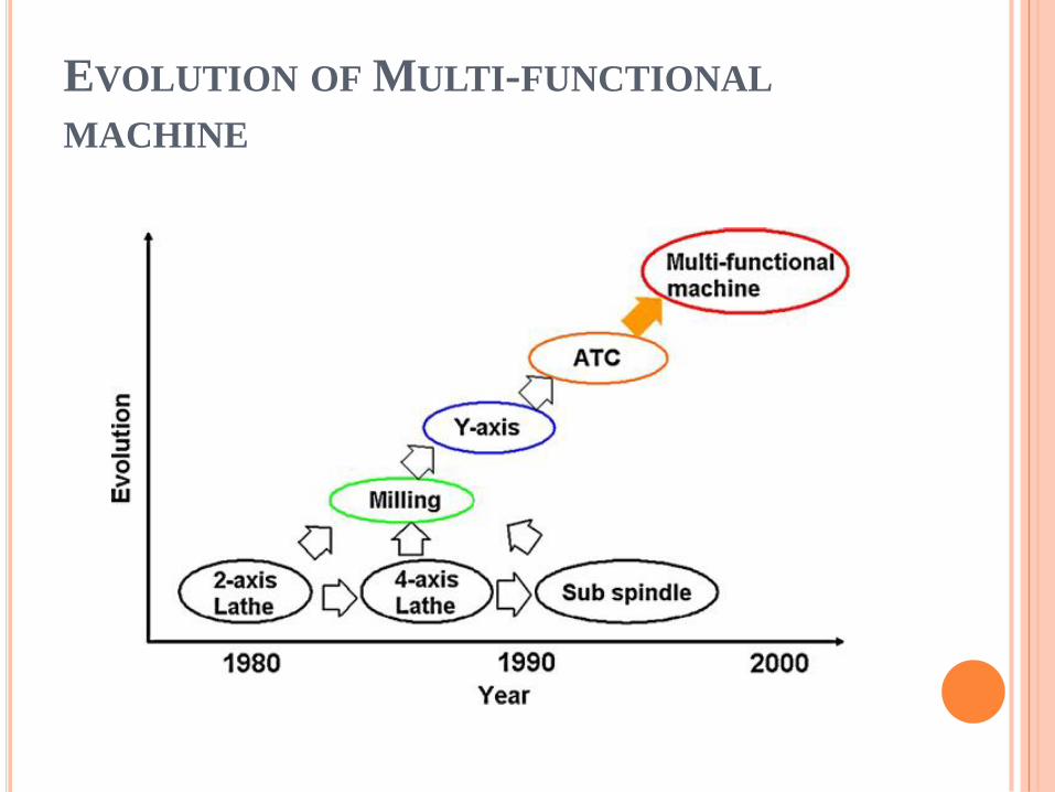
EVOLUTION OF MULTI-FUNCTIONAL
MACHINE

AN EXAMPLE OF AN EARLY TC DEVELOPED IN
1974
To offset the
relative
position of the
rotary axis of
work and the
tool position

SAMPLE CONFIGURATION OF RECENT MULTI-
FUNCTIONAL MACHINE TOOL.

EVOLUTION OF PARTS MACHINED BY TURNING
MACHINES.

2.2. MULTI-FUNCTIONAL MILLING
MACHINES
It was initially mainly used to machine flat surfaces &
later expanded to 2D and 3D surfaces.
The first NC (Numerical controlled) machine tool
developed by John T. Parsons in 1952 was a 3-axis
milling machine.
The first MC (Machining center) named Milwaukee-
Matic was developed by Kearney and Trecker in
1958.

MILWAUKEE-MATIC MODEL II DEVELOPED BY
KERNEY AND TRECKER IN 1958.

TYPICAL CONFIGURATION OF MC WITH ADDED
ROTARY AXES.

AN EXAMPLE OF SIMULTANEOUS MILLING AND
TURNING ON ONE MACHINE

3. DESIGN PRINCIPLE
Mathematical model of machine tool (Inasaki).

COORDINATE TRANSFORMATION MATRICES.

THREE POSSIBLE CONFIGURATIONS OF MACHINE
STRUCTURE.

POSSIBLE CONFIGURATIONS OF VERTICAL MC.

POSSIBLE COMBINATION OF MULTI-FUNCTIONAL
MACHINE
But the actual structure of the machine is determined by accuracy,rigidity,thermal deformation
property and ease of manufacturing.

4. EXAMPLES AND PRACTICAL APPLICATIONS
4.1. MULTI-FUNCTIONAL TURNING MACHINES
The aero space, automotive and other mechanical
industries as well as machining of dies and molds.
The turning machine based multi-functional machine
tools are mainly used to machine parts, with
complicated geometry, efficiently.

AN EXAMPLE OF HIGH PRODUCTIVITY, HIGH
FLEXIBILITY CNC TURNING CENTER.

AN EXAMPLE OF COMBINED MULTI-AXIS
MACHINE TOOL

FEASIBLE MACHINING OPERATIONS OF
COMBINED MULTI-AXIS MACHINE TOOL.

SPECIAL 9-AXIS CONTROL MILL/TURN LATHE
AND GAS TURBINE FUEL NOZZLE MACHINED.

HEAVY DUTY MULTI-PURPOSE 5-AXIS MILL/TURN
MACHINE

4.2. MULTI-FUNCTIONAL MILLING
MACHINES
The 5-axis MC is widely used to machine dies and molds.
5-axis control is not necessarily used in many cases, but a simultaneous 3-axes control cut with additional off-line 2-axis control for the work posture change is applied.
The prime advantage of this method is simplicity of the Programming.

ADVANTAGES OF 3 + 2 AXIS CONTROL
MACHINING.

COMPARISON BETWEEN 5-AXIS CONTROL AND 3
+ 2 AXIS CONTROL.

EXAMPLE OF 5-AXIS MC MACHINED PART
Machining of impeller
A machined compressor or turbine part
for jet engines made of titanium alloy.

5.KEY COMPONENTS AND SUPPORTING
TECHNOLOGIES
Feed drive
Rotary drive
High speed spindle
CAM software
Control technology
Cutting technology
NC program verification and collision avoidance

Feed drive :-
Rotary drive :-
High speed spindle :-
High speed machining centers are currently equipped with high speed spindles with maximum rotational speeds of 20,000–30,000 /min. Some specialmachine spindles have a maximum rotational speed up to100,000 /min.

CONTROL TECHNOLOGY
Virtual model of trajectory generation and axes control.
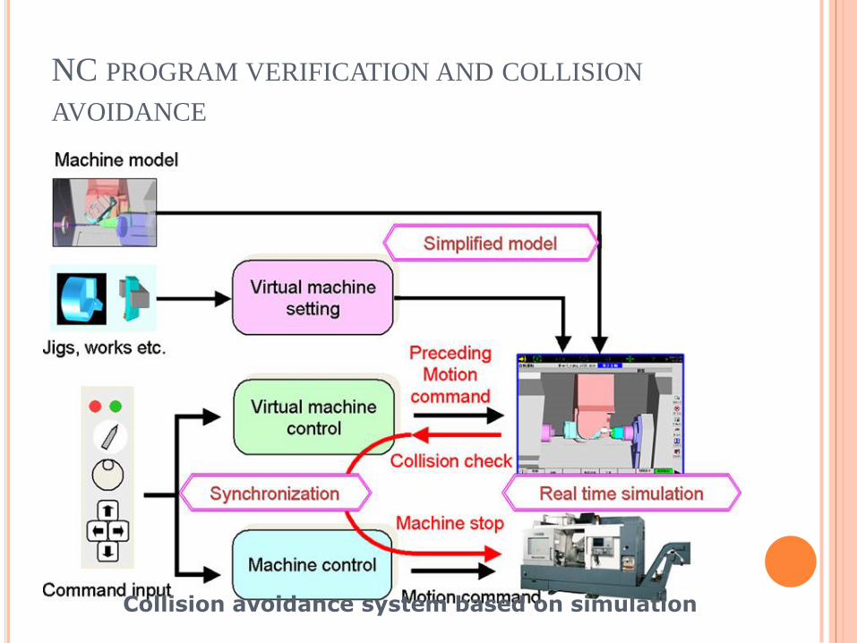
NC PROGRAM VERIFICATION AND COLLISION
AVOIDANCE
Collision avoidance system based on simulation

6.ASSESSMENT OF MULTI-FUNCTIONAL
MACHINE TOOLS
Evaluation of geometrical and motion accuracy:-
• In the past, the motion errors of individual axis, such as those of linear
motion or rotary motion were measured independently to evaluate the
accuracy of a machine tool.
• Now a well-known double-ball bar technique, proposed by Bryan,
has been widely applied to evaluate the motion accuracy of machine
tools. This technique calibrate parameter errors like backlash, positioning error, squareness,parallelism, etc.
Economical justification:-

7.CONCLUSIONS
Effort must be devoted to develop a scientific methodology to design new multi-functional machine tools as their demand is still increasing in order to machine complicated and difficult parts at higher speed with higher accuracy.
The control technology is the key issue to run the multifunctional machine tools effectively and accurately.
The virtual machine tool technology is expected to play an important role to support advancement of the collision free tool path and simultaneous control of multiple drives.
CAM software and the supporting technologies, such as NC programming and collision avoidance, are important from the practical point of view, and further efforts are needed to develop these technologies.
The technology to measure and evaluate the motion error of the multi-functional machine tools. As the number of axes of simultaneous control increases, it becomes extremely difficult to measure the motion error of the machine, especially when the linear and rotary motions are combined. Further research in this field is also needed.

8.REFERENCES
Altan T, Lilly B, Yen YC (2001) Manufacturing of Dies and Molds. Annals of theCIRP 50(2):405–423.
Altintas Y, Brecher C, Weck M, Witt S (2005) Virtual Machine Tool. Annals of the CIRP 54(2):651–704.
Boer CR, Petitti M, Lombardi F, Simon J-P (1990) A CAPP/CAM Expert Systemfor a High Productivity, High Flexibility CNC Turning Center. Annals of the CIRP 39(1):481–483.
Inasaki I (1994) Theory of Generation Motions for Machine Tools. Transactions of JSME Series C 60(574):1891–1895.
Inasaki I, Kishinami K, Sakamoto S, Takeuchi Y, Tanaka F (1997) Shape Generation Theory of Machine Tools. Yokendo Press.
Nakaminami M, Tokuma T, Moriwaki M, Nakamoto K (2007) Optimal Structure Design Methodology for Compound Multiaxis Machine Tools. I. Analysis of Requirements and Specifications. International Journal of Automation Technology1(2):78–86.
Saito A, Miyakawa M, Tsutsumi M (2001) Evaluation Method of Positional
and Geometric Deviations Using Simultaneous 4-axis Controlled Technique
in 5-axis Machining Center. Journal of JSPE 67(2):306–310.
Sato M (2006) Design and Performance of 5-axis Machines in Japan. Proceedingsof the 12th International Conference on Machine Tool Engineer’s, 167–189.
Woodbury RS (1972) Studies in the History of Machine Tools. MIT Press.