multi flowunit™ seal supply system - flow control oy...r3/8"(en 10226-2, tapered) or...
TRANSCRIPT
Multi FlowUnit™ Seal Supply System

_______________________________________________________________________________________________________________ © Flow Control Oy / EagleBurgmann, 2016 flowcontrol.fi eagleburgmann.com All rights reserved [email protected] [email protected]
1
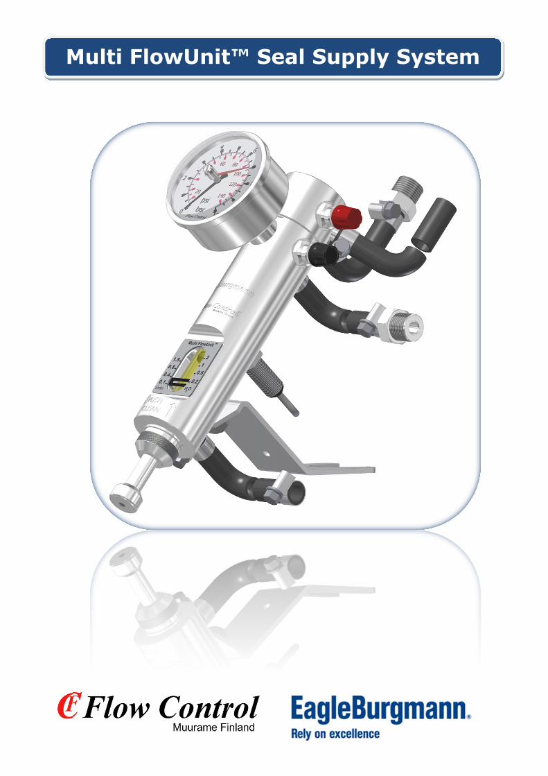
The Multi FlowUnit seal water control unit has been especially developed to monitor the amount of seal water used in mechanical dual seals in the pulp- and paper industries. A single Multi FlowUnit can take care of all flow adjustments and monitor for changes in the seal or the amount of seal water used. The Multi FlowUnit seal water control unit has two different functions in the same body: Zero-flow (Non-flow) for dual seals and a regular flush and pressure control. The Multi FlowUnit detects leakages in dual seals even under 0.1 liters (0,025 US gallons) into or out of the product. The inductive sensor connected to the Multi FlowUnit detects. Seal leakage could also be detected with other accessories, but a single Multi FlowUnit can do the job of several accessories and help keep maintenance costs lower. The Multi FlowUnit also incorporates an improved operating principle, which allows greater tolerances for impurities in the seal water. The unit can also operate as a standalone leakage sensor.
The Multi FlowUnit seal water control unit is also easy to modify for exceptional circumstances that demand chemical durability or hygienic properties from the materials. Examples include chemical, food- and mining industries and power plants.
Model MQ
Quench -seals, pressureless
Model MP
Packing- and single -seals
Model MD
Dual seals, pressurized
Multi FlowUnit™ Seal Supply System

_______________________________________________________________________________________________________________ © Flow Control Oy / EagleBurgmann, 2016 flowcontrol.fi eagleburgmann.com All rights reserved [email protected] [email protected]
2
Multi FlowUnit™ seal water control unit features and benefits The operating principle and flow meter reading Multi FlowUnit’s flow rate is indicated by a nearly frictionless U-shaped float, which together with the flow tube’s built-in circular aperture forms an accurate, stable and impurity-resistant volume flow. The technology is based on pressure differential and is of a varying aperture- type, but executed in a new way. The changes in the cross-sectional areas between the float and circular aperture together form the differential pressure, which is the same as the true flow rate. The flow rate can be seen on a scale on the meter’s body and a highly visible indicator on the float. Below is a cross-sectional image of the float and the particles it allows through. Advantages of the Non-Flow –functionality with dual-acting seals One of the most significant advantages of the Multi FlowUnit is that seal water flow can be reduced to almost nothing on Non-Flow seals. The maximum leakage flow in case of seal failure can be adjusted with the unit’s flow adjustment valve – into or out of the product. Removing air bubbles between the seal chamber and the system can be done with the unit’s pressure control unit or another simple valve solution, such as a ball valve. With the pressure control unit (also a vent valve) can and it is recommended to be used to flush the seal chamber.
Multi FlowUnit™ Seal Supply System
_______________________________________________________________________________________________________________ © Flow Control Oy / EagleBurgmann, 2016 flowcontrol.fi eagleburgmann.com All rights reserved [email protected] [email protected]
3
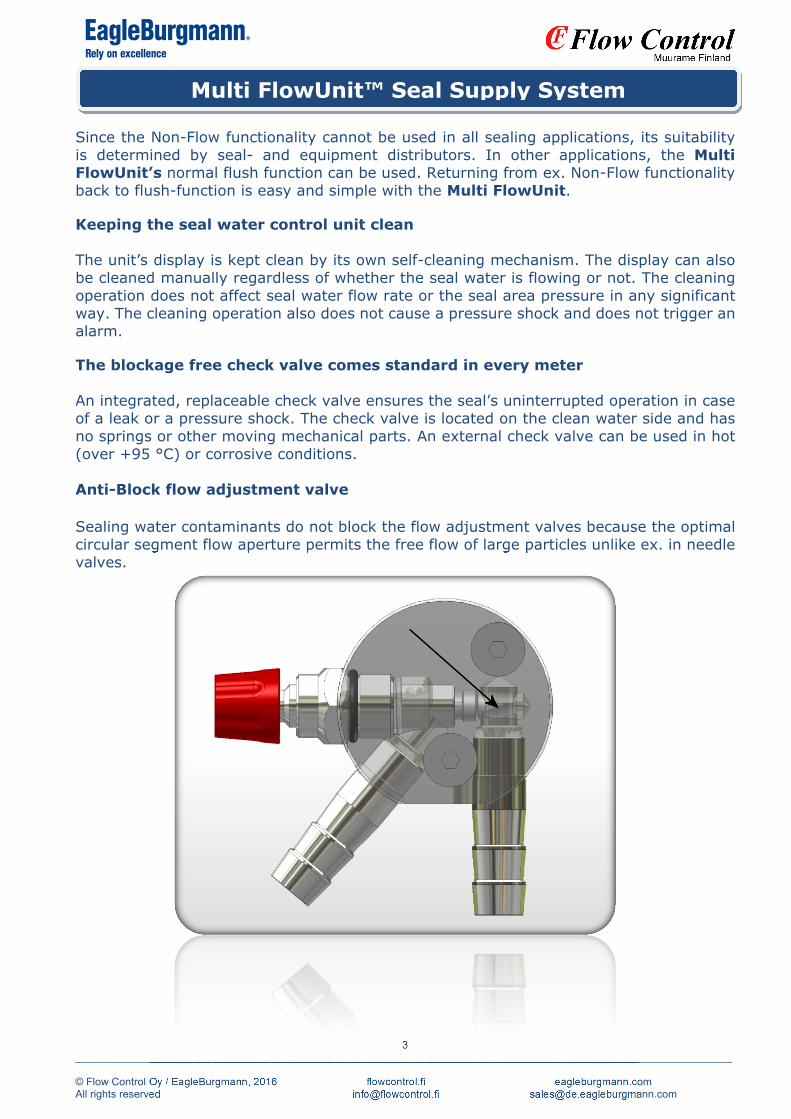
Since the Non-Flow functionality cannot be used in all sealing applications, its suitability is determined by seal- and equipment distributors. In other applications, the Multi FlowUnit’s normal flush function can be used. Returning from ex. Non-Flow functionality back to flush-function is easy and simple with the Multi FlowUnit. Keeping the seal water control unit clean The unit’s display is kept clean by its own self-cleaning mechanism. The display can also be cleaned manually regardless of whether the seal water is flowing or not. The cleaning operation does not affect seal water flow rate or the seal area pressure in any significant way. The cleaning operation also does not cause a pressure shock and does not trigger an alarm. The blockage free check valve comes standard in every meter An integrated, replaceable check valve ensures the seal’s uninterrupted operation in case of a leak or a pressure shock. The check valve is located on the clean water side and has no springs or other moving mechanical parts. An external check valve can be used in hot (over +95 °C) or corrosive conditions. Anti-Block flow adjustment valve Sealing water contaminants do not block the flow adjustment valves because the optimal circular segment flow aperture permits the free flow of large particles unlike ex. in needle valves.
Multi FlowUnit™ Seal Supply System

_______________________________________________________________________________________________________________ © Flow Control Oy / EagleBurgmann, 2016 flowcontrol.fi eagleburgmann.com All rights reserved [email protected] [email protected]
4
Seal damage A normal cause of damage to shaft seals is the dry running of mechanical shaft seals and the depletion of impregnated material in packing seals. In such circumstances both seal types suffer from a non-conforming seal water control unit or sometimes it can result in a complete deficiency. Packing seals Failure to ensure seal water in packing’s results in the burning of the seal, which causes depletion of impregnated material, ultimately resulting in overheating through friction. Such conditions result in packing’s hardening and an early end to their service life. Mechanical seals Failure to ensure seal water to mechanical shaft seals results in the overheating of moving surfaces, further resulting in surface damage. For this reason seals normally begin to leak and require either replacement or repair. The advantage of compression packing seals is that they can be tightened, as long as the preservative has not been lost. Both types of seals require clean sealing water in order to function reliably. Transferring sealing water to seals or other objects without a sealing water monitoring device is thus not recommended. Multi FlowUnit seal water control unit prevents dry running of shaft seal solutions and at the same time cools, if required, the seal area. In addition the unit maintains a manageable amount of flow leakage preventing material wear from blocking the seal area. The Multi FlowUnit also assists in optimizing the amount of seal water usage. At the same time it reduces wastewater loads and enables seal solutions to operate reliably, with a longer service life and reduced maintenance costs.
Technical data Flow ranges: 0.1-2, 0.5-4 and 1-8 LPM / 0.025-0.5, 0.13-1 and 0.25-2 USGPM Max. pressure: 25 bar / 360 psi (pressure ranges 0-10/16/25 bar, 0-145/230/360 psi Max. temperature:
+85°C / +185°F (POM-body) (for non-corrosive conditions) +120°C / +248°F (Stainless steel body with a PSU flow tube)
Typical accuracy: ±3-5 % (o. F.S.)
Pressure loss: 0.1 bar @ 4 LPM, ≥ 1 bar @ 8 LPM / 1.5 psi @ 1 USGPM, ≥ 15 psi @ 2
USGPM Body material type: Stainless steel EN 1.4305/AISI304 or POM-C (PVDF) Metal parts: Stainless steel EN 1.4305/AISI304 (1.4401/-04/AISI316/-L) Flow tube: Grilamid TR 55 (PSU or glass) Seals: NBR (FPM) Supports: Stand, Z- or L- brackets
Multi FlowUnit™ Seal Supply System

_______________________________________________________________________________________________________________ © Flow Control Oy / EagleBurgmann, 2016 flowcontrol.fi eagleburgmann.com All rights reserved [email protected] [email protected]
5
Easy to read scale
A new principle of operation - improved accuracy Reduced flow range from
0.1 to 2 LPM (0.025 - 0.5 USGPM) Allows greater tolerances for impurities in seal water
Set value indicators for flow and pressure monitoring
Built-in flow tube cleaner – spring loaded Anti-clog circular-aperture control valves
Anti-clog non-return valve as standard in every supply system (flowmeter)
Also available with pressure transmitter and other additional indicators
The device can also function as a standalone leakage sensor
without a control valve or a pressure gauge Stainless steel available as a material option Low limit alarm warns of low flow rates or
seal leaks IN or OUT Available with inductive switches of various
outputs and voltages Delivered as a ready for installation- package Installation, maintenance and repair services
Multi FlowUnit™ Seal Supply System
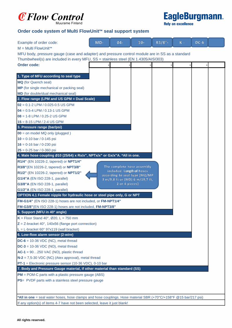
Order code system of Multi FlowUnit™ seal support system
Example of order code:
M = Multi FlowUnit™
MFU body, pressure gauge (case and adapter) and pressure control module are in SS as a standardThumbwheel(s) are included in every MFU, SS = stainless steel (EN 1.4305/AISI303)
Order code: - - - - - -
1. Type of MFU according to seal type
MQ (for Quench seal)
MP (for single mechanical or packing seal)
MD (for double/dual mechanical seal)
2. Flow range (LPM and US GPM = Dual Scale)
02 = 0.1-2 LPM / 0.025-0.5 US GPM
04 = 0.5-4 LPM / 0.13-1 US GPM
08 = 1-8 LPM / 0.25-2 US GPM
15 = 8-15 LPM / 2-4 US GPM
3. Pressure range (bar/psi)
00 = on model MQ only (plugged )
10 = 0-10 bar / 0-145 psi
16 = 0-16 bar / 0-230 psi
25 = 0-25 bar / 0-360 psi
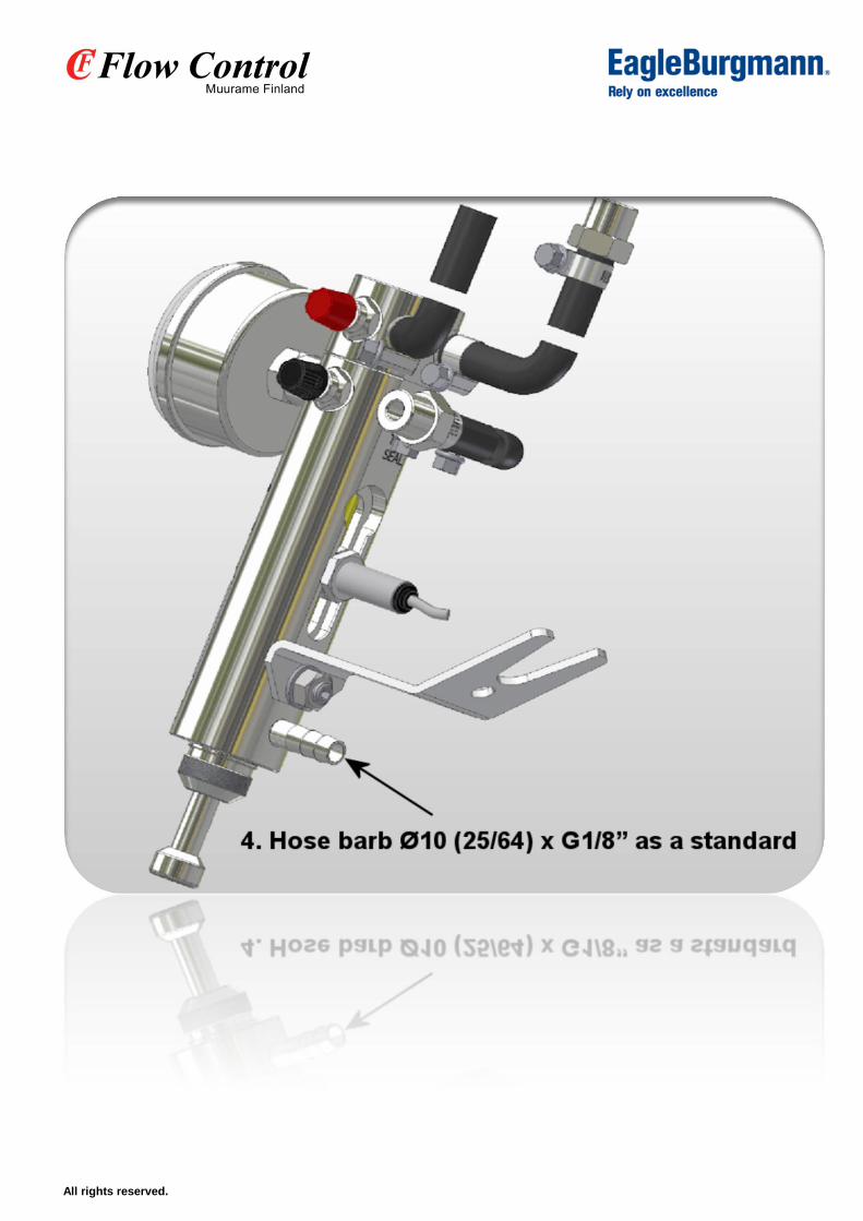
4. Male hose coupling Ø10 (25/64) x Rx/x", NPTx/x" or Gx/x"A. *All in one.
R1/4" (EN 10226-2, tapered) or NPT1/4"
R3/8"(EN 10226-2, tapered) or NPT3/8"
R1/2" (EN 10226-2, tapered) or NPT1/2"
G1/4"A (EN ISO 228-1, parallel)
G3/8"A (EN ISO 228-1, parallel)
G1/2"A (EN ISO 228-1, parallel)
OPTION 4.1 Female nipple for hydraulic hose or steel pipe only, G or NPT
FM-G1/4" (EN ISO 228-1) hoses are not included, or FM-NPT1/4"
FM-G3/8"(EN ISO 228-1) hoses are not included, FM-NPT3/8"
5. Support (MFU in 40° angle)
K = Floor Stand 40°, Ø20, L = 750 mm
Z = Z-bracket 40°, 140x56 (flange port connection)
L = L-bracket 60° 97x119 (wall bracket)
6. Low-flow alarm sensor (2-wire)
DC-6 = 10-36 VDC (NC), metal thread
DC-3 = 10-36 VDC (NO), metal thread
AC-1 = 90…250 VAC (NO), plastic thread
N-2 = 7,5-30 VDC (NC) (Atex approval), metal thread
PT-1 = Electronic pressure sensor (10-36 VDC), 0-10 bar
7. Body and Pressure Gauge material, if other material than standard (SS)
PM = POM-C parts with a plastic pressure gauge (ABS)
PS= PVDF parts with a stainless steel pressure gauge
*All in one = seal water hoses, hose clamps and hose couplings. Hose material SBR (+70°C/+158°F @15 bar/217 psi)
If any option(s) of items 4-7 have not been selected, leave it just blank!
ength of
All rights reserved.
All rights reserved.