multi-diameter, bi-directional pigging for pipeline … · multi-diameter, bi-directional pigging...
TRANSCRIPT

MULTI-DIAMETER, BI-DIRECTIONAL PIGGING FOR PIPELINE PRE-
COMMISSIONING Magne Andreas Vik, StatoilHydro; Alf Åge Kristiansen, StatoilHydro; Simon Sykes, FTL Seals Technology; Steve Hutcheson, Pipeline Pigging Technology and Aidan O’Donoghue, Pipeline Research Limited.
This paper examines the issues associated with multi-diameter, bi-directional pigging specifically for pipeline pre-commissioning. The technique can be used to flood and subsequently dewater a pipeline without the need for temporary subsea traps. An example is the Alve Pipeline in Norway. This 16 km flow-line from the Norne Platform to the Alve Manifold includes 10” and 12” pipe sections. The line was flooded from Norne using the pig with oxygen scavenged seawater and then dewatered using Nitrogen and produced gas from the well. The pigs needed to have a high sealing efficiency since very low velocities were used to flood the line and in order to avoid hydrates on dewatering. Multi-diameter wheel pigs were employed with non-buckling disc type seals. This paper describes the design of the pigs and the seals to achieve the required functionality. The test facility and testing performed to verify the pig performance is also illustrated. Finally, an overview of the offshore pigging operation is provided.
Introduction In order to flood and subsequently dewater the Alve flow line, a number of high seal, multi-diameter and bi-directional pigs were required. The pipeline contains several internal diameters from 10” to 12”. Since no pigging from the Alve manifold was possible (no launcher), all operations needed to be performed from Norne FPSO.
Four pigs spaced with MEG were launched from Norne with oxygen scavenged water, propelled through the pipeline and then stopped in position just upstream of the manifold. Before start-up of the pipeline and introduction of hydrocarbon gas, the pigs were required to be reversed with nitrogen and travel back through the pipeline, with no gas bypass, and be received back on Norne. Pressure was first raised to 50 bar with nitrogen for pigging and to 80 bar with hydrocarbons from topside to give back pressure for start up. A field schematic is shown in Figure 1.
Initially it was considered to perform this operation without any pigs – but after a number of studies, the hydrate risk was considered to be too great. The need for high seal pigs was identified. A number of additional scenarios for the operation were considered which impacted on pig design: -
1. Reversal of the pigs from the manifold, just before the inline isolation valve – the risk is that the pig will travel too far and will not be reversible from the 5” inlet line (Pumping into the middle of the pig rather than upstream);
2. Reversal of the pigs from before the expansion spool. The implication is that the pig does not need to operate negotiate any bends in the large diameter line.
The base case was the second option, but consideration needed to be given to the first option as a potential contingency. Testing would be performed to establish pig efficiency in all components including the 12” bends and to establish if the first pig in the train was reversible from the valve location. If this proved to be difficult then additional procedural steps would be taken to avoid the train reaching the manifold.

A pig train consisting of four pigs with MEG separation was required. The main pipeline features were as follows: -
• 10” Vertical launcher; • 10” topside piping at launcher, 257mm internal diameter; • 10” topside and riser, 267mm internal diameter; • 12” pipeline, 320mm internal diameter, 15.7 km in length; • 12” tie in spools and manifold, 305mm internal diameter with 5D bends.
The following Functional Requirements were discussed and agreed with the project: -
• The pigs must be fully bi-directional with high sealing ability in both directions; • Low flow rates were expected, in the region of 300-400 l/min resulting in a pig
velocity of 0.03 m/s to 0.08 m/s. The pig must be able to operate at such low velocities;
• Good seal efficiency and pig support/centralisation were required to ensure safe negotiation with minimum bypass through all components along the system. The risk of gas bypassing on return to Norne could result in hydrate formation;
• Ratio between pig flip differential pressure (pressure to flip the seals forward and cause them to fail) and running differential pressure to be at least 5:1;
• The drive differential pressure in all pipeline components was requested to be less than 7 bars;
• Pigs to be fitted with isotope holder for tracking purposes; • Pig handling to be considered for vertical launch and receipt.
The final aspect that needed to be considered as a contingency was the possibility of the pig travelling too far into the manifold and provision of a method of reversal from this location. This may mean that the pig straddled the manifold inlet used for driving the pig back to Norne.
Pig Selection The timescales for the project were relatively short with initial feasibility in August 2008 and required pig delivery in December 2008. This only allowed three months to establish concepts, perform detailed engineering, test to verify the pig functionality and provide four units for the operation.
An initial feasibility study was undertaken with the aim of selecting a single pig type for development for this application. Several different types of multi-diameter pigs were considered for this duty: -
1. Traditional multi-diameter pig with slotted guides and various diameter seals; 2. Wheel pig or VaripigTM from FTL Seals Technology; 3. Paddle Pig from Pipeline Engineering; 4. Other approaches from other suppliers.
It must be stressed that whilst multi-diameter pigs have been successfully developed and used on many occasions, the project was not aware of any projects which have developed a multi-diameter bi-directional pig and with such a high emphasis on sealing (i.e. no visible leakage in any pipeline component). The pros and cons of each technology was discussed and it was concluded that given the timescales, then the wheel pig would be the best choice with the highest possibility of success. On the other hand, it is noted that with more time, the other methods could also be made to work.
No other pig was considered for this project from this point onwards. It is considered the best approach to concentrate all efforts on one chosen approach with a high probability of success rather than to dilute the effort by having several different competing pig prototypes which have lower chance of success and take up excessive testing time. Running a

competition for pig development is considered inefficient in general and it is better to establish the base case in a feasibility phase and then develop this further.
Pig Design The pig mechanical design was performed by FTL Seals Technology with input and guidance from Pipeline Pigging Technology and Pipeline Research Limited. In addition, StatoilHydro ensured that the requirements from the project were communicated as soon as possible. This is especially important in a tight timescale project and where small changes to the operation philosophy can have significant implications on the pig design. This was managed effectively throughout the development.
The outline concept pig design is shown in Figure 2. The pig consists of two wheel modules with interlinked suspension arms. The pig travels on the centreline of the pipe and so it is easier to specify seals that will provide a good sealing action. The spring force in the suspension units is greater than the weight of the pig and so if the pig drops below centreline, then the restoring force is greater. The geometry of the wheel arms provides a mechanical advantage which results in a flat force / deflection curve, i.e. the force require to deflect the arms does not increase significantly in smaller diameters. As a result, the load on the wheels and bearings remains at an acceptable and determinable level.
For the Alve pig, these wheel units are facing each other with seals at either end. The pig is axi-symmetrical in design which guarantees full bi-directionality, See Figure 3. It was decided early on that a single, non-buckling seal would be used for both line sizes (10” and 12”). This is discussed in detail below.
Detailed engineering on this concept followed and it became clear that in the event that the pig needed to travel through the 5D bends at the manifold, then there could be leakage past the pig. This is demonstrated in Figure 4. This is not acceptable for these Functional Requirements.
To solve the problem an additional seal was introduced in the centre of the pig – see Figure 5. Other issues associated with the layout of the pig include: -
1. Installation of an isotope holder. This is shown in Figure 6; 2. Provision of a lifting bar at the rear of the pig, see also Figure 6 – the pig is loaded
and removed from Norne as it is not handled subsea; 3. The front pig in the train was also a special, known as Type 1 Pig – as this pig could
potentially end up in the manifold and come to rest near the ball valve at the end of the manifold straddling the inlet line. This then required a slightly longer bumper nose to ensure that a seal was always downstream of the manifold off-take. The reversal of the pig from the manifold in the event of over-travel was subject to additional testing and modification as described later in this paper.
Seal Design The design of the seals for this pig was critical. One advantage of the wheel pig is that it supports the pig on the pipe centreline. The result is that, the seal diameter can be set just greater than the internal diameter of the largest bore and still provide a very good wiping action. Coupled with this, there has been good success lately with using a single disc seal to span several line sizes without buckling in the smallest size. This is known as the Single Seal concept.
The idea is that a single oversized disc has the ability to work and provide a good seal at a range of smaller and smaller diameters before it finally buckles. The following scale of “buckling” has been investigated previously: -
1. No buckle; 2. Buckles when forced but recovers; 3. Buckles when forced but does not recover; 4. Buckles even when not forced to do so.

To be safe, for this application, it is important that the seal does not buckle or if forced to do so, it returns to a full seal. Over the years much experience has been gained on buckling and non-buckling of seals for dual and multi-diameter pigging. Figure 7 shows some examples of where the large diameter seals are intentionally buckled into the small diameter line in order to allow smaller diameter seals to take over. This has been used to good effect in large diameter change projects where Buckle Inducers are used to force the seal to fold into the small diameter line.
The opposite is now proposed – using seals that do not buckle when they enter the small diameter line. The advantage of using such a seal in this development is that a single seal can be used at the front and the rear of the pig. As a result there is no interference between small diameter and large diameter seals over a limited pig length.
A routine has been developed to establish if a seal will buckle or not. Four criteria must be met to ensure that the seal will behave in the required way at different line sizes. This is based on a buckle model of the seal coupled with test and field data. The output is shown in Figure 8 for this development. Based on this analysis, a number of seal sizes were selected both for the main seals either end of the pig and also for the central seal positioned to avoid leakage in the 12” bends. A base case pig was also established for initial use in testing. The aim is always to arrive on the test site with a base case design and a number of spares and alternatives to help solve any problems with the pig during verification testing.
Testing The tests were performed at K-Lab at Kårstø in Norway. The test facility is shown in Figure 9. The facility consisted of the main components in the Alve flow-line: -
• Launcher (Horizontal for test purposes); • Tight 10” section at the beginning, 257 mm ID; • 10” Topside and riser piping, 267 mm ID; • 10” x 12” Transition; • 12” spool with 12” equal tee, 307mm ID; • 12” pipeline, 323 mm ID (320 mm ID test pipe unavailable); • 12” manifold pipe, 305 mm ID; • 12” bend, 305 mm ID.
A manifold spool with 2 off 6” tees was also included for reversal tests.
All testing was performed open ended to allow the pigging to be observed. This is for assurance that the pig is not visibly leaking and that the seal is adequate and fit for purpose. Testing in a closed loop hides many problems and only demonstrates that the pig travels from launch to receipt – it does not establish that it travels reliably from launch to receipt. Proper risk assessment, procedures and testing with water drive ensures that the HSE risk is minimal.
Launcher inlet pressure, flow-rate and pig location using magnetic signallers were recorded during all tests. The following set of tests was performed: -
TEST DESCRIPTION PARAMETERS 1 Full Facility Test
Test pig through the full test facility. Measure pig velocity over length of test rig, running pressure and flow rate. Observe leakage past the pig.
2 Reverse in Full FacilityReverse the pig through the full test facility.
Measure pig velocity over length of test rig, running pressure, reverse pressure and flow rate. Observe leakage past the pig.
3 Initial Spools TestLaunch 257.3mm � 266.7mm � 305mm straight and flip.
Measure running pressure, flow rate and flip pressure. Observe leakage past the pig.
4 Observation of rear of pig Stop the pig in the 266.7 mm section,
TEST DESCRIPTION PARAMETERS Stop pig in 266.7mm section and observe rear of pig for buckling.
remove trap, observe rear of pig, try to induce buckle in seal.
5 Main pipeline TestLaunch 257.3mm � 266.7mm � 305mm � 320mm straight and flip. Repeat at very low and low flows.
Measure running pressure, flow rate and flip pressure. Observe leakage past the pig.
6 Pig to 305mm section Launch 257.3mm � 266.7mm � 305mm � 320mm �305mm straight.
Measure running pressure and flow rate. Observe leakage past the pig.
7 Bend TestLaunch 257.3mm� 266.7mm � 305mm � 320mm �305mm � 305mm bend
Measure minimum flow in bend before pig stall. Observe leakage past the pig.
8 Bend Test flipLaunch 257.3mm� 266.7mm � 305mm � 320mm �305mm � 305mm bend and flip.
Measure running pressure, flow rate and flip pressure. Observe leakage past the pig.
9 Manifold Test 1Launch 257.3mm� 266.7mm � 305mm � 320mm �305mm � 305mm bend � Into manifold and dead head.
Measure running pressure, manifold pressure and flow rate. Record position of pig in Manifold. Reverse pig slowly from Manifold. Observe leakage past pig on reverse.
10 Manifold Test 2 Launch 257.3mm� 266.7mm � 305mm � 320mm �305mm � 305mm bend� Into manifold and stop at second off-take.
Measure running pressure and flow rate. Record position of pig in Manifold. Reverse pig slowly from Manifold. Observe leakage past pig on reverse.
11 Permanent Set Test 1Leave pig in 257.3mm spool over night (12 hours minimum). Launch � 266.7mm � 305mm � 320mm straight.
Measure running pressure and flow rate. Observe leakage past the pig.
12 Permanent Set Test 2Leave pig in 266.7mm spool over night (12 hours minimum). Launch � 266.7mm � 305mm � 320mm straight.
Measure running pressure and flow rate. Observe leakage past the pig.
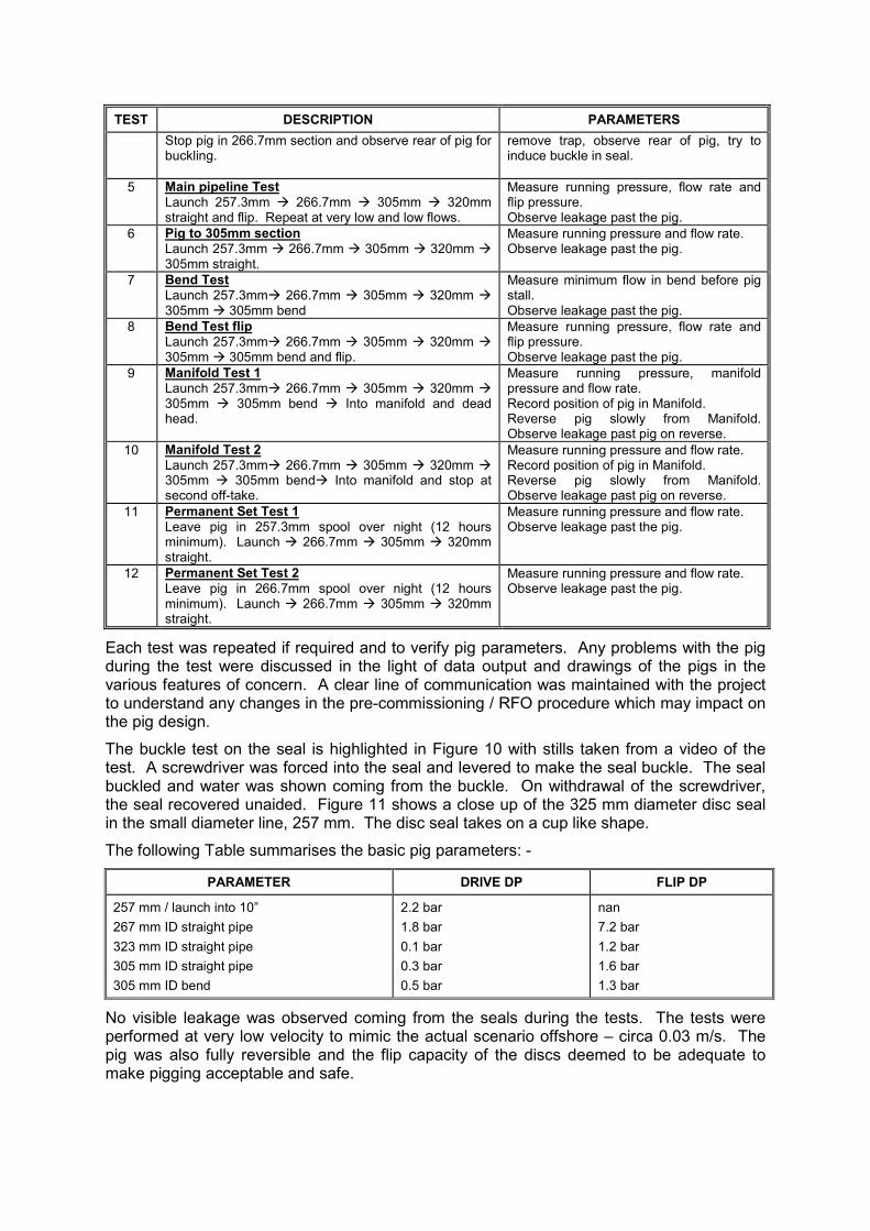
Each test was repeated if required and to verify pig parameters. Any problems with the pig during the test were discussed in the light of data output and drawings of the pigs in the various features of concern. A clear line of communication was maintained with the project to understand any changes in the pre-commissioning / RFO procedure which may impact on the pig design.
The buckle test on the seal is highlighted in Figure 10 with stills taken from a video of the test. A screwdriver was forced into the seal and levered to make the seal buckle. The seal buckled and water was shown coming from the buckle. On withdrawal of the screwdriver, the seal recovered unaided. Figure 11 shows a close up of the 325 mm diameter disc seal in the small diameter line, 257 mm. The disc seal takes on a cup like shape.
The following Table summarises the basic pig parameters: -
PARAMETER DRIVE DP FLIP DP
257 mm / launch into 10” 267 mm ID straight pipe 323 mm ID straight pipe 305 mm ID straight pipe 305 mm ID bend
2.2 bar 1.8 bar 0.1 bar 0.3 bar 0.5 bar
nan 7.2 bar 1.2 bar 1.6 bar 1.3 bar
No visible leakage was observed coming from the seals during the tests. The tests were performed at very low velocity to mimic the actual scenario offshore – circa 0.03 m/s. The pig was also fully reversible and the flip capacity of the discs deemed to be adequate to make pigging acceptable and safe.

The final test performed was to see if the pig would reverse when positioned against the manifold ball valve. The position meant that the pig would straddle the inlet as shown in Figure 12. To allow the pig to reverse from this position, bypass ports were opened in front of this pig. This would allow pressure to be transferred from between the pig seals to the ball valve to allow the pig to move backwards (net force on the pig pushing it in reverse). The size of the ports is critical as the flow needed to generate the necessary reversal pressure must be able to pass through these ports. It was anticipated that this would prove to be difficult given the limitations on bypass size and also on available flow into the off-take.
The problem is outlined in Figure 13 in a story board. There is a trade off between the ability to get the flow through the bypass ports to displace the pig and the ability of the rear seal to hold this pressure without leakage. This has been achieved in other projects but on those occasions the balance was easier to achieve. Sleeper discs were used to attempt to increase the pressure capacity of the rear seal but this was ineffective. The final position, where some degree of reversal was possible at the ball valve / straddling the off-take, was where the rear two seals were upstream of this off-take (Figure 14). This could not be guaranteed as the front of the pig would have to be extended resulting in an unwieldy design and problems negotiating the bends. As a result, the emphasis was put back on the operation to avoid the pig reaching this position in the first place. This was insured by increasing the tracking effort subsea.
Offshore Operation The operation took place in March 2009. The operation was a success and the pigs performed well and no gas bypass observed.
Four pigs were launched from a temporary vertical pig launcher at Norne topside. Before the first pig entered the expansion spool at the manifold, the pig train was planned to be stopped. Due to a delay in communication and the short distance from detection to spool, the first pig finally stopped inside the spool having passed the first 5D bend.
After all the pigs had been located using isotope tracking, the pig train was reversed and discs flipped with MEG before returned with nitrogen.
For both outbound flooding with water and return pigging with nitrogen, the pressure experienced were consistent with the pigging trials performed.
Conclusion The multi-diameter bi-directional approach to pre-commissioning RFO (Ready for Operation) is being looked in more detail as it potentially rules out the need for a subsea receiver or launcher and an extra support vessel. The ability to make a single disc seal work over a wide range of diameters is key to this development as is the wheel pig to allow the pig to be maintained on the centreline. The Alve pipeline was approximately 25% increase in diameter. StatoilHydro is now examining a 12” x 16” case with a 41% change in diameter where a similar approach is being adopted with further work on the single seal concept being examined.
We would like to thank Olaf Erland and Tor Grindheim at K-Lab in Kårstø for their assistance in this development.

Figure 1, Field Schematic
Figure 2, Initial Pig Concept

Figure 3, Initial Axi-symmetrical Design
Figure 4, Possible Leakage at the bends
View showing limited interference between the seals and the inside of the bends. There is therefore a risk of leakage.

Figure 5, Additional Seal at centre of the pig to avoid leakage at bends
Figure 6, Isotope holder and towing arm
Tow bar
Non-buckled flat disc
Isotope holder

Figure 7, Examples of Buckled Seals
Three buckle Inducers used on SVAN project. Buckle Inducers are used to force the seals to buckle.
Four buckle Inducers used on Norne Heidrun project.
View on large diameter seal which has been allowed to buckle naturally into the small diameter line. This leads to high friction and damage to the seal.

Figure 8, Seal sizing for buckling or Non-buckling
The green area shows the area where non-buckling can be expected for given seal thickness and flange diameter. The grey area is where buckling may occur. The red area is where buckling will most definitely occur.
Figure 9, Test Facility
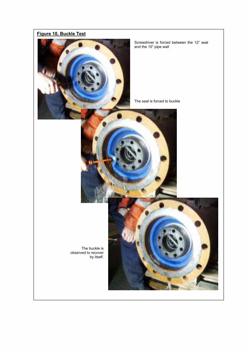
Figure 10, Buckle Test
Screwdriver is forced between the 12” seal and the 10” pipe wall
The seal is forced to buckle
The buckle is observed to recover
by itself.

Figure 11, Flat disc seal in small diameter
Flat 325 mm sealing disc outside the pipe.
Same disc in 257 mm pipe takes on a cup shape but does
not buckle
Figure 12, Reversal Position at Valve

Figure 12, Reversal at the ball valve – story board

Figure 15, Final Pig Design
Figure 14, Reversal Position at Valve