multi-contact pv-us01 catalog - ec.staubli.comec.staubli.com/tools/certification/pdf/us01n.pdf ·...
TRANSCRIPT

MC® “Plug-n-Play” Connector Systemfor Photovoltaic Applications
600 V DC 20A - 30AUL File # E181720
For timesaving, safe andreliable cabling ofPV-Modules
Installation Instructions- For U.S. Distribution Only -
UL Recognized Connectors and Junction Boxes
Multi-Contact USA5560 Skylane Blvd.
Santa Rosa, CA 95403
PV-US01
Multi-Contact USAMulti-Contact USAMulti-Contact USAMulti-Contact USAMulti-Contact USA- Advanced Contact Technology -

- 1 -
1) Cable outer diameter 2) Cable cross section 3) With assembly device PV-RWZ, up to 8mm dia.; pre-assembled cable up to 9mm dia.
The following assembly instructions are designed to assist in the proper installation of the Multi-Contact® “Plug-n-Play” photovoltaic connector system. When proper installation procedures areused, the “Plug-n-Play” system produces timesaving, dependable cabling of solar modules for bothfreestanding and structurally integrated systems.
Before beginning the assembly process, it is critical that you double check to make sure that you areusing the proper selection of hardware not only for your application, but for the correct assemblycombination of connector, insulator, and cabling as well. Each connector and insulator in the “Plug-n-Play” series has a range of both conductor diameter (di) and insulator outer diameter (D) associ-ated with it. Please refer to the following tables to ensure you have the proper combination:
diPin Insulator Pin dia. 3 mm dia. mm
PV-T3I/S UR 32.0701UR PV-SP3/4 32.0500 3
PV-T3II/S UR 32.0703UR PV-SP3/4 32.0500 3
PV-T3III/S UR 32.0705UR PV-SP3/4 32.0500 3
PV-T3III/S UR 32.0705UR PV-SP3/6 32.0502 4
Parts list
A B D1) D2)
Type Order No dia. mm mm dia. mm mm2
PV-KST3I UR 32.0001UR 13.5 41.6 3.2-4.8 2-4
PV-KST3II UR 32.0003UR 13.5 41.6 4.9-7.1 2-4
PV-KST3III UR 32.0005UR 13.5 51.6 6.5-93) 2-4
PV-KST3/6III UR 32.0007UR 13.5 51.6 6.5-93) 6
PV-KST3I URPV-KST3II URPV-KST3III URPV-KST3/6III UR
Male Cable Connector Series I, II, III, & 6III
diSocket Insulator Socket dia. 3 mm dia. mm
PV-T3I/B UR 32.0700UR PV-BP3/4 32.0100 3
PV-T3II/B UR 32.0702UR PV-BP3/4 32.0100 3
PV-T3III/B UR 32.0704UR PV-BP3/4 32.0100 3
PV-T3III/B UR 32.0704UR PV-BP3/6 32.0101 4
Parts list
A B D1) D2)
Type Order No dia. mm mm dia. mm mm2
PV-KBT3I UR 32.0000UR 13.5 40 3.2-4.8 2-4
PV-KBT3II UR 32.0002UR 13.5 40 4.9-7.1 2-4
PV-KBT3III UR 32.0004UR 13.5 50 6.5-93) 2-4
PV-KBT3/6III UR 32.0006UR 13.5 50 6.5-93) 6
PV-KBT3I URPV-KBT3II URPV-KBT3III URPV-KBT3/6III UR
Female Cable Connector Series I, II, III, & 6III
Multi-Contact USAMC® Connector system for Photovoltaics
600 V DC • UL Recognized • 20A - 30A
- 2 -
*IMPORTANT*Only UL recognized SE, US, or USE cabling can result in a UL recognized cable assembly. It isimportant to verify that the cabling purchased for use with the “Plug-n-Play” system meet thesestandards prior to creating any wiring assemblies. Multi-Contact recommends using USE-2 andRWH-2 wire for most photovoltaic applications.
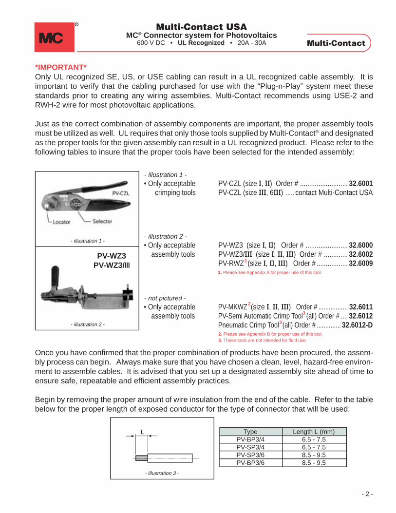
Just as the correct combination of assembly components are important, the proper assembly toolsmust be utilized as well. UL requires that only those tools supplied by Multi-Contact® and designatedas the proper tools for the given assembly can result in a UL recognized product. Please refer to thefollowing tables to insure that the proper tools have been selected for the intended assembly:
Once you have confirmed that the proper combination of products have been procured, the assem-bly process can begin. Always make sure that you have chosen a clean, level, hazard-free environ-ment to assemble cables. It is advised that you set up a designated assembly site ahead of time toensure safe, repeatable and efficient assembly practices.
Begin by removing the proper amount of wire insulation from the end of the cable. Refer to the tablebelow for the proper length of exposed conductor for the type of connector that will be used:
- illustration 3 -
L
- illustration 1 -
PV-WZ3PV-WZ3/III
- illustration 2 -
- illustration 1 -• Only acceptable PV-CZL (size I, II) Order # .......................... 32.6001 crimping tools PV-CZL (size III, 6III) ..... contact Multi-Contact USA
- illustration 2 -• Only acceptable PV-WZ3 (size I, II) Order # ....................... 32.6000 assembly tools PV-WZ3/III (size I, II, III) Order # ............. 32.6002
PV-RWZ (size I, II, III) Order # ................. 32.6009
- not pictured -• Only acceptable PV-MKWZ (size I, II, III) Order # ................. 32.6011 assembly tools PV-Semi Automatic Crimp Tool (all) Order # .... 32.6012
Pneumatic Crimp Tool (all) Order # .............. 32.6012-D
TypePV-BP3/4PV-SP3/4PV-SP3/6PV-BP3/6
Length L (mm)6.5 - 7.56.5 - 7.58.5 - 9.58.5 - 9.5
1
2
1. Please see Appendix A for proper use of this tool.
2. Please see Appendix B for proper use of this tool.
3
3
3. These tools are not intended for field use.
Multi-Contact USAMC® Connector system for Photovoltaics
600 V DC • UL Recognized • 20A - 30A
- 3 -
Note: “Plug-n-Play” insulators are actually positioned over the connector and wire terminationAFTER the connector is affixed, and is pressed on from the front of the connector. This is oppositeof the standard method of sliding the insulator onto the wire prior to affixing the connector. DO NOTslide the insulator on to the wire prior to crimping the connector.
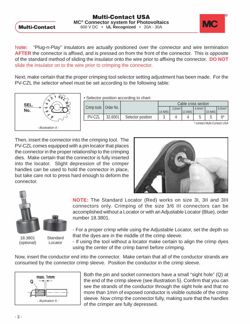
Next, make certain that the proper crimping tool selector setting adjustment has been made. For thePV-CZL the selector wheel must be set according to the following table:
• Selector position according to chart:
3 4 4 5 5 6*
Cable cross sectionCrimp tools Order No. 2.5mm2
14 AWG 12 AWG 10 AWG
PV-CZL 32.6001 Selector position
4.0mm2 6.0mm2
* contact Multi-Contact USA
Then, insert the connector into the crimping tool. ThePV-CZL comes equipped with a pin locator that placesthe connector in the proper relationship to the crimpingdies. Make certain that the connector is fully insertedinto the locator. Slight depression of the crimperhandles can be used to hold the connector in place,but take care not to press hard enough to deform theconnector.
- illustration 4 -
Now, insert the conductor end into the connector. Make certain that all of the conductor strands areconsumed by the connector crimp sleeve. Position the conductor in the crimp sleeve.
Both the pin and socket connectors have a small “sight hole” (Q) atthe end of the crimp sleeve (see illustration 5). Confirm that you cansee the strands of the conductor through the sight hole and that nomore than 1mm of exposed conductor is visible outside of the crimpsleeve. Now crimp the connector fully, making sure that the handlesof the crimper are fully depressed.
- illustration 5 -
Multi-Contact USAMC® Connector system for Photovoltaics
600 V DC • UL Recognized • 20A - 30A
NOTE: The Standard Locator (Red) works on size 3I, 3II and 3IIIconnectors only. Crimping of the size 3/6 III connectors can beaccomplished without a Locator or with an Adjustable Locator (Blue), ordernumber 18.3801.
- For a proper crimp while using the Adjustable Locator, set the depth sothat the dyes are in the middle of the crimp sleeve.- If using the tool without a locator make certain to align the crimp dyesusing the center of the crimp barrel before crimping.
18.3801(optional)
StandardLocator
- 4 -
- illustration 8 -
- illustration 7 -
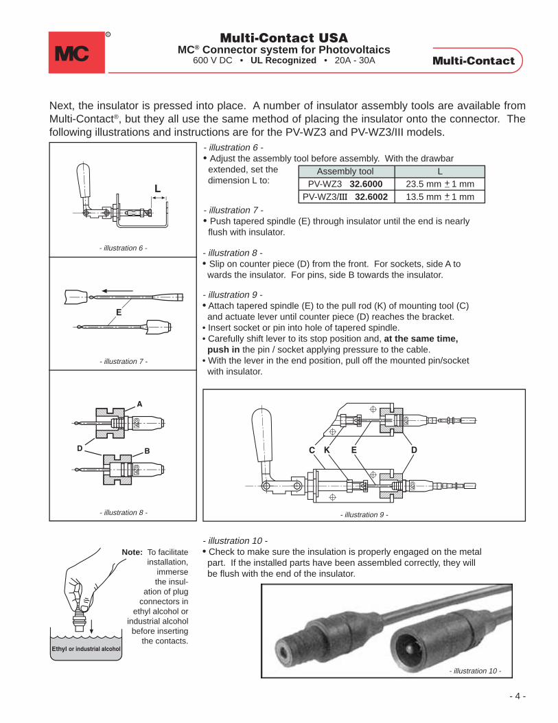
- illustration 6 -- illustration 8 -• Slip on counter piece (D) from the front. For sockets, side A to wards the insulator. For pins, side B towards the insulator.
- illustration 7 -• Push tapered spindle (E) through insulator until the end is nearly flush with insulator.
- illustration 9 -• Attach tapered spindle (E) to the pull rod (K) of mounting tool (C) and actuate lever until counter piece (D) reaches the bracket.• Insert socket or pin into hole of tapered spindle.• Carefully shift lever to its stop position and, at the same time, push in the pin / socket applying pressure to the cable.• With the lever in the end position, pull off the mounted pin/socket with insulator.
- illustration 6 -• Adjust the assembly tool before assembly. With the drawbar extended, set the dimension L to:
Next, the insulator is pressed into place. A number of insulator assembly tools are available fromMulti-Contact®, but they all use the same method of placing the insulator onto the connector. Thefollowing illustrations and instructions are for the PV-WZ3 and PV-WZ3/III models.
- illustration 10 -• Check to make sure the insulation is properly engaged on the metal part. If the installed parts have been assembled correctly, they will be flush with the end of the insulator.
Note: To facilitateinstallation,
immersethe insul-
ation of plugconnectors in
ethyl alcohol orindustrial alcoholbefore inserting
the contacts.
- illustration 10 -
L23.5 mm 1 mm13.5 mm 1 mm
Assembly toolPV-WZ3 32.6000
PV-WZ3/III 32.6002
++
- illustration 9 -
Multi-Contact USAMC® Connector system for Photovoltaics
600 V DC • UL Recognized • 20A - 30A

Finally, affix the supplied “DO NOT DISCONNECT UNDER LOAD” label just below the finishedcable termination using the following procedures:
a. Peel tag from backingb. Align * along the wirec. Match pip ▲ to pip ▲ .d. Press adhesive sides together, keeping fingertips off of adhesive
When attaching finished connectors, make sure that they are fully engaged, leaving no gap betweenthe insulators. It is recommended to slightly twist the connectors during mating to ensure properengagement.
- 5 -
Multi-Contact USAMC® Connector system for Photovoltaics
600 V DC • UL Recognized • 20A - 30A
Once the connectors are fully assembled and fully engaged it is important to make sure that thecable is properly routed, with no sharp bends or twists. Refer to the cable manufacturers’specification for minimum bending radii.
CORRECT Engagement
CORRECT Routing of Cable INCORRECT Routing of Cable
INCORRECT Engagement
GAP
SHARP RADIUS

Derating diagram of a single PV-Connection
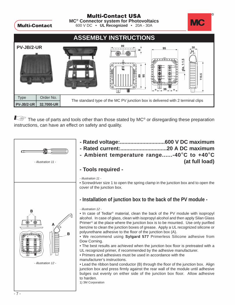
PV-JB/2-UR
Type Order No.
PV-JB/2-UR 32.7000-URThe standard type of the MC PV junction box is delivered with 2 terminal clips
- CAUTION -Unplugging Under Load: PV plug connections must not be unplugged while underload. They can be placed in a no load state by switching off the DC / AC convertor orbreaking the AC circuit. Plugging and unplugging while under voltage is permitted.
Junction Box - Model PV-JB/2-UR
Rated voltage: 600V Rated current: 20 AAmbient temperature range: -40°C to +40°C (at full load)
- 6 -
- “PLUG-N-PLAY” JUNCTION BOXES -
Multi-Contact USAMC® Connector system for Photovoltaics
600 V DC • UL Recognized • 20A - 30A
ASSEMBLY INSTRUCTIONSPV-JB/2-UR
Type Order No.
PV-JB/2-UR 32.7000-URThe standard type of the MC PV junction box is delivered with 2 terminal clips
The use of parts and tools other than those stated by MC® or disregarding these preparationinstructions, can have an effect on safety and quality.
- illustration 11 -
• Screwdriver size 1 to open the spring clamp in the junction box and to open thecover of the junction box.
- Tools required -
- Installation of junction box to the back of the PV module -
- illustration 11 -
- illustration 12 -
- illustration 12 -
• In case of Tedlar® material, clean the back of the PV module with isopropylalcohol. In case of glass, clean with isopropyl alcohol and then apply Silan GlassPrimer1) at the place where the junction box is to be mounted. Use only purifiedbenzine to clean the junction boxes of grease. Apply a UL recognized silicone orpolyurethane adhesive to the floor of the junction box (A).• We recommend using Sylgard 577 Primerless Silicone adhesive fromDow Corning.• The best results are achieved when the junction box floor is pretreated with aUL recognized primer, if recommended by the adhesive manufacturer.• Primers and adhesives must be used in accordance with themanufacturer’s instructions.• Lead the ribbon band conductor (B) through the floor of the junction box. Alignjunction box and press firmly against the rear wall of the module until adhesivebulges out evenly on either side of the junction box floor. Allow adhesiveto harden.1) 3M Corporation
- Rated voltage:..............................600 V DC maximum- Rated current:...............................20 A DC maximum- Ambient temperature range......-40°C to +40°C
(at full load)
- 7 -
Multi-Contact USAMC® Connector system for Photovoltaics
600 V DC • UL Recognized • 20A - 30A
ASSEMBLY INSTRUCTIONS
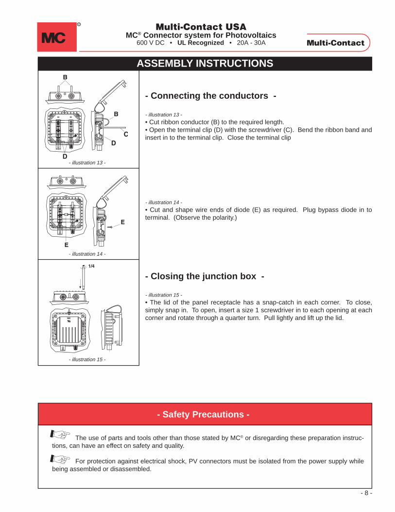
- illustration 13 -
• Cut ribbon conductor (B) to the required length.• Open the terminal clip (D) with the screwdriver (C). Bend the ribbon band andinsert in to the terminal clip. Close the terminal clip
- Connecting the conductors -
- illustration 14 -
• Cut and shape wire ends of diode (E) as required. Plug bypass diode in toterminal. (Observe the polarity.)
- illustration 15 -
• The lid of the panel receptacle has a snap-catch in each corner. To close,simply snap in. To open, insert a size 1 screwdriver in to each opening at eachcorner and rotate through a quarter turn. Pull lightly and lift up the lid.
- Closing the junction box -
- illustration 15 -
- illustration 13 -
- illustration 14 -
The use of parts and tools other than those stated by MC® or disregarding these preparation instruc-tions, can have an effect on safety and quality.
For protection against electrical shock, PV connectors must be isolated from the power supply whilebeing assembled or disassembled.
- Safety Precautions -
- 8 -
Multi-Contact USAMC® Connector system for Photovoltaics
600 V DC • UL Recognized • 20A - 30A

+
-
ASSEMBLY INSTRUCTIONS
- illustration 1 -
• Assembly device PV-RWZ including tapered spindle PV-KOI+II and PV-KOIII for connector sizes I+II or III. (OrderNo. 32.6009). Assembly tool for the simple assembly of individual plug connections with leads cut to correct length onsite. We shall also be pleased to supply you with ready-assembled solar cables.
Multi-Contact USAMC® Connector system for Photovoltaics
600 V DC • UL Recognized • 20A - 30A
- illustration 1 -
- illustration 2 -
Before assembly, pull and turn the counter piece in the required position.• For socket insulation the “+” towards the top.• For pin insulation the “-“ towards the top.
Then hold down the rest lever and push back the counter piece up to the pullhead.
- illustration 2 -
PV US01 ASSEMBLY INSTRUCTIONS APPENDIX AOPERATING INSTRUCTIONS FOR ASSEMBLY TOOL PV-RWZ AND:
PV Female Cable Coupler PV-KBT3...PV-Male Cable Coupler PV-KST3...
-Appendix A-1 -
Pull rod
Counter pieceTapered spindlePull pin
Pull head
Lever
Tools required
Pos. Type Order No. Description
1 P V-BP3/4 32.0100 Socket Ø 3 mm1 P V-BP3/6 32.0101 Socket Ø 3 mm2 P V-T3I/B UR 32.0700 UR Socket insulator2 P V-T3II/B UR 32.0702 UR2 P V-T3III/B UR 32.0704 UR3 P V-SP3/4 32.0500 Plug Ø 3 mm3 P V-SP3/6 32.05024 P V-T3I/S UR 32.0701 UR Plug insulator4 P V-T3II/S UR 32.0703 UR4 P V-T3III/S UR 32.0705 UR
Socket insulatorSocket insulator
Plug Ø 3 mm
Plug insulatorPlug insulator
PV -R WZ PV -KOI+II
PV -KOIIIReset lever
1
PV-BP3/... PV-T3.../B UR
PV-SP3/... PV-T3.../S UR
4
2
3

Industrial alcohol
Lever
- illustration 3
• Select the tapered spindle: PV-KOI+II (Order No. 32.6016) for socket- andpin-insulation size I+II, PV-KOIII (Order No. 22.6017) for socket- and pin-insulation size III.
Push tapered spindle through insulator until the pull pin protrudes approx. 2.5cm out of the insulator.
- illustration 4 -
• Push tapered spindle through the counter piece…
- illustration 5 -
• …and engage in the pull head.
- illustration 6 -
• Insert socket or pin with crimped cable intothe tapered spindle up to the stop position.Keep hold of the cable in position and pressthe lever several times to draw the spindlethrough the socket or pin insulator seated inthe counter piece, until the insulator graspsthe cable. Afterwards, to completely drawthe spindle out of the socket resp. pininsulator, continue pressing the lever.
- illustration 7 -
• Take the socket or pin out of thecounter piece and lightly pull backthe cable to make sure the insulatoris properly engaged on the metalpart. If the installed parts have beenassembled correctly, they will beflush with the end of the insulator.
- illustration 3-
- illustration 5 -
- illustration 4 -
- illustration 6 -
- illustration 7 -
-Appendix A-2 -
- illustration 8 -
• Note:The installation can be facilitatedwhen the insulation of plug connec-tors is immersed in industrialalcohol before inserting contacts.
- illustration 8 -
PV-KOIII
PV-KOI+II
~2,5 cm
~2,5 cm
Multi-Contact USAMC® Connector system for Photovoltaics
600 V DC • UL Recognized • 20A - 30A
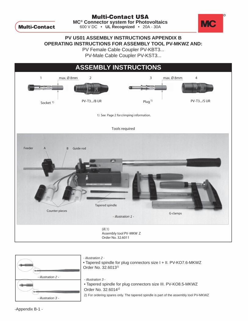
Feeder A B Guide rod
G-clampsCounter pieces
Tapered spindle
Tools required
1
Socket 1) Plug
max. Ø 8mm max. Ø 8mm
PV-T3.../B UR PV-T3.../S UR
2 3 4
(ill.1)Assembly tool PV-MKW ZOrder No. 32.6011
1) See Page 2 forcrimping i nformation.
1)
Multi-Contact USAMC® Connector system for Photovoltaics
600 V DC • UL Recognized • 20A - 30A
-Appendix B-1 -
PV US01 ASSEMBLY INSTRUCTIONS APPENDIX BOPERATING INSTRUCTIONS FOR ASSEMBLY TOOL PV-MKWZ AND:
PV Female Cable Coupler PV-KBT3...PV-Male Cable Coupler PV-KST3...
ASSEMBLY INSTRUCTIONS
- illustration 2 -
• Tapered spindle for plug connectors size I + II. PV-KO7.6-MKWZOrder No. 32.60132)
- illustration 3 -
• Tapered spindle for plug connectors size III. PV-KO8.5-MKWZOrder No. 32.60142)
2) For ordering spares only. The tapered spindle is part of the assembly tool PV-MKWZ
- illustration 1 -
- illustration 2 -
- illustration 3 -

Industrial alcohol
7-10
mm
2.5
II + I II + I
III III
A
P
Industrial alcohol
K
- illustration 4 -
• Counter pieces for plug connectors size I + II, and III (white for sockets, blackfor plugs)
-Appendix B-2 -
- illustration 8 -
- illustration 7 -
- illustration 5-
- illustration 4 -
- illustration 6-
- illustration 9 -
- illustration 10 -
- illustration 5 -
• Hex. key wrench 2.5 mm.
- illustration 6 -
• Vessel with industrial alcohol.
- illustration 7 -
• Secure the assembly device on a stable working bench with 2 G-clamps.
- illustration 8 -
• Before every assembly action move the feeder (A) in the engage position (P).
- illustration 9 -
• To facilitate installation immerse the connector insulations in industrial alcoholbefore inserting the contacts.
- illustration 10 -
• Push tapered spindle (K) through insulator. (Observe the size I + II or III).
Multi-Contact USAMC® Connector system for Photovoltaics
600 V DC • UL Recognized • 20A - 30A

KG
G
G
Z
Z
H
M
Multi-Contact USAMC® Connector system for Photovoltaics
600 V DC • UL Recognized • 20A - 30A
-Appendix B-3 -
- illustration 11 -
- illustration 11 -
• Push tapered spindle (K) with insulator through counter piece (G) (whitecounter piece for sockets, black counter piece for plugs, observe the size I + IIor III).
- illustration 14-
- illustration 13 -
- illustration 12-
- illustration 15 -
- illustration 15 -
• Take out the assembled cable and check to make sure the insulator isproperly engaged on the metal part. If the installed metal parts have beenassembled correctly, they will be flush with the end of the insulator.
- illustration 12 -
• Put the counter piece (G) into the two guide rods, at the same time attachtapered spindle (K) to the pull rod (Z).
- illustration 13 -
• Open feeder jaws (H) and at the same time push socket or plug with crimped-on cable into the cone as far as it will go. Close feeder jaws by releasing.
- illustration 14 -
• To activate the assembly process carefully shift lever (M) to its stop positionwith a regular movement.
B S
_+
B
K
+ -
-Appendix B-4 -
- illustration 17-
- illustration 16-
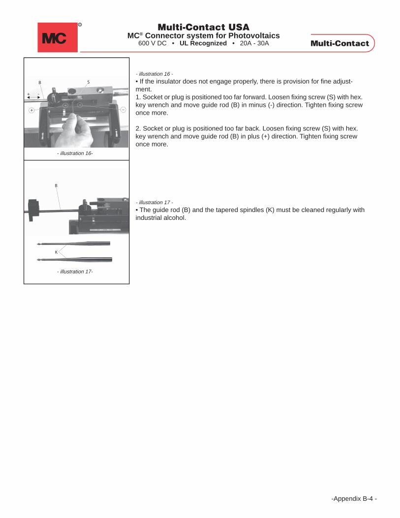
- illustration 17 -
• The guide rod (B) and the tapered spindles (K) must be cleaned regularly withindustrial alcohol.
- illustration 16 -
• If the insulator does not engage properly, there is provision for fine adjust-ment.1. Socket or plug is positioned too far forward. Loosen fixing screw (S) with hex.key wrench and move guide rod (B) in minus (-) direction. Tighten fixing screwonce more.
2. Socket or plug is positioned too far back. Loosen fixing screw (S) with hex.key wrench and move guide rod (B) in plus (+) direction. Tighten fixing screwonce more.
Multi-Contact USAMC® Connector system for Photovoltaics
600 V DC • UL Recognized • 20A - 30A

- For U.S. Distribution Only -- For U.S. Distribution Only -
Regional Sales Offices:CANADA4870 Baytree CourtBurnaby, BC, Canada V5G 4H3Tel. (604) 451-7808Fax (604) 451-7809
WEST5560 Skylane Blvd.Santa Rosa, CA 95403Tel. (707) 575-7575Fax (707) 575-7373
SO. CALIFORNIA / SOUTHWEST2061 PuebloTustin Ranch, CA 92782Tel. (714) 832-8166Fax (714) 832-5978
MIDWEST901 Winslow AvenueWoodstock, IL 60098Tel. (815) 334-9530Fax (815) 334-9529
SOUTH-CENTRAL808 Timber TrailCedar Park, TX 78613Tel. (512) 331-9824Fax (512) 331-9856
GREAT LAKES / SOUTHEAST3348 Innsbrook DriveRochester Hills, MI 48309Tel. (248) 375-8140Fax (248) 375-8141
NORTHEAST35 Hemlock DriveNorwell, MA 02061Tel. (781) 659-9399Fax (781) 659-9383
MID-ATLANTIC5055 Brightwood RoadBethel Park, PA 15102Tel. (412) 833-3886Fax (412) 833-4406
- Created: August, 2005 -- Modified: January, 2007 - Revision E -
Multi-Contact USAMC® Connector system for Photovoltaics
600 V DC • UL Recognized • 20A - 30A
SOUTHEAST3814 Lace Vine LaneBoynton Beach, FL 33436Tel. (561) 739-6394Fax (561) 739-6395