multi-channel analysis of surface waves (masw) applied to
TRANSCRIPT

Multi-channel analysis of surface waves (MASW) applied to an active fault zone
Jessie M Arthur [email protected]
Supervisor: Dr. Don C. Lawton

Outline
1. Introduction: Objectives, MASW
2. Geologic Setting & Data Acquisition
3. Data Processing
4. Dispersion Analysis
5. Preliminary Inversion Results
6. Future Work

Objectives
1. Apply the MASW method to delineate a
known fault zone
2. Identify soil conditions that have risk for
high liquefaction potential

MASW (Park et al., 1999)
• Goal is to generate a Vs profile though multi-channel analysis of surface waves (ground roll)
• Dispersion: For each unique frequency component of a surface wave, a different propagation velocity exists.
Acquisition of
broadband
ground roll
Extract
Rayleigh wave
dispersion
curves
Invert Rayleigh
wave phase
velocities for S-
wave velocity
profiles
PROCESSING

Copyright 2004. L. Braile. Permission granted for reproduction and use of files and animations for non-commercial uses
Animation source: L. Braile, Purdue University, www.eas.purdue.edu/~braile
Rayleigh Wave Animation

Greendale Fault
Geology map source: GNS Science QMap series
Line 3
Geologic Setting

641
306
MASW ANALYSIS
LINE 3
GEOPHONES Sensor SM-24 10 Hz vertical component
SEISMIC SOURCE IVI Envirovibe. 10 – 120 Hz Sweep, 10 sec, 8 sweeps.
RECORDER 4000 ms recording length, 1 ms sample rate
Data acquisition parameters . . . Receiver Spacing = 10 m
. . . Shot Spacing = 10 m
STN 440
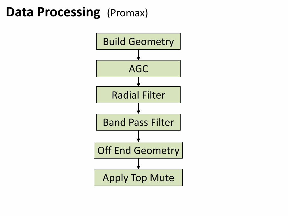
Data Processing (Promax)
Build Geometry
AGC
Radial Filter
Band Pass Filter
Off End Geometry
Apply Top Mute

A feel for the data…
869 m/s
339 m/s
2508 m/s
450 m/s

A feel for the data…
40 Hz
Shot 500 AGC 1000

Shot 390 Raw
Data Processing

Shot 390 BP Filt 0-4-30-36
Data Processing

Shot 390 BP Filt 0-4-30-36 & AGC 1000
Data Processing

Shot 380 – Raw with AGC (Mean with OpLen=1000). Gain = 1.5
Data Processing: Radial Filter (Max low f = 30Hz)

Shot 380 – What I am keeping (Post-Radial Filter)
Data Processing: Radial Filter (Max low f = 30Hz)

Shot 380 – What I am throwing away
Data Processing: Radial Filter (Max low f = 30Hz)

Shot 410 – Raw with AGC (Mean with OpLen=1000). Gain = 1.5
Data Processing: Radial Filter (Max low f = 30Hz)

Shot 410 – What I am keeping (Post-Radial Filter)
Data Processing: Radial Filter (Max low f = 30Hz)

Shot 410 – What I am throwing away
Data Processing: Radial Filter (Max low f = 30Hz)

SHOT 500: AGC. Before Radial Filter
Data Processing

SHOT 500: AGC. After Radial Filter 30 Hz max
Data Processing

POST RADIAL FILT: No Mute
Data Processing

POST RAD FILTER: WITH TOP MUTE
Data Processing

POST RADIAL FILTER Mute & Off-END GEOM
Data Processing

Dispersion Analysis WITH KGS SURFSEIS
1. Create the best overtone image as possible to analyze changing phase velocity patterns with frequency.
2. Find best parameters to pick dispersion curve
PH
ASE
VEL
OC
ITY
(m/s
)
FREQUENCY (Hz)

Shot 360 Offset: 0 - 500 m
Time: 0 – 1600 ms

Shot 360: Phase Velocity: 0 – 10000 m/s Frequency: 6 – 40 Hz
Dispersion Analysis: THE BIG PICTURE

Dispersion Analysis: Within the expected range
Shot 360: Phase Velocity: 0 – 1000 m/s Frequency: 6 – 40 Hz

Dispersion Analysis SHOT 338

Dispersion Analysis SHOT 412

Dispersion Analysis SHOT 425

Dispersion Analysis SHOT 450

S-WAVE VELOCITY MODEL SHOT 450

Preliminary Inversion Results Initial model created from each dispersion curve
DEP
TH (
m)

DEP
TH (
m)
RMS Error

Future Work
1. Consider applying additional FK Filters
2. Analysis of left Off-End records
3. Further analysis of inversion parameters
4. Interpretation of results
5. Consider all suggestions from today’s meeting!

Thank you
• Helen Isaac and Malcolm Bertram • David Henley • Kevin Hall • Roohollah Askari • CREWES Sponsors

References
Park, C.B., R.D. Miller, and J. Xia, 1999, Multichannel analysis of surface waves, Geophysics, 64, 800-808.