multi-beam mimo prototype for real-time multiuser ... · multi-beam mimo prototype for real-time...
TRANSCRIPT
Multi-Beam MIMO Prototype for Real-TimeMultiuser Communication at 28 GHz
John Brady, John Hogan, and Akbar SayeedDepartment of Electrical and Computer Engineering
University of Wisconsin - Madison
Abstract—The rapid proliferation of data hungry devices iscreating a bandwidth crisis, with aggregate data rates expectedto increase 1000 fold between 2010 and 2020. Millimeter-wave(mmW) systems operating in the 30-300 GHz band are poised tomeet this exploding demand through large bandwidths and high-dimensional MIMO operation. However conventional MIMOtechniques result in prohibitively high complexity, and existingphased array based mmW prototypes are only capable ofsupporting a single beam. In this paper, we report new results ona Continuous Aperture Phased (CAP) MIMO prototype systemthat uses a lens array for analog multi-beamforming to achievenear-optimal performance with a dramatically lower transceivercomplexity. We discuss the main components of the CAP-MIMOprototype design and present initial experimental results on anFPGA-based real-time implementation of a point-to-multipointmultiuser link at 28 GHz. Directions for future research anddevelopment are also briefly discussed.
Index Terms—millimeter-wave wireless, Gigabit wireless, high-dimensional MIMO, massive MIMO, beamforming
I. INTRODUCTION
Capacity demands on wireless networks are growing expo-
nentially due to the proliferation of data-hungry devices. In
networks operating below 5 GHz small cells that leverageincreased spatial reuse of the spectrum [1] and multiple-
input multiple-output (MIMO) technology for managing in-terference and increasing spectral efficiency [2], [3] are the
two main approaches to addressing this challenge. Emerging
millimeter wave (mmW) systems, operating from 30-300 GHz,represent a complementary, synergistic opportunity due to
orders-of-magnitude larger available bandwidths and small
wavelengths that enable high-dimensional MIMO operation[4]–[6]. The large number (n) of MIMO degrees of freedom
can be exploited for a number of critical capabilities including:
higher beamforming gain; higher spatial multiplexing gain;and highly directional communication with narrow beams.
In mmW links the number of spatial communication modes
(beams) p is typically much smaller than the spatial sig-
nal space dimension n due to the expected sparsity ofthe propagation environment in beamspace [7]. Conventional
MIMO systems based on digital beamforming suffer fromprohibitively high O(n) transceiver complexity. Phased array
based systems for analog beamforming have been proposed to
reduce complexity, but in practice such systems are limited toa single beam; all recent phased array prototypes from leading
companies suffer from this limitation [8]–[11]. In contrast,
the Continuous Aperture Phased (CAP) MIMO transceiver
This work is partly supported by the NSF under grants ECCS-1247583, IIP-1444962, ECCS-1548996, and the Wisconsin Alumni Research Foundation.
architecture proposed in [4]–[6] uses a lens array for ana-log multi-beamforming to exploit the concept of beamspace
MIMO (B-MIMO) communication [12] and achieves the crit-
ical operational functionality of multi-beam steering and datamultiplexing (MBDM) with only O(p) transceiver complexity.
This paper builds on previous CAP-MIMO prototypingefforts [13] at 10 GHz and reports on a state-of-the-art 28
GHz point-to-multipoint (P2MP) prototype that provides a
compelling demonstration of CAP-MIMO’s unique MBDMcapability at mmW. Section II reviews B-MIMO theory and
the CAP-MIMO architecture. Section III details the hardware
implementation of the novel CAP-MIMO beamforming archi-tecture and the communication frame that enables dynamic
beam selection and tracking and orthogonal frequency division
multiplexing (OFDM) signaling for low-complexity multiusertemporal and spatial equalization. Section IV presents initial
results based on a real-time implementation of the frame using
field programmable gate arrays (FPGAs). Concluding remarksare provided in Sec. V.
II. BEAMSPACE MIMO THEORY
A. Sampled MIMO System Representation
It is well-known that an antenna aperture can be equivalentlyrepresented by its half-wavelength sampled version without
any loss of information [4], [14]. The number of samples, n,
represents the dimension of the 2D spatial signal space andalso determines the directivity or beamforming gain G:
n =4A
λ2, G = 10 log
10(πn) (1)
where A is the antenna area. The baseband uplink communi-cation model between K single antenna mobile stations (MSs)
and an access point (AP) with an antenna of area A is
r(f) = H(f)s(f) +w(f) , −W/2 ≤ f ≤ W/2 (2)
where r(f) is the (vectorized) n-dimensional aperture domain
receive signal vector, H(f) = [h1(f), . . .hK(f)] is the n×Kaperture domain channel matrix that represents the couplingbetween the n-dimensional aperture domain signal at the AP
samples and the K MSs, s(f) is the K-dimensional trans-
mitted signal vector, w(f) represents additive white Gaussiannoise (AWGN) with power spectral density No, and W is the
system bandwidth. OFDM signaling with symbol length M(in 1/W spaced samples) results in a sampled representationof the system with ∆f = W/M
r[m] = H[m]s[m] +w[m] , H[m] = [h1[m], . . . ,hK [m]]
m = −⌊M/2⌋ , . . . , 0, . . . , ⌈M/2⌉ − 1 (3)
where r[m] = r(m∆f) is the sampled signal, m is the OFDM
subcarrier index, s[m] is the transmit signal vector at the m-thsubcarrier, and w[m] ∼ CN (0, σ2I) with σ2 = NoW/M .
B. Beamspace MIMO System Representation
In B-MIMO theory the aperture domain system is equiva-
lently represented in the beamspace domain and the two are
related through a spatial Fourier transform [4], [5], [12]. Let Urepresent the n×n 2D DFT matrix whose columns represent northogonal beam directions [4], [5]. The sampled beamspace
OFDM system representation is obtained from (3) via fixedbeamforming at the receiver rb[m] = UHr[m]:
rb[m] = Hb[m]s[m] +wb[m] , Hb[m] = UHH[m]
Hb[m] = [hb,1[m], . . . ,hb,K [m]] (4)
where hb,k[m] is the beamspace channel vector for the k-
th MS. The critically (λ2) sampled aperture domain and
beamspace domain representations are equivalent since U isa unitary matrix: UHU = UUH = I. That is, (critically)
sampling the system in the aperture domain is equivalent
to (critically) sampling the system in beamspace. Criticalsampling in beamspace is related to the beamwidth which is
approximately given by δφ = λD for circular apertures with
diameter D [4], [5].
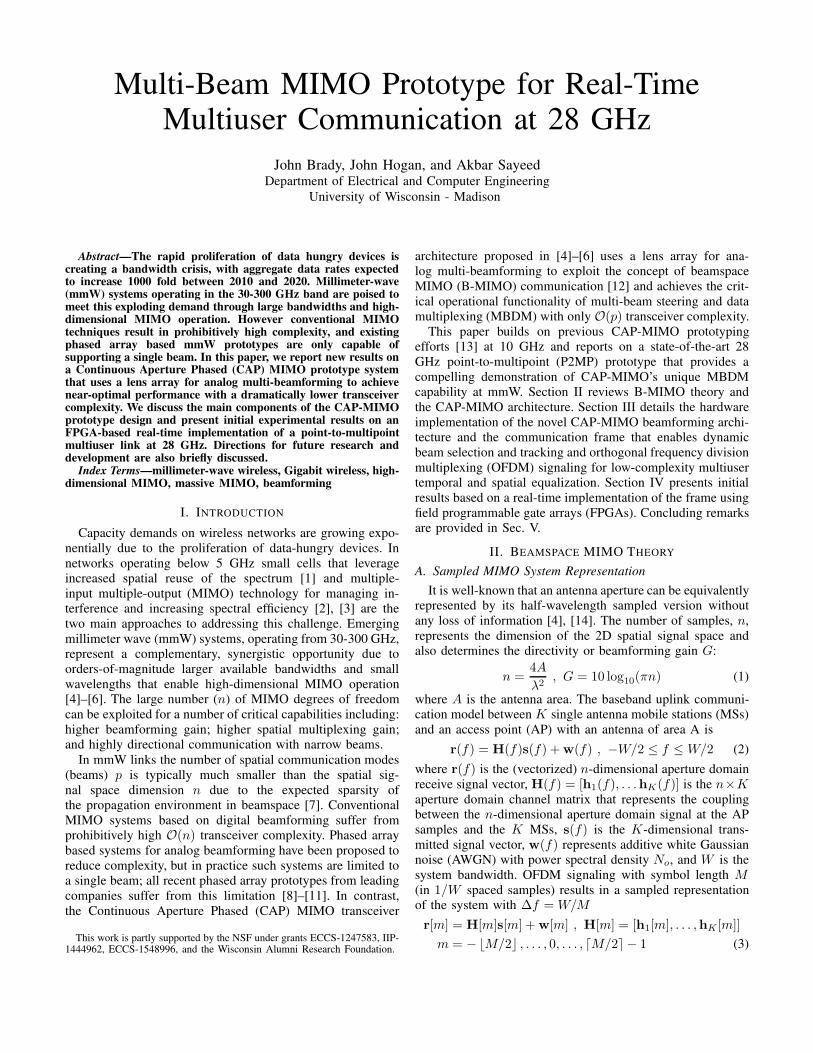
In the CAP-MIMO prototype, illustrated in Fig. 1, the
unitary DFT matrix is realized with a lens array (a lensantenna combined with a feed antenna array) that performs
fixed analog multi-beamforming [4]. The placement of the
feed antennas on the lens’s focal surface corresponds to criticalsampling in beamspace.
Fig. 1: Schematic of a CAP-MIMO transceiver showing the p RFchains (blue), beam selector hardware, and lens array which performsanalog multi-beamforming.
C. Beam Selection
Due to the highly directional nature of propagation at mmW,
LoS propagation is expected to be the dominant mode, with
some additional sparse (single-bounce) multipath componentspossible in urban environments [15]–[17]. This leads to the
key property of beamspace channel sparsity. In CAP-MIMO,beamspace channel sparsity and lens array based analog beam-
forming are exploited to reduce transceiver complexity from
O(n) (DSP and RF) complexity to O(p) complexity throughbeam selection; see Fig. 1. The beam sparsity mask for a given
channel is computed by selecting multiple beam indices that
maximize the power-based metric [18], [19]:
M = argmaxi
K∑
k=1
⌈M/2⌉−1∑
m=−⌊M/2⌋
|hb,ik[m]|2 (5)
where hb,ik[m] is the i-th element of hb,k[m] representing thecoupling between the k-th MS and the i-th orthogonal beam.
The link budget p (number of spatial I/Q channels) controls
how many beams we can select. In general p ∼ O(bK) isneeded to support K MSs, with b depending on how many
propagation paths there are for each MS. In LoS channels, b =2 yields near-optimal performance [19]. The low-dimensional
B-MIMO system induced via beam selection is
r̃b[m] = H̃b[m]s[m] + w̃b[m] (6)
where the tilde notation ( ·̃ ) represents the p-dimensional
receive beamspace signal vectors, i.e. r̃b[m] = [rb,i[m]]i∈M
and H̃b[m] = [hb,ik[m]]i∈M,k=1,...,K .
In CAP-MIMO transceivers this low-dimensional system isdirectly accessed via a lens array and mmW beam selector,
resulting in dramatically reduced O(p) complexity. Conven-
tional digital beamforming transceivers, on the other hand,can only access this low-dimensional system after sampling
the aperture domain signal with n spatial I/Q channels and
applying a p × n beamforming matrix in digital hardware,resulting in prohibitive O(n) complexity.
D. Transceiver Design
Under the assumption that there is no inter-carrier inter-
ference (ICI), the minimum mean squared error (MMSE)space-frequency receiver corresponds to individually applying
a K × p spatial MMSE receiver to r̃b[m] at each subcarrier:
FMMSE[m] = H̃Hb [m]
(
H̃b[m]H̃Hb [m] + σ2In
)−1
. (7)
In the prototype this requires p fast Fourier transforms (FFTs)to transform the received signal into the frequency domain,
which is slightly too complex for the current FPGA (see
Sec. III-A). Thus the prototype uses a simplified transceiverconsisting of a frequency flat spatial filter applied in the time
domain followed by K scalar frequency domain equalizers(FDEs) to reduce the number of FFTs from p to K .
This simplification is based on two key assumptions 1
First, that each element of H̃b[m] is frequency flat. This
is expected to be the case for sparse channels since each
dominant beam will capture approximately one propagationpath. Second, that each MS’s beamspace channel is separable
in space and frequency, i.e hb,k[m] = hb,k,ogk[m] where
gk[m] is the normalized scalar frequency response of the k-th MS, with |gk[m]|2 = 1 from the first assumption. Using
these assumptions and applying the matrix inversion lemma,
the space-frequency MMSE receiver (7) can be written as [18]
FMMSE[m] = GH [m](
H̃Hb,oH̃b,o + σ2IK
)−1
H̃Hb,o (8)
= GH [m]FMMSE,o (9)
where FMMSE,o is the K×p frequency flat MMSE spatial filter
calculated from H̃b,o = [hb,1,o, . . . ,hb,K,o] and GH [m] =diag(g∗
1[m], . . . , g∗K [m]) represents K scalar phase only FDEs
applied to the spatially filtered receive signals of the MSs. Note
that in practice non-idealities in the transceiver componentswill introduce amplitude variations across frequency, even for
completely flat channels, so we replace the phase only FDE
determined by g∗k[m] with a FDE determined by g−1
k [m].
1The applicability of these assumptions has been tested and shown tohold in the indoor environments used for initial prototype testing via offlineprocessing of raw received data (see Sec. IV).

III. PROTOTYPE DESIGN
This section discusses the design of the P2MP prototype
equipped with a CAP-MIMO transceiver at the AP usedto demonstrate the key MBDM functionality in a real-time
communication system operating at an industry relevant mmW
frequency of 28 GHz. Detailed block diagrams of the proto-type CAP-MIMO AP and single antenna MSs are shown in
Fig. 2(a) and (b). The AP prototype supports p = 4 spatial
RF channels – two channels are shown in Fig. 2(a) – andenables B-MIMO communication through a lens-based front-
end and a beam selector. Two MSs were constructed for
the prototype. We note that while the block diagrams showthe AP and MSs equipped with transmit/receive chains for
bidirectional operation, for this initial stage of prototyping the
system is configured for unidirectional uplink communicationwith p = 4 receive chains at the AP and a single transmit
chain at each MS.
A. Prototype Specifications and Components
sI,1[n]
sQ,1[n]
rI,1[n]
rQ,1[n]
DAC
ADC
sI,1(t)
sQ,1(t)
rQ,1(t)
rI,1(t)
PA
LNA
BPFCLK
FPGA:
Signal
Proc. &
Control
Switch Control
LO
...Inter-FPGA
Comm. Bus
sI,4[n]
sQ,4[n]
rI,4[n]
rQ,4[n]
DACsI,4(t)
sQ,4(t)
rQ,4(t)
rI,4(t)
PA
LNA
BPF
FPGA:
Signal
Proc. &
Control
Switch Control
ADC
...
......
......
......
......
......
......
......
......
(a)
sI[n]
sQ[n]
rI[n]
rQ[n]
DACsI(t)
sQ(t)
rQ(t)
rI(t)
PA
LNA
BPF
FPGA:
Signal
Proc. &
Control ADC
CLK
LO
(b) (c)
(d) (e)
(f)
(g)
(h)
Fig. 2: (a) Block diagram of the CAP-MIMO based AP, (b) Blockdiagram of the MSs, (c) Lens array diagram, (d) mmW beam selectorconfiguration, (e) Prototype AP hardware, (f) Full prototype system,(g) Prototype lens array, (h) Prototype MS RF hardware
The basic specifications of the prototype system are asfollows:
• Operational frequency: fc = 28 GHz, λ = 10.7 mm
• Operational bandwidth: The mmW circuitry supports abandwidth of up to W = 1 GHz. The ADC/DACs operate
at a sample rate of 125 MHz (limited by the ADCs)• Number of AP spatial I/Q channels: The AP supports
p = 4 spatial I/Q channels.
The AP CAP-MIMO transceiver prototype consists of four
main components as illustrated in Fig. 2(a).
1. FPGA-based DSP back-end and ADCs: The DSP back-
end consists of a Terasic DE4 development and education
board equipped with an Altera Stratix IV FPGA. Two TexasInstruments (TI) ADS6445 125 MHz quad 14-bit ADC eval-
uation modules are interfaced with the FPGA via High SpeedMezzanine (HSMC) connectors to support the p = 4 spatial
I/Q channels at the AP. A TI CDCE62005 clock generator
evaluation module is used to supply the ADCs with the 125MHz sampling clock. The DE4 also includes a PCIe interface
that enables data offload to a host computer.
2. mmW Receive Chains: The mmW circuitry (Fig. 2(e))supports p = 4 receive chains for simultaneously receiving the
signal from the selected beams. Each receive chain consists ofan I/Q mixer, a bandpass filter (BPF), and a low noise amplifier
(LNA). Each chain consists of two (I/Q) sub-channels for
full complex modulation (e.g., QAM), and the 4 channelsare down-converted using a single local oscillator (LO), as
illustrated in Fig. 2(a).
3. Front-End Lens Array: The AP uses a circular lens withdiameter D=6” and focal length f=D=6” (Fig. 2(c) and (g)).
From (1) at 28 GHz this corresponds to a half-wavelength
spaced 2D array with n = 636 elements, antenna gain ofG ≈ 33dBi, and a beamwidth of about 4◦. The feed antenna
array consists of 16 open ended WR-28 waveguides arrangedin a 4 × 4 grid centered at the lens’ broadside focal point as
shown in Fig. 2(c), covering an angular spread of about 16◦
in both azimuth and elevation.
4. mmW Beam Selector: As shown in Fig. 2(a), the mmW
beam selector multiplexes each of the p = 4 mmW receive
chains to a subset of feed antennas. In the prototype, theselector is constructed with four mmW 1 → 4 switches. Each
switch is associated with a single receive chain connected toa disjoint quadrant of 4 feed antennas as shown in Fig. 2(d).
The FPGA controls the setting of each switch via I/O pins
connected to external decoding and level shifting circuitry.
The single antenna MS prototypes consist of two main
components as illustrated in Fig. 2(b)
1. FPGA-based DSP back-end and DACs: As with the
AP, the DSP back end consists of a Terasic DE4. A HSMC
connector is used to interface with a TI DAC3484 quad 16-bitDAC evaluation module configured to operate at a sampling
rate of 125 MHz. The same DSP back end is shared between
the two MSs. Long baseband cables are used to carry the I/QDAC signals for each MS to the transmit IQMs, allowing the
MSs to act independently (see Fig. 2(f)).
2. mmW Transmit Chain: each MS has a single transmit
chain consisting of a I/Q mixer, a BPF, and a power amplifier
(PA). Separate LOs are used for up conversion at each MS.WR-28 waveguides are used as the MS antennas (Fig. 2(h)).

Fig. 3: Prototype communication frame diagram
B. Prototype real-time Communication Protocols
The frame in Fig. 3 is used for real-time communication in
the prototype and is divided into two subframe types whichin turn are divided into different types of signaling blocks.
Each frame consists of a beam selection subframe and MFR
data subframes, which in turn consist of control signaling andMD Data blocks. These parameters (MFR,MD) control how
frequently beam selection and channel estimation occur and
can be adjusted to account for the channel dynamics [19].
The signaling blocks in Fig. 3 are shown with their lengthin samples. OFDM signaling is used during the Channel
Estimation and Data blocks. In both cases subcarriers with
frequency |m∆f | > 54.6875 MHz are unoccupied so that thesymbol energy only occupies the flat portion of the DAC pulse
spectrum. This ensures that sampling clock offset between the
MSs and the AP only manifests as a linear phase shift acrosssubcarriers that is removed by the FDE [20]. Additionally,
a cyclic prefix (CP) consisting of the last 32 time domainsamples of the symbol is appended to the beginning of the
block and a cyclic postfix (CPF) consisting of the first 16
samples of the time domain symbol is appended to the endof the block. This prevents inter-block interference from the
DAC pulse tails and signal spreading due to multipath, as well
as ensuring that subcarrier orthogonality is preserved. Blockslabeled 0 represent times when a MS is not transmitting.
The transmit signal and corresponding receive processing for
the other blocks are as follows. We note that except for theData blocks where both MSs transmit simultaneously with
MMSE interference suppression at the receiver, sequential
transmission is used where one MS is silent while the otheris transmitting to ensure that there is no interference.
1. Beam Selection (BS): The BS transmit signal consists of a
length MBS = 4096 constant power signal. After startup or the
end of a previous frame, the AP enters a power detection statewhere the beam setting for all switches changes from 0-3 (see
Fig. 2(d)) every 512 samples with a power measurement taken
from the last 64 samples in a given setting. The remaining 448samples are used to allow the switching circuitry to stabilize
after a change in setting. Once a power measurement exceeds
a threshold, the next 4 measurements are used to estimate the16× 1 channel power vector for MS1. The AP then waits for
2048 samples to ensure MS1’s BS block has been completedand re-enters the power detection mode. The same process
repeats for MS2’s BS block, obtaining an estimate of its
channel power vector. The MS channel power vectors are thenadded (see (5)), and the AP chooses the beam selection mask
by selecting the highest total power beam in each quadrant.
Additionally, the spatial I/Q channel with the most power foreach MS is recorded.
2. Frame Synchronization (FS): The k-th MS transmits
a length Mfs = 130 time domain correlation signal. This
signal is constructed by transmitting each element of a BPSKsequence that differentially encodes a known length Mfs/2−1 = 64 pseudorandom BPSK sequence sfs,k[ℓ] twice.
At the AP, the receive signal on the spatial I/Q channel with
the most power for the k-th MS is routed to a differentialBPSK detector that operates on samples separated by two
sample periods. The previous MFS − 2 = 128 outputs of
the detector are stored at each sample period, and the evenelements are correlated with sfs,k[ℓ]. The correlator output is
compared to a threshold, and when the threshold is exceeded
a frame counter for the k-th MS is activated. This counterincrements every receive sample period and is used to provide
a timing reference that the AP uses to delineate the boundaries
of the CE and Data blocks for the k-th MS.
3. Channel Estimation (CE): The length MT,CE = 560 CEtransmit signal is constructed by repeating a length MCE = 64(1.95 MHz subcarrier spacing) OFDM CE symbols sCE [m]8 times with the CP/CPF appended to beginning and end ofthe repeated sequence. This CE symbol is a constant modulus
chirp occupying the subcarriers −28 ≤ m ≤ 28 sCE [m] .
At the AP, after discarding the CP/CPF, the 8 repetitions of
CE symbol for the k-th MS are averaged to obtain the averagereceived CE symbol:
r̃b,k,CE [m] = h̃b,k[m]sCE [m] +wCE[m] . (10)
The frequency flat spatial channel vector for the k-th MS isthen estimated as
ˆ̃hb,o,k =
1
57
28∑
m=−28
r̃b,k,CE [m]s∗CE [m] . (11)
After h̃b,o,k has been estimated for both MSs, the frequency-
flat spatial filter FMMSE,o can be calculated according to (9).
Then k-th row of FMMSE,o is be applied to r̃b,k,CE [m] toobtain an estimate of the normalized frequency response for
the k-th MS gk[m] which is used to calculate the FDE.
Linear interpolation in the frequency domain is used to
extend the FDE to the larger block size, and correspondingfiner sampling in frequency, of the Data block.
4. Data: The Data blocks consist of MT = 1072 samples
corresponding to a length M = 1024 OFDM symbol (122.07
kHz subcarrier spacing) with the CP/CPF. The OFDM sym-bol corresponds to 896 frequency domain QAM information

(a)
I-0.1 0 0.1
Q
-0.15
-0.1
-0.05
0
0.05
0.1
(b)I
-50 0 50
Q
-50
0
50
(c)I
-5 0 5
Q-5
0
5
(d)
Fig. 4: (a) Raw receive samples at the AP on the strongest spatialI/Q channel for MS1, (b) Received OFDM symbols without spatialfiltering or FDE, (c) Received OFDM symbols with spatial filteringonly, (d) Received OFDM symbols with spatial filtering and FDE
symbols. The information symbols occupy the subcarriers in
the ranges −448 ≤ m ≤ −1 and 1 ≤ m ≤ 448. During Data
blocks both MSs transmit simultaneously.At the AP, the 4 receive time-domain sample streams are
passed through the frequency-flat spatial filter FMMSE,o to
generate a spatially filtered time-domain sample stream foreach MS. Then after discarding the CP/CPF and transforming
the signal into the frequency domain, the FDE is applied toeach OFDM symbol. The output of the FDE for the occupied
subcarriers is then sent to QAM detector to recover the
transmitted information symbols.
C. Digital Hardware Implementation
The receiver was implemented in the FPGA via Altera Quar-tus design software. The beam selection algorithm and hard-
ware for controlling the mmW switches were implemented
directly in Verilog hardware description language (HDL). Allother receive processing was implemented using the DSP
Builder design tool to generate HDL code from algorithms
designed in the MathWorks Simulink environment [21]. APCIe interface was implemented in the FPGA to enable real-
time offload of the processed data. The final implementation
of the receiver uses approximately 90 percent of the FPGAhardware resources, with a significant fraction being allocated
to the K = 2 FFTs needed to transform the spatially filteredreceived signals into the frequency domain. Thus for this initial
prototype using the simplified MMSE receiver (9), based on
the assumptions discussed in Sec. II-D, is critical to achievinga realizable receiver.
IV. RESULTS
In this section, we discuss initial results that demonstratethe ability of the prototype to perform real-time MBDM in
an uplink P2MP setting. The prototype is set up as shown inFig. 2(f). Before real-time operation, the receive processing
algorithms were tested by using the AP FPGA to capture a
snapshot of raw receive samples corresponding to a simpletest frame. This snapshot was then used as input data to a
DSP Builder simulation of the receiver. An example of this
testing is shown in Fig. 4. Fig. 4(a) plots the absolute valueof the raw received signal for the strongest AP spatial I/Q
channel of MS1, showing the FS and CE blocks for both MSsand a block of data. As can be seen from the FS and CE
blocks, there is significant interference from MS2 on MS1’s
dominant channel. Fig. 4(b) shows the frequency domain Datablock samples in I/Q format with no spatial processing or
FDE, clearly showing that the QAM signals intended for MS1
cannot be distinguished. After spatial filtering, as shown inFig. 4(c), it is clear that a significant amount of interference
has been removed. However, the QAM signals are still not
distinguishable due to phase rotation introduced by samplingclock offset and amplitude variation across frequency. Only af-
ter the FDE is applied do the QAM signals become distinct, as
shown in Fig. 4(d), enabling the AP to detect the informationtransmitted by the MSs.
After verifying the frame algorithms in DSP builder, the
AP FPGA is loaded with the real-time processing designthat includes beam selection, which corresponds to the full
frame shown in Fig. 3. The FPGA is connected via PCIe
to a computer running a program that displays the receivedconstellations after spatial filtering and equalization as well as
the the currently selected AP beams in each quadrant overlaid
on a diagram of the feed array (cf. Fig. 2(d)). Fig. 5 showsseveral images taken during a test run of the prototype with
the real-time processing design (video of this test can befound at http://dune.ece.wisc.edu/?page id=385). The received
constellations of MS1 and MS2 are shown on the left in
yellow and on the right in green respectively. The dominantbeam for each MS (reflecting its LoS location) is indicated
by the green/yellow indicator in the currently selected beam
display. Fig. 5(a)-(f) represent a sequence of images takenduring the test as MS1 is moved to demonstrate the dynamic
beam selection and tracking and real-time communication
capabilities of the prototype. Fig. 5(a) shows the startingposition of the MSs with MS1 located in the bottom left
corner of the prototype AP coverage area, which geometrically
maps to the top right beam of the 16-element feed array.From Fig. 5(b)-(e) it is clear from the dominant selected
beam that MS1 is being tracked by the AP as it moves up
vertically, towards the center, and then back down. Meanwhile,the dominant selected beam for MS2 remains the same as
it is stationary. Finally Fig. 5(f) demonstrates that when theMSs cross, the AP does not lose tracking. Furthermore, as
the figures show, the AP is able to recover the transmitted
constellations from both MSs, even as they are moved aboutthe coverage area, demonstrating the full MBDM capability
of the prototype.
V. CONCLUSIONS
In this paper we have presented initial results for 28 GHz
mmW prototype that demonstrates the ability of the CAP-MIMO architecture to perform real-time P2MP communica-
tion with MBDM capabilities that are unavailable in othermmW prototype systems. While these results are promising,
further development is still needed to achieve the full potential
of the CAP-MIMO transceiver prototype. Upgrades includingadditional mmW circuitry for full bidirectional communication

(a) (b) (c)
(d) (e) (f)
Fig. 5: CAP-MIMO prototype test run with various MS positions
with MBDM capability, more powerful FPGAs to allow for
more complicated signal processing algorithms, higher rateADCs/DACS for larger bandwidths, and refinements made to
the frame structure to improve reliability and add new capabil-
ities will all be areas of future development. Furthermore, themulti-beam CAP-MIMO prototype also enables unprecedented
multi-beam channel measurements that will be critical for thedevelopment of mmW MIMO systems [22].
REFERENCES
[1] V. Chandrasekhar, J. Andrews, and A. Gatherer, “Femtocell networks:A survey,” IEEE Commun. Mag., vol. 331, no. 6018, pp. 717–719, Sept2007.
[2] A. Goldsmith, Wireless Communications, Cambridge University Press,Cambridge, MA, 2006.
[3] I. E. Telatar, “Capacity of Multi-antenna Gaussian Channels,” EuropeanTransactions on Telecommunications, vol. 10, no. 6, pp. 585–595, 1999.
[4] J. Brady, N. Behdad, and A.M. Sayeed, “Beamspace MIMO forMillimeter-Wave Communications: System Architecture, Modeling,Analysis, and Measurements,” IEEE Trans. Antennas Propag., vol. 61,no. 7, pp. 3814–3827, July 2013.
[5] A. M. Sayeed and N. Behdad, “Continuous Aperture Phased MIMO:Basic Theory and Applications,” in Proc. Allerton Conf., Sept. 29-Oct.1 2010, pp. 1196 –1203.
[6] Akbar M. Sayeed and Nader Behdad, “Continuous Aperture PhasedMIMO: A new architecture for optimum line-of-sight links,” in Proc.2011 IEEE Antennas Propag. Symp., July 2011, pp. 293–296.
[7] R. W. Heath et. al., “An Overview of Signal Processing Techniques forMillimeter Wave MIMO Systems,” IEEE J. Sel. Topics Signal Process.,vol. 10, no. 3, pp. 436–453, April 2016.
[8] Nokia Networks, “5G Creating a new era of communication,” [Online].Available: http://networks.nokia.com/innovation/5g.
[9] P. Okvist, et. al., “15 GHz propagation properties assessed with 5Gradio access prototype,” in 2015 IEEE 26th Annual Int. Symp. Personal,Indoor, and Mobile Radio Communications (PIMRC), Aug 2015, pp.2220–2224.
[10] Qualcomm, “Qualcomm Research demonstrates ro-bust mmWave design for 5G,” [Online]. Available:https://www.qualcomm.com/news/onq/2015/11/19/qualcomm-research-demonstrates-robust-mmwave-design-5g.
[11] W. Roh et al., “Millimeter-wave beamforming as an enabling technologyfor 5G cellular communications: theoretical feasibility and prototyperesults,” IEEE Commun. Mag., vol. 52, no. 2, pp. 106–113, February2014.
[12] A. M. Sayeed, “Deconstructing Multiantenna Fading Channels,” IEEETrans. Signal Processsing, vol. 50, no. 10, pp. 2563–2579, Oct. 2002.
[13] J. Brady, P. Thomas, D. Virgilio, and A. Sayeed, “Beamspace MIMOprototype for low-complexity Gigabit/s wireless communication,” in2014 IEEE 15th Int. Workshop on Signal Processing Advances inWireless Communications, June 2014, pp. 135–139.
[14] Constantine A. Balanis, Antenna Theory: Analysis and Design, Wiley-Interscience, 2005.
[15] Z. Pi and F. Khan, “An Introduction to Millimeter-Wave MobileBroadband Systems,” IEEE Commun. Mag., vol. 49, no. 6, pp. 101–107,June 2011.
[16] T. S. Rappaport, E. Ben-Dor, J. N. Murdock, and Y. Qiao, “38 GHzand 60 GHz Angle-dependent Propagation for Cellular & Peer-to-PeerWireless Communications,” in IEEE Int. Conf. on Communications(ICC), June 2012.
[17] Gi Hong Song, J. Brady, and A. Sayeed, “Beamspace MIMOtransceivers for low-complexity and near-optimal communication atmm-wave frequencies,” in Acoustics, Speech and Signal Processing(ICASSP), 2013 IEEE Int. Conf. on, May 2013, pp. 4394–4398.
[18] J. Brady and A. Sayeed, “Beamspace MU-MIMO for high-densitygigabit small cell access at millimeter-wave frequencies,” in 2014IEEE 15th Int. Workshop on Signal Processing Advances in WirelessCommunications (SPAWC), June 2014, pp. 80–84.
[19] J. Hogan and A. Sayeed, “Beam selection for performance-complexityoptimization in high-dimensional MIMO systems,” in 2016 Annual Conf.on Information Science and Systems (CISS), March 2016, pp. 337–342.
[20] T. Pollet and M. Moeneclaey, “Synchronizability of OFDM signals,” inGlobal Telecommunications Conf., 1995. GLOBECOM ’95., IEEE, Nov1995, vol. 3, pp. 2054–2058 vol.3.
[21] Altera, “DSP Builder,” https://www.altera.com/products/design-software/model—simulation/dsp-builder.highResolutionDisplay.html.
[22] A. Sayeed, J. Brady, P. Cheng, and U. Tayyab, “Indoor ChannelMeasurements Using a 28 GHz Multi-beam MIMO Prototype,” in IEEEVTC Fall 2016 Workshop on Millimeter-Wave Channel Models, Sept.2016.