multi-axis xyz-tt-gs industrial immersion scanning · multi a-scan with the usip 40’s multi...
TRANSCRIPT

OKOS Solutions LLC, 7036 Tech Circle, Manassas, VA 20109, USAwww.okos.com I [email protected] I +1 703.880.3039 I @2016 OKOS Solutions LLC. All rights reserved
Utilizing the very latest technologies, immersion inspection allows for internal and flaw detection. Parts are submerged in water which acts as a coupling medium for the ultrasonic probe. Internal and external inspection for defects or thickness measurement is very accurately carried out via the inspection software. Subsurface flaws, disbands, cracks and other irregularities can be analyzing for size, thickness, depth and other quantitative features.
. . High speed low vibration Linear Motor
. . Offline analysis for virtual re-scanning of parts that are no longer available
. . Multi Axis scan options (X, Y, Z 1&2, Gimbal 1&2, Swivel 1&2 and Turntable)
. . Contour following for inspection of curved parts
. . Squirter transducer holder available
. . Real-time A, B & C-scans
. . Simultaneous Multi-zone inspection
Multi-Axis XYZ-TT-GSINDUSTRIAL IMMERSION SC ANNING
OKOS Solutions LLC, 7036 Tech Circle, Manassas, VA 20109, USAwww.okos.com I [email protected] I +1 703.880.3039 I @2016 OKOS Solutions LLC. All rights reserved
Composites
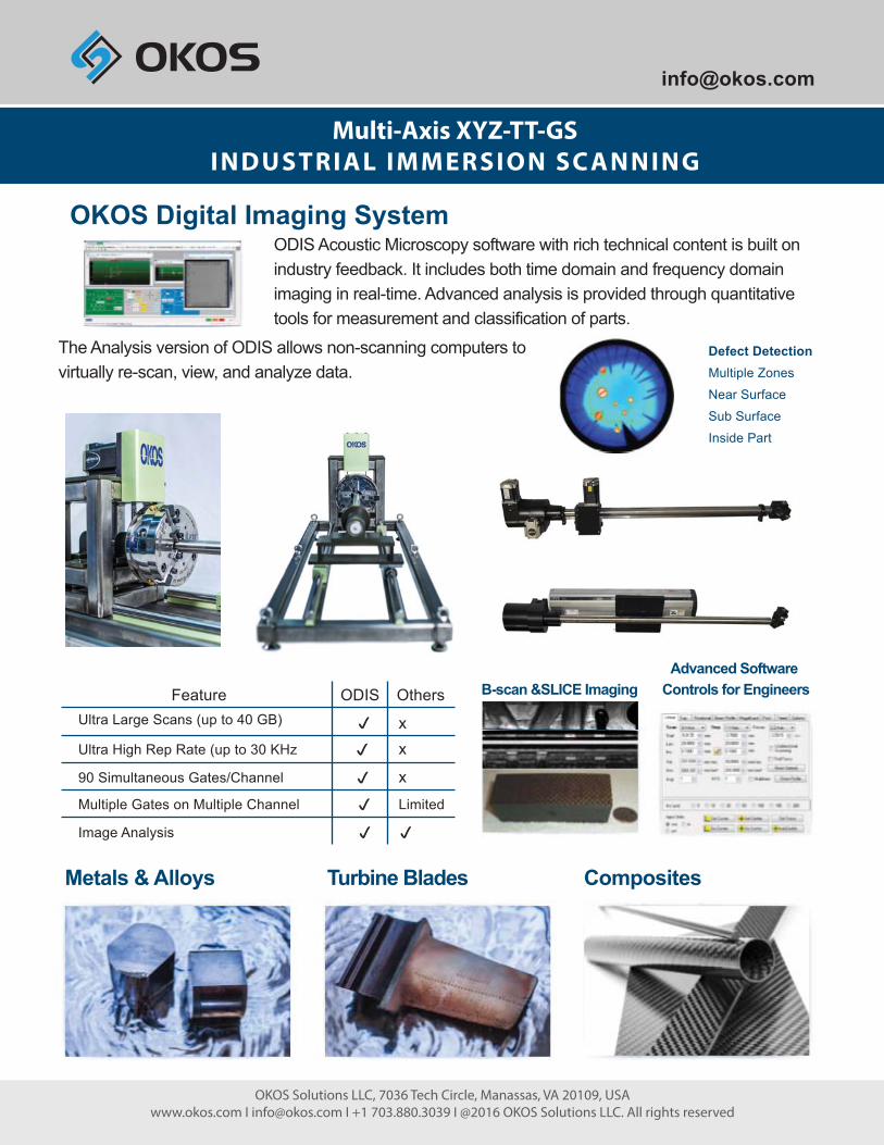
ODIS Acoustic Microscopy software with rich technical content is built on industry feedback. It includes both time domain and frequency domain imaging in real-time. Advanced analysis is provided through quantitative tools for measurement and classification of parts.
The Analysis version of ODIS allows non-scanning computers to virtually re-scan, view, and analyze data.
OKOS Digital Imaging System
Defect DetectionMultiple ZonesNear SurfaceSub SurfaceInside Part
Ultra Large Scans (up to 40 GB)
Image Analysis
Feature ODIS Others
xx
xLimitedMultiple Gates on Multiple Channel
90 Simultaneous Gates/Channel
Ultra High Rep Rate (up to 30 KHz
Metals & Alloys Turbine Blades
Advanced Software Controls for EngineersB-scan &SLICE Imaging
Multi-Axis XYZ-TT-GSINDUSTRIAL IMMERSION SC ANNING

Defect Detection. Multiple Zones. Near Surface. Sub Surface. Inside Part
. X, Y and Z linear axes
. Scan Envelope 300 mm x 300 mm x 150 mm
. Optional Turntable
. Optional Through Transmission Yoke
. Optional Gimbal
. 360 Degree view acrylic tank
. Optional linear servo on X axis
. 12-bit dynamic range instrumentation
. High gain Pulser/Receiver
. Hardware TGC/DAC control
. Application-specific transducers
. Full-featured NDT scanning software
. Off-line Analysis
Gimbal Turntable
Ultrasonic NDT Inspection of
. Hard-cutting materials
. Composites
. Custom alloys
. Solder joints
. Plastics
. Printed circuit boards
. Turbine blades
NDT-CF 300Multi Axes NDT Scanner Compact Footprint
Composites Metals and Alloys Turbine blades
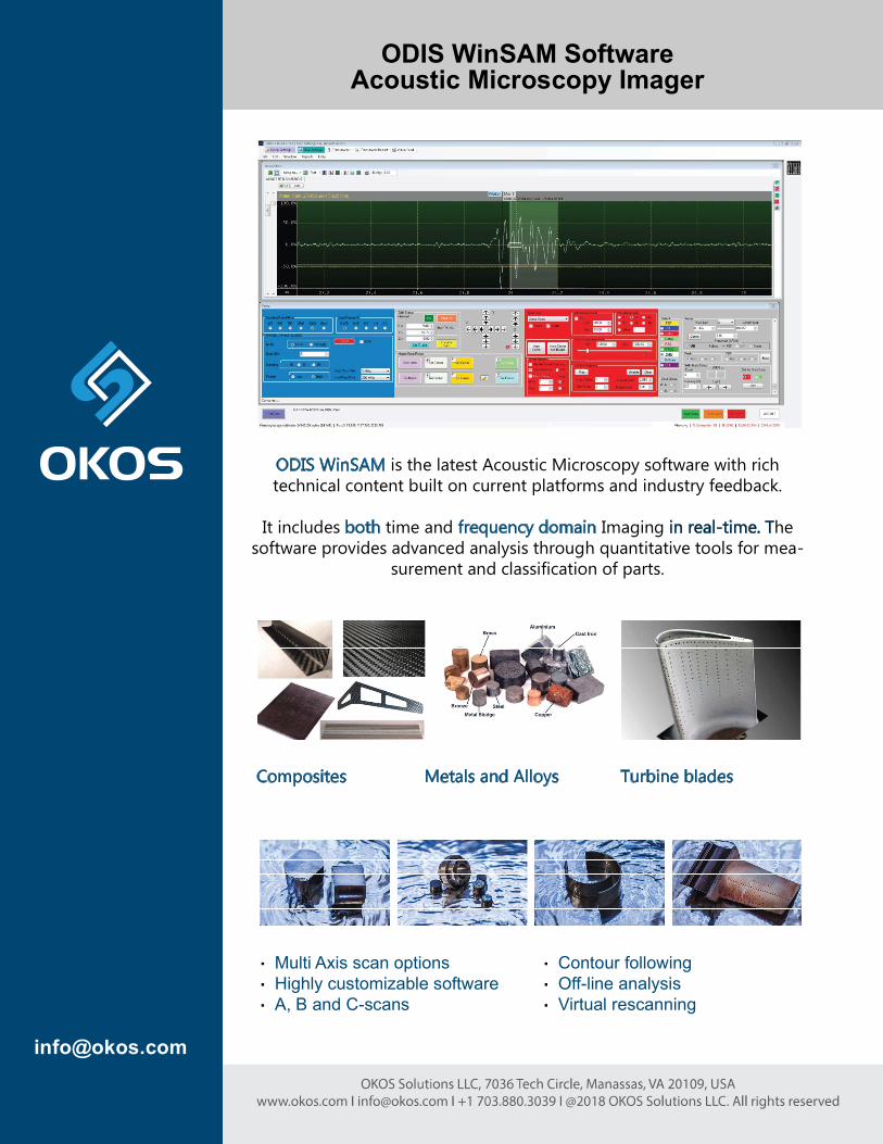
ODIS WinSAM SoftwareAcoustic Microscopy Imager
ODIS WinSAM is the latest Acoustic Microscopy software with richtechnical content built on current platforms and industry feedback.
It includes both time and frequency domain Imaging in real-time. The software provides advanced analysis through quantitative tools for mea-
surement and classification of parts.
. Multi Axis scan options
. Highly customizable software
. A, B and C-scans
. Contour following
. Off-line analysis
. Virtual rescanning

Included Software Modes:
Basic (user friendly)
Advanced (detailed analysis)
Offline Analysis (virtual scanning)
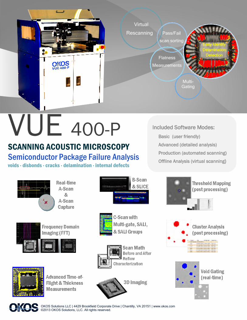
Semiconductor Package Failure Analysis
VUE 250-P
Easy Identify Delamination
Detection
Virtual Rescanning
Multi-
Gating
Thickness
Measurements
SCANNING ACOUSTIC MICROSCOPY
Semiconductor Package Failure Analysis voids · disbonds · cracks · delamination · internal defects
3D Imaging
Scan Math Before and After
Reflow
Characterization
C-Scan with
Multi-gate, SALI,
& SALI Groups
B-Scan
& SLICE Threshold Mapping
(post processing)
Cluster Analysis
(post processing)
Void Gating
(real-time)
Real-time
A-Scan
&
A-Scan
Capture
Frequency Domain
Imaging (FFT)
Advanced Time-of-
Flight & Thickness
Measurements
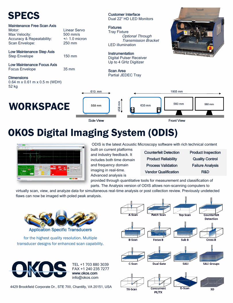
Customer Interface Dual 22” HD LED Monitors Fixtures Tray Fixture Optional Through Transmission Bracket LED illumination Instrumentation Digital Pulser Receiver Up to 4 GHz Digitizer Scan Area Partial JEDEC Tray
Maintenance Free Scan Axis Motor: Linear Servo Max Velocity: 500 mm/s Accuracy & Repeatability: +/- 1.0 micron Scan Envelope: 250 mm Low Maintenance Step Axis Step Envelope 150 mm Low Maintenance Focus Axis Focus Envelope 35 mm Dimensions 0.64 m x 0.61 m x 0.5 m (WDH) 52 kg
ODIS is the latest Acoustic Microscopy software with rich technical content
built on current platforms
and industry feedback. It
includes both time domain
and frequency domain
imaging in real-time.
Advanced analysis is
provided through quantitative tools for measurement and classification of
parts. The Analysis version of ODIS allows non-scanning computers to
virtually scan, view, and analyze data for simultaneous real-time analysis or post collection review. Previously undetected
flaws can now be imaged with poled peak analysis.
Counterfeit Detection
Product Reliability
Process Validation
Vendor Qualification
Product Inspection
Quality Control
Failure Analysis
R&D
OKOS Digital Imaging System (ODIS)
WORKSPACE
SPECS
TEL +1 703 880 3039 FAX +1 240 235 7277 www.okos.com [email protected]
4429 Brookfield Corporate Dr., STE 700, Chantilly, VA 20151, USA
Application Specific Transducers
for the highest quality resolution. Multiple
transducer designs for enhanced scan capability.
Easy Identify
Delamination
Detection
Virtual
Rescanning Pass/Fail
scan sorting
Multi- Gating
Flatness
Measurements
Included Software Modes:
Basic (user friendly)
Advanced (detailed analysis)
Production (automated scanning)
Offline Analysis (virtual scanning)
Semiconductor Package Failure Analysis
VUE 400-P SCANNING ACOUSTIC MICROSCOPY
Semiconductor Package Failure Analysis voids · disbonds · cracks · delamination · internal defects
OKOS Solutions LLC | 4429 Brookfield Corporate Drive | Chantilly, VA 20151 | www.okos.com ©2013 OKOS Solutions, LLC. All rights reserved.

Customer Interface Dual 22” HD LED Monitors Fixtures Tray Fixture Optional Through Transmission Bracket LED illumination Instrumentation Digital Pulser Receiver Optional second channel Up to 12 GHz Digitizer Scan Area Dual JEDEC Trays Up to 300 mm wafer
Maintenance Free Scan Axis Motor: Quad Linear Servo Max Velocity: 1500 mm/s Accuracy & Repeatability: +/- 0.5 micron Scan Envelope: 380 mm Low Maintenance Step Axis Step Envelope 350 mm Low Maintenance Focus Axis Focus Envelope 50 mm Dimensions 0.9 m x 0.86 m x 1.18 m (WDH) 227 kg
OKOS Digital Imaging System (ODIS)
SPECS
VUE 400-P imaging power surpasses modern standards
delivering premium FA Lab features to semiconductor
fabrication facilities. ODIS is the latest Acoustic Microscopy software
with rich technical content
built on current platforms and
industry feedback. It includes
both time domain and frequency domain imaging in real-time.
Advanced analysis is provided through quantitative tools for measurement and classification of parts. The Analysis version
of ODIS allows non-scanning computers to virtually scan, view, and analyze data for simultaneous real-time analysis or
post collection review. Previously undetected flaws can now be imaged with poled peak analysis. Supplied with your
choice of Windows 7 or 8.
TEL +1 703 880 3039 FAX +1 240 235 7277 www.okos.com [email protected]
4429 Brookfield Corporate Dr., STE 700, Chantilly, VA 20151, USA
Counterfeit Detection
Product Reliability
Process Validation
Vendor Qualification
Product Inspection
Quality Control
Failure Analysis
R&D
Clean
Room
Ready
Application Specific Transducers for the highest quality resolution. Multiple
transducer designs for enhanced scan capability.
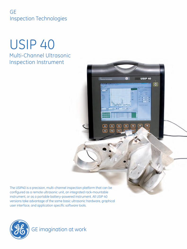
USIP 40Multi-Channel UltrasonicInspection Instrument
The USIP40 is a precision, multi-channel inspection platform that can be configured as a remote ultrasonic unit, an integrated rack-mountable instrument, or as a portable battery-powered instrument. All USIP 40 versions take advantage of the same basic ultrasonic hardware, graphical user interface, and application specific software tools.
GEInspection Technologies
The Ultimate Inspection Confidence
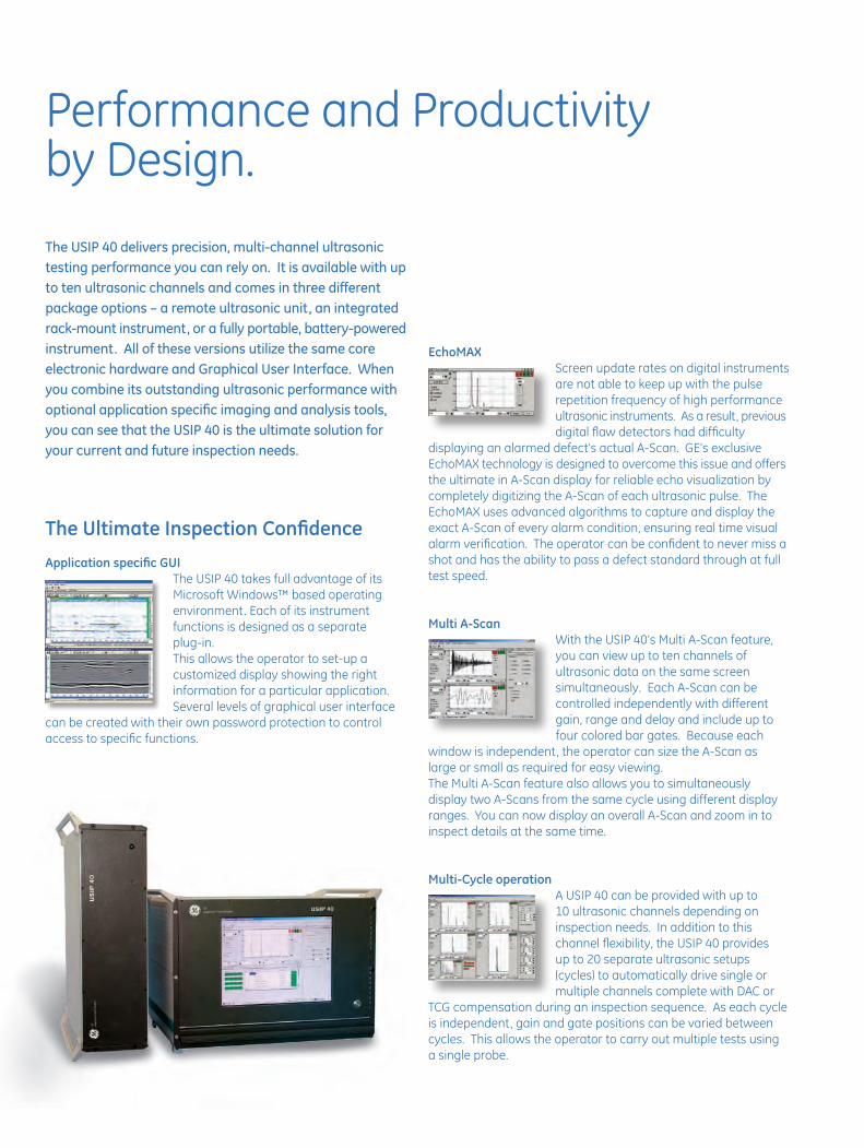
Application specific GUIThe USIP 40 takes full advantage of its Microsoft Windows™ based operating environment. Each of its instrument functions is designed as a separateplug-in. This allows the operator to set-up a customized display showing the right information for a particular application. Several levels of graphical user interface
can be created with their own password protection to control access to specific functions.
Performance and Productivity by Design.
The USIP 40 delivers precision, multi-channel ultrasonic testing performance you can rely on. It is available with up to ten ultrasonic channels and comes in three different package options – a remote ultrasonic unit, an integrated rack-mount instrument, or a fully portable, battery-powered instrument. All of these versions utilize the same core electronic hardware and Graphical User Interface. When you combine its outstanding ultrasonic performance with optional application specific imaging and analysis tools, you can see that the USIP 40 is the ultimate solution for your current and future inspection needs.
EchoMAXScreen update rates on digital instruments are not able to keep up with the pulse repetition frequency of high performance ultrasonic instruments. As a result, previous digital flaw detectors had difficulty
displaying an alarmed defect’s actual A-Scan. GE’s exclusive EchoMAX technology is designed to overcome this issue and offers the ultimate in A-Scan display for reliable echo visualization by completely digitizing the A-Scan of each ultrasonic pulse. The EchoMAX uses advanced algorithms to capture and display the exact A-Scan of every alarm condition, ensuring real time visual alarm verification. The operator can be confident to never miss a shot and has the ability to pass a defect standard through at full test speed.
Multi A-Scan With the USIP 40’s Multi A-Scan feature, you can view up to ten channels of ultrasonic data on the same screen simultaneously. Each A-Scan can be controlled independently with different gain, range and delay and include up to four colored bar gates. Because each
window is independent, the operator can size the A-Scan as large or small as required for easy viewing.The Multi A-Scan feature also allows you to simultaneously display two A-Scans from the same cycle using different display ranges. You can now display an overall A-Scan and zoom in to inspect details at the same time.
Multi-Cycle operation A USIP 40 can be provided with up to 10 ultrasonic channels depending on inspection needs. In addition to this channel flexibility, the USIP 40 provides up to 20 separate ultrasonic setups (cycles) to automatically drive single or multiple channels complete with DAC or
TCG compensation during an inspection sequence. As each cycle is independent, gain and gate positions can be varied between cycles. This allows the operator to carry out multiple tests using a single probe.

Feature Summary
• Up to 10 ultrasonic channels
• Up to 20 kHz PRF
• Aero version qualified to GE and RRAE specifications
• Independent pulser and receiver for each channel
• 20 Programmable cycles for multi-zone inspection
• EchoMAX A-Scan display function
• View up to 10 A-Scans at once
• Available strip chart , C-Scan imaging, and TOFD weld inspection software
• Interface gate synchronizing for surface following
• Back-wall echo attenuator
• Direct 3-axis encoder input
• Automatic Gain Control
• User configurable in English, French, German, Spanish, Japanese, Chinese
Wide Fields of Application
AerospaceThe USIP 40 Aero configuration is qualified to GE DFO P3TF22, P3TF30, P3TF35, and RRAE RPS705 specifications for jet engine component inspections. USIP 40 instruments are also extensively used for airframe composite inspection by leading aircraft manufacturers.
AutomotiveUsed in conjunction with Ultraproof imaging software, the USIP 40 is the perfect instrument for inspecting pistons and other safety critical parts. Configured in this way, the USIP 40 provides visualization and recording of alarm outputs as well as automatic evaluation and reporting of single flaws, interacted flaws, and total numbers of flaws per part and per batch.
Pipe and tubeWith the appropriate probe holders and imaging software, the USIP 40 is easily set up for weld inspection, multi-channel flaw detection and wall thickness measurement.
Plate and billet Combining inspection productivity and coverage requires multiple inspection channels. The 10-Channel USIP 40 fills this need in both manual and automated inspection environments.
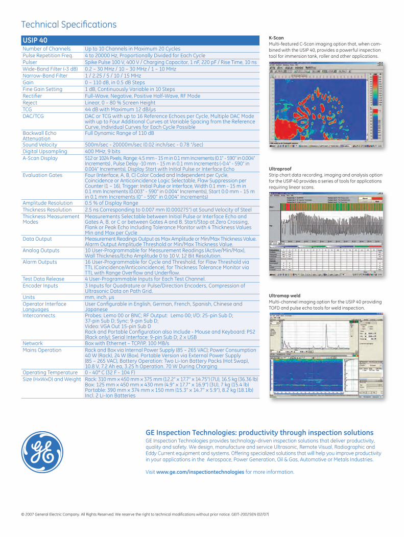
Roll testing The multi-channel USIP 40 combined with C-Scan imaging provides rapid scanning of industrial rollers. GE’s K-Scan software knits multiple ultrasonic channels to form one continuous C-Scan. In combination with the USIP 40’s 20,000 Hz PRF, this package is perfect for high-speed defect evaluation and sizing.
Vessel weld inspection Combined with Ultramap Weld software, the USIP 40 can be configured to perform multi-channel inspections of welds on pressure vessels to ASME Case 2235 utilizing both Time of Flight Diffraction (TOFD) and pulse-echo B-Scan imaging and data archiving tools.
© 2007 General Electric Company. All Rights Reserved. We reserve the right to technical modifications without prior notice. GEIT-20025EN (02/07)
K-Scan Multi-featured C-Scan imaging option that, when com-bined with the USIP 40, provides a powerful inspection tool for immersion tank, roller and other applications.
USIP 40Number of Channels Up to 10 Channels in Maximum 20 CyclesPulse Repetition Freq. 4 to 20000 Hz, Proportionally Divided for Each CyclePulser Spike Pulse 100 V, 400 V / Charging Capacitor, 1 nF, 220 pF / Rise Time, 10 nsWide-Band Filter (-3 dB) 0.2 – 30 MHz / 10 – 30 MHz / 1 – 10 MHzNarrow-Band Filter 1 / 2.25 / 5 / 10 / 15 MHzGain 0 – 110 dB, in 0.5 dB StepsFine Gain Setting 1 dB, Continuously Variable in 10 StepsRectifier Full-Wave, Negative, Positive Half-Wave, RF ModeReject Linear, 0 – 80 % Screen HeightTCG 44 dB with Maximum 12 dB/μsDAC/TCG DAC or TCG with up to 16 Reference Echoes per Cycle, Multiple DAC Mode
with up to Four Additional Curves at Variable Spacing from the Reference Curve, Individual Curves for Each Cycle Possible
Backwall Echo Attenuation
Full Dynamic Range of 110 dB
Sound Velocity 500m/sec - 20000m/sec (0.02 inch/sec - 0.78 “/sec)Digital Upsampling 400 MHz, 9 bitsA-Scan Display 512 or 1024 Pixels, Range: 4.5 mm - 15 m in 0.1 mm Increments (0.1“ - 590“ in 0.004“
Increments) , Pulse Delay -10 mm - 15 m in 0.1 mm Increments (-0.4” - 590“ in 0.004“ Increments), Display Start with Initial Pulse or Interface Echo
Evaluation Gates Four (Interface, A, B, C) Color Coded and Independent per Cycle, Coincidence or Anticoincidence Logic Selectable, Flaw Suppression per Counter (1 – 16), Trigger: Initial Pulse or Interface, Width 0.1 mm - 15 m in 0.1 mm Increments (0.003” - 590” in 0.004” Increments), Start 0.0 mm - 15 m in 0.1 mm Increments (0” - 590” in 0.004” Increments)
Amplitude Resolution 0.5 % of Display RangeThickness Resolution 2.5 ns Corresponding to 0.007 mm (0.000275”) at Sound Velocity of SteelThickness Measurement Modes
Measurements Selectable between Initial Pulse or Interface Echo and Gates A, B, or C or between Gates A and B. Start/Stop at Zero Crossing, Flank or Peak Echo Including Tolerance Monitor with 4 Thickness Values Min and Max per Cycle
Data Output Measurement Readings Output as Max Amplitude or Min/Max Thickness Value.Alarm Output Amplitude Threshold or Min/Max Thickness Value.
Analog Outputs 10 User-Programmable for Measurement Readings (Active/Min/Max), Wall Thickness/Echo Amplitude 0 to 10 V, 12 Bit Resolution.
Alarm Outputs 16 User-Programmable for Cycle and Threshold, for Flaw Threshold via TTL (Coincidence/Anticoincidence), for Thickness Tolerance Monitor via TTL with Range Overflow and Underflow.
Test Data Release 4 User-Programmable Inputs for Each Test Channel.Encoder Inputs 3 Inputs for Quadrature or Pulse/Direction Encoders, Compression of
Ultrasonic Data on Path Grid.Units mm, inch, μsOperator Interface Languages
User Configurable in English, German, French, Spanish, Chinese and Japanese
Interconnects Probes: Lemo 00 or BNC; RF Output: Lemo 00; I/O: 25-pin Sub D; 37-pin Sub D; Sync: 9-pin Sub D;Video: VGA Out 15-pin Sub DRack and Portable Configuration also Include - Mouse and Keyboard: PS2 (Rack only); Serial Interface: 9-pin Sub D; 2 x USB
Network Box with Ethernet – TCP/IP, 100 MB/sMains Operation Rack and Box via Internal Power Supply (85 – 265 VAC); Power Consumption
40 W (Rack), 24 W (Box). Portable Version via External Power Supply (85 – 265 VAC), Battery Operation: Two Li-Ion Battery Packs (Hot Swap), 10.8 V, 7.2 Ah ea, 3.25 h Operation. 70 W During Charging
Operating Temperature 0 - 40° C (32 F - 104 F)Size (HxWxD) and Weight Rack: 310 mm x 450 mm x 375 mm (12.2” x 17.7” x 14.75”) (7U), 16.5 kg (36.36 lb)
Box: 125 mm x 450 mm x 430 mm (4.9” x 17.7” x 16.9”) (3U), 7 kg (15.4 lb)Portable: 390 mm x 374 mm x 150 mm (15.3” x 14.7” x 5.9”), 8.2 kg (18.1lb) Incl. 2 Li-Ion Batteries
Technical Specifications
Ultramap weld Multi-channel imaging option for the USIP 40 providing TOFD and pulse echo tools for weld inspection.
Ultraproof Strip chart data recording, imaging and analysis option for the USIP 40 provides a series of tools for applications requiring linear scans.
GE Inspection Technologies: productivity through inspection solutions GE Inspection Technologies provides technology-driven inspection solutions that deliver productivity, quality and safety. We design, manufacture and service Ultrasonic, Remote Visual, Radiographic and Eddy Current equipment and systems. Offering specialized solutions that will help you improve productivity in your applications in the Aerospace, Power Generation, Oil & Gas, Automotive or Metals Industries. Visit www.ge.com/inspectiontechnologies for more information.