multi-angle spectrophotometer - x-rite · this equipment generates, uses, and can radiate radio ......
TRANSCRIPT

Multi-Angle Spectrophotometer (Covers models: MA94, MA96, and MA98)
User Guide


M U L T I - A N G L E S P E C T R O P H O T O M E T E R
1
CE Declaration Hereby, X-Rite, Incorporated, declares that this MA9X Series is in compliance with the essential requirements and other relevant provisions of Directive(s) 2014/35/EU (LVD), 2014/30/EU (EMC), and RoHS 2011/65/EU.
Bluetooth equipped devices additional comply with Directive RED 2014/53/EU.
Federal Communications Commission Notice NOTE: This equipment has been tested and found to comply with the limits for a Class A digital device, pursuant to Part 15 of the FCC Rules. These limits are designed to provide reasonable protection against harmful interference when the equipment is operated in a commercial environment. This equipment generates, uses, and can radiate radio frequency energy and, if not installed and used in accordance with the instruction manual, may cause harmful interference to radio communications. Operation of this equipment in a residential area is likely to cause harmful interference in which case the user will be required to correct the interference at his own expense.
Industry Canada Compliance Statement This Class A digital apparatus complies with Canadian ICES-003.
Cet appareil numérique de la classe A est conforme à la norme NMB-003 du Canada.
Equipment Information Use of this equipment in a manner other than that specified by X-Rite, Incorporated may compromise design integrity and become unsafe. WARNING: This instrument is not for use in explosive environments. Transportation: This product contains a lithium-ion battery. Should you need to ship this device, you may wish to consult published guidance documents by one or more of these organizations for advice on how to comply with the regulations: IATA, ICOA, IMDG & PHMSA. The battery contained in the MA9X series device is 107g in weight, 7.4V, 2.4 Ah, and complies with the UN 38.3 tests in effect the year it was originally shipped. Instructions for disposal: Please dispose of Waste Electrical and Electronic Equipment (WEEE) at designated collection points for the recycling of such equipment.

M U L T I - A N G L E S P E C T R O P H O T O M E T E R
2
If your device is equipped with a Bluetooth wireless transmitter, it contains the following module.
Microchip RN42 Microchip Technology Inc.
2355 West Chandler Blvd.
Chandler, Arizona 85224
TEL: 480-792-7200
Module meets the following standards:
EN 300328 V1.8.1 (2012)
EN 301489-1 V1.9.2 (2011)
EN 301489-17 V2.2.1 (2012)
EN 60950-1:2006 ITE General Requirement
EN 62479 (2010)+A11:2009+A1:2010+A12:2011
FCC RF Radiation Exposure Statement:
This device complies with FCC radiation exposure limits set forth for an uncontrolled environment. End users must follow the specific operating instructions for satisfying RF exposure compliance. This transmitter must not be co-located or operating in conjunction with any other antenna or transmitter.
Contains Microchip RN42 module:
FCC-ID: T9JRN42 IC: T9JRN42

M U L T I - A N G L E S P E C T R O P H O T O M E T E R
3
Proprietary Notice The information contained in this manual is copyrighted information proprietary to X-Rite, Incorporated.
Publication of this information does not imply any rights to reproduce or use it for purposes other than installing, operating, or maintaining this instrument described herein. No part of this manual may be reproduced, transcribed or translated into any language or computer language in any form or by any means: electronic, magnetic, mechanical, optical, manual, or otherwise; without the prior written permission of an authorized officer of X-Rite, Incorporated.
Patents: www.xrite.com/ip
“© 2018, X-Rite, Incorporated. All rights reserved”
X-Rite® is a registered trademark of X-Rite, Incorporated. All other logos, brand names, and product names mentioned are the properties of their respective holders.
Warranty Information X-Rite warrants this Product against defects in material and workmanship for a period of twelve (12) months from the date of shipment from X-Rite’s facility, unless mandatory law provides for longer periods. During such time, X-Rite will either replace or repair at its discretion defective parts free of charge.
X-Rite’s warranties herein do not cover failure of warranted goods resulting from: (i) damage after shipment, accident, abuse, misuse, neglect, alteration or any other use not in accordance with X-Rite’s recommendations, accompanying documentation, published specifications, and standard industry practice; (ii) using the device in an operating environment outside the recommended specifications or failure to follow the maintenance procedures in X-Rite’s accompanying documentation or published specifications; (iii) repair or service by anyone other than X-Rite or its authorized representatives; (iv) the failure of the warranted goods caused by use of any parts or consumables not manufactured, distributed, or approved by X-Rite; (v) any attachments or modifications to the warranted goods that are not manufactured, distributed or approved by X-Rite. Consumable parts and Product cleaning are also not covered by the warranty.
X-Rite‘s sole and exclusive obligation for breach of the above warranties shall be the repair or replacement of any part, without charge, which within the warranty period is proven to X-Rite‘s reasonable satisfaction to have been defective. Repairs or replacement by X-Rite shall not revive an otherwise expired warranty, nor shall the same extend the duration of a warranty.
Customer shall be responsible for packaging and shipping the defective product to the service center designated by X-Rite. X-Rite shall pay for the return of the product to Customer if the shipment is to a location within the region in which the X-Rite service center is located. Customer shall be responsible for paying all shipping charges, duties, taxes, and any other charges for products returned to any other locations. Proof of purchase in the form of a bill of sale or receipted invoice which is evidence that the unit is within the Warranty period must be presented to obtain warranty service. Do not try to dismantle the Product. Unauthorized dismantling of the equipment will void all warranty claims. Contact the X-Rite Support or the nearest X-Rite Service Center, if you believe that the unit does not work anymore or does not work correctly.
THESE WARRANTIES ARE GIVEN SOLELY TO BUYER AND ARE IN LIEU OF ALL OTHER WARRANTIES, EXPRESSED OR IMPLIED, INCLUDING BUT NOT LIMITED TO THE IMPLIED
M U L T I - A N G L E S P E C T R O P H O T O M E T E R
4
WARRANTIES OF MERCHANTABILITY, FITNESS FOR A PARTICULAR PURPOSE OR APPLICATION, AND NON-INFRINGEMENT. NO EMPLOYEE OR AGENT OF X-RITE, OTHER THAN AN OFFICER OF X-RITE, IS AUTHORIZED TO MAKE ANY WARRANTY IN ADDITION TO THE FOREGOING.
IN NO EVENT WILL X-RITE BE LIABLE FOR ANY OF BUYER’S MANUFACTURING COSTS, OVERHEAD, LOST PROFITS, GOODWILL, OTHER EXPENSES OR ANY INDIRECT, SPECIAL, INCIDENTAL OR CONSEQUENTIAL DAMAGES BASED UPON BREACH OF ANY WARRANTY, BREACH OF CONTRACT, NEGLIGENCE, STRICT TORT, OR ANY OTHER LEGAL THEORY. IN ANY EVENT OF LIABILITY, X-RITE’S MAXIMUM LIABILITY HEREUNDER WILL NOT EXCEED THE PRICE OF THE GOODS OR SERVICES FURNISHED BY X-RITE GIVING RISE TO THE CLAIM.
M U L T I - A N G L E S P E C T R O P H O T O M E T E R
5
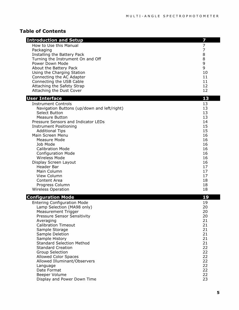
Table of Contents
Introduction and Setup 7 How to Use this Manual 7 Packaging 7 Installing the Battery Pack 8 Turning the Instrument On and Off 8 Power Down Mode 9 About the Battery Pack 9 Using the Charging Station 10 Connecting the AC Adapter 11 Connecting the USB Cable 11 Attaching the Safety Strap 12 Attaching the Dust Cover 12
User Interface 13 Instrument Controls 13
Navigation Buttons (up/down and left/right) 13 Select Button 13 Measure Button 13
Pressure Sensors and Indicator LEDs 14 Instrument Positioning 15
Additional Tips 15 Main Screen Menu 16
Measure Mode 16 Job Mode 16 Calibration Mode 16 Configuration Mode 16 Wireless Mode 16
Display Screen Layout 16 Header Bar 17 Main Column 17 View Column 17 Content Area 18 Progress Column 18
Wireless Operation 18
Configuration Mode 19 Entering Configuration Mode 19
Lamp Selection (MA98 only) 20 Measurement Trigger 20 Pressure Sensor Sensitivity 20 Averaging 21 Calibration Timeout 21 Sample Storage 21 Sample Deletion 21 Sample History 21 Standard Selection Method 21 Standard Creation 22 Group Selection 22 Allowed Color Spaces 22 Allowed Illuminant/Observers 22 Language 22 Date Format 22 Beeper Volume 22 Display and Power Down Time 23

M U L T I - A N G L E S P E C T R O P H O T O M E T E R
6
Instrument Orientation 23 Clear All Samples 23 Load Defaults 23
Calibration Mode 24 Positioning the Instrument on the Black Trap 24 Positioning the Instrument on the Calibration Reference 25 Calibrating the Instrument 25
Measure Mode 27 Entering Measure Mode 27 Measure Mode Icons 27 Selecting a Group 28 Manually Selecting a Standard 29 Selecting a Color Space 30 Selecting Illuminant/Observer Combinations 31 Measuring a Sample 32 Using Measurement Averaging 33 Using Graph View 34 Viewing Stored Measurements 35 Viewing Pass/Fail Data 35
∆L*a*b* Color Space (pass/fail) 35 ∆L*a*b* Color Space (pass/warning) 36 Pass/Fail Option 36
Using Quick Compare 37 Creating Standards 38
Job Mode 39 Accessing Job Mode 39 Job Mode Icons 39 Selecting and Running a Job 40
Appendices 42 Service Information 42 Cleaning the Instrument 43
General Cleaning 43 Cleaning the Optics 43 Cleaning the Calibration Reference 43 Cleaning the Black Trap 44
Replacing the Battery Pack 44 Troubleshooting 45 Screen Messages 46 Resetting the Instrument 46 Instrument Specifications 47

M U L T I - A N G L E S P E C T R O P H O T O M E T E R
7
INTRODUCTION AND SETUP
The multi-angle spectrophotometer is designed for consistent, precise color measurement of metallic, pearlescent, and other complex special effect finishes. The MA98 provides 10 measurement angles and 2 illumination angles to create a unique master profile of each color that serves as a benchmark for optimizing color communication from initial design, through formulation, processing, and quality assurance.
Key features of the instrument are:
• Hi-resolution 240 x 320, 18-bit color display
• Controls that include navigation buttons for easy screen selections, measure button, and power on/off.
• Three pressure sensors located on the bottom of the instrument to aid in proper positioning.
How to Use this Manual This manual is intended to provide setup, operation and general maintenance of the instrument. Specific software application information is available in the software help system.
Packaging Your instrument packaging should contain all the items listed below. If any of these items are missing or damaged, contact X-Rite or your Authorized Representative.
• Multi-angle instrument • Carrying case • USB interface cabling • AC adapter (X-Rite P/N SE30-277)
and line cord • Calibration reference • Black trap
LCD color display
USB input
Measure button
AC adapter input
Dust cover
Select button and navigation buttons (up, down, left, and right)
On/off power button
Positioning LEDs (3)
• 2 Li-ion rechargeable battery packs • Charging station • Safety strap • Dust cover • Manuals CD • Documentation and registration material
Safety strap connection
M U L T I - A N G L E S P E C T R O P H O T O M E T E R
8
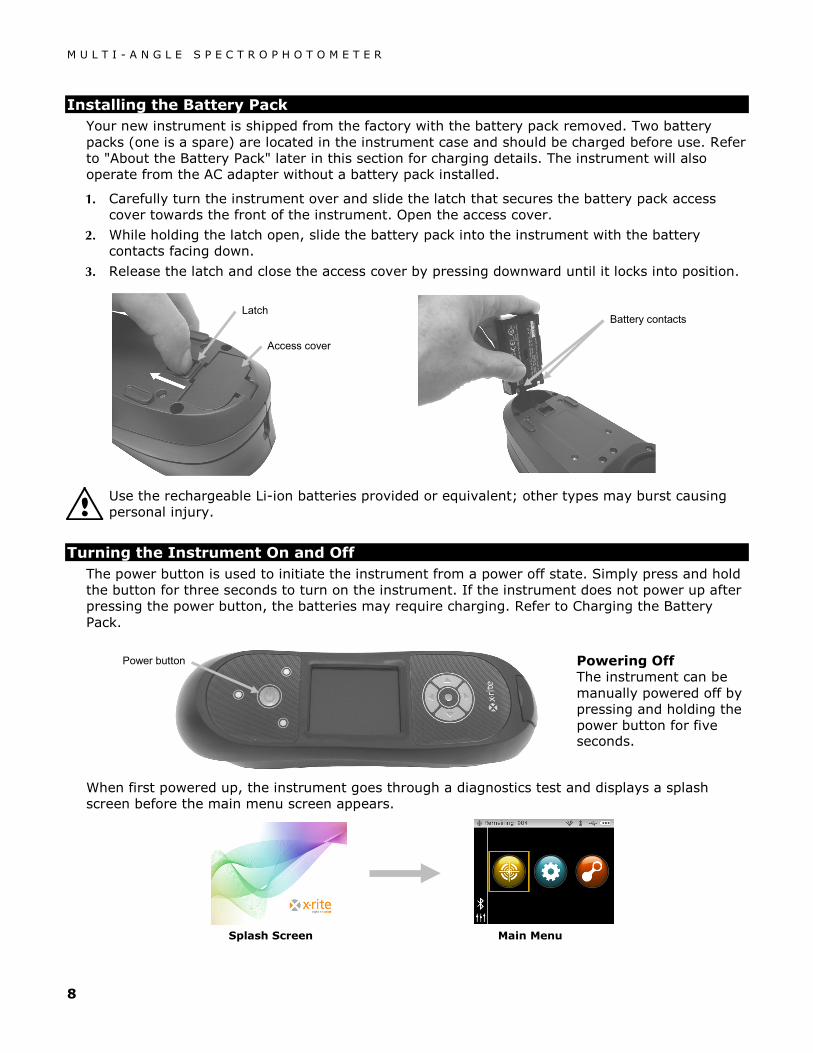
Installing the Battery Pack
Your new instrument is shipped from the factory with the battery pack removed. Two battery packs (one is a spare) are located in the instrument case and should be charged before use. Refer to "About the Battery Pack" later in this section for charging details. The instrument will also operate from the AC adapter without a battery pack installed.
1. Carefully turn the instrument over and slide the latch that secures the battery pack access cover towards the front of the instrument. Open the access cover.
2. While holding the latch open, slide the battery pack into the instrument with the battery contacts facing down.
3. Release the latch and close the access cover by pressing downward until it locks into position.
Use the rechargeable Li-ion batteries provided or equivalent; other types may burst causing personal injury.
Turning the Instrument On and Off The power button is used to initiate the instrument from a power off state. Simply press and hold the button for three seconds to turn on the instrument. If the instrument does not power up after pressing the power button, the batteries may require charging. Refer to Charging the Battery Pack.
When first powered up, the instrument goes through a diagnostics test and displays a splash screen before the main menu screen appears.
Splash Screen Main Menu
Access cover
Latch Battery contacts
Power button Powering Off The instrument can be manually powered off by pressing and holding the power button for five seconds.

M U L T I - A N G L E S P E C T R O P H O T O M E T E R
9
Power Down Mode The instrument utilizes two power down modes to conserve battery life during nonuse times. The power down mode is preset in the Configuration Mode.
Standby Mode - The instrument is ready to measure, however the display is not on. A button press, measurement, power connection (if not connected), or USB connection will wake up the instrument. Standby mode does not occur when the AC adapter is attached to the instrument.
Off Mode - The power button must be pressed and held for three seconds to wake up the instrument before a measurement can be taken. Plugging in the AC adapter will also wake up the instrument from power off mode. Off mode does not occur when the AC adapter is attached to the instrument.
About the Battery Pack
General
The battery packs for your new instrument come in a low to medium charge state and should be charged before use (up to 4 hours for full charge).
A charged battery pack may eventually lose partial charge if not used for an extended amount of time. You should charge the battery from time to time and store in a cool environment when not in use to maintain battery performance.
The battery pack can be charged in the instrument (see Connecting the AC Adapter) or by use of the charging station. The charging station is useful for charging up to two battery packs.
Lifespan Expectations
Lithium-ion batteries typically decay to 80% capacity after 400 charge cycles (see chart below). A charge cycle can be defined as several partial charges equaling 100%. Partial charge and discharge cycles will help maintain the life of the battery. It is best to avoid full discharge and charge cycles. After roughly 400 charge cycles are reached, the amount of measurements you can expect to achieve from one full charge is reduced. At this point, you may wish to replace the battery pack.
Disposal
Dispose of the battery pack in a designated disposal location for recycling.
Cycle Life Characteristics
Cycles
1.0 C Discharge C/2 Discharge
1.25 A CC/CV Charge, 4.2 V, 3 hrs.
Capa
city (
Ah)

M U L T I - A N G L E S P E C T R O P H O T O M E T E R
10
Using the Charging Station
The charging station has a separate indicator LED for each charging position. The LEDs illuminate “red” when a battery pack is charging, amber when battery pack is close to a full charge, and “green” when no battery is inserted or after the battery is fully charged. A battery pack takes approx. 4 hours to reach a full charge from a completely discharged state.
1. Insert the small plug from the AC adapter into the input on the side of the charging station.
2. Plug the detachable line cord into the AC adapter and plug the line cord into the wall receptacle.
3. Position a battery pack over one of the charging locations with the locking tabs in the station directly below the slots in the battery. Make sure the arrow on the top of the battery pack is facing the LED end of the station.
4. Lower the battery pack into position and slide it toward the LED until it stops. Depending on the battery packs current charge state, the LED will illuminate "red", "amber", or "green" when properly seated.
5. After charging is complete, slide the battery in the opposite direction of the LED until it stops and lift upward to remove.
AC adapter input
Battery arrow
LED indicator
LED indicator
Locking tabs
Note: The AC adapter used for the charging station is the same adapter that is used to power the instrument.
M U L T I - A N G L E S P E C T R O P H O T O M E T E R
11
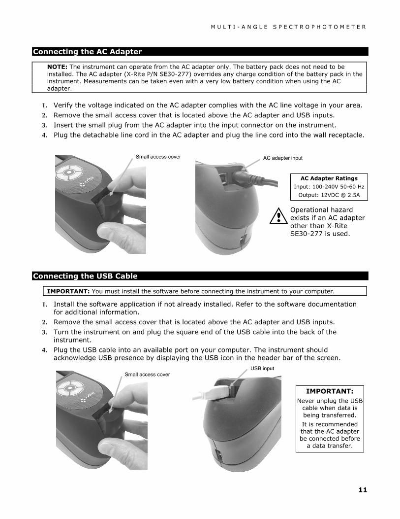
Connecting the AC Adapter
NOTE: The instrument can operate from the AC adapter only. The battery pack does not need to be installed. The AC adapter (X-Rite P/N SE30-277) overrides any charge condition of the battery pack in the instrument. Measurements can be taken even with a very low battery condition when using the AC adapter.
1. Verify the voltage indicated on the AC adapter complies with the AC line voltage in your area.
2. Remove the small access cover that is located above the AC adapter and USB inputs.
3. Insert the small plug from the AC adapter into the input connector on the instrument.
4. Plug the detachable line cord in the AC adapter and plug the line cord into the wall receptacle.
Connecting the USB Cable
IMPORTANT: You must install the software before connecting the instrument to your computer.
1. Install the software application if not already installed. Refer to the software documentation for additional information.
2. Remove the small access cover that is located above the AC adapter and USB inputs.
3. Turn the instrument on and plug the square end of the USB cable into the back of the instrument.
4. Plug the USB cable into an available port on your computer. The instrument should acknowledge USB presence by displaying the USB icon in the header bar of the screen.
AC adapter input
AC Adapter Ratings
Input: 100-240V 50-60 Hz
Output: 12VDC @ 2.5A
IMPORTANT: Never unplug the USB
cable when data is being transferred.
It is recommended that the AC adapter be connected before
a data transfer.
Small access cover
Operational hazard exists if an AC adapter other than X-Rite SE30-277 is used.
USB input
Small access cover
M U L T I - A N G L E S P E C T R O P H O T O M E T E R
12
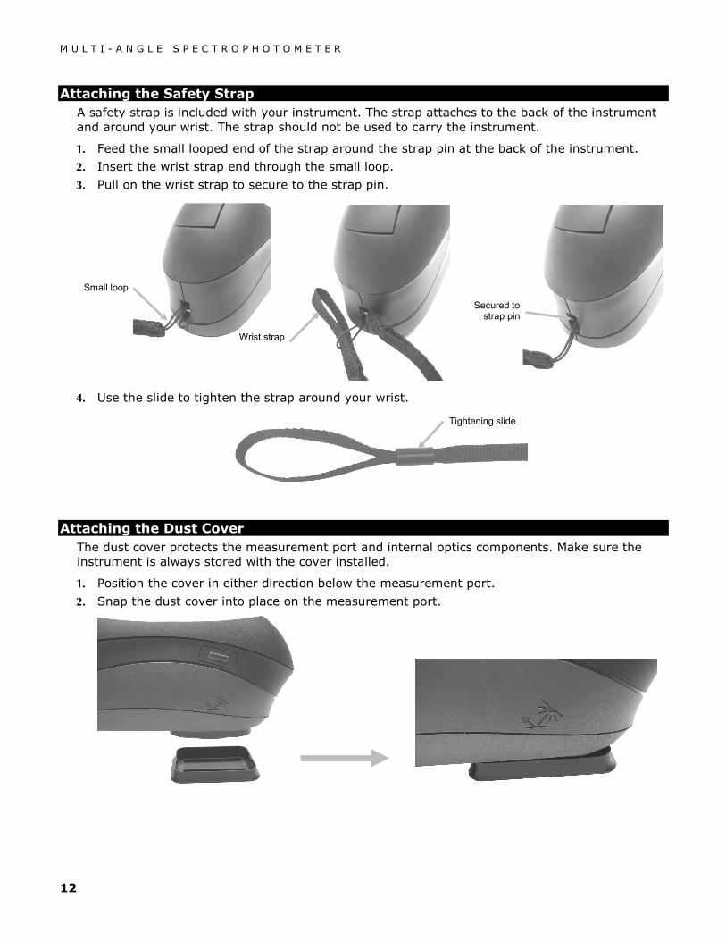
Attaching the Safety Strap
A safety strap is included with your instrument. The strap attaches to the back of the instrument and around your wrist. The strap should not be used to carry the instrument.
1. Feed the small looped end of the strap around the strap pin at the back of the instrument.
2. Insert the wrist strap end through the small loop.
3. Pull on the wrist strap to secure to the strap pin.
4. Use the slide to tighten the strap around your wrist.
Attaching the Dust Cover
The dust cover protects the measurement port and internal optics components. Make sure the instrument is always stored with the cover installed.
1. Position the cover in either direction below the measurement port.
2. Snap the dust cover into place on the measurement port.
Small loop
Wrist strap
Secured to strap pin
Tightening slide

M U L T I - A N G L E S P E C T R O P H O T O M E T E R
13
USER INTERFACE
Instrument Controls The instrument controls are used to navigate the screen, configure options, and perform measurements.
Navigation Buttons (up/down and left/right)
The navigation buttons are used to move the focus of the highlight around the screen. Pressing on the left () button moves the focus to the next available control to the left. Pressing on the right () button moves the focus to the next available control to the right. The up () and down () buttons perform the same function, only in an up and down direction. The navigation buttons change control direction when the instrument screen orientation is changed from right handed operation (default) to left handed operation in the Configuration Mode.
Select Button
The Select button activates the control that has focus, such as a mode or option.
Measure Button
The Measure button is located on the side of the instrument. The button can be configured to initiate a measurement on its own or in conjunction with the pressure sensors. Refer to Configuration mode for additional information on the measure button configuration.
Down button
Right button
Select button
Left button Up button
Measure button

M U L T I - A N G L E S P E C T R O P H O T O M E T E R
14
Pressure Sensors and Indicator LEDs To aid in proper positioning and ensure repeatability of sample measurements, the instrument incorporates three pressure sensors that are integrated into the measurement port. When this option is activated in configuration, an even amount of pressure must be applied across all three sensors before a measurement can occur. The pressure sensor option is typically used when critical instrument positioning is required on a sample.
Positioning feedback is provided by way of three LEDs located on the top of the instrument. The LEDs are arranged in the same pattern as the pressure sensors located in the measurement port. Refer below for LED definitions.
NOTE: The Pressure sensor option must be enabled in Configuration mode.
• LED Off – little or no pressure is being applied to the corresponding sensor.
• LED Amber – not enough force is being applied to the corresponding sensor. You must apply additional pressure to achieve a green LED.
• LED Green – ideal pressure is being applied to the corresponding sensor. A measurement will be taken when all three LEDs illuminate green. If required pressure is not maintained for the duration of the measurement (red or amber LED condition), an error message will appear on the display and the measurement must be retaken.
• LED Red – too much pressure is being applied to the corresponding sensor. Less pressure must be applied to achieve a green LED condition.
Back LED
Back LED
Front LED

M U L T I - A N G L E S P E C T R O P H O T O M E T E R
15
Instrument Positioning In order for the instrument to obtain accurate and repeatable measurements, the bottom of the measurement port must be flat with the sample surface to be measured. Any movement of the instrument can cause the measurement angles to vary, greatly affecting measurements on metallic and pearlescent paint finishes.
Using the pressure sensor feature to activate measurements will ensure measurement data integrity.
The instrument should be held with both hands during a measurement. During a measurement, simply rock the instrument forward until the measurement port is flat on the surface. If the pressure sensor option is activated, apply the correct amount of pressure to the measurement port until all three indicator LEDs turn green.
Additional Tips
• Measurements performed on a surface with a curve can cause measurement errors especially at the near specular angles (±15° and 25°). Measurements should be made on the flattest part of a sample whenever possible. When measuring parts where a flat area is not available, a fixture should be made to repeatedly and accurately position the sample tangent to the measurement plain.
• Hold the instrument firmly by the front and top during a measurement.
• When measuring dark colors or non-uniform samples, several readings should be averaged together for a single measurement. The instrument can be set to average up to five measurements.
The alignment marks located on the left and right sides of the instrument can be used as guides to center the measurement port over the desired sample area. These are useful when precise positioning is required, or if the sample is somewhat small.
Side alignment mark
Measurement port flat on sample

M U L T I - A N G L E S P E C T R O P H O T O M E T E R
16
Main Screen Menu When the instrument is powered-up, the main (top level) screen appears after the diagnostics test is complete. The main screen consists of the header bar and operation modes. The operation modes are selected by using the navigation buttons located to the side of the display screen.
Measure Mode
The measure mode is the main mode of operation. Sample measurements are taken and analyzed in this mode. Refer to the Measurement Mode section for information.
Job Mode
The job mode is used to select and run downloaded jobs. Refer to the Job Mode section for information.
Calibration Mode
The calibration mode is use to perform a black and white reference calibration. Refer to the Calibration Mode section for information.
Configuration Mode
The configuration mode is used to set and edit the instruments configuration options. The configuration options should be set before you use your instrument for the first time. Refer to the Configuration Mode section for information.
Wireless Mode
If available, the instrument can communicate over a wireless Bluetooth® connection with the X-Color QC software. Refer to the Wireless Operation section for information.
Display Screen Layout The display screen is divided into five main areas.
Measure mode
Job mode Configuration mode
Calibration mode
Header bar
Main column
View column
Content area
Progress column
Wireless operation (no USB connection)
M U L T I - A N G L E S P E C T R O P H O T O M E T E R
17
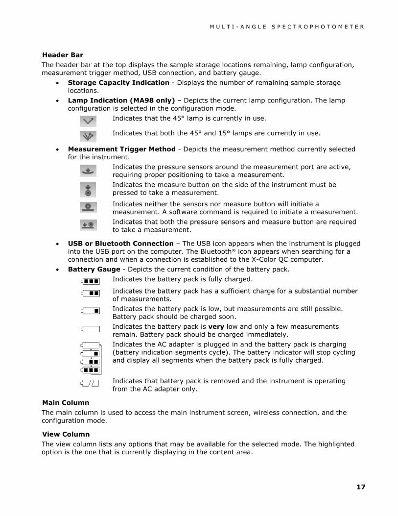
Header Bar
The header bar at the top displays the sample storage locations remaining, lamp configuration, measurement trigger method, USB connection, and battery gauge.
• Storage Capacity Indication - Displays the number of remaining sample storage locations.
• Lamp Indication (MA98 only) – Depicts the current lamp configuration. The lamp configuration is selected in the configuration mode.
Indicates that the 45° lamp is currently in use.
Indicates that both the 45° and 15° lamps are currently in use.
• Measurement Trigger Method - Depicts the measurement method currently selected for the instrument.
Indicates the pressure sensors around the measurement port are active, requiring proper positioning to take a measurement.
Indicates the measure button on the side of the instrument must be pressed to take a measurement.
Indicates neither the sensors nor measure button will initiate a measurement. A software command is required to initiate a measurement.
Indicates that both the pressure sensors and measure button are required to take a measurement.
• USB or Bluetooth Connection – The USB icon appears when the instrument is plugged into the USB port on the computer. The Bluetooth® icon appears when searching for a connection and when a connection is established to the X-Color QC computer.
• Battery Gauge - Depicts the current condition of the battery pack.
Indicates the battery pack is fully charged.
Indicates the battery pack has a sufficient charge for a substantial number of measurements.
Indicates the battery pack is low, but measurements are still possible. Battery pack should be charged soon.
Indicates the battery pack is very low and only a few measurements remain. Battery pack should be charged immediately.
Indicates the AC adapter is plugged in and the battery pack is charging (battery indication segments cycle). The battery indicator will stop cycling and display all segments when the battery pack is fully charged.
Indicates that battery pack is removed and the instrument is operating from the AC adapter only.
Main Column
The main column is used to access the main instrument screen, wireless connection, and the configuration mode.
View Column
The view column lists any options that may be available for the selected mode. The highlighted option is the one that is currently displaying in the content area.

M U L T I - A N G L E S P E C T R O P H O T O M E T E R
18
Content Area
The content area displays the data, steps, and graphs for the currently selected option.
Progress Column
The progress column displays icons used to activate a step sequence, delete samples, page through stored samples, and toggle between color space options and graph view.
Wireless Operation If available, the instrument uses Bluetooth® technology and can communicate wirelessly with your computer. Data from the X-Color QC application can be transmitted within a short range (<10 m) to/from the instrument.
To utilize the Bluetooth feature in the MA9x, you must pair the instrument with the Bluetooth adapter in your Windows computer. The pairing procedure is only required the very first time you use the wireless feature to establish a connection. Once complete, the instrument automatically connects to the computer when used. Please see the procedure that follows to pair your instrument to the computer.
Pairing Procedure
1. Make sure the USB cable is not connected to the instrument.
2. Use the Navigation buttons to move the highlight focus to the Bluetooth® icon in the Main column (USB must be disconnected).
3. Press the Select button to put the instrument into discoverable mode. The instrument will stay in discoverable mode for up to 60 seconds. If a connection is not successful after 60 seconds, the connection attempt will stop. If this occurs, you will need to reselect the Bluetooth icon before continuing.
4. Start the Windows procedure for pairing a Bluetooth device. For additional information on this
procedure, select Help and Support in the Windows Start menu.
5. When required, select the MA9x_... icon from the list of available devices and enter the pairing code default (lowercase) into the available field.
6. After pairing is successful, you are now ready to use the MA9x in wireless mode.
7. Refer to the X-Color QC application for information on transferring standard and sample data.
Bluetooth icon appears in the header bar when searching and while connected.

M U L T I - A N G L E S P E C T R O P H O T O M E T E R
19
CONFIGURATION MODE
Configuration mode is used to adjust and view the instrument’s settings. You should set the configuration options before using the instrument for the first time. However, you can go back and change these settings at any time. Each configuration option is explained in detail on the following pages.
Entering Configuration Mode 1. From the Main screen, use the Navigation buttons to move the highlight focus to the
Configuration icon.
2. Press the Select button to access the main configuration screen. The screen displays the
instrument information (model, serial number and firmware).
3. From the Configuration screen, use the Up or Down navigation buttons to move the highlight focus to the desired configuration icon in the Options column.
NOTE: The arrow icon ( or ) at the end of the Options column indicates that additional options are available. Move the highlight focus to the arrow icon and press the Select button to access the additional options.
4. Press the Right navigation button to enter the option settings area.
5. Use the Up or Down navigation buttons to move the highlight focus to the desired setting and press the Select button to change your setting. An arrow () appears next to the selected setting.
6. Press the Left navigation button to return to the Options column.
Configuration mode icon
Options column
Instrument information screen
Available settings

M U L T I - A N G L E S P E C T R O P H O T O M E T E R
20
Exiting Configuration Mode
After configuring options, use the Left navigation button to move the highlight focus to the Main screen icon in the Main column and press the Select button to exit.
Lamp Selection (MA98 only)
This option is used to select single (default) or dual lamp configuration in the instrument.
Single Lamp – Indicates the 45° lamp is only in use.
Dual Lamp - Indicates both the 45° lamp and 15° lamp are in use.
Measurement Trigger
This option is used to determine which inputs are used to trigger a measurement on the instrument. The available settings are Pressure (default), Button, Software Only, and Pressure and Button.
Pressure – Pressure sensors are required to take a measurement.
Button – Measure button is required to take a measurement.
Software Only – No button or pressure sensors are required to take a measurement. This setting would be selected when software input is used to trigger a measurement.
Pressure and Button – Both the pressure sensors and measure button are required to a take a measurement.
Pressure Sensor Sensitivity
This option works in conjunction with the pressure sensor measure option, by allowing you to adjust the amount of pressure required before a reading would occur. The available settings are Minimum, Light (default) and Normal.
Minimum – A minimal amount of pressure is required to trigger a measurement.
Light – Little pressure is required to trigger a measurement.
Normal – Firmer pressure is required to trigger a measurement. This option would be used when very precise positioning is always required.
Main screen icon

M U L T I - A N G L E S P E C T R O P H O T O M E T E R
21
Averaging
This option is used to set the number of measurements required for calculating a single measurement. Measurements are taken at different locations on a sample to achieve average measurement values. The available settings are No Averaging (default), Simple Average of 2, 3, 4, and 5, and SMC. SMC settings are SMC 5:12, SMC 10:12, SMC 20:20, and Custom SMC 50:5. The first number after SMC indicates the grade limit followed by the number of measurements allowed. Custom SMC setting is adjustable through the Configuration screen in X-Color QC.
SMC (Statistical Measurement Control) is a method of performing a statistical analysis of several measurements to determine the quality of the measurements and/or the sample, before an average value is calculated. A statistical analysis of the measurements' mean and standard deviations eliminates outliers and determines the variability of the measurements. Additional measurements may be required until a minimum of 5 outlier-free measurements are achieved, or the sample is determined too variable.
Calibration Timeout
This option is used to set the amount of time that elapses before a calibration is required. The available settings are: Disabled, 8 Hours, 12 Hours, 24 hours (default), 48 Hours, and 1 Week.
Sample Storage
This option is used to enable or disable (default) the storage of samples in the instrument.
Enabled – Sample storage is on.
Disabled - Sample storage is off.
Sample Deletion
This option is used to enable or disable (default) the ability to delete stored samples in the measure mode. NOTE: The option requires sample storage to be enabled.
Enabled – Allows sample deletion.
Disabled - Disallows sample deletion.
Sample History
This option is used to enable (default) or disable the ability to view stored samples in the measure mode. NOTE: The option requires sample storage to be enabled.
Enabled – Allows stored sample navigation.
Disabled - Disallows stored sample navigation.
Standard Selection Method
This option is used to set auto standard (default) or manual standard.
Auto Select – The instrument automatically selects a stored standard that is the closest to the sample being measured.
Manual Select – A standard must be selected before a measurement.

M U L T I - A N G L E S P E C T R O P H O T O M E T E R
22
Standard Creation
This option is used to enable or disable (default) the ability to create standards in the Measure mode.
Enabled – Allows standard creation.
Disabled - Disallows standard creation.
Group Selection
This option is used to enable (default) or disable the ability to select a standard group in the measure mode. Grouped standards are downloaded into the instrument using the X-Color QC software application.
Enabled – Group selection is allowed.
Disabled – No group selection is allowed.
Allowed Color Spaces
This option is used to select the allowed color spaces that appear in the Measure Mode. You can select as many color spaces as desired.
An arrow () appears next to the selected color spaces.
Allowed Illuminant/Observers
This option is used to select the allowed illuminant/observer combinations that appear in the Measure Mode. You can select as many illumination/observers as desired.
An arrow () appears next to the selected illuminant/observer combinations.
Language
This option is used to set the language that is displayed on the instrument. The available settings are English (default), German, French, Spanish, Italian, Chinese Simplified, and Japanese.
Date Format
This option is used to adjust the date format the instrument uses. The available settings are: MM/DD/YYYY (default), DD/MM/YYYY, DD.MM.YYYY, YYYY/MM/DD, and YYYY-MM-DD.
NOTE: The date format automatically changes to the correct format for the selected language. If desired, you can change the format after selecting the language.
Beeper Volume
This option is used to adjust the volume of the instrument speaker. The instrument beeps after a measurement and calibration. The available settings are: Off (default), Low, and High.

M U L T I - A N G L E S P E C T R O P H O T O M E T E R
23
Display and Power Down Time
This option is used to set the desired display and power down time. The available settings are Disabled, Long, Medium (default), and Short. All times are ignored when the AC adapter is plugged into the instrument.
Disabled – The instrument goes into standby mode after 24 hours of inactivity. The instrument never shuts completely off in this mode.
Long – The instrument goes into standby mode after 60 minutes and shuts completely off after 2 hours of inactivity.
Medium - The instrument goes into standby mode after 5 minutes and shuts completely off after 15 minutes of inactivity.
Short - The instrument goes into standby mode after 1 minute and shuts completely off after 2 minutes of inactivity.
Instrument Orientation
This option is used to change the display direction to accommodate both right and left handed users. The available settings are Right Handed (default) and Left Handed.
Clear All Samples
This option is used to clear all samples stored in the instrument. To clear all samples, use the Right navigation button to move highlight focus to the check mark icon in the Progress column and press the Select button.
Load Defaults
This option is used to restore the instrument’s configuration settings back to their original factory settings. To restore the default settings, use the Right navigation button to move highlight focus to the check mark icon in the Progress column and press the Select button.

M U L T I - A N G L E S P E C T R O P H O T O M E T E R
24
CALIBRATION MODE
The instrument comes with a calibration reference and black trap. A calibration should be performed when called for by the instrument or when desired. The calibration timeout is set in Configuration mode.
Refer to Cleaning section in the Appendices for information on cleaning the optics area and references.
NOTE: Make sure to use the calibration reference supplied with the instrument for calibrating. Do not substitute this reference with a reference from another instrument. The serial number on the reference should match the reference (plaque) serial number displayed in the main calibration screen.
Calibration Notes
• Dirt or dust in the aperture area will cause an inaccurate calibration reading. Refer to the Appendices for optics cleaning procedure.
• The white plaque in the calibration reference is dramatically affected by smudge marks, dust, and finger prints. Refer to Appendices for calibration reference cleaning procedures.
• The black trap should be cleaned periodically to remove any dust or contamination. Refer to Appendices for black trap cleaning procedures.
• Do not move instrument while taking a calibration measurement. If motion is detected, an error message will be displayed and calibration aborted.
Positioning the Instrument on the Black Trap The black trap is used to perform the zero reflectance measurements. The instrument’s measurement port is positioned over the opening. The black trap snaps onto the instruments measurement port and can only be positioned in one direction. The black trap can be taken apart for easy cleaning. Refer to the Appendices for procedure on cleaning the black trap.
Always store the black trap with the hole plug installed.
Measurement opening
Black trap properly positioned
Hole plug

M U L T I - A N G L E S P E C T R O P H O T O M E T E R
25
Positioning the Instrument on the Calibration Reference The calibration reference is designed to keep the white plaque free of dust and debris. The white plaque is concealed in a case that has a hinged cover. The measurement port is positioned on the white plaque and the measurement taken. Make sure the white plaque in the calibration reference is positioned squarely under the measurement port, with the cover open to the Measure button side of the instrument.
Calibrating the Instrument 1. From the Main screen, use the Navigation buttons to move the highlight square to the
Calibration icon.
2. Press the Select button to access the calibration screen.
White Calibration Expired appears if calibration is needed. If calibration is not currently needed, the time remaining before the next calibration, along with the temperature of the last calibration and white reference (plaque) serial number will appear. To exit calibration mode without calibrating, select the Exit icon (x) in the Progress column.
Exit icon
Calibration reference properly positioned
White plaque
Hinged cover
Calibration mode icon
Next icon
Information that appears when calibration is not
currently required

M U L T I - A N G L E S P E C T R O P H O T O M E T E R
26
3. Use the Right navigation button to move the highlight focus to the Progress column. Use the Down navigation button to highlight the Next arrow icon (→) if not highlighted and press the Select button.
4. Remove the hole plug and snap the instrument on the black trap as previously explained. Make sure the Next arrow icon (→) is highlighted in the Progress column and press the Select button.
The instrument takes 4 or 8 measurements depending on the model. After the black calibration measurements are complete, remove the instrument from the black trap, install the hole plug, and return the black trap to its storage location.
NOTE: If an error message appears during or after black trap calibration, press the Select button to clear the message and try measuring the black trap again. If an error still occurs, clean the black trap as explained in the Appendices.
5. Position the instrument on the white reference as previously explained and press the Select button. Take the measurement(s) by applying the appropriate amount of pressure to the port to activate the pressure sensors (green indicator LEDs). Hold the instrument steady throughout the measurement sequence.
The instrument takes 1 or 2 measurements depending on the model. After the white calibration measurement(s) is complete, press the Select button to return the display to the main screen.
Remove the instrument from the calibration reference and return the reference to its storage location.
NOTE: If an error message appears during or after white calibration, Press the Select button to clear the message and try measuring the white reference again. If an error still occurs, clean the white calibration reference as explained in the Appendices.
M U L T I - A N G L E S P E C T R O P H O T O M E T E R
27
MEASURE MODE
The measure mode is the main operation mode of the instrument used to analyze and collect sample data. After taking a measurement, you can view the results for the angles under various color spaces and illuminant/observer combinations.
NOTE: You must select a standard if auto standard is disabled before measuring.
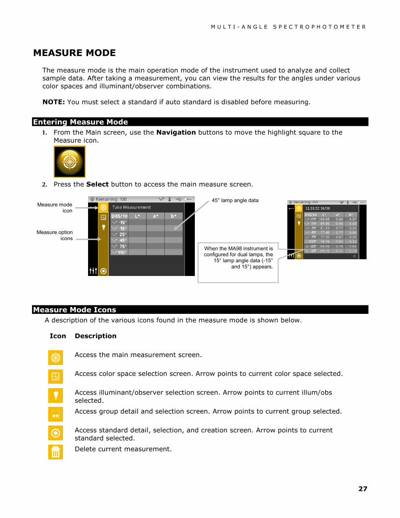
Entering Measure Mode 1. From the Main screen, use the Navigation buttons to move the highlight square to the
Measure icon.
2. Press the Select button to access the main measure screen.
Measure Mode Icons A description of the various icons found in the measure mode is shown below.
Icon Description
Access the main measurement screen.
Access color space selection screen. Arrow points to current color space selected.
Access illuminant/observer selection screen. Arrow points to current illum/obs selected.
Access group detail and selection screen. Arrow points to current group selected.
Access standard detail, selection, and creation screen. Arrow points to current standard selected.
Delete current measurement.
Measure mode icon
45° lamp angle data
Measure option icons
When the MA98 instrument is configured for dual lamps, the
15° lamp angle data (-15° and 15°) appears.

M U L T I - A N G L E S P E C T R O P H O T O M E T E R
28
Pages through the list of color spaces allowed in the Configuration mode.
Access graph view screen.
Access quick compare function.
Exits sample averaging for the current sample.
SMC only – cancels averaging and calculates an average on previous measurements.
Access previous measurement data screen when browsing stored measurements.
Access next measurement data screen when browsing stored measurements.
Indicates a passed sample measurement.
Indicates a failed sample measurement.
Selecting a Group The group option lists grouped standards that were created and downloaded from the X-Color QC application. When multiple standard groups are available, you must select the desired group before taking a measurement when using auto standard. The auto standard select function does not recognize standards across multiple groups. The selected group is used until a different group is chosen.
NOTE: Group selection is only available if it is activated in the configuration mode.
To select a group:
1. From the Measure screen, use the Up or Down navigation buttons to move the highlight focus
to the Group icon .
2. Press the Right button to access the group selection area.
Group icon

M U L T I - A N G L E S P E C T R O P H O T O M E T E R
29
3. Use the Up or Down navigation buttons to move the highlight focus to the desired group and press the Select button. An arrow () appears next to the selected group.
4. Press the Left navigation button to return to the View column.
Manually Selecting a Standard The instrument can be set to "auto select" or "manual select" a standard in the Configuration Mode. In "auto select" mode, the instrument automatically chooses the closest standard to the measured sample. In "manual select" mode, you must choose the standard before a measurement. The manually selected standard is used until a different standard is chosen.
To select a standard:
1. From the Measure screen, use the Up or Down navigation buttons to move the highlight focus
to the Standard icon .
2. Press the Right navigation button to access the standard selection area.
Standard Icon
Available standards
Selecting No Standard causes no standards to be used during sample measurements. The Manual Select standard option must be activated in Configuration to perform this function.
Available groups

M U L T I - A N G L E S P E C T R O P H O T O M E T E R
30
3. Use the Up or Down navigation buttons to move the highlight focus to the desired standard and press the Select button. An arrow () appears next to the selected standard.
4. Press the Left navigation button to return to the View column.
Selecting a Color Space The instrument has several colorimetric systems (absolute and difference) to choose from. Any color space can be selected after a measurement to view the measurement results under a different method. The color space page icon is used to quickly page through the list of allowed color spaces without leaving the current view. Simply press the Enter key when the icon is highlighted to change to the next allowed color space.
Color Spaces L*a*b* (default) ∆L*a*b* ∆E* (default) ∆Eeff ∆E94 ∆DNA10 ∆F19 ∆SI
L*C*h° (default) ∆L*C*H* ∆Ecmc ∆Ec ∆F10 SI ∆G19 ∆IL
Flop Index ∆Flop Index ∆Ep ∆E00 ∆G10 (default) IL ∆DNA19 MA98 only
NOTE: Delta color spaces will not appear if no standard is selected. Certain color spaces may not appear if they are not allowed in the Configuration mode.
To select a color space:
1. From the Measure screen, use the Up or Down navigation buttons to move the highlight focus
to the Color Space icon .
2. Press the Right navigation button to access the color space selection area.
3. Use the Up or Down navigation buttons to move the highlight focus to the desired color space and press the Select button. An arrow () appears next to the selected color space.
4. Press the Left navigation button to return to the View column.
Available color spaces
Color space page icon Color space icon
M U L T I - A N G L E S P E C T R O P H O T O M E T E R
31
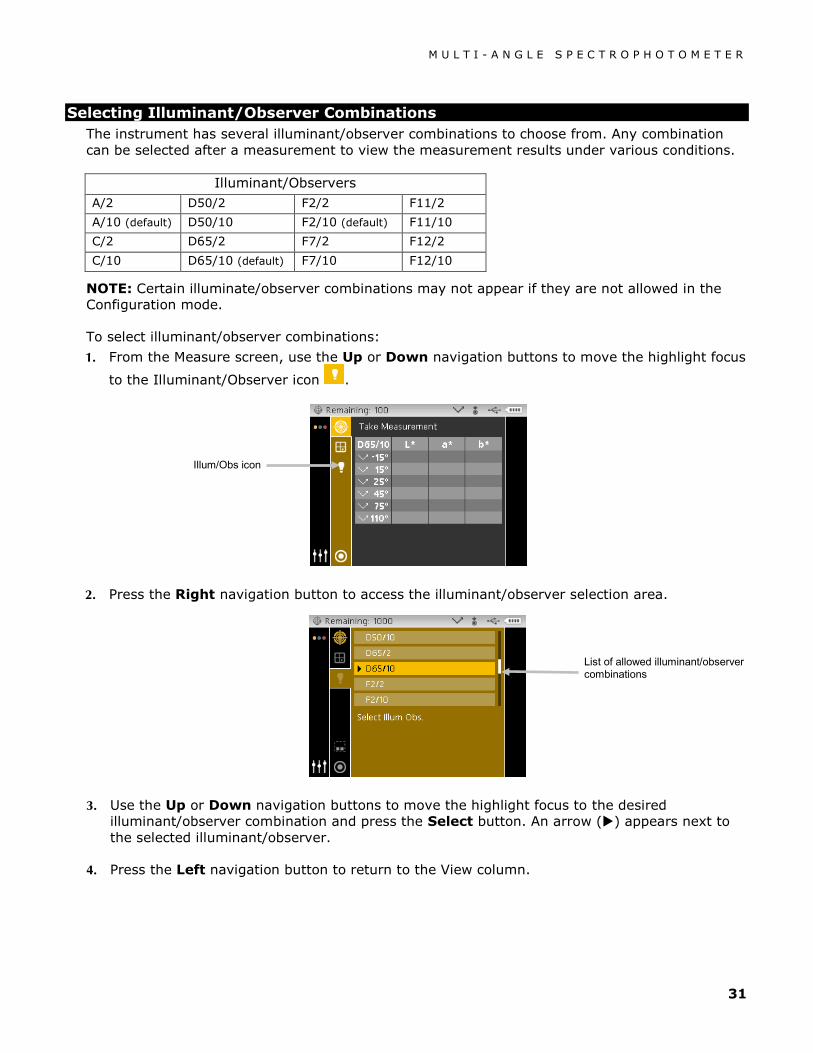
Selecting Illuminant/Observer Combinations The instrument has several illuminant/observer combinations to choose from. Any combination can be selected after a measurement to view the measurement results under various conditions.
Illuminant/Observers A/2 D50/2 F2/2 F11/2
A/10 (default) D50/10 F2/10 (default) F11/10
C/2 D65/2 F7/2 F12/2
C/10 D65/10 (default) F7/10 F12/10
NOTE: Certain illuminate/observer combinations may not appear if they are not allowed in the Configuration mode.
To select illuminant/observer combinations:
1. From the Measure screen, use the Up or Down navigation buttons to move the highlight focus
to the Illuminant/Observer icon .
2. Press the Right navigation button to access the illuminant/observer selection area.
3. Use the Up or Down navigation buttons to move the highlight focus to the desired illuminant/observer combination and press the Select button. An arrow () appears next to the selected illuminant/observer.
4. Press the Left navigation button to return to the View column.
List of allowed illuminant/observer combinations
Illum/Obs icon
M U L T I - A N G L E S P E C T R O P H O T O M E T E R
32
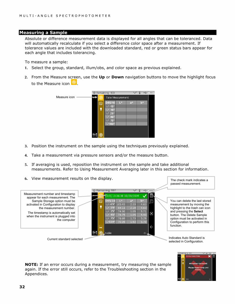
Measuring a Sample Absolute or difference measurement data is displayed for all angles that can be toleranced. Data will automatically recalculate if you select a difference color space after a measurement. If tolerance values are included with the downloaded standard, red or green status bars appear for each angle that includes tolerancing.
To measure a sample:
1. Select the group, standard, illum/obs, and color space as previous explained.
2. From the Measure screen, use the Up or Down navigation buttons to move the highlight focus
to the Measure icon .
3. Position the instrument on the sample using the techniques previously explained.
4. Take a measurement via pressure sensors and/or the measure button.
5. If averaging is used, reposition the instrument on the sample and take additional measurements. Refer to Using Measurement Averaging later in this section for information.
6. View measurement results on the display.
NOTE: If an error occurs during a measurement, try measuring the sample again. If the error still occurs, refer to the Troubleshooting section in the Appendices.
Measure icon
You can delete the last stored measurement by moving the highlight to the trash can icon and pressing the Select button. The Delete Sample option must be activated in Configuration to perform this function.
Indicates Auto Standard is selected in Configuration.
Measurement number and timestamp appear for each measurement. The
Sample Storage option must be activated in Configuration to display
the measurement number. The timestamp is automatically set
when the instrument is plugged into the computer
The check mark indicates a passed measurement.
Current standard selected

M U L T I - A N G L E S P E C T R O P H O T O M E T E R
33
Using Measurement Averaging NOTE: Measurement Averaging must be activated in Configuration before averaging can be performed. Refer to the Configuration Mode for procedure on setting averaging.
Measurement averaging can be set to Simple Average 1 to 5, or SMC 5:12, SMC 10:12, SMC 20:20, and Custom SMC 50:5. SMC (Statistical Measurement Control) requires a minimum of 5 measurements taken at various locations on a sample. Refer to Configuration Mode for additional information on SMC.
The following example has a simple average setting of 2.
To measure using averaging:
1. Select the group, standard, illum/obs, and color space as previous explained.
2. From the Measure screen, use the Up or Down navigation buttons to move the highlight focus
to the View column and then to the Measure icon .
3. Position the instrument on the first area of the sample and take a measurement. After the measurement, the instrument displays "Averaged 1 of 2" in the screen, indicating one more measurement is required for results.
Note: When averaging using SMC, a cancel icon appears in the Progress column after the third measurement. This allows you to cancel SMC and average the previous measurements for the current sample.
4. Position the instrument on the second area of the sample and take a measurement. After the measurement, the instrument momentarily displays "Processing Results" and then the averaged data values.
If you want to exit sample averaging, move the highlight to the exit icon and press the Select button. The display returns to the previous measurement.
Averaged data values
M U L T I - A N G L E S P E C T R O P H O T O M E T E R
34
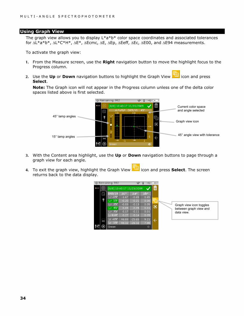
Using Graph View The graph view allows you to display L*a*b* color space coordinates and associated tolerances for ∆L*a*b*, ∆L*C*H*, ∆E*, ∆Ecmc, ∆E, ∆Ep, ∆Eeff, ∆Ec, ∆E00, and ∆E94 measurements.
To activate the graph view:
1. From the Measure screen, use the Right navigation button to move the highlight focus to the Progress column.
2. Use the Up or Down navigation buttons to highlight the Graph View icon and press Select.
Note: The Graph icon will not appear in the Progress column unless one of the delta color spaces listed above is first selected.
3. With the Content area highlight, use the Up or Down navigation buttons to page through a graph view for each angle.
4. To exit the graph view, highlight the Graph View icon and press Select. The screen returns back to the data display.
45° lamp angles
Current color space and angle selected
45° angle view with tolerance
Graph view icon toggles between graph view and data view.
Graph view icon
15° lamp angles

M U L T I - A N G L E S P E C T R O P H O T O M E T E R
35
Viewing Stored Measurements NOTE: Sample Storage must be enabled in Configuration to view stored data. Refer to the Configuration Mode for procedure on enabling sample storage.
Measurements stored can be retrieved on the instrument for viewing at a later time. The measurement data will display under the last color space and illuminant/observer combination selected.
To view stored data:
1. From the Measure screen, use the Right navigation button to move the highlight focus to the Progress column.
2. Use the Up or Down navigation buttons to highlight the or icon and press Select. Each time Select is pressed, the screen displays the next or previous store measurement.
Viewing Pass/Fail Data A red or green bar displays for any aspecular standard angle that has a tolerances set. Angles that have no tolerance set will remain gray in color. Refer to X-Rite's X-Color QC software application for information on setting tolerancing for standards.
∆L*a*b* Color Space (pass/fail)
The following two pass/fail examples are using the ∆L*a*b* color space. Tolerance limits of "0.50" were set on DL*, Da*, and Db* for the 15° and 45° angles.
This example shows the 15° and 45° angles highlighted in green, indicating those angles passed.
White check mark and green bar indicated that all angle tolerances passed.
Passed Example
Next sample icon
Previous sample icon

M U L T I - A N G L E S P E C T R O P H O T O M E T E R
36
∆L*a*b* Color Space (pass/warning)
The following is a pass/warning example using ∆L*a*b* color space. Tolerance limits of "1.00" were set to DL* Da*, and Db* for the -15°, 45°, and 110 angles. In this example, the 80% warning limit set for the -15° tolerance has been exceeded. This is indicated by a yellow highlighted checkmark and status bar for the angle.
Pass/Fail Option
The Pass/Fail display option located in the color space group gives you a quick pass/fail view of a sample. Select the [/X] option to activate the pass/fail display screen.
This example shows the 15° angle highlighted in red and the 45° angle highlighted in green, indicating the 15° angle failed.
The "X" and red bar indicate that at least one angle failed tolerance.
Failed Passed
Failed Example
Pass/Warning Example
Passed with Warning
This example shows the -15° angle highlighted in yellow has exceeded the warning limit.
Yellow checkmark and green bar indicated at least one angle has exceeded the warning limit.
The “a* attribute exceeded the 0.50 tolerance set.
The “L* attribute exceeded the 80% warning for the 1.00 tolerance set.

M U L T I - A N G L E S P E C T R O P H O T O M E T E R
37
Using Quick Compare The Quick Compare function is used for comparing measurements without storing data. You can compare measurements to a previously stored measurement or to a new measurement.
Use the color space page icon to quickly page through a list of color spaces without leaving the current view. Simply press the Enter key when the icon is highlighted to change to the next allowed color space.
To compare data:
1. Select a stored sample or take new measurement to use for comparison.
2. From the Measure screen, use the Right navigation button to move the highlight focus to the Progress column.
3. Use the Up or Down navigation buttons to highlight the Quick Compare icon and press Select. A small “x” appears next to the Compare icon and “Quick Compare” appears in the header bar. The Content Area will change to the delta color space of the last selected color space before the comparison measurement.
4. Position the instrument on the sample to compare and take the measurement.
5. View measurement result or take additional measurements.
6. To exit quick compare, highlight the Quick Compare icon and press Select. The screen returns back to the normal sample measurement mode.
Quick Compare icon
Sample to use for comparison
Quick Compare mode Color space page icon

M U L T I - A N G L E S P E C T R O P H O T O M E T E R
38
Creating Standards NOTE: The instrument must have standards loaded and Sample Storage must be enabled in Configuration to create standards.
Standards are downloaded to the instrument from X-Rite's X-Color QC software application. However, a standard can be created using the instrument. The new standard will duplicate an existing sample measurement stored with a downloaded standard. Any tolerance values that exist with that downloaded standard will get copied to the newly created standard. The instrument automatically number increments the created standards. (For example: "0002", 0003", etc). These automatically generated numbers cannot be changed on the instrument.
To create a standard:
1. From the Measure screen, use the Right navigation button to move the highlight focus to the Progress column.
2. Use the Up or Down navigation buttons to highlight the or icon and press the Select button to find the sample you want to use as a standard.
3. After the desired sample is displayed, use the Navigation buttons to move the highlight focus
back to the View column and then to the Standard icon .
4. Press the Right navigation button to access the standard selection area.
5. Use the Up or Down navigation buttons to move the highlight focus to "Create Standard" and press the Select button. A new custom standard appears in the list.
6. Press the Left navigation button to return to the View column.
Standard Icon
The Create Standard option must be activated in Configuration for it to appear in the list.
The newly created standard can now be used for sample comparison.
M U L T I - A N G L E S P E C T R O P H O T O M E T E R
39
JOB MODE
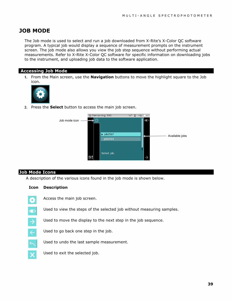
The Job mode is used to select and run a job downloaded from X-Rite’s X-Color QC software program. A typical job would display a sequence of measurement prompts on the instrument screen. The job mode also allows you view the job step sequence without performing actual measurements. Refer to X-Rite X-Color QC software for specific information on downloading jobs to the instrument, and uploading job data to the software application.
Accessing Job Mode 1. From the Main screen, use the Navigation buttons to move the highlight square to the Job
icon.
2. Press the Select button to access the main job screen.
Job Mode Icons A description of the various icons found in the job mode is shown below.
Icon Description
Access the main job screen.
Used to view the steps of the selected job without measuring samples.
Used to move the display to the next step in the job sequence.
Used to go back one step in the job.
Used to undo the last sample measurement.
Used to exit the selected job.
Job mode icon
Available jobs

M U L T I - A N G L E S P E C T R O P H O T O M E T E R
40
Selecting and Running a Job The following job example downloaded from X-Color QC consists of one instruction screen and two measurement screens.
1. Use the Up and Down navigation buttons to move the highlight focus to the desired job and press the Select button. An arrow () appears next to the selected job.
2. Use the Right navigation button to move the highlight focus to the Progress column. Use the Down navigation button to highlight the Next arrow icon (→) if not selected and press the Select button to open the job. The first step in the job sequence is displayed.
3. Make sure the Next arrow icon (→) is selected and press the Select button.
4. Position the instrument on the sample as described on the screen and take the measurement.
Available jobs
Next arrow icon
1st step instruction
2nd step measurement instruction with graphic
Instructions screen
Measurement screen

M U L T I - A N G L E S P E C T R O P H O T O M E T E R
41
5. Data for the first measurement appears on the display. Make sure the Next arrow icon (→) is selected and press the Select button.
6. Position the instrument on the sample as described on the screen and take the measurement.
7. Data appears on the display for the second measurement.
8. The job is now completed. Make sure the Next arrow icon (→) is selected and press the Select button to return to the main job screen.
1st measurement data
Next arrow icon
3rd step measurement instruction with graphic
2nd measurement data

M U L T I - A N G L E S P E C T R O P H O T O M E T E R
42
APPENDICES
Service Information X-Rite provides repair service to their customers. Because of the complexity of the circuitry, all warranty and non warranty repairs should be referred to an authorized service center. For non warranty repairs, the customer shall pay shipping and repair cost to the authorized service center, and the instrument shall be submitted in the original carton, as a complete unaltered unit, along with all the supplied accessories.
X-Rite, Incorporated has offices around the world. You can contact us using one of the following methods:
• To identify the X-Rite service center nearest you, please visit our web site at www.xrite.com and click the Contact Us link.
• For online help, visit our web site and click the Support link. Here you can search for software or firmware updates, white papers, or frequently asked questions which can quickly resolve many common user problems.
• Send an e-mail to Technical Support ([email protected]) detailing your problem and listing your contact information.
• For sales questions or to order cables and accessories, visit our web site or contact your nearest X-Rite dealer or service center.
• Problems and questions can also be faxed to your local X-Rite office listed on our web site.

M U L T I - A N G L E S P E C T R O P H O T O M E T E R
43
Cleaning the Instrument Your instrument requires very little maintenance to achieve years of reliable operation. However, to protect your investment and maintain reading accuracy, a few simple-cleaning procedures should be performed from time to time.
General Cleaning
The exterior of the instrument may be wiped clean with a cloth dampened in water or mild cleaner.
NOTE: DO NOT use any solvents to the clean the instrument, this will cause damage to the cover.
Cleaning the Optics
The optics should be cleaned once a week in a normal environment. If the instrument is used in a dirty or dusty environment, more frequent cleaning may be required.
Carefully lift the instrument and blow short bursts of clean, dry air into the measurement port. This should remove any accumulated debris from the optics.
IMPORTANT: If can air is used for cleaning, do not invert or tilt the can during use. This could cause damage to the optics.
Cleaning the Calibration Reference
The white plaque in the calibration reference should be cleaned using a mild soap and warm water solution, thoroughly rinsed with warm water, and wiped dry with a clean, lint-free cloth. You must let the plaque dry completely before taking a calibration measurement.
M U L T I - A N G L E S P E C T R O P H O T O M E T E R
44
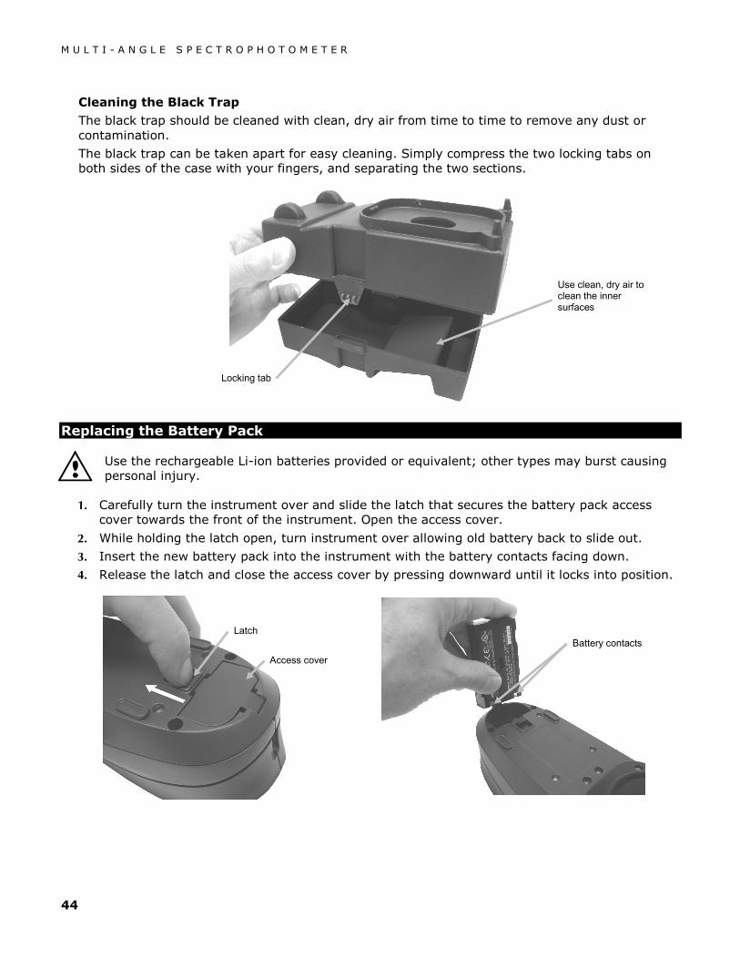
Cleaning the Black Trap
The black trap should be cleaned with clean, dry air from time to time to remove any dust or contamination.
The black trap can be taken apart for easy cleaning. Simply compress the two locking tabs on both sides of the case with your fingers, and separating the two sections.
Replacing the Battery Pack
Use the rechargeable Li-ion batteries provided or equivalent; other types may burst causing personal injury.
1. Carefully turn the instrument over and slide the latch that secures the battery pack access cover towards the front of the instrument. Open the access cover.
2. While holding the latch open, turn instrument over allowing old battery back to slide out.
3. Insert the new battery pack into the instrument with the battery contacts facing down.
4. Release the latch and close the access cover by pressing downward until it locks into position.
Locking tab
Use clean, dry air to clean the inner surfaces
Access cover
Latch Battery contacts

M U L T I - A N G L E S P E C T R O P H O T O M E T E R
45
Troubleshooting Prior to contacting X-Rite support department for instrument problems, try the applicable solution(s) described below. If the condition persists, contact us using one of the methods listed in the Service Information section.
Problem Cause Solution
Instrument not responding.
Instrument is in power down mode.
Press and hold the Select button for 3 seconds to wake up the instrument.
Battery pack is very low or bad.
Charge the battery. If battery pack is bad, replace using the procedure in the Appendix.
Reset the instrument. See Appendix for procedure.
No battery pack installed. Install batteries or plug in AC adapter.
Measurement error or results appear inaccurate.
Material being measured is damaged (e.g. scratched)
Obtain new material.
Optics requires cleaning. Refer to Optics cleaning procedure in Appendix for procedure.
Instrument requires calibration.
Refer to Calibration mode for procedure.
Calibration procedure fails.
Calibration reference is dirty or damaged.
Clean the reference per procedure in Appendix, or replace if damaged.
Instrument and software not communicating (USB connection).
Interface cable not connected.
Connect the interface cable between the computer and the instrument.
Close and restart the software application. If this does not work, reboot the computer.
Reset the instrument. See Appendix for procedure.
Instrument and software not communicating (wireless connection).
Wireless function not activated.
Activate Bluetooth wireless connection in the device. Refer to the Wireless Operation section for information.
Activate Bluetooth wireless connection on your computer. Refer to the manufacturer's manual of your computer.
Close and restart the software application. If this does not work, reboot the computer.
Reset the instrument. See Appendix for procedure.

M U L T I - A N G L E S P E C T R O P H O T O M E T E R
46
Screen Messages Screen messages can appear on the display during error conditions or for informational purposes. Some messages are cleared from the instrument screen by navigating to the "X" icon and pressing the Select button.
Messages may also be accompanied by a number to indicate a specific condition. If an error condition persists, please contact our technical support using one of the methods listed in the Service Information section.
Resetting the Instrument To reset the instrument:
1. Unplug the interface cable and AC adapter from the instrument if connected.
2. Open the battery access cover and remove the battery.
3. Reinstall the battery and power up the instrument.
If you are still experiencing problems after a reset, contact X-Rite support using one of the methods listed in the Service Information section.
Sample Error Message

M U L T I - A N G L E S P E C T R O P H O T O M E T E R
47
Instrument Specifications General
Measurement Geometries
Illumination: 45°
Aspecular Viewing: -15° (MA96, MA98), 15°, 25°, 45°, 75°, 110°
Out-of-plane (MA98): 25°az90°, 25°az-90°, 60°az125.3°, 60°az-125.3°
Secondary Illumination (MA98): 15°
Aspecular Viewing (MA98): -15°, 15°
Angular Accuracy: ±0.15° Fiber Optic pick up coupled with DRS technology
Measuring Area: Approx. 12 mm (.5")
Light Source: Gas filled tungsten lamp
Lamp Life: 750,000 measurements, typical
Spectral Range: 400nm – 700nm
Spectral Interval: 10nm (31 measured points)
Measurement Range: 0 - 400%
Colorimetric Illuminants: A, C, D50, D65, F2, F7, F11 and F12
Colorimetric Standard Observers: 2° & 10°
Colorimetric Scales: L*a*b*, L*C*h°, ∆E*, ∆ECMC, ∆E DIN6175, ∆E2000
Effect Parameters: xDNA, Flop Index
Measurement Time: Approx. 2 seconds
Reproducibility: 0.18 ΔE* avg on reference Series II BCRA tile set
(Inter-instrument agreement)
Repeatability: 0.03 ∆E* on white cal plaque (20 measurements at 5 sec intervals)
Power Supply: Rechargeable Lithium Ion battery pack 7.4vDC @ 2400 mAh
AC Adapter: Input 100-240V 50-60 Hz Output 12VDC @ 2.5 A
Measurements per charge: Up to 750
Measurement storage: 250 Standards 1000 Samples
Data interface: USB 2.0
Weight: 2.5 lbs (1.13 kgs)
Dimensions: 3.4 x 4.5 x 10.6 (8,7 cm x 11,4 cm x 26,9 cm)
M U L T I - A N G L E S P E C T R O P H O T O M E T E R
48
Environmental
Operating Temp: 50°F to 104°F (10°C to 40°C)
Humidity Max: 85% RH max (non condensing)
Storage Temp: -4°F to 122°F (-20°C to 50°C)
Usage: Indoor Only
Altitude: 2000m
Pollution Degree: 2
Transient Overvoltage: Category II
Standards
ASTM: D 2244, E 308, E 1164, E 2194, E 2539 (MA98)
DIN 5033, 6174, 6175-2
ISO 7724
SAE J1545
Design and specifications subject to change without notice.


Corporate Headquarters X-Rite, Incorporated 4300 44th Street SE Grand Rapids, Michigan 49512 Phone 1 800 248 9748 or 1 616 803 2100 Fax 1 800 292 4437 or 1 616 803 2705 European Headquarters X-Rite Europe GmbH Althardstrasse 70 8105 Regensdorf Switzerland Phone (+41) 44 842 24 00 Fax (+41) 44 842 22 22 Asia Pacific Headquarters X-Rite Asia Pacific Limited Suite 2801, 28th Floor, AXA Tower Landmark East, 100 How Ming Street Kwun Tong, Kowloon, Hong Kong Phone (852)2568-6283 Fax (852)2885 8610 Please visit www.xrite.com for a local office near you.
P/N MA98-500 Rev. I