multhiphase pumps for minas losf.pdf
TRANSCRIPT

8/13/2019 Multhiphase Pumps for Minas LOSF.pdf
http://slidepdf.com/reader/full/multhiphase-pumps-for-minas-losfpdf 1/10
Copyright 1999, Society of Petroleum Engineers Inc.
This paper was prepared for presentation at the 1999 SPE Asia Pacific Oil and GasConference and Exhibition held in Jakarta, Indonesia, 20–22 April 1999.
This paper was selected for presentation by an SPE Program Committee following review ofinformation contained in an abstract submitted by the author(s). Contents of the paper, aspresented, have not been reviewed by the Society of Petroleum Engineers and are subject tocorrection by the author(s). The material, as presented, does not necessarily reflect anyposition of the Society of Petroleum Engineers, its officers, or members. Papers presented atSPE meetings are subject to publication review by Editorial Committees of the Society ofPetroleum Engineers. Electronic reproduction, distribution, or storage of any part of this paperfor commercial purposes without the written consent of the Society of Petroleum Engineers isprohibited. Permission to reproduce in print is restricted to an abstract of not more than 300
words; illustrations may not be copied. The abstract must contain conspicuousacknowledgment of where and by whom the paper was presented. Write Librarian, SPE, P.O.Box 833836, Richardson, TX 75083-3836, U.S.A., fax 01-972-952-9435.
AbstractMultiphase pumps are modified liquid pumps that are capable
of pumping various combinations of oil, water, gas, and sand
in the same pipeline without separation. Minas Light Oil
Steam Flood (LOSF) Pilot Project will utilize the multiphase
technology to boost casing fluid with high steam and gas
content from wells to the Gathering Station without prior
separation. Hence, tremendous savings in capital and
operating costs are realized from strategic placement of
multiphase pumps since large separators, liquid pumps and
compressors are eliminated.Two uniquely different multiphase pumps, a 500 hp twin-
screw pump and a 700 hp helico-axial pump, were recently
tested and qualified at the Texaco Multiphase Flow Facility,
where flow rates as high as 145,000 BPD and gas volume
fractions (GVF) up to 100% were achieved. An illustration of
each pumping unit is given followed by a presentation of
measured performance data relative to the operating conditions
chosen by Caltex Pacific Indonesia (CPI). Based on test
results, the advantages and disadvantages of the competing
technologies are compared, noting that CPI will eventually
consider these data to choose either twin-screw or helico-axial
technology for the Minas Light Oil Steam Flood project.
Results obtained at the Texaco Multiphase Flow Facilityindicate that twin-screw pumps are 25% more efficient than
helico-axial pumps. Furthermore, twin-screw pumps are
virtually insensitive to liquid slugs and large changes in inlet
gas density; helico-axial pumps require slug catchers upstream
of the pump inlet to absorb these intermittent slugs and large
variations in GVF. It is anticipated, however, that helico-axial
pumps are superior in resisting long-term wear from
continuous exposure of sand, which will be investigated in
Duri in the fourth quarter of 1998.
IntroductionThe nature of steam flood in Minas field is quite unique since
the light Minas oil (32° API) is so volatile that casing vapors
must be produced. Production streams from both casing and
tubing must be piped to the Bulk Metering Station and thenusing the existing lines, to the gathering station. In these lines
LOSF flow will be quenched by ‘colder’ fluid from other parts
of the Minas field which are water injected.
Simulations show a significant percentage of the oi
production will be vapors. Closed casings would severely
hamper production rates, and vapors would be produced
through the tubing anyway. Having vapors in tubing is very
undesirable since this will seriously affect the performance of
multi-stages centrifugal pump downhole. Therefore a casing
vapor collection is required.
In order to promote both high rates of inflow from the
reservoir and natural flow, Minas wellhead casing pressures
must be drawn to a relatively low value, 60 psig. Howeverpreliminary calculations showed that the existing gathering
system would not support the expected amount of these steam-
dominant vapors at pressure below 60 psig. Some alternatives
could be adopted to solve this problem, among them are:
• Cool the casing vapors at locations near the well heads.
• Use multiphase pumps to boost casing streams to
gathering station.
The first option means that HC condensates and water mus
be separated from steam. This choice would requires various
different equipment, higher OPEX (energy cost especially) and
more intensive maintenance efforts. If a separate line would
not be built to transport the liquids to the gathering station, the
stream must be piped to the existing lines. Hence, this coolingwould be inefficient since the streams will be quenched
anyway. Therefore, LOSF design team decided to implemen
the later alternative.
Multiphase pump application becomes critical when steam
including light oil vapors reach producing wells. This will
happen 1.0 to 2.5 years after injection. The implementation o
multiphase pump is expected to:
SPE 54294
Multiphase Pumps for Minas Light Oil Steam Flood, Sumatra-IndonesiaErwinsyah Putra, Caltex Pacific Indonesia and Donald D. Uphold, Texaco

8/13/2019 Multhiphase Pumps for Minas LOSF.pdf
http://slidepdf.com/reader/full/multhiphase-pumps-for-minas-losfpdf 2/10
2 E. PUTRA, D.D. UPHOLD SPE 54294
• Boost casing stream to tubing stream pressure
• Reduce volumetric flow rate of casing fluids through
condensations across the pump
• Reduce wellhead pressures and therefore enhance well
productions.
The Minas multi phase pump must also be capable of
handling:
• Unsteady flow rates and terrain slugs• Sand production
• High temperature (up to 320 °F)
Multiphase Pump SelectionTwo commercially available technologies are being
considered, twin-screw and helico-axial.
Details of each technology will be presented later. To
determine which technology is most suitable for Minas-LOSF
application, each pump would undergo several tests to evaluate
its performances. The design point is described as follows:
• Suction pressure: 75 psig
• Differential pressure: 100 psi
• Gas Volume Fraction/GVF: 75%
• Capacity: 125,000 ABPD
The first test was conducted at Texaco Flow Loop Test
Facilities at Humble. The test matrix consisted of:
• Design point test
• High speed test
• High GVF test (up to 100% GVF, run dry)
At Humble, the process fluid was homogeneous multiphase
mixture of Fuji crude oil (30° API), water and methane heated
to 200 °F.
The final test will be conducted in Duri field in last quarter
of 1998. Both pumps will be exposed to multiphase mixtures
containing oil, water, gases (including CO2 and H2S), wetsteam and sand. The temperature may reach as high as 300 °F.
Data from Humble and Duri plus pump’s economics will
determine which technology is best for Minas-LOSF Pilot
Project.
Helico-axial TechnologyA 7-stage rotodynamic pump equipped with a 700 hp motor
and a Variable Frequency Driver was chosen for testing.
Figure 1 and 2 illustrate the helico-axial pump. This pump is a
horizontal seven-stage multiphase pump of the helico-axial
design. The collection of stages accommodates variable
reduction in gas volume flow rate as the fluid moves through
the pump. The hydraulic components are designed to preventgas-liquid separation, which would otherwise produce
diminished head, or vapor lock, as is common in conventional
centrifugal pumps.
Each stage of the pump consists of a rotating helico-shaped
impeller and a stationary diffuser, yielding a hybrid between a
dynamic pump and an axial compressor that allows a wide
range of liquid flow rates and inlet gas concentration.
Each impeller provides pressure boost and the interstage
diffuser homogenizes and redirects the flow for the next set of
impellers. This interstage mixing increases the overal
efficiency and enables stable pressure-flow characteristics.
The nature of open-axial hydraulics allows higher tota
flow rates compared to their competitive counterpart twin
screw pump. This is especially important when considering
the production life of the field for maximizing oil recoveryAdditionally, open-axial passages accommodate solid particle
and minimize accumulation in the pump casing. Finally, open
axial flow minimizes the risk of mechanical seizing due to
overheating at high GVF.
In theory, a rotodynamic pump creates pressure
dynamically, where shaft torque is converted into angular
momentum. Hence, differential pressure depends on moto
speed and inlet fluid density. This makes rotodynamic pump
extremely sensitive to small changes in inlet conditions
Hence, large changes in shaft torque under intermittent flow
are common with rotodynamic pumps. Three features are
offered to smooth these disturbances: mechanical design
improvements, flow homogenizer (buffer tank), and variablespeed capabilities. Firstly, the impellers are stacked with a
small interference shrink fit in order to maintain a smal
residual unbalance. The torque is transmitted to the impeller
with a single key or pin. Two (2) anti friction roller bearings
stabilize radial thrust and one tilting-pad thrust bearing carries
the axial load. Secondly, the buffer tank, or static mixer, i
installed upstream of the pump to accommodate slug flow
The buffer tank absorbs energy of liquid slug fronts and
smoothens out fluctuations in gas density and pressure. Hence
repetitive torque changes within the pump are minimized
Finally, the variable speed drive (VFD) adjusts the motor
speed to maintain constant inlet pressure. Differentia
temperature across the pump casing is expected to increasewith increasing GVF. Special care has been taken to minimize
this differential temperature (i.e., internal design modification
thermal insulation) as it could potentially damage the rotor and
diffusers due to thermal distortion of the shaft.
The rotodynamic pump utilizes only one rotating shaft, or
rotor. The pump rotor (with impellers), diffusers, bearings
shaft seals and cover are designed as a cartridge assembly
which is introduced into the casing to reduce maintenance
downtime. The single shaft principle is simple and permits
higher rotational speeds (up to 3,600 rpm for this specific unit
when compared to the twin-screw counterpart (up to 2300
rpm). Process fluid enters through a vertical inlet. The initia
stage homogenizes the fluid and prepares it for the firsboosting stage. Fluid is then pumped axially via seven
impeller/diffuser stages, where the fluid builds pressure
dynamically. The hydraulic stages are sized according to the
principle that most of the compression occurs during the later
stages. Process fluid then discharges vertically. Recall that a
tilt-pad thrust bearing assembly is installed at the non-drive
end of the pump to handle the axial load and maximize roller

8/13/2019 Multhiphase Pumps for Minas LOSF.pdf
http://slidepdf.com/reader/full/multhiphase-pumps-for-minas-losfpdf 3/10

8/13/2019 Multhiphase Pumps for Minas LOSF.pdf
http://slidepdf.com/reader/full/multhiphase-pumps-for-minas-losfpdf 4/10
4 E. PUTRA, D.D. UPHOLD SPE 54294
consumed to compress Duri gas, developing less differential
pressure at a chosen speed on the diagram. These effects will
be further studied in Duri.
The pump system performance at this high ∆P condition is
quite impressive. It appears the system was intended to
operate at this point rather than the design point. Furthermore
as illustrated in Fig. 5, efficiency is optimized when operating
near this condition, suggesting the BEP occurs near the high-∆P point. Alternatively, this finding confirms a safety factor to
withstand routine wear from elevated temperatures and solids
content while operating at the design point for an extended
period of time. If this is the case, this pump should fare much
better than the twin-screw pump over the production life in the
Minas LOSF.
The pump successfully demonstrated operation up to 94%
GVF with very little discharge temperature build-up over the
suction temperature. However, the pump was only capable of
developing 25 psi differential pressure at this GVF. In
addition, hydraulic efficiency dramatically dropped to 16%.
Attempting to increase the GVF above 94% caused inlet
pressure to drop below 60 psig, tripping the pump on lowsuction pressure. These results question the effectiveness of
rotodynamic pumps at high GVF. Buffer tanks located
upstream of the pump may smooth off intermittent gas spikes
(as long as liquid is initially present in the tank).
Figures 6 and 7 contain families of curves generated from
test data. Figure 6 is differential pressure ∆P (psi) versus total
flow rate; Qtot (bpd) at various pump speeds (rpm). Inlet
pressure is 75 psig and GVF is 75 %. Note that the slopes of
the curves increase with increasing rpm. This confirms that
rotodynamic behavior approaches pure axial-compression as
motor speed becomes large. At lower speeds, the flat curves
depict a hybrid between centrifugal and axial hydraulics. This
suggests low-rpm curves should exhibit inflection points upondecreasing flow rate (this requires measurements at flow rates
below those in Figure 4 for verification).
Figure 7 illustrates ∆P versus Qtot while varying GVF at
constant speed of 3575 rpm. Note that ∆P dramatically
diminishes upon increasing GVF. As with decreasing rpm
above, increasing GVF here causes more hydraulic slip upon
increasing ∆P. Our string tests conclude that maximum GVF
(without a buffer tank) is 94%. A buffer tank, or other liquid
source, preserves a reasonable operating range by keeping the
GVF below 90%. In addition, VFD maintains desired inlet
GVF conditions.
Figure 5 is ηmultiphase versus ∆P. Inlet pressure is 75 psig
and GVF is 75%. Measured data indicate BEP (37%) occurs
near 140 psi and 3350 rpm not at the design ∆P (30%). This
arises from additional safety margin incorporated in the pump
design, allowing the pump to withstand long-time wear from
aggressive sand erosion and maintain intended design
condition during extended use. These pumps inherently have
large clearances between rotating and stationary parts, thus
maximizing sand throughput and minimizing erosion (and
consequently minimizing chances of mechanical seizure from
large thermal growth during high GVF operation). These
characteristics of long-term endurance highlight the strength
of rotodynamic pumps over twin-screw pumps. These features
will be verified in the Duri later this year.
Twin-Screw Pump Test Results
The pump performed exceptionally with the test requirementsof the purchase order and the test matrix, table 2. This
includes process and mechanical requirements. At design
speed and moderate differential pressure (up to 150 psi)
measured and theoretical flow rates are almost equal, Fig. 8
Hence, twin-screw pumps exhibit high volumetric efficiency a
conditions near the design point, Figure 9.
The pump system was successfully operated continuously
for 3 hours at maximum design speed and 75 psi differential
pressure. In particular, pump vibrations were measured at 0.13
ips, well below the required limit of 0.3 ips. Motor-winding
and pump-bearing temperatures asymptotically approached
150 F and 108 F, respectively, after only two hours of
continuous operation. The manufacturer suggested reducingthe pump’s differential pressure from 100 psi to 75 psi to keep
the motor power below the design power rating. The
specification requires manufacturer to guarantee design
conditions only, which equates to about 367 hp. These result
are promising for occasional long-term operation at high load
conditions. It is not expected in the Minas LOSF to frequently
run at these conditions, allowing a comfortable safety margin
for long run times.
The test proved that the pump is capable of operated
continuously for 1 hour at 100 % GVF and 125 psi differential
pressure. Pump vibrations were measured at 0.08 ips. Fluid
temperature rose from 175 F inlet to 220 F outlet, a 45 F
increase. These results impressively demonstrate the pump’scapabilities at high GVF continuous operation. The interna
liquid recirculation (screw sealant) allows a safety cushion of
approximately one-hour of continuous operation during
intermittent periods of dry gas. In real case, it is anticipated
that steam condensation will increase this safety margin.
Figure 8 is total flow rate Qtot (bpd) versus differentia
pressure ∆P (psi). Measured data in the range of 100 - 150 ps
differential pressure correspond to 115,000 – 130,000 bpd
which matches quite well with the pump curve supplied by
manufacturer. The variation in measurement is caused by
differences in GVF. At the same differential pressure, flow
rates at 80% GVF are larger than observations at 70% GVF
Note that as differential pressure increases from 150 – 230 psitotal flow rate drops to 95,000 bpd. A fraction of this decrease
is due to slip, however the majority of it arises from the wide
range of motor speeds used to generate this curve. In general
lower flow rates correspond to lower motor speeds. The effec
of slip is more apparent in Figure 10.
Figure 10 is total flow rate Qtot (bpd) versus motor speed
(rpm). A conceptual linear relationship is plotted against the

8/13/2019 Multhiphase Pumps for Minas LOSF.pdf
http://slidepdf.com/reader/full/multhiphase-pumps-for-minas-losfpdf 5/10
SPE 54294 MULTIPHASE PUMPS FOR MINAS LIGHT OIL STEAM FLOOD, SUMATRA-INDONESIA 5
measurements done in the range 1500 – 1950 rpm. The
variation in measurement is a reflection of slip since the data
are taken over a wide range of differential pressures and motor
speeds. At 1800 rpm, total flow rate varies from 105,000 bpd
to 115,000 bpd with differential pressures ranging from 100 –
150 psi. Moreover at 1500 rpm and 100 psi, total flow rate
varies from 90,000 bpd to 95,000 bpd. Slip is calculated as
follows:• At 1800 rpm and 150 psi, percent slip is
• At 1500 rpm and 100 psi, percent slip is
With a higher ∆P and slip at 1900 rpm, these calculations
suggest that slip is more influenced by changes in differentialpressure than changes in motor speed. Regardless, at constant
motor speed, slip increases with increasing differential
pressure; at constant differential pressure, slip increases with
decreasing motor speed.
Figure 9 displays total multiphase efficiency versus
differential pressure at constant inlet pressure = 75 psig and
constant speeds of 1500, 1900, and 2100 rpm. Maximum
efficiency or BEP is 44% and occurs near the design point at
1900 – 2100 rpm. The efficiency curve for 1500 rpm is
approximately 10% lower than the curve at 1900 rpm. Hence,
for speeds at or below the design speed, a 20% decrease in
motor speed corresponds roughly to a 10% decrease in pump
efficiency. For speeds above the design speed, such as 2100rpm, the optimum efficiency occurs at a value slightly less than
the design efficiency. Note that efficiency at 2100 rpm
decreases as 125 psi is reached. Also note that efficiency
increases with increasing rpm at ∆P slightly lower than design
∆P.
ConclusionsThe following table summarizes test key-results:
Twin-screw Helico-axial
Efficiency at
Design point
44% 30%
Shaft power atdesign point
325 hp 500 hp
Maximum GVF 100% 94%
Test data also shows, for twin-screw pumps, efficiency slightly
decreases with increasing GVF. Meanwhile for rotodynamic
pumps, efficiency drop-off is more dramatic.
A head-to-head comparison between the twin-screw and
rotodynamic pump based strictly on results obtained a
Humble is inconclusive to determine which is the bette
technology. The twin-screw pump is hydraulically more
efficient than the rotodynamic pump (44% versus 30%)
therefore OPEX is lower. The twin-screw pump is also
capable of handling slugs and 100% GVF without the need for
buffer tanks located upstream of the pump. In addition to thatinternal seal flush and lubrication system of the helico-axia
pump is more complicated and requires careful maintenance.
However, rotodynamic pumps are suppose to be superior
in high sand environments that suffer rapid temperature
changes due to process upsets and steam condensation. The
internal clearances between rotating impellers and stationary
parts in rotodynamic pumps are much larger than clearances in
screw pumps, enhance throughput of sand and relax therma
deflection criteria. These effects should be related to better
mechanical seal reliability and an extended bearing life
Consequently OPEX is lower since the pump requires less
maintenance and downtime. Although we foresee difficulty
with the pump in severe sand environments, short-termeconomics will probably favor this technology over
rotodynamics based entirely on CAPEX.
Each pump will undergo a thirty-day field test in Duri
Both pump will be exposed to multiphase mixtures at elevated
temperature (up to 300 °F). This multiphase mixtures contain
production fluid (80% WC), wet steam (70% quality) and sand
(up to 0.2% by liquid volume). Duri test-results should yield
additional important-data to declare best available technology
for Minas Light Oil Steam flood project.
AcknowledgmentsThe following individuals gave instrumental contributions in
making this project completed, Lee Larson, John McSharryfrom Chevron, Joe Anderson from Texaco and Kevin Kassner
Hadi Prijono from Caltex Pacific Indonesia.
References1. Uphold, D. D. 1998 Multiphase Twin-Screw Pump
Performance Test, Texaco EPTD, July, Houston, TX, Repor
#98-0107
2. Uphold, D. D. 1998 Multiphase Rotodynamic Pump
Performance Test, Texaco EPTD, September, Houston, TX
Report #98-0151
%9%100000,115
000,105000,115 =
−= x slip
%5%100000,95
000,90000,95 =
−= x slip
8/13/2019 Multhiphase Pumps for Minas LOSF.pdf
http://slidepdf.com/reader/full/multhiphase-pumps-for-minas-losfpdf 6/10
6 E. PUTRA, D.D. UPHOLD SPE 54294
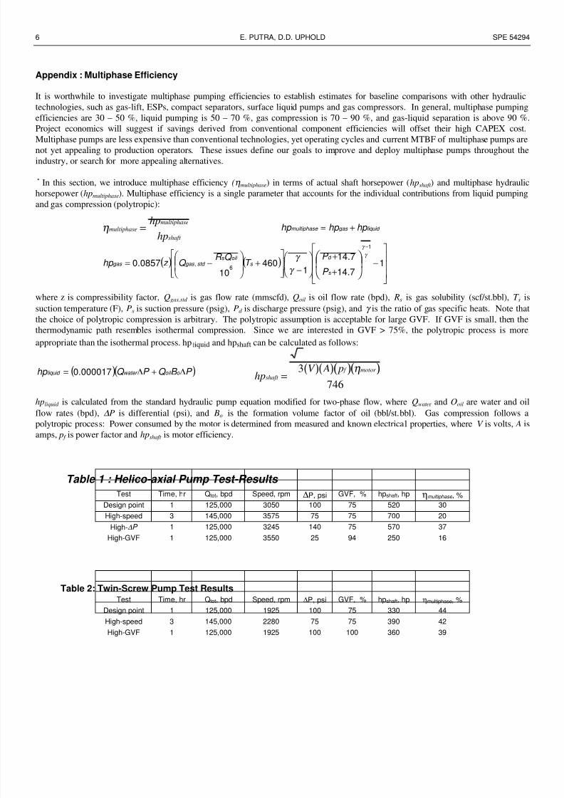
Appendix : Multiphase Efficiency
It is worthwhile to investigate multiphase pumping efficiencies to establish estimates for baseline comparisons with other hydraulic
technologies, such as gas-lift, ESPs, compact separators, surface liquid pumps and gas compressors. In general, multiphase pumping
efficiencies are 30 – 50 %, liquid pumping is 50 – 70 %, gas compression is 70 – 90 %, and gas-liquid separation is above 90 %
Project economics will suggest if savings derived from conventional component efficiencies will offset their high CAPEX cost.
Multiphase pumps are less expensive than conventional technologies, yet operating cycles and current MTBF of multiphase pumps arenot yet appealing to production operators. These issues define our goals to improve and deploy multiphase pumps throughout the
industry, or search for more appealing alternatives.
˚ In this section, we introduce multiphase efficiency (ηmultiphase) in terms of actual shaft horsepower (hpshaft ) and multiphase hydraulic
horsepower (hpmultiphase). Multiphase efficiency is a single parameter that accounts for the individual contributions from liquid pumping
and gas compression (polytropic):
where z is compressibility factor, Qgas,std is gas flow rate (mmscfd), Qoil is oil flow rate (bpd), Rs is gas solubility (scf/st.bbl), T s is
suction temperature (F), Ps is suction pressure (psig), Pd is discharge pressure (psig), and γ is the ratio of gas specific heats. Note tha
the choice of polytropic compression is arbitrary. The polytropic assumption is acceptable for large GVF. If GVF is small, then the
thermodynamic path resembles isothermal compression. Since we are interested in GVF > 75%, the polytropic process is more
appropriate than the isothermal process. hpliquid and hpshaft can be calculated as follows:
hpliquid is calculated from the standard hydraulic pump equation modified for two-phase flow, where Qwater and Ooil are water and oi
flow rates (bpd), ∆P is differential (psi), and Bo is the formation volume factor of oil (bbl/st.bbl). Gas compression follows a
polytropic process: Power consumed by the motor is determined from measured and known electrical properties, where V is volts, A is
amps, p f is power factor and hpshaft is motor efficiency.
Table 1 : Helico-axial Pump Test-Results
Test Time, hr Qtot, bpd Speed, rpm ∆P, psi GVF, % hpshaft, hp ηmultiphase , %
Design point 1 125,000 3050 100 75 520 30
High-speed 3 145,000 3575 75 75 700 20
High-∆P 1 125,000 3245 140 75 570 37
High-GVF 1 125,000 3550 25 94 250 16
Table 2: Twin-Screw Pump Test ResultsTest Time, hr Qtot, bpd Speed, rpm ∆P, psi GVF, % hpshaft, hp ηmultiphase, %
Design point 1 125,000 1925 100 75 330 44
High-speed 3 145,000 2280 75 75 390 42
High-GVF 1 125,000 1925 100 100 360 39
ηmultiphasemultiphase
shaft
hp
hp=
( )( )P B Q P Q hp o oil water liquid ∆+∆= 000017.0 ( )( )( )( )hp
V A pshaft
f motor
=3
746
η
liquid gas multiphase hp hp hp +=
( ) ( )
−+
+
−
+
−=
−
17.14
7.14
1460
100857.0
1
6,
s
d s
oil s std gas gas
P
P T
Q R Q z hp
γ
γ
γ
γ

8/13/2019 Multhiphase Pumps for Minas LOSF.pdf
http://slidepdf.com/reader/full/multhiphase-pumps-for-minas-losfpdf 7/10
SPE 54294 MULTIPHASE PUMPS FOR MINAS LIGHT OIL STEAM FLOOD, SUMATRA-INDONESIA 7
_____________________________________________________________________________________________
Figure 1 : Helico-axial Pump Diagrams
Figure 2 : Details of a Helico-axial Pump Stage
Rotating flow impeller
Stationary diffuser

8/13/2019 Multhiphase Pumps for Minas LOSF.pdf
http://slidepdf.com/reader/full/multhiphase-pumps-for-minas-losfpdf 8/10
8 E. PUTRA, D.D. UPHOLD SPE 54294 _________________________________________________________________________________________________________
****
* *****
****
*
**
*** **
****
** *
****
High-pressure test
Design-point test
High-speed test
Figure 3: Twin-screw Pump Diagrams
Figure 4 : Pump Manufacturer’s Curve and Test-Points Loci - Helico-Axial Pump

8/13/2019 Multhiphase Pumps for Minas LOSF.pdf
http://slidepdf.com/reader/full/multhiphase-pumps-for-minas-losfpdf 9/10
SPE 54294 MULTIPHASE PUMPS FOR MINAS LIGHT OIL STEAM FLOOD, SUMATRA-INDONESIA 9
_____________________________________________________________________________________________
Figure 5 : Differential Pressure vs. Multiphase Efficiencyat Various Speeds - Helico-Axial Pump
Figure 6 : Total Flow Rate vs. Differential Pressureat Various RPM - Helico-Axial Pump
Figure 7 : Total Flow Rate vs. Differential Pressureat various GVF – Helico-axial Pump

8/13/2019 Multhiphase Pumps for Minas LOSF.pdf
http://slidepdf.com/reader/full/multhiphase-pumps-for-minas-losfpdf 10/10
10 E. PUTRA, D.D. UPHOLD SPE 54294 _________________________________________________________________________________________________________
Figure 8 : Differential Pressure vs. Total Flow Rate – Twin-Screw Pump
Figure 9 : Differential Pressure vs. Multiphase Efficiency – Twin-Screw Pump
Figure 10 : Pump Speed vs. Total Flow Rate – Twin Screw Pump