mtweb.mtsu.edumtweb.mtsu.edu/nchong/electrochemistry-6230b.pdf · 2011-03-02mtweb.mtsu.edu
TRANSCRIPT

METHOD MEASUREMENT PRINCIPLEAPPLICATIONS
QUALIT-ATIVEINFORM-ATION
DESIREDMINIMUMSAMPLESIZE
DETECTIONLIMIT
COMMENTS
Voltammetry(Polarography)(amperometrictitrations)(chronoamperometry)
Current as a function ofvoltage at a polarizedelectrode
Quantitative analysis ofelectrochemicallyreducible organic orinorganic material
Reversibility ofreaction
100 mg 10-1-10 –3 ppm
10 mg
A large number of voltageprograms may be used.Pulse Polarography andDifferential PulsePolarography improvedetection limits.
Potentiometry(potentiometrictitration)(chronopotentiometry)
Potential at 0 current Quantitative analysis ofions in solutions, pH.
Defined byelectrode (e.g.,F-, Cl-, Ca2+)
100 mg 10-2 -102 ppm Measures activity rather thanconcentration.
Conductimetry(conductometrictitrations)
Resistance orconductance at inertelectrodes
Quantification of anionized species, titrations
Little qualitativeidentificationinformation
100 mg Commonly used as adetector for ionchromatography.
Coulometry Current and time asnumber of Faradays
Exhaustive electrolysis Little qualitativeidentificationinformation
100 mg 10-9 -1 g High precision possible.
Anodic StrippingVoltammetry(Electrodeposition)
Weight Quantitative traceanalysis ofelectrochemicallyreducible metals thatform amalgams withmercury
Oxidationpotential permitsidentification ofmetal.
100 mg 10-3 -103 g
10 ng
Electrodeposition stepprovides improved detectionlimits over normalvoltammetry.
Comparison of Various Electrochemical Methods

Electrodes and Potentiometry
Introduction
1.) Potentiometry Use of electrodes to measure voltages to provide chemical information
(concentration, activity, charge)- Various electrodes have been designed to respond selectively to specific analytes
Use a Galvanic Cell- Unknown solution becomes a ½-cell- Add electrode that transfers/accepts
electrons from unknown analyte- Connect unknown solution by salt
bridge to second ½-cell at fixedcomposition and potential
Indicator Electrode: electrode thatresponds to analyte and donates/acceptselectrons
Reference Electrode: second ½ cell at aconstant potential
Cell voltage is difference between theindicator and reference electrode

Binding generates
potential difference.
Electrodes and Potentiometry
Introduction
2.) Example A Heparin Sensor
- Voltage response is proportional to heparin concentration in blood- Sensor is selective for heparin
Negatively charged heparinbinds selectively to positivelycharged membrane.
heparin
Potential isproportional to
[heparin]

Electrodes and PotentiometryAll potentiometric measurements requires the use of a reference electrodeas one of the half-cell potential.
1.) Overview Potential change only dependent on one ½ cell concentrations Reference electrode is fixed or saturated doesn’t change!
Reference electrode,[Cl-] is constant
Potential of the cellonly depends on
[Fe2+] & [Fe3+]
Pt wire is indicatorelectrode whosepotential respondsto [Fe2+]/[Fe3+]
]Cllog[..]Fe[
]Fe[log
..Ecell
0591602220
1
0591607710
3
2
Unknown solution of[Fe2+] & [Fe3+]
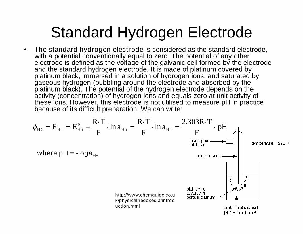
Standard Hydrogen Electrode• The standard hydrogen electrode is considered as the standard electrode,
with a potential conventionally equal to zero. The potential of any otherelectrode is defined as the voltage of the galvanic cell formed by the electrodeand the standard hydrogen electrode. It is made of platinum covered byplatinum black, immersed in a solution of hydrogen ions, and saturated bygaseous hydrogen (bubbling around the electrode and absorbed by theplatinum black). The potential of the hydrogen electrode depends on theactivity (concentration) of hydrogen ions and equals zero at unit activity ofthese ions. However, this electrode is not utilised to measure pH in practicebecause of its difficult preparation. We can write:
where pH = -logaH+
http://www.chemguide.co.uk/physical/redoxeqia/introduction.html
pHF
TRa
F
TRa
F
TREE HH
oHHH
303.2lnln2

Electrodes and Potentiometry
Common Reference Electrodes
2.) Silver-Silver Chloride Reference Electrode
Convenient- Common problem is porous plug becomes clogged
Eo = +0.222 V
Activity of Cl- not 1E(sat,KCl) = +0.197 V

Electrodes and Potentiometry
Common Reference Electrodes
3.) Saturated Calomel Reference Electrode (S.C.E)
Saturated KCl maintains constant [Cl-] even withsome evaporation
Standard hydrogen electrodes are cumbersome- Requires H2 gas and freshly prepared Pt surface
Eo = +0.268 V
Activity of Cl- not 1E(sat,KCl) = +0.241 V

Electrodes and Potentiometry
Relationships among the Three Reference Electrodes
4.) Observed Voltage is Reference Electrode Dependant The observed potential depends on the choice of reference electrode
- Silver-silver chloride and calomel have different potentials
Use Reference Scale to convert between Reference Electrodes
Observed potential relative to SCEObserved potential relative to Ag|AgCl
Observed potential relative to SHE

9
Two-solution electrochemical cell
Cathode: reduction of OAnode: oxidation of H
H2 ↔ 2H+ + 2e H2O + ½O2 + 2e ↔ 2OH-
electrode (half-cell )reaction:
electrode (half-cell )reaction:
• gases are held in a piston-cylinder for constant pressure
H+ and OH- ions recombine or H2O dissociates: OH- + H+ ↔H2O(L) (maintains charge neutrality)
• electrons released or consumed at the electrodes
• electrons move to or from electrodes via an external circuit
• a device is inserted in the circuit to utilize/control e flow

10
(a) Open circuitDH of the reaction H2 +½O2 H2O isdissipated as heat.
• H+ and OH- recombine in thebridge
(b) battery or Galvanic cell
DG of the reaction isconverted to useful work
Otherwise the same as (a)

11
• potentiometer blocks currentbetween half cells
• The voltage is the electromotiveforce, or emf
• the emf provides information on thefree energy of the overall reaction
• applied voltage overcomes theequilibrium emf
• e flow in the direction oppositeto modes (a) & (b)
• water is decomposed into H2 andO2
• external work required
equilibrium
e≠0

12
• At true equilibrium: e = 0 and DG = 0;equilibrium condition same as chemicalthermo.
I = chemical potential of aqueous ionsVi = stoichiometric coefficients
cion = ion concentration in moles per liter (molarity, M)
• when all species are in “standard states”
Go = -nFo
zFGlhs
iirhs
ii

Indicator Electrodes
• Inert:Pt, Au, Carbon. Don’t participate in thereaction.
example: SCE || Fe3+, Fe2+(aq) | Pt(s)
• Certain metallic electrodes: detect their ions(Hg, Cu, Zn, Cd, Ag)example SCE || Ag+(aq) | Ag(s)Ag+ + e- Ag(s)
E0+= 0.799VHg2Cl2 + 2e 2Hg(l) + 2Cl-
E-= 0.241V
E = 0.799 + 0.05916 log [Ag+] - 0.241 V

14
Standard electrode potential• measured in a special full electrochemical cell:
- On one side: the desired half-cell reaction
- On the other side: the standard hydrogen electrode, or SHE
- In both: all concs = 1 M; all pressures = 1 atm
Half-cell Reaction o, Volts
1. H2O = ½O2 + 2H+ + 2e -1.229
2. 2OH- = ½O2 + H2O + 2e -0.401
3. H2 = 2H+ + 2e 0
Gases reference
4. Au = Au3+ + 3e -1.498
5. Cu = Cu2+ + 2e -0.337
6. Ni = Ni2+ + 2e 0.250
7. Fe = Fe2+ + 2e 0.440
8. Na = Na+ + e 2.714
metals
noble metal
active metal

15
2
2PuO
9. Fe2+ = Fe3+ + e -0.771
10. U4+ + 2H2O = + 4H+ + 2e -0.338
11. Pu4+ + 2H2O = + 4H+ + 2e -1.043
12. Pu3+ = Pu4+ + e -0.98
13. Cu+ = Cu2+ + e -0.16
2
2UOonly ions
2
2UO14. UO2(s) = + 2e 0.43
15. Fe(s) + H2O = FeO(s) + 2H+ + 2e 0.03
16. 2Cu(s) + 2OH- = Cu2O(s) + H2O + 2e 0.36
17. Cu(s) + 2OH- = Cu(OH)2(s) + 2e 0.22
solid oxides orhydroxides
generic half-cell reaction: reduced form = oxidized form + ze
reduced
oxidizedoii
c
c
nlog
059.0
2.3R(298)/
Number of electrons transferred
Nernstpotential

16
Fe2+ + Pu4+ = Fe3+ + Pu3+
Fe2+ = Fe3+ + e 23 FeFe
oFeFe C/Clog059.0
Pu3+ = Pu4+ + e 34 PuPu
oPuPu C/Clog059.0
360010
10cc
ccK
059.0/)98.0(77.0
059.0/εε
PuFe
PuFeoPu
oFe
42
33
Species Initial moles Final moles Final conc (M)
Pu3+ 0 /2
Pu4+ 0.5 0.5 - 0.25 - /2
Fe2+ 1.0 1.0 - 0.5 - /2
Fe3+ 0 /2

Electrodes and Potentiometry
Junction Potential
1.) Occurs Whenever Dissimilar Electrolyte Solutions are in Contact Develops at solution interface (salt bridge) Small potential (few millivolts) Junction potential puts a fundamental limitation on the accuracy of direct
potentiometric measurements- Don’t know contribution to the measured voltage
Again, an electric potential is generated by a separation of charge
Different ion mobility resultsin separation in charge

Electrodes and Potentiometry
Indicator Electrodes
1.) Two Broad Classes of Indicator Electrodes Metal Electrodes
- Develop an electric potential in response to a redox reaction at the metalsurface
Ion-selective Electrodes- Selectively bind one type of ion to a membrane to generate an electric
potential
Remember an electric potential is generated by a separation of charge

Voltage of Galvanic Cell
The equation, which expresses the voltage of agalvanic cell, is called the Nernst equation. If B, D,E, F are individual components of the reactionmixture, b, d, e, f are stoichiometric coefficients ofthe reaction and U° the standard EMF (voltage) ofthe cell then:
When the reagents are in standard state (a = 1), then U= U°.
U UR T
z F
a a
a aE
e
F
f
B
b
D
d
0 ln

Concentration cell
• The concentration cell is formed by two electrodesmade of the same metal which are immersed in solutionof respective ions of different activity (concentration) a1
and a2. Considering the Nernst equation, the standardvoltage is equal to zero and the second term is simplified(the activities of metals are identical). Then:
UR T
F
a
a
ln 2
1

Calomel electrode
• The calomel electrode is together with the silver chloride electrodethe most important electrode of the 2nd kind. It is used as referenceelectrode in the determination of potentials of other electrodes. It ismade of mercury covered by the calomel layer (Hg2Cl2) and KClsolution. The potential of this electrode is given by the equilibriumconcentration of Cl- anions in the electrode reaction:
• Hg2Cl2(s) + 2 e- = 2 Hg(l) + 2 Cl-
• This equilibrium is also influenced by concentration of KCl.Saturated calomel electrode is usually prepared – solution of KClis saturated. It is easy to prepare and its potential is reproducibleand very stable.
http://www.resonancepub.com/electrochem.htm

Glass electrode
• The glass electrode is an ion selective electrode used in thedetermination of pH. Its main part is a silver chloride electrode(4) placed in medium of known pH, e.g. in solution of NaCl (2).This solution is separated from a solution with unknown pH by athin glass membrane (1). It forms a concentration cell thepotential of which is given by the activities (concentrations) ofhydrogen ions on either side of the membrane, and is partlyinfluenced by alkaline ions present both in the glass andmeasured solution. For the surface potential of the glassmembrane we can write:
• E = Eo - 0,059 pH [V],• where Eo is a characteristic electrode constant. The voltage on
the glass electrode is measured by electronic voltmeters whichdisplay directly the pH values. These instruments are called pH-meters. As a reference electrode (6), the silver chloride orcalomel electrode surrounded by 0.1 M HCl solution is usuallyused. Both electrodes often form an integral immersion body (5).(7) is a porous junction to the measured solution. Modified pH-electrodes can be used directly for pH measurement in blood,gastric juice etc. Microelectrodes can be used directly for pHmeasurement inside cells.
http://commons.wikimedia.org/wiki/Image:Glass_electrode_scheme.jpg

Electrodes and Potentiometry
Indicator Electrodes
2.) Metal Electrodes Platinum
- Most common metal indicator electrode- Inert: does not participate in many chemical reactions- Simply used to transmit electrons
Other electrodes include Gold and Carbon Metals (Ag, Cu, Zn, Cd, Hg) can be used to monitor their aqueous ions
- Most metals are not useable- Equilibrium not readily established at the metal surface
E+o = +799 V
E(sat,KCl) = +0.241 V
½ Reaction at Ag indicator electrode:
½ Reaction at Calomel reference electrode:
24101
1
0591607990 .
]Ag[log
..EEEcell
Potential of Agindicator electrode
Cell voltage changes as a function of [Ag+]
Example:
Cell Potential from Nernst Equation:

Electrodes and Potentiometry
Indicator Electrodes
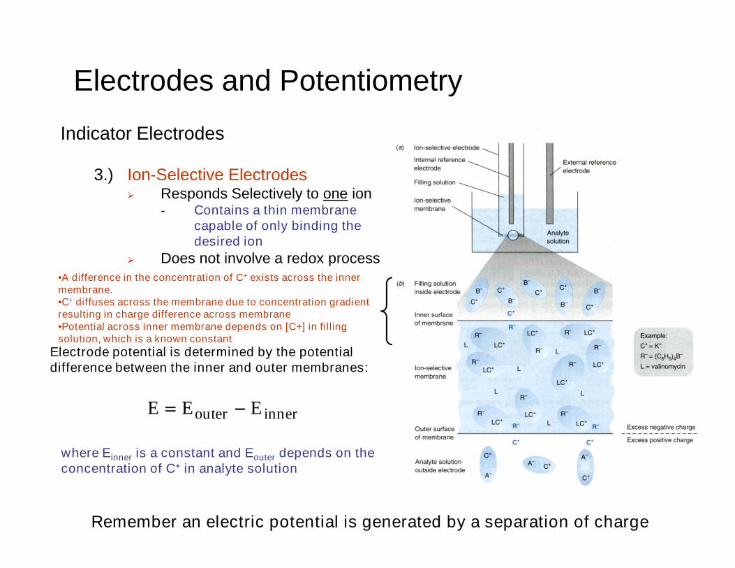
3.) Ion-Selective Electrodes Responds Selectively to one ion
- Contains a thin membranecapable of only binding thedesired ion
Does not involve a redox process
Membrane contains a ligand (L) thatspecifically and tightly binds analyteof interest (C+)
The counter-ions (R-,A-) can’t cross themembrane and/or have low solubility inmembrane or analyte solution
Remember an electric potential is generated by a separation of charge
•Potential across outer membrane depends on [C+] inanalyte solution•A difference in the concentration of C+ exists across theouter membrane.•C+ diffuses across the membrane due to concentrationgradient resulting in charge difference across membrane
Electrodes and Potentiometry
Indicator Electrodes
3.) Ion-Selective Electrodes Responds Selectively to one ion
- Contains a thin membranecapable of only binding thedesired ion
Does not involve a redox process
Remember an electric potential is generated by a separation of charge
•A difference in the concentration of C+ exists across the innermembrane.•C+ diffuses across the membrane due to concentration gradientresulting in charge difference across membrane•Potential across inner membrane depends on [C+] in fillingsolution, which is a known constant
innerouter EEE
Electrode potential is determined by the potentialdifference between the inner and outer membranes:
where Einner is a constant and Eouter depends on theconcentration of C+ in analyte solution

][constant Clogn
.E
059160
Electrodes and Potentiometry
Indicator Electrodes
4.) Ion-Selective Electrodes Responds Selectively to one ion
- Contains a thin membranecapable of only binding thedesired ion
Does not involve a redox process
Electrode Potential is defined as:
where [C+] is actually the activity of the analyte andn is the charge of the analyte

Electrodes and Potentiometry
pH Electrodes
1.) pH Measurement with a Glass Electrode Glass electrode is the most common ion-selective electrode Combination electrode incorporates both glass and
reference electrode in one body
Ag(s)|AgCl(s)|Cl-(aq)||H+(aq,outside) H+(aq,inside),Cl-(aq)|AgCl(s)|Ag(s)
Outer referenceelectrode
[H+] outside(analyte solution)
[H+] inside Inner referenceelectrode
Glass membraneSelectively binds H+
Electric potential is generated by [H+] difference across glass membrane

Electrodes and Potentiometry
pH Electrodes
2.) Glass Membrane Irregular structure of silicate lattice
Cations (Na+) bindoxygen in SiO4 structure

Electrodes and Potentiometry
pH Electrodes
2.) Glass Membrane Two surfaces of glass “swell” as they absorb water
- Surfaces are in contact with [H+]

Electrodes and Potentiometry
pH Electrodes
2.) Glass Membrane H+ diffuse into glass membrane and replace Na+ in hydrated gel region
- Ion-exchange equilibrium- Selective for H+ because H+ is only ion that binds significantly to the
hydrated gel layer
H(0.05916)constant pE
Charge is slowly carriedby migration of Na+
across glass membrane
Potential is determinedby external [H+]
Constant and b are measured when electrode is calibrated with solution of known pH

Electrodes and Potentiometry
pH Electrodes
3.) Calibration A pH electrode should be calibrated with two or more standard buffers
before use. pH of the unknown should lie within the range of the standard buffers
Measured voltage is correlatedwith a pH, which is then used tomeasure an unknown.

Electrodes and Potentiometry
pH Electrodes
4.) Errors in pH Measurements Standards
- pH measurements cannot be more accurate than standards (±0.01)
Junction potential- If ionic strengths differ between analyte and standard buffer, junction potential
will differ resulting in an error of ±0.01
Junction Potential Drift- Caused by slow changes in [KCl] and [AgCl] re-calibrate!
Sodium Error- At very low [H+], electrode responds to Na+ and the apparent pH is lower than
the true pH
Acid Error- At high [H+], the measured pH is higher than actual pH, glass is saturated
Equilibration Time- Takes ~30s to minutes for electrode to equilibrate with solution
Hydration of glass- A dry electrode will not respond to H+ correctly
Temperature- Calibration needs to be done at same temperature of measurement
Cleaning- Contaminates on probe will cause reading to drift until properly cleaned or
equilibrated with analyte solution

Electrodes and Potentiometry
pH Electrodes
4.) Errors in pH Measurements pH measurements are accurate to ± 0.02 pH units
Larger errors occur at highand low pH readings

Ion selective electrodes (ISEs)
A difference in the activity of an ion on eitherside of a selective membrane results in athermodynamic potential difference being
created across that membrane
Ca2 + Ca2 +0 .01 M Ca2 +
0 .0 2 M Cl -
0 .1 M Ca2 +
0 .2 M Cl -
( 0 . 1 + ) M Ca2 +( 0 . 1 - ) M Ca2 +
0 .0 2 M Cl - 0 .2 M Cl -
+
+
+
+
-
-
-
-
Calcium selectivemolecularrecognition ligand

ISEs
25C)(@
log0592.0
ln
ln
2
1
2
1
2
1
A
A
nA
A
nF
RTE
nFEA
ARTG

Electrodes and Potentiometry
Other Ion-Selective Electrodes
1.) Solid-State Electrode Based on an inorganic crystal
- Fluoride electrode: LaF3 crystal doped with Eu2+
F- migrates across crystal by “jumping”into crystal vacancies caused by Eu2+
Potential caused by charge imbalance from migrating ion across membrane
F(0.05916)constant pE

Electrodes and Potentiometry
Other Ion-Selective Electrodes
2.) Liquid-Based Ion-Selective Electrodes Similar to solid-state electrode
- Hydrophobic membrane impregnated with hydrophobic ion exchanger- Hydrophobic ion exchanger selective for analyte ion
2pCaE )2
0.05916(constant
Binds Ca+2 Hydrophobic solventHydrophobic counter-ion

Electrodes and Potentiometry
Other Ion-Selective Electrodes
2.) Liquid-Based Ion-SelectiveElectrodes
Remember: ion-selective electrodescreate a potential from a chargeimbalance caused by analyte ionmigration across membrane

Electrodes and Potentiometry
Other Ion-Selective Electrodes
3.) Compound Electrodes Conventional electrode surrounded by a membrane that isolates or generates
the analyte to which the electrode responds
pH electrode surrounded by membranepermeable to CO2.
As CO2 passes through membrane anddissolves in solution, pH changes.
pH change is an indirect measure of CO2
concentration

Electrodes and Potentiometry
Other Ion-Selective Electrodes
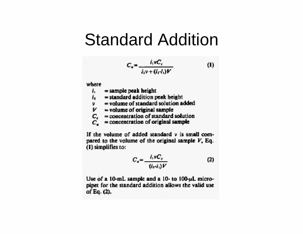
4.) Standard Addition Corrects for analyte dissolved in complex or unknown matrix
- Blood, urine, biomass, etc
Procedure:1. Measure potential for unknown analyte solution2. Add small (known) volume of a standard solution3. Measure new potential4. Repeat and graph data
ssS/k
xoS/kS/E
so VccV)VV( 101010
y b m x
where:Vo is the initial volumeVs is the added volumeE is the measured potentialcx is the unknown concentrationcs is the standard concentrations is a constant (bRT/nF)ln10

Other Ion-Selective Electrodes
4.) Standard Addition Corrects for analyte dissolved in complex or unknown matrix
- Blood, urine, biomass, etc
Procedure:5. x-intercept yields the unknown (cx) concentration
Electrodes and Potentiometry
s
xo
c
cV
m
bx intercept
Only unknown

Liquid Membrane Electrodes
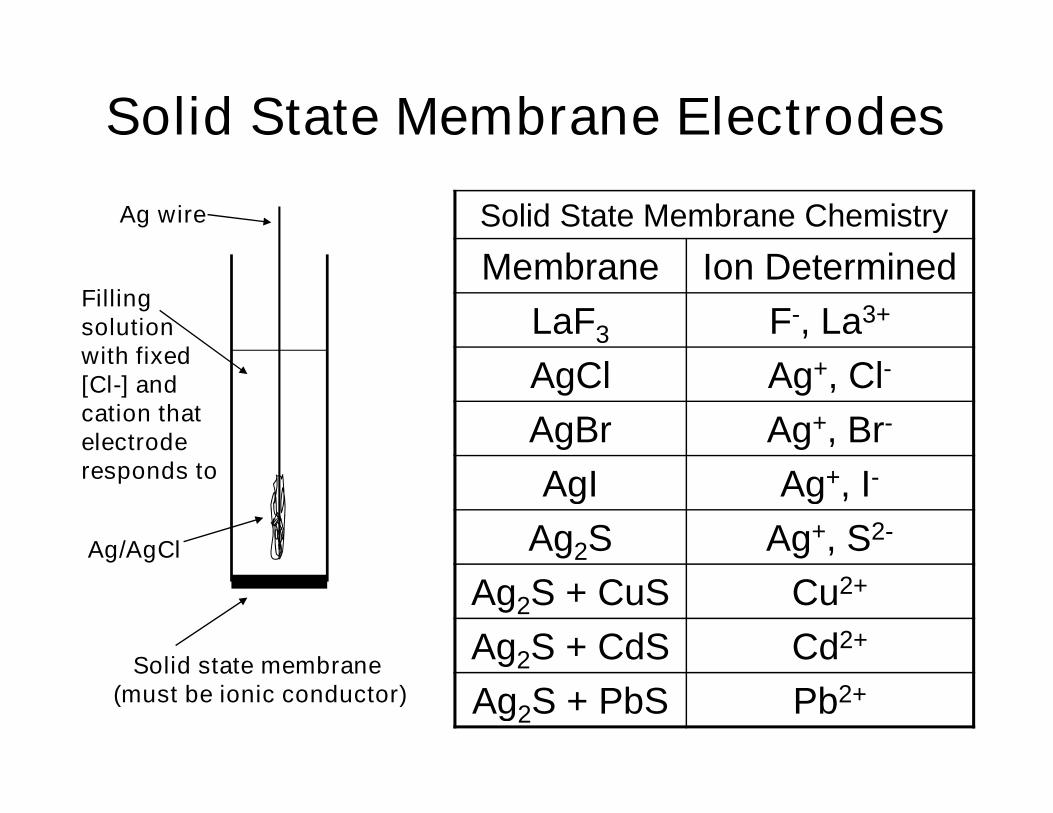
Solid State Membrane Electrodes
Ag wire
Fillingsolutionwith fixed[Cl-] andcation thatelectroderesponds to
Ag/AgCl
Solid state membrane(must be ionic conductor)
Solid State Membrane Chemistry
Membrane Ion Determined
LaF3 F-, La3+
AgCl Ag+, Cl-
AgBr Ag+, Br-
AgI Ag+, I-
Ag2S Ag+, S2-
Ag2S + CuS Cu2+
Ag2S + CdS Cd2+
Ag2S + PbS Pb2+

Solid state electrodes

Voltammetry• Voltammetry techniques measure current
as a function of applied potential underconditions that promote polarization of aworking electrode
• Polarography: Invented by J. Heyrovsky(Nobel Prize 1959). Differs fromvoltammetry in that it employs a droppingmercury electrode (DME) to continuouslyrenew the electrode surface.
• Amperometry: current proportional toanalyte concentration is monitored at afixed potential

Applications• Handles high salt concentrations better than
chromatographic instrumentation
• Can differentiate between ionic species
– Example: Cr6+ Cr3+
• Ultra Trace range metals (sub-ppb)
• Wastewater Analysis
• Industrial Water/Liquor Analysis
• Pharmaceutics
• Environmental Studies
• Biological/Biochemical Analysis
• Plating Analysis

Polarization
• Some electrochemical cells have significantcurrents.– Electricity within a cell is carried by ion motion
– When small currents are involved, E = IR holds
– R depends on the nature of the solution (next slide)
• When current in a cell is large, the actualpotential usually differs from that calculatedat equilibrium using the Nernst equation– This difference arises from polarization effects
– The difference usually reduces the voltage of a galvaniccell or increases the voltage consumed by an electrolyticcell

Ohmic Potential and the IR Drop
• To create current in a cell, a driving voltageis needed to overcome the resistance of ionsto move towards the anode and cathode
• This force follows Ohm’s law, and isgoverned by the resistance of the cell:
IREEE leftrightcell
Electrodes
IR Drop

Overvoltage and Polarization Sources
• Overvoltage: the difference between theequilibrium potential and the actual potential
• Sources of polarization in cells:
– Concentration polarization: rate of transport toelectrode is insufficient to maintain current
– Charge-transfer (kinetic) polarization:magnitude of current is limited by the rate of theelectrode reaction(s) (the rate of electrontransfer between the reactants and theelectrodes)
– Other effects (e.g. adsorption/desorption)

Steps in an electron transfer eventO must be successfullytransported from bulk solution(mass transport)O must adsorb transiently ontoelectrode surface (non-faradaic)CT must occur between electrodeand O (faradaic)R must desorb from electrodesurface (non-faradaic)R must be transported away fromelectrode surface back into bulksolution (mass transport)

Mass Transport or MassTransfer
• Migration – movement of a charged particle in a potentialfield
• Diffusion – movement due to a concentration gradient. Ifelectrochemical reaction depletes (or produces) somespecies at the electrode surface, then a concentrationgradient develops and the electroactive species will tendto diffuse from the bulk solution to the electrode (or fromthe electrode out into the bulk solution)
• Convection – mass transfer due to stirring. Achieved bysome form of mechanical movement of the solution orthe electrode i.e., stir solution, rotate or vibrate electrodeDifficult to get perfect reproducibility with stirring, betterto move the electrodeConvection is considerably more efficient than diffusionor migration = higher currents for a given concentration =greater analytical sensitivity

Nernst-Planck Equation
x
x
x
RT
F
x
xx CCD
zCDJ iii
ii
ii
Diffusion Migration Convection
Ji(x) = flux of species i at distance x from electrode (mole/cm2 s)Di = diffusion coefficient (cm2/s)Ci(x)/x = concentration gradient at distance x from electrode(x)/x = potential gradient at distance x from electrode(x) = velocity at which species i moves (cm/s)

Diffusion
Fick’s 1st Law
Solving Fick’s Lawsfor particularapplications likeelectrochemistryinvolves establishingInitial Conditions andBoundary Conditions
I = nFAJ

Simplest ExperimentChronoamperometry
time
i

Recall-Double layer

Double-Layer charging
• Charging/discharging a capacitor uponapplication of a potential step
RCtc e
R
EI /
Itotal = Ic + IF

Working electrode choice
• Depends upon potential window desired
– Overpotential
– Stability of material
– Conductivity
– contamination

Working Electrode (cont)
• Rotating Disk Electrode (RDE)
– Ultra Trace Graphite
– Gold
– Glassy Carbon*
• Many other types of WE

Auxiliary Electrode (AE) andReference Electrode (RE)
• AE completes the circuit between thepotentiostat and the WE
• Two different types available
– Platinum
– Glassy Carbon
• RE provides a reference potential to theWE/AE circuit
• Two types of RE
– Ag/AgCl in KCl
– Hg/HgCl in saturated KCl

• Renewable surface• Potential window expanded for reduction (high overpotential forproton reduction at mercury)
Polarography with a Dropping Mercury Electrode

PolarographyA = 4p(3mt/4pd)2/3 = 0.85(mt)2/3
Mass flow rate ofdrop
Density ofdrop
We can substitute this into Cottrell Equation
i(t) = nFACD1/2/ 1/2t1/2
Giving the Ilkovich Equation:
id = 708nD1/2m2/3t1/6C
I has units of Amps when D is in cm2s-1,m is in g/s and t is inseconds. C is in mol/cm3
This expression gives the current at the end of the drop life. The averagecurrent is obtained by integrating the current over this time period
iav = 607nD1/2m2/3t1/6C
We also replace D by 7/3D to account for the compression of the diffusionlayer by the expanding drop

Polarogram
E1/2 = E0 + RT/nF log (DR/Do)1/2
(reversible couple)
Usually D’s are similar so halfwave potential is similar toformal potential. Also potentialis independent of concentrationand can therefore be used as adiagnostic of identity of analytes.
If an electroactive species is capable of undergoing a redox processat the DME, then an S-shaped current-potential trace (a polarographicwave) is usually observed


Other types of Polarography
• Examples refer to polarography but are applicable to othervotammetric methods as well
• all attempt to improve signal to noise
• usually by removing capacitive currents

Normal Pulse Polarography
•current measured at a single instant in the lifetime of each drop.
•higher signal because there is more electroactive species aroundeach drop of mercury.
•somewhat more sensitive than DC polarography.
•data obtained have the same shape as a regular DCP.

NPP advantage
• IL = nFAD1/2c/(ptm)1/2
• (tm = current sampling t)
• IL,N.P./IL,D.C. = (3t/7tm)1/2
• Predicts that N.P.P.
5-10 X sensitive than D.C.P.

Differential pulse voltammetry

Diffrential PulsePolarography (DPP)
• current measured twice during the lifetime of each drop
difference in current is plotted.
• Results in a peak-shaped feature, where the top of the peakcorresponds to E1/2, and the height gives concentration
• This shape is the derivative of the regular DC data.
• DPP has the advantage of sensitive detection limits anddiscrimination against background currents. Traditionally,metals in the ppm range can be determined with DPP.
• Derivative improves contrast (resolution) betweenoverlapping waves

DPP vs DCP
Ep ~ E1/2 (Ep= E1/2±DE/2)
1
-1
(
cnFAD1/2
m
pt
I
where DE=pulse amplitude
s = exp[(nF/RT)(DE/2)]
Resolution depends on DEW1/2 = 3.52RT/nF when DE0
Improved responsebecause charging currentis subtracted and adsorptiveeffects are discriminated against.l.o.d. 10-8M

Resolution

Stripping Voltammetry
• Preconcentration technique.
1. Preconcentration or accumulation step. Here the analyte speciesis collected onto/into the working electrode
2. Measurement step : here a potential waveform is applied to theelectrode to remove (strip) the accumulated analyte.

Deposition potential

ASV

ASV or CSV

Adsorptive StrippingVoltammetry
• Use a chelatingligand thatadsorbs to theWE.
• Can detect byredox process ofmetal or ligand.

Working Electrode
• The working electrode is used to show theresponse of the analyte to the potential
• Mercury Electrode
– Hanging Drop Mercury Electrode (HDME)• Used in the ppb to low ppm range
– Static Drop Mercury Electrode (SDME)• Used in the low ppm range
– Dropping Mercury Electrode (DME)• Used in the ppm range


Multi-Element
Standard Addition

Linear Sweep Voltammetry• Linear sweep voltammetry (LSV) is performed by applying
a linear potential ramp in the same manner as DCP.
• However, with LSV the potential scan rate is usually muchfaster than with DCP.
• When the reduction potential of the analyte is approached,the current begins to flow.
– The current increases in response to the increasingpotential.
– However, as the reduction proceeds, a diffusion layer isformed and the rate of the electrode reductionbecomes diffusion limited. At this point the currentslowly declines.
• The result is the asymmetric peak-shaped I-E curve

The Linear Sweep Voltammogram• A linear sweep
voltammogram for thefollowing reduction of “A”into a product “P” isshown
A + n e- P
• The half-wave potentialE1/2 is often used forqualitative analysis
• The limiting current isproportional to analyteconcentration and isused for quantitativeanalysis
Half-wave potential
A + n e- P
Limiting current
Remember, E is scannedlinearly to higher valuesas a function of time in
linear sweepvoltammetry
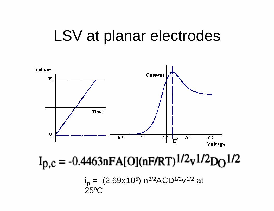
LSV at planar electrodes
ip = -(2.69x10⁵) n3/2ACD1/2v1/2 at25ºC

Hydrodynamic Voltammetry• Hydrodynamic voltammetry is performed
with rapid stirring in a cell
– Electrogenerated species are rapidly sweptaway by the flow
• Reactants are carried to electrodes bymigration in a field, convection, anddiffusion. Mixing takes over and dominatesall of these
– Most importantly, migration rate becomesindependent of applied potential

Hydrodynamic Voltammograms• Example: the
hydrodynamicvoltammogram ofquinone-hydroquinone
• Different waves areobtained dependingon the starting sample
• Both reduction andoxidation waves areseen in a mixture
O
O
quinone hydroquinone
+ 2H+ + 2e
OH
OH
Diagram from Stroebel and Heineman, Chemical Instrumentation, A Systematic Approach 3rd Ed. Wiley 1989.
Anodic wave
Cathodic wave

Oxygen Waves in Hydrodynamic Voltammetry
• Oxygen waves occur inmany voltammetricexperiments– Here, waves from two
electrolytes (no sample!)are shown before andafter sparging/degassing
• Heavily used for analysisof O2 in many types ofsample– In some cases, the
electrode can be dipped inthe sample
– In others, a membrane isneeded to protect theelectrode (Clark sensor)
Diagram from Stroebel and Heineman, Chemical Instrumentation, A Systematic Approach 3rd Ed. Wiley 1989.
The Clark Voltammetric Oxygen Sensor
• Named after its generally recognized inventor (LeylandClark, 1956), originally known as the "Oxygen MembranePolarographic Detector“
• It remains one of the most commonly used devices formeasuring oxygen in the gas phase or, more commonly,dissolved in solution
• The Clark oxygen sensor finds applications in wide areas:– Environmental Studies
– Sewage Treatment
– Fermentation Process
– Medicine

The Clark Voltammetric Oxygen Sensor
dissolvedO2
analyte solution
O2 permeable membrane(O2 crosses via diffusion)
platinum electrode
electrolyte
O2
O2
O2
O2 + 2H2O + 4e- 4OH-
At the platinum cathode:
At the Ag/AgCl anode:
Ag + Cl- AgCl + e-
(-0.6 volts)
id = 4 F Pm A P(O2)/b
id - measured current
F - Faraday's constant
Pm - permeability of O2
A - electrode area
P(O2) - oxygen concentration
b - thickness of the membrane

The Clark Voltammetric Oxygen Sensor
• General design and modern miniaturizedversions :

Hydrodynamic Voltammetry as an LC Detector
• One form of electrochemical LC detector:
Classes of Chemicals Suitable for Electrochemical Detection:
Phenols, Aromatic Amines, Biogenic Amines, Polyamines,Sulfhydryls, Disulfides, Peroxides, Aromatic Nitro Compounds,Aliphatic Nitro Compounds, Thioureas, Amino Acids, Sugars,Carbohydrates, Polyalcohols, Phenothiazines, Oxidase EnzymeSubstrates, Sulfites

Cyclic Voltammetry
• Cyclic voltammetry (CV) is similar to linearsweep voltammetry except that the potentialscans run from the starting potential to theend potential, then reverse from the endpotential back to the starting potential
• CV is one of the most widely usedelectroanalytical methods because of itsability to study and characterize redoxsystems from macroscopic scales down tonanoelectrodes

Cyclic Voltammetry• The waveform, and the resulting I-E curve:
The I-E curve encodesa large amount ofinformation (see nextslide)

Cyclic Voltammetry• A typical CV for a simple
redox system
• CV can rapidly generatea new oxidation state ona forward scan anddetermine its fate on thereverse scan
• Advantages of CV– Controlled rates
– Can determinemechanisms andkinetics of redoxreactions
P. T. Kissinger and W. H. Heineman, J. Chem. Ed. 1983, 60, 702.

CV
E° = (Epa + Epc)/2
DEp = Epa - Epc = 59mV/n

IrreversibleFor irreversible processes peaks are reduced in size and widely separated.Totally irreversible systems are characterized by a shift of the peak potentialwith the scan rate:
Ep = E° - (RT/anaF)[0.78 - ln(ko/(D)1/2) + ln (anaFn/RT)1/2]
where a is the transfer coefficient and na is the number of electrons involvedin the charge-transfer step. Thus, Ep occurs at potentials higher than E°, withthe overpotential related to k° and a.
The peak current, given by:
ip = (2.99x10⁵)n(ana)1/2ACD1/2n1/2
is still proportional to the bulk concentration, but will be lower in height(depending upon the value of a). Assuming a = 0.5, the ratio of the reversible-to-irreversible current peaks is 1.27

Quasi-reversible
For quasi-reversible systems (with 10-1 > k° > 10-5 cm/s)the current is controlled by both the charge transfer andmass transport. The shape of the cyclic voltammogramis a function of the ratio k°/(pnnFD/RT)1/2. As the ratioincreases, the process approaches the reversible case.For small values of it, the system exhibits an irreversiblebehavior. Overall, the voltammograms of a quasi-reversible system are more drawn out and exhibit alarger separation in peak potentials compared to areversible system.

Mechanistic complications part1: The EC mechanism

The ECE mechanism

Catalytic

Spectroelectrochemistry (SEC)• CV and spectroscopy can be combined by using optically-
transparent electrodes
• This allows for analysis of the mechanisms involved incomplex electrochemical reactions
• Example: ferrocene oxidized to ferricinium on a forwardCV sweep (ferricincium shows UV peaks at 252 and 285nm), reduced back to ferrocene (fully reversible)
Y. Dai, G. M. Swain, M. D. Porter, J. Zak, “New horizons in spectroelectrochemical measurements: Optically transparent carbon electrodes,” Anal. Chem., 2008, 80, 14-27.

Coulometric Methods of Analysis
• Potentiometry: Electrochemical cells under staticconditions
• Coulometry, electrogravimetry, voltammetry andamperometry: Electrochemical cells under dynamicmethods (current passes through the cell)
• Coulomteric methods are based on exhaustiveelctrolysis of the analyte: that is quantitativereduction or oxidation of the analyte at the workingelectrode or the analyte reacts quantitatively with areagent generated at the working electrode
• A potential is applied from an external sourceforcing a nonspontaneous chemical reaction to takeplace ( Electrolytic cell)

Types of Coulometry1. Controlled potential coulometry: constant potential
is applied to electrochemical cell
2. Controlled current coulometry: constant current ispassed through the electrochemical cell
Faraday’s law:
Total charge, Q, in coulombs passed duringelectrolysis is related to the absolute amount ofanalyte:
Q = nFN
n = #moles of electrons transferred per mole ofanalyte
F = Faradays constant = 96487 C mol-1
N = number of moles of analyte
Coulomb = C = Ampere X sec = A.s

• For a constant current, i:
Q = ite ; (te = electrolysis time)
• For controlled potential coulometry: the current varieswith time:
Q =
What do we measure in coulometry?
Current and time. Q & N are then calculated according
to one of the above equations
• Coulometry requires 100% current efficiency. Whatdoes this mean?– All the current must result in the analyte’s oxidation or
reduction
ett
tdtti
0)(
Controlled potential coulometry(Potentiostatic coulometry)
• The working electrode will be kept at constantpotential that allows for the analyt’s reductionor oxidation without simultaneously reducingor oxidizing other species in the solution
• The current flowing through the cell isproportional to the analyt’s concnetration
• With time the analyte’s concentration as wellas the current will decrease
• The quantity of electricity is measured with anelectronic integrator.

A.) Introduction:
1.) Coulometry: electrochemical method based on the quantitative oxidation orreduction of analyte
- measure amount of analyte by measuring amount of current andtime
required to complete reaction
charge = current (i) x time in coulombs- electrolytic method external power added to system
2.) Example:- Coulometric Titration of Cl-
- use Ag electrode to produce Ag+
Ag (s) Ag+ + e-
Ag+ + Cl- AgCl (ppt.)
- measure Ag+ in solution by 2nd electrode- only get complete circuit when Ag+ exists in solution- only occurs after all Cl- is consumed- by measuring amount of current and time required
to complete reaction can determine amount of Cl-
Coulometric Methods

4.) Two Types of Coulometric Methodsa) amperostatic (coulmetric titration)
- most common of twob) potentiostatic
Fundamental requirement for both methods is 100% current efficiency- all e- go to participate in the desired electrochemical process- If not, then takes more current over-estimate amount of analyte
B) Amperostatic Methods (Coulometric Titrations)
1.) Basics: titration of analyte in solution by using coulometry at constant currentto generate a known quantity of titrant electrochemically
- potential set by contents of cell- Example:
Ag (s) Ag+ + e-for precipitation titration of Cl-
- To detect endpoint, use 2nd electrode to detect buildup of titrantafter
endpoint.

2.) Applications
a) Can be used for Acid-Base Titrations- Acid titration
2H2O + 2e- 2OH- + H2 titrant generation reaction
- Base titration
H2O 2H+ + ½ O2 + 2e- titrant generation reaction
b.) Can be used for Complexation Titrations (EDTA)
HgNH3Y2- + NH4
+ + 2e- Hg + 2NH3 +HY3-
HY3- H+ + Y4-
c.) Can be used for Redox Titrations
Ce3+ Ce4+ + e-
Ce4+ + Fe2+ Ce3+ + Fe3+

Selecting a Constant Potential
• The potential is selected so that the desired oxidationor reduction reaction goes to completion withoutinterference from redox reactions involving othercomponents of the sample matrix.
Cu2+(aq) + 2e Cu(s)
• This reaction is favored whenthe working electrode'spotential is more negative than+0.342 V.
• To maintain a 100% currentefficiency, the potential mustbe selected so that thereduction of H+ to H2 does notcontribute significantly to thetotal charge passed at theelectrode.

Calculation of the potential needed for quantitative reduction of Cu2+
• Cu2+ would be considered completely reduced when99.99% has been deposited.
• Then the concentration of Cu2+ left would be ≤1X10⁻⁴ [Cu2+ ]0
• If [Cu2+ ]0 was 1X10⁻⁴ Mthen the cathode's potential must be more negative than +0.105 Vversus the SHE (-0.139 V versus the SCE) to achieve a quantitativereduction of Cu2+ to Cu. At this potential H+ will not be reduced to H2
I.e., Current efficiency would be 100%• Actually potential needed for Cu2+ are more negative than +0.105 due
to the overpotential

Minimizing electrolysis time
• Current decreases continuousthroughout electrolysis.
• An exhaustive electrolysis,therefore, may require a longertime
• The current at time t isit = i0 e-kt
• i° is the initial current• k is a constant that isdirectly proportional to the
•area of the working electrode•rate of stirring
and inversely proportional to•volume of the solution.
It = Ioe-kt
k = 25.8 DA/Vdwhere:D = diffusion coefficientA = electrode surface areaV = volumed = thickness of the surface layer whereconcentration gradient exists

• For an exhaustive electrolysis in which 99.99% of theanalyte is oxidized or reduced, the current at the endof the analysis, te, may be approximatedi (10-4)io
Since i = i0 e-kt
te = 1/k ln (1X10⁻⁴) = 9.21/k
• Thus, increasing k leads to a shorter analysis time.• For this reason controlled-potential coulometry is
carried out in– small-volume electrochemical cells,– using electrodes with large surface areas– with high stirring rates.
• A quantitative electrolysis typically requiresapproximately 30-60 min, although shorter or longertimes are possible.

Instrumentation
• A three-electrode potentiostat system is used. Twotypes of working electrodes are commonly used: aPt electrode manufactured from platinum-gauze andfashioned into a cylindrical tube, and an Hg poolelectrode.
• The large overpotential for reducing H+ at mercurymakes it the electrode of choice for analytesrequiring negative potentials. For example,potentials more negative than -1 V versus the SCEare feasible at an Hg electrode (but not at a Ptelectrode), even in very acidic solutions.
• The ease with which mercury is oxidized prevents itsuse at potentials that are positive with respect to theSHE.
• Platinum working electrodes are used when positivepotentials are required.

• The auxiliary electrode, which is often a Pt wire, isseparated by a salt bridge from the solutioncontaining the analyte.
• This is necessary to prevent electrolysis productsgenerated at the auxiliary electrode from reactingwith the analyte and interfering in the analysis.
• A saturated calomel or Ag/AgCI electrode serves asthe reference electrode.
• A means of determining the total charge passedduring electrolysis. One method is to monitor thecurrent as a function of time and determine the areaunder the curve.
• Modern instruments, however, use electronicintegration to monitor charge as a function of time.The total charge can be read directly from a digitalreadout or from a plot of charge versus time

Controlled-Current Coulometry(amperstatic)
• The current is kept constant until an indicatorsignals completion of the analytical reaction.
• The quantity of electricity required to attain the endpoint is calculated from the magnitude of the currentand the time of its passage.
• Controlled-current coulometry, also known asamperostatic coulometry or coulometric titrimetry
– When called coulometric titration, electrons serveas the titrant.
• Controlled-current coulometry, has twoadvantages over controlled-potentialcoulometry.
– First, using a constant current leads to more rapidanalysis since the current does not decrease overtime. Thus, a typical analysis time for controlledcurrent coulometry is less than 10 min, asopposed to approximately 30-60 min forcontrolled-potential coulometry.
– Second, with a constant current the total chargeis simply the product of current and time. Amethod for integrating the current-time curve,therefore, is not necessary.
Experimental problems with constant current coulometry
• Using a constant current does present two importantexperimental problems that must be solved if accurate resultsare to be obtained.
• First, as electrolysis occurs the analyte's concentration and,therefore, the current due to its oxidation or reduction steadilydecreases.– To maintain a constant current the cell potential must
change until another oxidation or reduction reaction canoccur at the working electrode.
– Unless the system is carefully designed, these secondaryreactions will produce a current efficiency of less than100%.
• Second problem is the need for a method of determining whenthe analyte has been exhaustively electrolyzed.– In controlled-potential coulometry this is signaled by a
decrease in the current to a constant background orresidual current.
– In controlled-current coulometry, a constant currentcontinues to flow even when the analyte has beencompletely oxidized or reduced. A suitable means ofdetermining the end-point of the reaction, te, is needed.

Maintaining Current Efficiency
• Why changing the working electrode'spotential can lead to less than 100%current efficiency?
• let's consider the coulometric analysisfor Fe2+ based on its oxidation to Fe3+ ata Pt working electrode in 1 M H2S04.
• Fe2+(aq) = Fe3+(aq) + e -
• The diagram for this system is shown.Initially the potential of the workingelectrode remains nearly constant at alevel near the standard-state potentialfor the Fe 3+/Fe 2+ redox couple.
• As the concentration of Fe 2+
decreases, the potential of the workingelectrode shifts toward more positivevalues until another oxidation reactioncan provide the necessary current.
• Thus, in this case the potentialeventually increases to a level at whichthe oxidation of H2O occurs.
• 6H2O(l) O2(g) + 4H3O+(aq) + 4e

• Since the current due to the oxidation of H2O doesnot contribute to the oxidation of Fe2+, the currentefficiency of the analysis is less than 100%.
• To maintain a 100% current efficiency the productsof any competing oxidation reactions must reactboth rapidly and quantitatively with the remainingFe2+.
• This may be accomplished, for example, by addingan excess of Ce3+ to the analytical solution.
• When the potential of the working electrode shifts toa more positive potential, the first species to beoxidized is Ce3+.
• Ce3+(aq) = Ce4+(aq) + e-
• The Ce4+ produced at the working electrode rapidlymixes with the solution, where it reacts with anyavailable Fe2+.

• Ce4+(aq) + Fe2+(aq) = Fe 3+(aq) + Ce3+(aq)
• Combining these reactions gives the desired overallreaction
• Fe 2+(aq) = Fe3+(aq) + e-
• Thus, a current efficiency of 100% is maintained.
• Since the concentration of Ce3+ remains at its initiallevel, the potential of the working electrode remainsconstant as long as any Fe 2+ is present.
• This prevents other oxidation reactions, such as thatfor H2O, from interfering with the analysis.
• A species, such as Ce3+ which is used to maintain100% current efficiency is called a Mediator.

End Point Determination
• How do we judge that the analyat’s electrolysis iscomplete?
• When all Fe2+ has been completely oxidized,electrolysis should be stopped; otherwise thecurrent continues to flow as a result of the oxidationof Ce3+ and, eventually, the oxidation of H2O.
• How do we know that the oxidation of Fe 2+ iscomplete?
• We monitor the reaction of the rest of iron (II) with Ce(IV) by using visual indicators, and potentiometricand conductometric measurements.
Instrumentation
• Controlled-current coulometry normally is carriedout using a galvanostat and an electrochemical cellconsisting of a working electrode and a counterelectrode.
• The working electrode is constructed from Pt, is alsocalled the generator electrode since it is where themediator reacts to generate the species reactingwith the analyte.
• The counter electrode is isolated from the analyticalsolution by a salt bridge or porous frit to prevent itselectrolysis products from reacting with the analyte.
• Alternatively, oxidizing or reducing the mediator canbe carried out externally, and the appropriateproducts flushed into the analytical solution.

• The other necessary instrumental component forcontrolled-current coulometry is an accurate clockfor measuring the electrolysis time, te, and a switchfor starting and stopping the electrolysis.
• Analog clocks can read time to the nearest ±0.01 s,but the need to frequently stop and start theelectrolysis near the end point leads to a netuncertainty of ±0.1 s.
• Digital clocks provide a more accurate measurementof time, with errors of ±1 ms being possible.
• The switch must control the flow of current and theclock, so that an accurate determination of theelectrolysis time is possible.

Quantitative calculations
Example 1
• The purity of a sample of Na2S2O3 was determined bya coulometric redox titration using I- as a mediator,and 13
- as the "titrant“. A sample weighing 0.1342 gis transferred to a 100-mL volumetric flask anddiluted to volume with distilled water. A 10.00-mLportion is transferred to an electrochemical cellalong with 25 ml, of 1 M KI, 75 mL of a pH 7.0phosphate buffer, and several drops of a starchindicator solution. Electrolysis at a constant currentof 36.45 mA required 221.8 s to reach the starchindicator end point. Determine the purity of thesample.


Example 2
• A 0.3619-g sample of tetrachloropicolinicacid, C6HNO2CI4, is dissolved in distilledwater, transferred to a 1000-ml,volumetric flask, and diluted to volume.An exhaustive controlled-potentialelectrolysis of a 10.00-mL portion of thissolution at a spongy silver cathoderequires 5.374 C of charge. What is thevalue of n for this reduction reaction?


Conductometry (coulometry)
Conductometry (coulometry) is measurement ofconductance or conductivity of electrolytes. Electricresistance of a conductor is given by:
where r is resistivity, l – length of the conductor, and A itscross-section area. The reciprocal value of resistance iscalled the conductance, G = 1/R [W-1 = siemens, S]. Theconductivity g is the reciprocal of the resistivity (g = 1/r). Cis the resistance constant of the conductometric vessel.The quantities l and A are difficult to measure in mostcases. In practice, the resistance constant C is determinedfrom experimentally measured resistance or conductanceof an electrolyte with known conductivity.
CA
l
A
lR
11

Conductometry (coulometry)
We can also write:
G = g/C, g = G.C and C = g.R
The conductivity of electrolytes depends onconcentration of ions and their mobility, which is ofpractical importance. To compare conductivities ofindividual electrolytes, it is suitable to relate theconductivity to unit concentration. The quantity calledmolar conductivity L (lambda) is defined:
L = g/c,
where c is the concentration of the electrolyte.
Conductometers (coulometers)
• Conductometers can consist of a common instrument forresistance measurement in a circuit of low-voltage alternatingcurrent with a frequency of e.g. 1kHz. The direct current cannotbe used, because it causes polarization of electrodes andelectrolysis of the solution. The pair of measuring electrodes ismade of platinum. The instrument scale is calibrated directly inunits of conductance.
• Conductometry is used to check purity of distilled water, to checkfor the quality of potable water, for the measurement of watercontent in food or soil, etc. Chemists use this method inconductometric titration (see practical exercises).