mtouch capacitive evaluation kit user's...
TRANSCRIPT

© 2009 Microchip Technology Inc. DS41385B
mTouch™ Capacitive Evaluation KitUser’s Guide

Note the following details of the code protection feature on Microchip devices:• Microchip products meet the specification contained in their particular Microchip Data Sheet.
• Microchip believes that its family of products is one of the most secure families of its kind on the market today, when used in the intended manner and under normal conditions.
• There are dishonest and possibly illegal methods used to breach the code protection feature. All of these methods, to our knowledge, require using the Microchip products in a manner outside the operating specifications contained in Microchip’s Data Sheets. Most likely, the person doing so is engaged in theft of intellectual property.
• Microchip is willing to work with the customer who is concerned about the integrity of their code.
• Neither Microchip nor any other semiconductor manufacturer can guarantee the security of their code. Code protection does not mean that we are guaranteeing the product as “unbreakable.”
Code protection is constantly evolving. We at Microchip are committed to continuously improving the code protection features of ourproducts. Attempts to break Microchip’s code protection feature may be a violation of the Digital Millennium Copyright Act. If such actsallow unauthorized access to your software or other copyrighted work, you may have a right to sue for relief under that Act.
Information contained in this publication regarding deviceapplications and the like is provided only for your convenienceand may be superseded by updates. It is your responsibility toensure that your application meets with your specifications.MICROCHIP MAKES NO REPRESENTATIONS ORWARRANTIES OF ANY KIND WHETHER EXPRESS ORIMPLIED, WRITTEN OR ORAL, STATUTORY OROTHERWISE, RELATED TO THE INFORMATION,INCLUDING BUT NOT LIMITED TO ITS CONDITION,QUALITY, PERFORMANCE, MERCHANTABILITY ORFITNESS FOR PURPOSE. Microchip disclaims all liabilityarising from this information and its use. Use of Microchipdevices in life support and/or safety applications is entirely atthe buyer’s risk, and the buyer agrees to defend, indemnify andhold harmless Microchip from any and all damages, claims,suits, or expenses resulting from such use. No licenses areconveyed, implicitly or otherwise, under any Microchipintellectual property rights.
DS41385B-page 2
Trademarks
The Microchip name and logo, the Microchip logo, dsPIC, KEELOQ, KEELOQ logo, MPLAB, PIC, PICmicro, PICSTART, rfPIC and UNI/O are registered trademarks of Microchip Technology Incorporated in the U.S.A. and other countries.
FilterLab, Hampshire, HI-TECH C, Linear Active Thermistor, MXDEV, MXLAB, SEEVAL and The Embedded Control Solutions Company are registered trademarks of Microchip Technology Incorporated in the U.S.A.
Analog-for-the-Digital Age, Application Maestro, CodeGuard, dsPICDEM, dsPICDEM.net, dsPICworks, dsSPEAK, ECAN, ECONOMONITOR, FanSense, HI-TIDE, In-Circuit Serial Programming, ICSP, Mindi, MiWi, MPASM, MPLAB Certified logo, MPLIB, MPLINK, mTouch, Octopus, Omniscient Code Generation, PICC, PICC-18, PICDEM, PICDEM.net, PICkit, PICtail, PIC32 logo, REAL ICE, rfLAB, Select Mode, Total Endurance, TSHARC, UniWinDriver, WiperLock and ZENA are trademarks of Microchip Technology Incorporated in the U.S.A. and other countries.
SQTP is a service mark of Microchip Technology Incorporated in the U.S.A.
All other trademarks mentioned herein are property of their respective companies.
© 2009, Microchip Technology Incorporated, Printed in the U.S.A., All Rights Reserved.
Printed on recycled paper.
© 2009 Microchip Technology Inc.
Microchip received ISO/TS-16949:2002 certification for its worldwide headquarters, design and wafer fabrication facilities in Chandler and Tempe, Arizona; Gresham, Oregon and design centers in California and India. The Company’s quality system processes and procedures are for its PIC® MCUs and dsPIC® DSCs, KEELOQ® code hopping devices, Serial EEPROMs, microperipherals, nonvolatile memory and analog products. In addition, Microchip’s quality system for the design and manufacture of development systems is ISO 9001:2000 certified.

mTouch™ CAPACITIVE EVALUATIONKIT USER’S GUIDE
Table of Contents
Preface ........................................................................................................................... 5Introduction ........................................................................................................... 5Document Layout ................................................................................................. 5Conventions Used in this Guide ........................................................................... 6Warranty Registration ........................................................................................... 6Recommended Reading ....................................................................................... 7The Microchip Web Site ....................................................................................... 8Development Systems Customer Change Notification Service ........................... 8Customer Support ................................................................................................ 9Document Revision History .................................................................................. 9
Introduction to the Evaluation Board ........................................................................ 11Overview ............................................................................................................ 11Operational Requirements ................................................................................. 12Initial Board Setup .............................................................................................. 13
The Demonstration Application ................................................................................. 15Introduction to the Touch Interface ..................................................................... 15Individual Touch Sense Demonstrations ............................................................ 16
Using the mTouch™ Sensing Solution ..................................................................... 19About the mTouch™ Sensing Solution Diagnostic Tool ..................................... 19Using the mTouch™ Sensing Solution Diagnostic Tool ..................................... 19
Evaluation Board Hardware ....................................................................................... 27Application Functional Overview ........................................................................ 27Board Components ............................................................................................ 30Interfacing the Plug-in Boards to the CAP TOUCH Evaluation Boards .............. 33
Troubleshooting .......................................................................................................... 35Highlights ............................................................................................................ 35Common Issues ................................................................................................. 35
Evaluation Board Schematics .................................................................................... 37 mTouch™ CSM State Diagrams ............................................................................... 41Index ............................................................................................................................. 45Worldwide Sales and Service .................................................................................... 48
© 2009 Microchip Technology Inc. DS41385B-page 3

mTouch™ Capacitive Evaluation Kit User’s Guide
NOTES:
DS41385B-page 4 © 2009 Microchip Technology Inc.

mTouch™ CAPACITIVE EVALUATIONKIT USER’S GUIDE
Preface
INTRODUCTIONThis chapter contains general information that will be useful to know before you use the mTouch™ Capacitive Evaluation Kit. Items discussed in this chapter include:• Document Layout• Conventions Used in this Guide• Warranty Registration• Recommended Reading• The Microchip Web Site• Development Systems Customer Change Notification Service• Customer Support• Document Revision History
DOCUMENT LAYOUTThis document describes how to use the mTouch Capacitive Evaluation Kit as a development and demonstrative tool for PIC16F/PIC18F/PIC24F MCU device capabilities and features. The document layout is as follows:• Chapter 1. Introduction to the Evaluation Board – This chapter introduces the
mTouch Capacitive Evaluation Kit and provides an overview of its features.• Chapter 2. The Demonstration Application – This chapter describes the
preprogrammed capacitive touch sense demo application.• Chapter 3. Using the mTouch™ Sensing Solution – This chapter describes the
diagnostic software and how to use it with the mTouch Capacitive Evaluation Kit.• Chapter 4. Evaluation Board Hardware – This chapter provides a functional
overview of the mTouch Capacitive Evaluation Kit and identifies the major hardware components.
• Chapter 5. Troubleshooting – This chapter provides troubleshooting tips for commonly encountered issues.
NOTICE TO CUSTOMERS
All documentation becomes dated, and this manual is no exception. Microchip tools and documentation are constantly evolving to meet customer needs, so some actual dialogs and/or tool descriptions may differ from those in this document. Please refer to our web site (www.microchip.com) to obtain the latest documentation available.
Documents are identified with a “DS” number. This number is located on the bottom of each page, in front of the page number. The numbering convention for the DS number is “DSXXXXXA”, where “XXXXX” is the document number and “A” is the revision level of the document.
For the most up-to-date information on development tools, see the MPLAB® IDE online help. Select the Help menu, and then Topics to open a list of available online help files.
© 2009 Microchip Technology Inc. DS41385B-page 5

mTouch™ Capacitive Evaluation Kit User’s Guide
• Appendix A. “Evaluation Board Schematics” – This appendix provides detailed schematic diagrams of the evaluation board.
• Appendix B: “mTouch™ CSM State Diagrams” – This appendix provides CSM state diagrams.
CONVENTIONS USED IN THIS GUIDEThis manual uses the following documentation conventions:
WARRANTY REGISTRATIONPlease complete the enclosed Warranty Registration Card and mail it promptly. Sending in the Warranty Registration Card entitles you to receive new product updates. Interim software releases are available at the Microchip web site.
DOCUMENTATION CONVENTIONSDescription Represents Examples
Arial font:Italic characters Referenced books MPLAB® IDE User’s Guide
Emphasized text ...is the only compiler...Initial caps A window the Output window
A dialog the Settings dialogA menu selection select Enable Programmer
Quotes A field name in a window or dialog
“Save project before build”
Underlined, italic text with right angle bracket
A menu path File>Save
Bold characters A dialog button Click OKA tab Click the Power tab
Text in angle brackets < > A key on the keyboard Press <Enter>, <F1>Courier New font:Plain Courier New Sample source code #define START
Filenames autoexec.bat
File paths c:\mcc18\h
Keywords _asm, _endasm, static
Command-line options -Opa+, -Opa-
Bit values 0, 1
Constants 0xFF, ‘A’
Italic Courier New A variable argument file.o, where file can be any valid filename
Square brackets [ ] Optional arguments mcc18 [options] file [options]
Curly brackets and pipe character: { | }
Choice of mutually exclusive arguments; an OR selection
errorlevel {0|1}
Ellipses... Replaces repeated text var_name [, var_name...]Represents code supplied by user
void main (void){ ...}
DS41385B-page 6 © 2009 Microchip Technology Inc.

Preface
RECOMMENDED READINGThis user’s guide describes how to use the mTouch Capacitive Evaluation Kit. Other useful documents are listed below. The following Microchip documents are available and recommended as supplemental reference resources.Readme FilesFor the latest information on using other tools, read the tool-specific Readme files in the Readme subdirectory of the MPLAB® IDE installation directory. The Readme files contain update information and known issues that may not be included in this user’s guide.PIC24F Family Reference Manual This reference manual explains the operation of the PIC24F microcontroller family architecture and peripheral modules. The specifics of each device family are discussed in the individual family’s device data sheet. Users are specifically directed to Section 11. “Charge Time Measurement Unit (CTMU)” (available individually as DS39724) for a detailed discussion of this module, which is at the heart of the capacitive touch sense demonstration.This useful manual is on-line in sections at the Technical Documentation page of the Microchip web site. Refer to these sections for detailed information on PIC24F device operation. Device Data Sheets and Flash Programming SpecificationsRefer to the appropriate device data sheet for device-specific information and specifications. Also, refer to the appropriate device Flash Programming Specification for information on instruction sets and firmware development. These files may be found on the Microchip web site or from your local sales office.Users may want to specifically refer to the “PIC16F72X/PIC16LF72X Data Sheet” (DS41341), “PIC18F46J50 Family Data Sheet” (DS39931) and “PIC24FJ256GB110 Family Data Sheet” (DS39897) for information on the respective microcontroller used in the application.MPLAB® Assembler, Linker and Utilities for PIC24 MCUs and dsPIC® DSCs User’s Guide (DS51317)This document helps you use Microchip Technology’s language tools for PIC24F devices based on GNU technology. The language tools discussed are the MPLAB ASM30 Assembler, MPLAB LINK30 Linker, MPLAB LIB30 Archiver/Librarian and other 16-bit device utilities.MPLAB® C Compiler for PIC24 MCUs and dsPIC® DSCs User’s Guide and Libraries (DS51284)This document helps you use Microchip’s MPLAB C30 C compiler to develop your application. MPLAB C30 is a GNU-based language tool, based on source code from the Free Software Foundation (FSF). For more information about FSF, see www.fsf.org.MPLAB® IDE User’s Guide (DS51519)This document describes how to use the MPLAB IDE Integrated Development Environ-ment (IDE), as well as the MPLAB project manager, MPLAB editor and MPLAB SIM simulator. Use these development tools to help you develop and debug application code.Application NotesThere are several Application Notes available from Microchip that help in understanding capacitive touch applications. These include:• AN1101, “Introduction to Capacitive Sensing”• AN1102, “Layout and Physical Design Guidelines for Capacitive Sensing”• AN1103, “Software Handling for Capacitive Sensing”
© 2009 Microchip Technology Inc. DS41385B-page 7

mTouch™ Capacitive Evaluation Kit User’s Guide
• AN1104, “Capacitive Multibutton Configurations”• AN1171, “Using the Capacitive Sensing Module on the PIC16F72X”• AN1202, “Capacitive Sensing with PIC10F”• AN1250, “Microchip CTMU for Capacitive Touch Applications”Microchip mTouch™ Sensing Solutions WebinarsCurrently, there are three online Webinars available:• Introduction to mTouch™ Capacitive Touch Sensing• Capacitive mTouch™ Sensing Solutions: Design Guidelines• Overview of Charge Time Measurement Unit (CTMU)
THE MICROCHIP WEB SITEMicrochip provides online support via our web site at www.microchip.com. This web site is used as a means to make files and information easily available to customers. Accessible by using your favorite Internet browser, the web site contains the following information:• Product Support – Data sheets and errata, application notes and sample
programs, design resources, user’s guides and hardware support documents, latest software releases and archived software
• General Technical Support – Frequently Asked Questions (FAQs), technical support requests, online discussion groups, Microchip consultant program member listing
• Business of Microchip – Product selector and ordering guides, latest Microchip press releases, listing of seminars and events, listings of Microchip sales offices, distributors and factory representatives
DEVELOPMENT SYSTEMS CUSTOMER CHANGE NOTIFICATION SERVICEMicrochip’s customer notification service helps keep customers current on Microchip products. Subscribers will receive e-mail notification whenever there are changes, updates, revisions or errata related to a specified product family or development tool of interest.To register, access the Microchip web site at www.microchip.com, click on Customer Change Notification and follow the registration instructions.The Development Systems product group categories are:• Compilers – The latest information on Microchip C compilers and other language
tools. These include the MPLAB C18 and MPLAB C30 C compilers; MPASM™ and MPLAB ASM30 assemblers; MPLINK™ and MPLAB LINK30 object linkers; and MPLIB™ and MPLAB LIB30 object librarians.
• In-Circuit Emulators – The latest information on Microchip in-circuit emulators.These include the MPLAB REAL ICE™ and MPLAB ICE 2000 in-circuit emulators.
• In-Circuit Debuggers – The latest information on Microchip in-circuit debuggers. These include MPLAB ICD 2 and PICkit™ 2.
• MPLAB IDE – The latest information on Microchip MPLAB IDE, the Windows® Integrated Development Environment for development systems tools. This list is focused on the MPLAB IDE, MPLAB IDE project manager, MPLAB editor and MPLAB SIM simulator, as well as general editing and debugging features.
• Programmers – The latest information on Microchip programmers. These include the MPLAB PM3 device programmer and the PICSTART® Plus and PICkit 1 and 2 development programmers.
DS41385B-page 8 © 2009 Microchip Technology Inc.

Preface
CUSTOMER SUPPORTUsers of Microchip products can receive assistance through several channels:• Distributor or Representative• Local Sales Office• Field Application Engineer (FAE)• Technical SupportCustomers should contact their distributor, representative or field application engineer (FAE) for support. Local sales offices are also available to help customers. A listing of sales offices and locations is included in the back of this document.Technical support is available through the web site at: http://support.microchip.com
DOCUMENT REVISION HISTORY
Revision A (April 2009)• Initial Release of this Document
Revision B (September 2009)• Added reference to PIC18F MCU• Added PIC18F CTMU Evaluation Board Schematic• Added PIC18F Block Diagram for the CTMU Board• Modified the Kit Contents list
© 2009 Microchip Technology Inc. DS41385B-page 9

mTouch™ Capacitive Evaluation Kit User’s Guide
NOTES:
DS41385B-page 10 © 2009 Microchip Technology Inc.

mTouch™ CAPACITIVE EVALUATIONKIT USER’S GUIDE
Chapter 1. Introduction to the Evaluation Board
Thank you for purchasing Microchip Technology’s mTouch™ Capacitive Evaluation Kit. These evaluation boards are intended to introduce and demonstrate the possibilities for capacitive touch sense applications on the PIC16F, PIC18F and PIC24F microcontroller platforms.This chapter introduces the evaluation kit and provides an overview of its features. Topics covered include:• Overview• Operational Requirements• Initial Board Setup
1.1 OVERVIEWThe mTouch Capacitive Evaluation Kit provides a simple platform for developing a variety of capacitive touch sense applications. Three motherboards with PIC16F, PIC18F and PIC24F microcontrollers are included in the kit, with 4 sensor boards, as shown in Figure 1-1. This Capacitive Evaluation Kit is intended to be used to develop a capacitive touch sense application using Microchip’s mTouch technologies. It is used by first connecting a sensor board, and then supplying power to the board via USB, PICkit™ 2 or PICkit Serial Analyzer. The connector, J3/J4, with numbers from 0 to 15, is the connector for sensing channels. The number, from 0 to 15 for PIC16F and PIC24F and from 0 to 12 for PIC18F, represents the microcontroller’s sensing channel. The vertical 2-row header is for debugging, to give easy access to some of the microcontroller pins. Debugging may also be done by Microchip programmers and the I2C™ or USB is used to communicate with the mTouch diagnostic tool.When using the evaluation kit out of the box, the LEDs default function is to illuminate on a key press. All functionalities may be reprogrammed by using a Microchip programmer and reprogramming the firmware in the device. The firmware supplied with the evaluation kit is optimized to use with the four sensor boards supplied.The USB connection supplies power to the board; no additional external power supply is needed. For independent operation, the evaluation board may be disconnected from the PC and powered at test points for independent functionality. For the PIC18F and PIC24F board, the USB also provides communications with the supplied mTouch Diagnostic Tool. The PIC16F board uses the PICkit Serial Analyzer to communicate via I2C to the PC. The PC side application that accompanies the evaluation kit allows users to monitor the performance of the touch sensors and allows for the users to optimize the sensor response. A separate, 6-wire programming interface allows users to replace the preprogrammed demo firmware with their own applications using Microchip’s MPLAB Integrated Development Environment and In-Circuit Serial Programming™ (ICSP™). This allows the board to also be used as a test platform for capacitive touch sense applications.
© 2009 Microchip Technology Inc. DS41385B-page 11

mTouch™ Capacitive Evaluation Kit User’s Guide
FIGURE 1-1: KIT CONTENTS
KIT CONTENTS:• PIC16F727 CSM Motherboard• PIC24FJ128GB106 Motherboard• PIC18F46J50 Motherboard• 8-Key Direct Sensor Board• 12-Key Matrix Sensor Board• 4-Channel Slider Sensor Board• 2-Channel Slider Sensor Board• PICkit Serial Analyzer• USB Cable
1.2 OPERATIONAL REQUIREMENTSTo communicate with, and program the mTouch Capacitive Evaluation Kit Boards, the following hardware and software requirements must be met:• PC-compatible system with CD-ROM drive• One available USB port on the PC or a powered USB hub• Microsoft® Windows® XP SP2 or Windows Vista (32-bit)
DS41385B-page 12 © 2009 Microchip Technology Inc.

Introduction to the Evaluation Board
1.3 INITIAL BOARD SETUPWith its pre-installed demo application, the mTouch Capacitive Evaluation Kit Boards are designed to be used straight out of the box. Except for a single connection to a computer, no additional hardware or configuration is necessary.
1.3.1 Installing the SoftwareBefore connecting the evaluation board to any computer for the first time, it is important to install the PC software found on the accompanying CD first. This ensures that the proper USB drivers for communicating with the evaluation board are installed and ready to recognize the board.To install the software and driver, insert the evaluation board CD into the CD-ROM drive. The installation process starts automatically. The process pauses for user responses to accept the Microchip software licenses, and to confirm the installation directories; you must accept the license to use the software.
1.3.2 Connecting the HardwarePrior to connection, place the mTouch Evaluation Board on a flat surface near the computer. Check to make sure that there are no objects underneath the board. Once the evaluation board software is installed, connect the provided USB cable (A to mini-B) to any available USB port on the PC or powered hub, then to the board at the mini-B receptacle. The PC USB connection provides power to the board.The CTMU Evaluation Board uses the USB connection to power up the board and also to communicate with the mTouch diagnostic tool. The CSM Evaluation Board uses the PICkit Serial Analyzer to communicate to the PC. Connect the USB cable to the PICkit Serial Analyzer, and connect it to connector, J2, on the board and the PC’s USB port. The default code uses the 8-button board.The CTMU board will have a sequence of pop-up balloons in the system tray (lower right of desktop) that should appear, stating that (1) new hardware has been found, (2) drivers are being installed and (3) the new hardware is ready for use. If you do not see these messages and the evaluation board does not work, try unplugging and reconnecting the USB cable. If this does not work, refer to Chapter 5. “Troubleshooting”.
© 2009 Microchip Technology Inc. DS41385B-page 13

mTouch™ Capacitive Evaluation Kit User’s Guide
NOTES:
DS41385B-page 14 © 2009 Microchip Technology Inc.

mTouch™ CAPACITIVE EVALUATIONKIT USER’S GUIDE
Chapter 2. The Demonstration Application
This chapter describes the touch sense application that is preprogrammed on the PIC16F, PIC18F and PIC24F microcontrollers, and its general principles of operation. Topics included are:• Introduction to the Touch Interface• Individual Touch Sense Demonstrations
2.1 INTRODUCTION TO THE TOUCH INTERFACEOn the PIC16F727 Motherboard, the on-chip Cap Sense Module (CSM) creates a relaxation oscillator to perform touch sensing. The period or frequency of the relaxation oscillator can be measured, and when the sensor is touched, the frequency will drop and the period will increase, indicating a touched condition.Control of the touch sense features is built on the PIC18F and PIC24F microcontrollers’ on-chip Charge Time Measurement Unit (CTMU) module. The CTMU consists of a constant current source that charges each touch circuit to a voltage level. When any additional capacitance is added to the circuit (from the touch of a fingertip, for example), the fixed current source will now charge the circuit to a lower voltage. This change is how the microcontroller detects a touch event. A more detailed description of the CTMU’s operation is provided in Section 11, “Charge Time Measurement Unit (CTMU)” (DS39724) of the “PIC24F Family Reference Manual”.The microcontrollers use the CTMU or CSM to monitor its input channels, which are in turn, connected to capacitive touch pad sensors on the top layer of the circuit board.The evaluation board has four different sensor demonstration boards:1. 8-Key Direct Plug-in Board2. 12-Key Matrix Plug-in Board3. 2-Channel Slider Plug-in Board4. 4-Channel Slider Plug-in BoardA more detailed description of the CAP TOUCH – CTMU Evaluation Board’s operation is provided in Chapter 4. “Evaluation Board Hardware”.
2.1.1 Touch Sensitivity The response of the sensor to fingertip touch is influenced by many factors: touch areas, voltage and current levels, ambient humidity, static buildup, and so on. The capacitive touch sensing is done by a relative shift in the capacitance due to the addi-tion of the finger capacitance to the touch sensor. The demo code supplied takes care of most of the typical environmental factors into consideration. The demo application is very flexible in the sense that it can be modified by the user. The PC side application accompanying the mTouch Capacitive Evaluation Kit can be used to change the sensitivity of the sensors by writing trip point information back to the board. This is discussed in more detail in Section 3.2.2.1 “Global Diagnostic Window Settings”.
© 2009 Microchip Technology Inc. DS41385B-page 15

mTouch™ Capacitive Evaluation Kit User’s Guide
2.1.2 Sensor PersistenceBy design, the demo application is designed to respond to a state change event on any sensor. More simply, they respond to a touch, and not to a touch and release. This behavior, along with the firmware’s slow averaging algorithm that accounts for constant changes in the demo board’s environment, causes a continuous touch on one or more sensors to yield an affirmative response for a few seconds, followed eventually by no response at all. Removing the touch stimulus from the sensor resets the algorithm and restores the sensor’s responsiveness.
2.2 INDIVIDUAL TOUCH SENSE DEMONSTRATIONS
2.2.1 8-Key Direct Plug-in BoardThe Direct Key Plug-in board is an 8-channel plug-in board with one key directly mapped to one channel. This can be interfaced with any of the 8 channels of the 16 channels provided in the mTouch Capacitive Evaluation Kit. Touching any one of the keys on the plug-in board will light up the corresponding LED in the evaluation board.The LEDs, D8 to D15 of the evaluation board, correspond to the direct keys numbered from ‘8’ to ‘F’, respectively, in the Direct Key Plug-in board.The default firmware loaded in the mTouch Capacitive Evaluation Kit is configured for channels 8 to 15 in PIC16F and PIC24F and channels 0 to 7 in PIC18F Evaluation Boards.When the key numbered ‘8’ is pressed, the LED D8 will be lit. Similarly, when keys, ‘9’ through ‘F’, are pressed, the LEDs, D9 through D15, will be lit. Here, one LED will be lit for every press key on the plug-in board (see Figure 2-1).
FIGURE 2-1: DEFAULT PLUG-IN CHANNELS FOR 8-KEY PLUG-IN BOARD
DS41385B-page 16 © 2009 Microchip Technology Inc.

The Demonstration Application
2.2.2 12-Key Matrix Plug-in BoardThe Matrix Key Plug-in board is an array of 12 touch-sensitive keys arranged in a 4x3 matrix. Touching any one of the keys will light up one of the LEDs. Here, the Matrix Key Plug-in board is numbered, 0 to 11, which corresponds to LEDs D1 to D12, respectively.The default firmware loaded in the mTouch Capacitive Evaluation Kit for the Matrix Key Plug-in board is configured for channels 8 to 14 in PIC16F and PIC24F, and channels 6 to 12 in PIC18F Evaluation Boards.When the key numbered ‘0’ is pressed, the LED D1 will be lit. Similarly, when the keys numbered ‘1’ to ‘11’ are pressed, the LEDs D2 through D12 will be lit, respectively. Here, one LED will be lit for every press of the key on the plug-in board.
2.2.3 2-Channel and 4-Channel Slider Plug-in BoardTouching anywhere along the length of the slider causes all the LEDs to light up as a bar graph that is representative to the position of the touch. The LED bar graph follows the finger as it moves up and down along the length of the slider, and remains at the last position on the slider when the finger is removed.The default firmware for the 2-Channel Slider Plug-in, loaded in the mTouch Capacitive Evaluation Kit, is configured such that, the channels 0 and 1 of connector J4/J3 in the mTouch Capacitive Evaluation Kit are connected to the 2-Channel Slider Plug-in board.The default firmware for the 4-Channel Slider Plug-in, loaded in the mTouch Capacitive Evaluation Kit, is configured such that, channels 0, 1, 2 and 3 of connector J4/J3 in the main evaluation board are connected to the 4 channels in the 4-Channel Slider Plug-in board (see Figure 2-2).
FIGURE 2-2: DEFAULT PLUG-IN CHANNELS FOR 4-CHANNEL SLIDER PLUG-IN BOARD
© 2009 Microchip Technology Inc. DS41385B-page 17

mTouch™ Capacitive Evaluation Kit User’s Guide
FIGURE 2-3: PLUG IN THE SENSORS BEFORE POWERING BOARD
FIGURE 2-4: PLUG IN POWER AFTER SYSTEM IS CONFIGURED
Note: The plug-in boards can be interfaced to any of the channels in the mTouch Capacitive Evaluation Kit by changing the configuration settings. The details of the configuration settings are explained in the Readme.txt file.
Note: Plugging a sensor board in, while a motherboard is running, may require resetting the touch algorithm, most easily done by cycling power.
DS41385B-page 18 © 2009 Microchip Technology Inc.

mTouch™ CAPACITIVE EVALUATIONKIT USER’S GUIDE
Chapter 3. Using the mTouch™ Sensing Solution
This chapter describes the Graphical User Interface (GUI) diagnostic tool, mTouch™ sensing solution, that accompanies the mTouch Capacitive Evaluation Kit Boards, and how it can be used in developing and troubleshooting touch sense applications. Highlights include:• About the mTouch™ Sensing Solution Diagnostic Tool• Using the mTouch™ Sensing Solution Diagnostic Tool
3.1 ABOUT THE mTouch™ SENSING SOLUTION DIAGNOSTIC TOOLThe touch sensing solution is a multi-purpose application that has been designed for use with many of Microchip’s touch sense demonstrations. The software provides a useful tool for viewing, adjusting and debugging various aspects of the demonstration software preloaded on the mTouch Capacitive Evaluation Kit Boards. The touch sensing solution can also be used for developing customized applications.The operation of the touch sensing solution described here is specific to its use with the mTouch Capacitive Evaluation Kit Boards. For use with other Microchip applications, refer to the specific application’s user’s guide.
3.2 USING THE mTouch™ SENSING SOLUTION DIAGNOSTIC TOOLBefore starting the mTouch sensing solution diagnostic tool, ensure that the evaluation board is connected to a USB port on a personal computer (or a USB hub connected to the computer) and that the demo board is operating normally.To start the mTouch sensing solution diagnostic tool:1. Double-click the mTouch sensing solution diagnostic tool shortcut icon on the
desktop. 2. Alternatively, the program may be launched by clicking on the Start button and
then Programs > Microchip > mTouch. The application launches with two windows, the Board Selection window and Main Bar Graph Diagnostic Tool window, as shown in Figure 3-1.
© 2009 Microchip Technology Inc. DS41385B-page 19

mTouch™ Capacitive Evaluation Kit User’s Guide
FIGURE 3-1: THE mTouch™ SENSING SOLUTION AT START-UP
3.2.1 The Board WindowThe smaller of the two windows is the Board Selection window. This window is used to choose the hardware for the application to be used with the diagnostic tool and which subsystem is to be examined.By default, the application starts with the mTouch1 option being selected. The boards in this evaluation kit may use the custom tabs of “PIC16F CSM Eval” for PIC16F, “PIC18F CTMU Eval” for PIC18F and “PIC24F CTMU Eval” for PIC24F Evaluation Boards. For the PIC16F custom, the hex address, 42, must be supplied for an I2C address. For the PIC24F and PIC18F, select the number of channels appropriate and it will communicate via USB (see Figure 3-2). The Board window for the PIC18F Evaluation Board is similar to the PIC24F.
FIGURE 3-2: THE BOARD WINDOW (PIC24F CTMU EVALUATION BOARD TAB SHOWN)
DS41385B-page 20 © 2009 Microchip Technology Inc.

Using the mTouch™ Sensing Solution
3.2.2 The Diagnostic Tool WindowThe larger window is used to display the status of the individual sensors or channels for the hardware and subsystem selected in the Board window. When the application is configured for the CAP TOUCH – CTMU Evaluation Board, the Diagnostic Tool window changes, as shown in Figure 3-3. Depending on the sensor area selected, the board shows status displays corresponding to the number of sensor channels used for that area.The status display for each of the sensors takes the form of a bar graph. Above each bar graph display is an indicator; this lights up (changes from dark green to light green) when the software detects a touch event. The bar graph shows the sensor’s current state in terms of the A/D conversion value of its channel. Values shown may be in the range of 0 to 65,535 and are dimensionless. Each bar graph has the following information:• A constantly moving vertical bar that indicates the instantaneous conversion value• An orange horizontal indicator across the bar that indicates the moving average of
the touch sensor• A dark blue horizontal indicator showing the hysteresis value for the touch sensor
(the level the sensor must return to after an active or pressed level to change state to inactive or unpressed)
• A light green horizontal indicator that shows the trip level that the touch channel must reach to become pressed or activated
• The average and raw conversion values, displayed numerically at the bottom of the bar graph
A color key for the indicators is provided at the top of the Diagnostic Tool window.The A/D converter produces values of up to 1023 (10 bits). The CAP TOUCH –CTMU Evaluation Board contains software algorithms that use scaled values of the raw A/D reading to improve averaging and overall performance of the hardware.
3.2.2.1 GLOBAL DIAGNOSTIC WINDOW SETTINGS
In the Diagnostic Tool window, certain global settings can be changed for all sensors, and the way the evaluation board and the diagnostic software interact. These features are available through the Settings dialog box, which opens when Settings in the mTouch Sensing Solution Diagnostic Tool window is selected (Figure 3-3).
© 2009 Microchip Technology Inc. DS41385B-page 21

mTouch™ Capacitive Evaluation Kit User’s Guide
FIGURE 3-3: DIAGNOSTIC TOOL WINDOW FOR mTouch™ SENSING SOLUTION WITH SUCCESSFUL USB CONNECTION (MATRIX KEY PLUG-IN BOARD AREA SELECTED)
FIGURE 3-4: GLOBAL SETTINGS DIALOG BOX
The global limit area allows the minimum and maximum values for all of the bar graphs to be globally set. The values must be in the range of 0 to 65535. Enter a value in the text box and press Enter for the value to take effect. Note that changing this setting overrides any auto-scaling that has been performed.
DS41385B-page 22 © 2009 Microchip Technology Inc.

Using the mTouch™ Sensing Solution
The Enable Polling checkbox enables communication with the evaluation boards and the real-time display of sensor information. The USB portion of the mTouch sensing solution remains operational and communicates with the demo board even when the box is unchecked. If the checkbox is unselected, the last polled values from the board remain on the bar graphs until Enable Polling is selected again. The latest data is displayed at that time and normal polling resumes. This makes the checkbox useful as a “Freeze” or pause button. The Trip & Guardband configures the interaction between the mTouch sensing solution and the evaluation boards with regards to guardband and trip point settings. There are two option buttons:• Default to Firmware Values enables the trip and guardband values to be
calculated by the demo board’s firmware, using an algorithm that calculates the optimum trip and guardband values based on the average value. These values are sent to the mTouch sensing solution tool via the USB connection, and are constantly updated and displayed on the bar graphs; this is enabled by default.
• Use Saved Values enables the values entered into the mTouch sensing solution to be sent to, and used by, the evaluation board via USB. The trip and guardband values set by the mTouch sensing solution by user input are static, and only change when the user changes them.
The Retention area of the Settings subwindow determines how these settings of the mTouch sensing solution are saved:• Global minimum and maximum limits for bar graphs• Auto-scaling settings• Trip and guardband settingsWhen the Save Settings When Finished default checkbox is selected, all of the above settings are saved to permanent storage on the PC when the mTouch sensing solution is closed. Clicking the Save Settings Now button immediately saves all of the above values to permanent storage on the PC. In both cases, all settings are restored when the application is restarted.Leaving Save Settings When Finished unselected allows users to save working configurations at their discretion by using the Save Settings Now button. This allows for experimentation with the ability to return to “known good” settings by quitting the mTouch sensing solution and restarting it.
3.2.2.2 INDIVIDUAL SENSOR DISPLAY SETUP
In addition to global display settings, each of the sensor channels can be individually configured to adjust its behavior and specific display properties. To do this, left-click directly on top of any channel’s bar graph; the Setup dialog box for that channel appears (Figure 3-5). Clicking on another channel while a Setup dialog box is open does not close the original window or open a second Setup dialog box. Instead, the dialog box becomes the Setup dialog box for the channel most recently selected.The upper portion of the Setup dialog box allows the user to set individual values for the Guardband and Trip Level for each sensor channel. Both variables have a valid range of 0 to 65535. Each point has an additional Visible checkbox that determines if the value is to be displayed on the bar graph.
Note 1: The Use Saved Values radio button must be set for these values to be valid and used by the evaluation board. See Section 3.2.2.1 “Global Diagnostic Window Settings” for more information.
© 2009 Microchip Technology Inc. DS41385B-page 23

mTouch™ Capacitive Evaluation Kit User’s Guide
The Scale area of the dialog box is used to manually scale the bar graph. Values for the Lower Limit (LL) and Upper Limit (UL) of the bar graph may be directly entered in the text boxes provided; they may be set using the slider and/or bump arrow under the boxes. As with the other set points, values for LL and UL are valid from 0 to 65,535 (provided, of course, that UL is always greater than LL). The AutoScale R1 button automatically selects the minimum and maximum values to be displayed for the bar graph.
FIGURE 3-5: SENSOR DISPLAY SETUP DIALOG BOX
3.2.2.3 SENSOR DATA CHARTING AND LOGGING
In Figure 3-6, the channel selected is named R1. The Autoscale button will have the channel name it is associated with. Within the Setup window, the Chart R1 button enables data recording from any sensor channel. Clicking on Chart R1 opens an additional window (Figure 3-6) that displays a plot of the channel’s conversion value versus time. Plotting of data begins immediately when the Chart R1 is pressed and continues to plot as long as the Run checkbox in the Plot window is selected. Pressing the Clear button erases the plot and begins a new plot in the same window. The range of the touch sensor values on the chart is equal to the minimum and maximum values set for the bar graph. Data for the Plot window is sampled and displayed at a minimum rate of 10 samples per second. The amount of data displayed (and effectively, the scale of the time axis) is changed by changing the value in the Num Points text box. By default, the number of data points is 500. The Log Data checkbox enables automatic logging of the channel’s data to a text file (.txt extension). The filename is the touch sensor channel name with the .txt extension. When the checkbox is selected, a dialog box pops up to confirm the file name (generally, <channel-name>.txt) and working directory (C:\Program Files\ Microchip\mTouch2). Data is logged to the file at the same rate as it is plotted (10 samples per second).Just like the sensor Setup dialog boxes, clicking on another channel while a Data Charting window is open does not close the original window or open a second Data Charting window. Instead, the window becomes the Data Charting window for the channel most recently selected.
DS41385B-page 24 © 2009 Microchip Technology Inc.

Using the mTouch™ Sensing Solution
FIGURE 3-6: DATA CHARTING WINDOW
© 2009 Microchip Technology Inc. DS41385B-page 25

mTouch™ Capacitive Evaluation Kit User’s Guide
NOTES:
DS41385B-page 26 © 2009 Microchip Technology Inc.

mTouch™ CAPACITIVE EVALUATIONKIT USER’S GUIDE
Chapter 4. Evaluation Board Hardware
This chapter provides a functional overview of the CAP TOUCH – CTMU Evaluation Board and identifies the major hardware components. Topics covered include:• Application Functional Overview• Board Components
4.1 APPLICATION FUNCTIONAL OVERVIEWBlock diagrams for the CSM and CTMU Boards are shown in Figure 4-3 and Figure 4-4.
FIGURE 4-1: APPLICATION SIDE BLOCK DIAGRAM FOR THE PIC24F CTMU BOARD
The operation of the demo board is managed by the PIC24F microcontroller, which requires very little additional hardware to perform its tasks. In addition to the touch sense demo application code, the preloaded demo uses substantial parts of the Microchip USB Stack Library to provide a hardware interface to the PC-based mTouch™ sensing solution diagnostic tool.The touch sense application uses the PIC24F microcontroller’s Charge Time Measurement Unit (CTMU) and all 16 of the microcontroller’s A/D input channels to monitor the touch interfaces. The CTMU functions by sensing small changes in capacitance on its inputs, such as those occurring when a person touches the copper pad electrodes. By continuously monitoring for these changes, the CTMU can determine when a touch event occurs. The sensors on the CAP TOUCH – CTMU Evaluation Board comprise carefully placed circuit traces and capacitive touch pads.
PIC24FJ128GB106
USB mini-BReceptacle
Key Plug-in
ICSP™
D+/D-
PGC/EMUCPGD/EMUDMCLR
7-Channel Matrix
J1Programming
Header
AN0:AN15
4-Channel
Slider Plug-in
Power SupplyQ1
RE0:RE7
RD0-RD7
Direct Key8-Channel
J42-Channel
16 LEDs (D1-D16)
D8-D15Direct Key Plug-in
D1-D12Matrix Key Plug-in
D1-D162-Channel and
4-Channel SliderPlug-in LEDsBoard
Board
Slider Plug-inBoard
BoardPlug-in
Board LEDs
Board LEDs
(3.3V)
J5
PLUG-IN BOARDS CAP TOUCH – CTMU EVALUATION BOARD
J3
© 2009 Microchip Technology Inc. DS41385B-page 27

mTouch™ Capacitive Evaluation Kit User’s Guide
The CAP TOUCH – CTMU Evaluation Board comprises 16 A/D channels of the PIC24F microcontroller connected to connector, J4/J3. This connector is used to interface the plug-in boards to the evaluation board.The plug-in boards can be connected to any of the 16 channels of the connector (14) by changing the configuration settings, which is explained in the Readme.txt file.A total of 16 LEDs are provided in the CAP TOUCH – CTMU Evaluation Board. These LEDs are driven directly by the microcontroller through pins on PORTD and PORTE. When an event occurs, the application firmware also provides feedback by activating one or more LEDs at that location. The sequence for the activation of the LEDs depends on the type of touch pads that is interfaced to the evaluation board. The microcontroller uses its on-chip USB engine and transceiver to communicate to the PC side interface application, using the USB mini-B receptacle. The demo board also uses the USB receptacle for application power as a bus-powered device. Microcontroller and LED power are provided from the VBUS by Q1, an MCP1702 voltage regulator. Provisions on the board allow for users to add components and create an externally powered application.For users interested in using the CAP TOUCH – CTMU Evaluation Board as an experimental platform, the microcontroller can be reprogrammed using the ICSP™ connector. A 6-pin header is provided for connecting the demo board to any MPLAB ICD 2 compatible programmer. Since the ICD interface (PGD and PGC) shares some input channels of the connector, J4/J3 (channel 6 and 7), necessary care should be taken when the debugger is enabled.The firmware in the CAP TOUCH-CTMU Evaluation Board will have the default plug-in board channel configurations, which is explained in the Readme.txt file. The user can reconfigure the channels based on his application by referring to the Readme.txt file.
FIGURE 4-2: APPLICATION SIDE BLOCK DIAGRAM FOR THE PIC18F CTMU BOARD
PIC18F46J50
USB mini-BReceptacle
Key Plug-in
ICSP™
D+/D-
PGC/EMUCPGD/EMUDMCLR
7-Channel Matrix
J1Programming
Header
AN0:AN15
4-Channel
Slider Plug-in
Power SupplyQ1
RD0-RD7
Direct Key8-Channel
J42-Channel
16 LEDs (D1-D16)
D8-D15Direct Key Plug-in
D1-D12Matrix Key Plug-in
D1-D162-Channel and
4-Channel SliderPlug-in LEDsBoard
Board
Slider Plug-inBoard
Plug-in Board
Board LEDs
Board LEDs
(3.3V)
J5
PLUG-IN BOARDS CAP TOUCH – CTMU EVALUATION BOARD
J3
DS41385B-page 28 © 2009 Microchip Technology Inc.

Evaluation Board Hardware
The PIC18F CTMU Evaluation Board is similar to the PIC24F CTMU Evaluation Board except for the change in the number of ADC channels. The PIC18F46J50 microcontroller on the PIC18F CTMU Evaluation Board has 13 ADC channels, which are used by the touch sense application as the sensing channels.
The microcontroller uses its on-chip USB engine and transceiver to communicate to the PC side interface application, using the USB mini-B receptacle. The demo board also uses the USB receptacle for application power as a bus-powered device.Microcontroller and LED power are provided from the VBUS by Q1, an MCP1702 voltage regulator. Provisions on the board allow for the users to add components and create an externally powered application.
FIGURE 4-3: APPLICATION SIDE BLOCK DIAGRAM FOR THE CSM BOARD
The CSM Evaluation Board shares many of the same core features of the PIC18LF board. In-circuit Serial Programming lines are provided via a PICkit 2 header, a mini-B USB adaptor is available for power, and the PICkit Serial Analyzer may be used to communicate to the mTouch GUI via I2C (transferred through USB by the PICkit Serial Analyzer). For this board, do not use both USB and a PICkit to power the board. The USB has a 3.3V regulator afterwards to regulate the USB power and the PICkit tools have their own regulator straight to the device VDD; so, choose one or the other.
Note: PIC18F CTMU Evaluation Board firmware uses only 13 channels for touch sense applications and Channels 13 to 15 are unused in the PIC18F CTMU board.
Note: Unlike the PIC24F Evaluation Board, the ICD interface (PGC and PGD) on the PIC18F Evaluation Board does not share with any of the CTMU channels.
PIC16F727
USB mini-BReceptacle
Key Plug-in
ICSP™
VDD
ICSPDATICSPCLKMCLR
7-Channel Matrix
J1Programming
Header
CPS15:0
4-Channel
Slider Plug-in
Direct Key Slider8-Channel
J42-Channel
16 LEDs (D1-D16)
Sensor Boards
Board
Board
Slider Plug-inBoard
BoardPlug-in
J5
PLUG-IN BOARDS CAP TOUCH – CSM EVALUATION BOARD
J2
HeaderI2C PICkit™ Serial
I2C™
VDDVSS
GPIO
Vss
J3
© 2009 Microchip Technology Inc. DS41385B-page 29

mTouch™ Capacitive Evaluation Kit User’s Guide
4.2 BOARD COMPONENTSFigure 4-4 identifies the key hardware components for the evaluation board. There is one motherboard and 4 plug-in boards. The 4 plug-in boards are identified as direct keys, matrix keys, 2-channel slider and 4-channel slider (see also Figure 4-5). The component layout is common for both PIC18F and PIC24F CTMU Evaluation Boards.
FIGURE 4-4: CAP TOUCH – CTMU EVALUATION BOARD COMPONENT LAYOUT (TOP SIDE)
J1
C13
C7 U1
R15R16
R14
R10
R13
R12
R11
R8R9
R7
R3
R6
R5
R4
R1
R2
Y1
C4
RF1RF3
RF4 C18
RF0
0 1 2 3 4 5 6 7 8 9 10 11 12 13 14 15
1
23
4
5
6
External Interface Components7
DS41385B-page 30 © 2009 Microchip Technology Inc.

Evaluation Board Hardware
TABLE 4-1: BOARD COMPONENTS
4.2.1 ComponentsThe components listed here (in order of their reference tags in Figure 4-4) are the key components of the application side of the CAP TOUCH – CTMU Evaluation Board, which are common for both PIC18F and PIC24F CTMU Evaluation Boards except for the microcontroller used in the board:1a. PIC24FJ128GB106 Microcontroller (U1): This provides the processing power
for the touch sense demo applications. The microcontroller features 64 Kbytes of Flash program memory and 16 Kbytes RAM, allowing sufficient space for the development of more complex touch sense applications. The demo application uses an 8 MHz signal to create the 48 MHz USB clock, as well as the application’s 32 MHz clock. Crystal, Y1, and associated components are used by the microcontroller’s internal oscillator to maintain the frequency tolerances required by the USB specifications.
1b. PIC18F46J50 Microcontroller (U1): This provides the processing power for the touch sense applications in PIC18F Evaluation Board. The microcontroller fea-tures 64 Kbytes of Flash program memory and 3.8 Kbytes RAM. The demo appli-cation uses an 8 MHz signal to create the 48 MHz USB clock, as well as the application’s 32 MHz clock. Crystal, Y1, and associated components are used by the microcontroller’s internal oscillator to maintain the frequency tolerances required by the USB specifications.
2. USB mini-B Receptacle (J5): This provides a convenient interface to the PC side of the demo application. As the CAP TOUCH – CTMU Evaluation Board functions as a bus-powered device, this connection also provides power to the board.
3. ICSP™ Programming Header (J1): This provides a standard Microchip ICD interface for programming and debugging applications on the CAP TOUCH – CTMU Evaluation Board. It is designed to connect directly with Microchip’s PICkit™ Starter Kit. Pin 1 (N/C) is located on the right side of the interface, as viewed from the front of the board, and is marked with an arrow.
4. Power Supply (Q1): This converts the +5 VDC from VBUS to the regulated +3.3 VDC required by the demo board.
5. Plug-in Sensor LEDs (D1-D16): Sixteen LEDs (D1 through D16) are connected to PORTD and PORTE of the PIC® microcontroller. These LEDs are lit based on the need of the application.
6. Plug-in Interface Connector (J4/J3): This is a 48-pin connector, which is used to interface the different plug-in boards to the microcontroller. This connector is interfaced to 16 analog channels of the microcontroller and the remaining pins are connected to ground of the CAP TOUCH – CTMU Evaluation Board.
Ref. Component
1a PIC24FJ128GB106 Microcontroller (U1) for PIC24F CTMU Board
1b PIC18F46J50 Microcontroller (U1) for PIC18F46J50 CTMU Board2 USB mini-B Receptacle (J5)3 ICSP™ Programming Header (J1)4 Power Supply (Q1) to provide the VDD to the Evaluation Board5 Plug-in Sensor LEDs (D1-D16)6 Plug-in Interface Connector (J4/J3)7 External Plug-in Components (Matrix Key Plug-in Board, Direct Key Plug-in Board, 2-Channel and
4-Channel Slider Plug-in Boards)
© 2009 Microchip Technology Inc. DS41385B-page 31

mTouch™ Capacitive Evaluation Kit User’s Guide
7. External Plug-in Components: This is a 48-pin connector, which is used to interface the different plug-in boards to the microcontroller. This connector is interfaced to 16 analog channels of the microcontroller and the remaining pins are connected to ground of the CAP TOUCH – CTMU Evaluation Board.
- Matrix Key Plug-in Board: The Matrix Key Plug-in Board is an array of 12 touch-sensitive keys arranged in a 4x3 matrix. The plug-in also comprises a 24-pin connector (12-pin x 2) to connect to the evaluation boards.
- Direct Key Plug-in Board: The Direct Key Plug-in Board comprises 8 touch-sensitive keys and a 24-pin connector (12-pin x 2), which can be interfaced to any of the 8 channels of the connector (J4/J3) provided in the evaluation boards.
- 2-Channel Slider Plug-in Board: The 2-Channel Slider Plug-in Board comprises two triangular shaped touch-sensitive pads and a 10-pin connector (5-pin x 2). The 2-Channel Slider Plug-in Board can be connected to any two adjacent channels from the 16 channels provided by the J4/J3 connector in the evaluation boards.
- 4-Channel Slider Plug-in Board: The 4-Channel Slider Plug-in Board comprises 4 touch-sensitive pads and it has a 10-pin connector (5-pin x 2). The 4-Channel Slider Plug-in Board can be connected to any 4 channels from the 16 channels that are provided by the J4/J3 connector in the evaluation boards.
FIGURE 4-5: CAP TOUCH – CSM EVALUATION BOARD COMPONENT LAYOUT (TOP SIDE)
�
DS41385B-page 32 © 2009 Microchip Technology Inc.

Evaluation Board Hardware
4.3 INTERFACING THE PLUG-IN BOARDS TO THE CAP TOUCH EVALUATION BOARDS
To interface the plug-in boards to the mTouch Capacitive Evaluation Kit Boards:1. Connect the evaluation board to the MPLAB® ICD programmer interface through
the ICSP™ connector, J1.2. Connect the USB receptacle from the workstation to connector J5 of the
evaluation board. This is also used to power-up the evaluation board. For the CTMU board, it is also used to interface to the PC.
3. Connect any of the 4 plug-in boards to the evaluation board through the J4/J3 connector (48-pin).
4. After the hardware connections are done, open the working project in the MPLAB IDE and make the required changes for the corresponding plug-in board, which are explained in the Readme.txt file. However, the default values of the channel settings of the corresponding header files are mentioned in Section 2.2 “Individual Touch Sense Demonstrations”. The default settings of the configured channels are also explained in the Readme.txt file.
5. Download the Hex file onto the evaluation board using the MPLAB ICD 2 interface.
6. Check the working of the respective plug-in boards and view their output through the 16 LEDs on the evaluation board.
FIGURE 4-6: CAP TOUCH – CTMU EVALUATION BOARD BLOCK DIAGRAM
A to mini–B USB Cable
Workstation
USB
CableMPLAB® ICD 2REAL ICE™
ICSP™
ConnectorJ1
J5
CAP TOUCH – CTMUEVALUATION
J4/J3Plug-inBoards
BOARD
IN-CIRCUITEMULATOR
Note: The number of plug-in boards that can be interfaced with the evaluation board simultaneously is limited by the number of channels in the evaluation board. In the case of the PIC24F CTMU eval board, the ICD interface (PGD and PGC) shares two of the input channels of the connector, J4/J3 (channel 6 and channel 7), the operation might fail if any of the plug-in boards is connected to these 2 channels when the Debugger mode is enabled in the MPLAB® IDE.
© 2009 Microchip Technology Inc. DS41385B-page 33

mTouch™ Capacitive Evaluation Kit User’s Guide
NOTES:
DS41385B-page 34 © 2009 Microchip Technology Inc.

mTouch™ CAPACITIVE EVALUA-
TION KIT USER’S GUIDEChapter 5. Troubleshooting
5.1 HIGHLIGHTSThis chapter discusses common operational issues and methods to resolve them.
5.2 COMMON ISSUES1. The demo board does not respond to inputs (i.e., no lights when a key
plug-in or touch sensor is touched)Check the CAP TOUCH – CTMU Evaluation Board for power:• Verify that USB power (VUSB, +5 VDC) is present on the USB connection.• If the demo board is connected to a computer through a USB hub, verify the
hub is powered and capable of providing power to downstream devices.• If the demo board is directly connected to a computer, verify that the USB port
used is active; try switching to another port.2. The touch sensors are abnormally sensitive or insensitive (generally
insensitive) to inputsCheck to make sure that the plug-in boards are connected to the channels that are mentioned in the Readme.txt file.Check the bar graph settings for the sensors in the mTouch™ sensing solution soft-ware. The demo board’s trip point and other settings may have been changed to values that interfere with the default operation. To correct:• In the Settings dialog box, verify that the Use Firmware Settings option is
selected.• If the Use Saved Value option is selected instead, change the trip point
values for each affected channel to a value that produces an appropriate response.
3. The evaluation board and the mTouch sensing solution diagnostic tool are installed and operating properly, but are not communicating with each otherThe USB host controller may not have enumerated the evaluation board correctly upon connection. To correct, try the following:• If the evaluation board is connected through an external USB hub, try
connecting it directly to a USB port on the host computer.• Disconnect the board, wait for 5 to 10 seconds, then reconnect the board.It is also possible that the USB host controller has dropped the communication channel. This happens occasionally when the demo board is placed into Standby mode and then powered up using the power control. In this case, disconnect the evaluation board and reconnect after 5 to 10 seconds.
4. The board’s edge connector will add some additional parasitic capacitance to the system.
5. Touching the solder connections can create a very strong coupling to the sensor and trigger buttons.
© 2009 Microchip Technology Inc. DS41385B-page 35

mTouch™ CAPACITIVE EVALUATION KIT USER’S
NOTES:
DS41385B-page 36 © 2009 Microchip Technology Inc.

mTouch™ CAPACITIVE EVALUATIONKIT USER’S GUIDE
Appendix A. Evaluation Board Schematics
The CAP TOUCH – CTMU Evaluation Board schematics are included in this appendix.
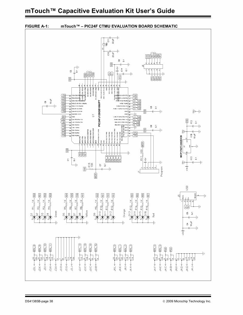
Programmer/Debugger:• Figure A-1: “mTouch™ – PIC24F CTMU Evaluation Board Schematic” –
Microcontroller, Touch Key Plug-in LEDs and Associated Components• Figure A-2: “mTouch™ – PIC18F CTMU Evaluation Board Schematic” –
Microcontroller, Touch Key Plug-in LEDs and Associated Components• Figure A-3: “mTouch™ – CSM Evaluation Board Schematic” –
Microcontroller, Touch Key Plug-in LEDs and Associated Components
© 2009 Microchip Technology Inc. DS41385B-page 37
mTouch™ Capacitive Evaluation Kit User’s Guide
FIGURE A-1: mTouch™ – PIC24F CTMU EVALUATION BOARD SCHEMATIC
22 p
F22
pF
10
F
PIC24FJ128GB106I/PT
MCP1702T-3302E/CB
10
F
10
F
DS41385B-page 38 © 2009 Microchip Technology Inc.

Evaluation Board Schematics
FIGURE A-2: mTouch™ – PIC18F CTMU EVALUATION BOARD SCHEMATIC
R25
J24.7K
VDDVDD
VDD
PGDPGC
RF5RF4
24681012
RC0RC1
RC6RC7
1357911
R244.7K
VBUS R23 56KR26 100K
J3:A 12
J3:D 78
J3:G 1314
J3:J 1920
J3:L BTN_82324
J3:K 2122
J3:I
RD4
1718
J3:H 1516
BTN_9
BTN_10
BTN_11
J4:F BTN_41112
J4:E 910
J4:C 56
J4:B 34
BTN_5
BTN_6
BTN_7
J4:L BTN_024
J4:K 2122
J4:I 1718
J4:H 1516
BTN_1
BTN_2
BTN_3
23
J4:A 2
J4:D 78
J4:G 1314
J4:J 1920
1
J3:F 2
J3:E 7
J3:C 13
J3:B 1920
BTN_12
8
14
R19RD0
VBUS
6
D-D+
12345
C44.7uF
C40.1
J5
VBUS
D-D+ USB
Shield +5V
VBUS
TP1
C13
0.1
MCP1702T–3302E/CB
3 IN OUTQ1
GND1
VDD
TP2
C18
1UF
C12
0.1
2
TP3
D11K
RD5
D2
RD6
D3
RD7
D4
R20RD1
D51K
D6 D7 D8
R21RD2
D91K
D10 D11 D12
R22RD3
D131K
D14 D15 D16
Green
Yellow
Orange
Red
RC7RX/DT1RD4/SPP42RD5/SPP53RD6/SPP64RD7SPP75VSS
6VDD7RB08RB19RB210RB311
N/C 33RC0 32
OSC2 31OSC1 30
VSS 29VDD 28RE2 27RE1 26RE0 25RA5 24
VDDCORE/VCAP 23
PIC18F4XJ50
N/C
12
N/C
13
RB4
14
RB5
15
RB6
16
RB7
17
MCL
R18 19 20 21 22
44 43 42 41 40 39 38 37 36 35 34
RC6
RC5/
D+RC
4/D- NC
RD3/
SPP3
RD2/
SPP2
RD1/
SPP1
RD
0/SP
P0V U
SBRC
2RC
1N/
C
U1
RA1
RA3
RA2
RA0
VDD
C1
0.1
RC7RD4
RD6RD5
RD7
RC0
VDD
BTN_5BTN_4
C96.8uF
C80.1
C1022pf
C1122pf
8 MHzY1
BTN
_3
BTN
_2B
TN_1
BTN
_0
VDD
MCLR
PG
D
PG
C
RB4
RB51
23456
J1
MCLR
Program
R17 100+5V
R1810K
C70.1
D17
Note: The Channels13,14 and 15 are not used, and are grounded in the PIC18F CTMU Evaluation Board.
BTN_7BTN_6
BTN_12
BTN_9
BTN_10
BTN_8
D-D+ RD
3R
D2
RD
0R
D1
VD
D
C30.1
RC6
BTN
_11
RC
1
MBR0520L
© 2009 Microchip Technology Inc. DS41385B-page 39

mTouch™ Capacitive Evaluation Kit User’s Guide
FIGURE A-3: mTouch™ – CSM EVALUATION BOARD SCHEMATIC
PIC
kit™
2
PIC
kit™
Ser
ial
PIC16F727_TQFP
DS41385B-page 40 © 2009 Microchip Technology Inc.

mTouch™ CAPACITIVE EVALUATIONKIT USER’S GUIDE
Appendix B: mTouch™ CSM State Diagrams
FIGURE B-1: mTouch™ – CSM STATE DIAGRAMS
Start – main.c
InitializeSystem()
CalculateButton?
CapSenseStateMachine()
No
Yes
ButtonDecode()
Start – isr()
Service I2C™Interrupt formTouch™ GUI
Check for Timer1overflowOverflow No Overflow
Use previousmeasurement in
CurrentSample & Startnext sample inRestartTimers()
Store measurement inCurrentSample & Start
next sample inRestartTimers()
Return
© 2009 Microchip Technology Inc. DS41385B-page 41

mTouch™ Capacitive Evaluation Kit User’s Guide
InitializeSystem()
No
Yes
Return
No
Yes
Is ReleaseAverage[ButtonIndex]outside of
ReleaseAverageGuardBand?
InitializeSystem()
Is SupplyVoltage outside ofVoltageGuardBand?
Start –CapSenseStateMachine()
Correct, Scaleand Cap
CurrentSample
CalculatePercentReleased
State Machine Design(next page)
DS41385B-page 42 © 2009 Microchip Technology Inc.

mTouch™ CSM State Diagrams
Prime:MeasureSamplePeriodonce for each Button
and store inReleasedAverage
SetSampleTime:MeasureSamplePeriodfor each Button and
average in ReleasedAverage
PrimeNewSample:Store CurrentSample
once for each Button inReleasedAverage
CapSenseStateMachine()
1/2 StartUpDelayis timing
StartUpDelaycomplete
StartUp:Average
CurrentSample inReleasedAverage
1/2 StartUpDelayis timing
StartUpDelay completeDebounce counter< ReleaseCount
Debounce Counter > ReleaseCount
InitializeSystem()
Debounce Counter > PressCount
PercentReleased <OffThreshold
PercentReleased >OffThreshold
PercentReleased >PressThreshold
PercentReleased <PressThreshold
PressedTime< ButtonTimeout
Debounce counter< PressCount
PressedTime> ButtonTimeout
ReleaseDebounce:Start Debounce counter
Released:Average CurrentSample
in ReleasedAverage
PressDebounce:Start Debounce counter
Pressed:Start ButtonTimout
counter
© 2009 Microchip Technology Inc. DS41385B-page 43

mTouch™ Capacitive Evaluation Kit User’s Guide
Start –ButtonDecode()
ButtonState[Button0] >Released
ButtonState[Button1] >Released
ETC...
ButtonState[ButtonF] >Released
Return
Turn LED1 Off Turn LED1 On
Turn LED2 On
Turn LED16 On
Turn LED2 Off
Turn LED16 Off
Yes
Yes
Yes
No
No
No
DS41385B-page 44 © 2009 Microchip Technology Inc.

mTouch™ CAPACITIVE EVALUATIONKIT USER’S GUIDE
Index
BBlock Diagrams
Application Side for the CSM Board ................. 29CAP TOUCH CTMU Evaluation Board............. 33CAP TOUCH CTMU PIC18F Evaluation
Board Application Side ....................... 28CAP TOUCH CTMU PIC24F Evaluation
Board Application Side ....................... 27CSM Evaluation Layout (Top)........................... 32
Board Components .................................................. 31Board H/W ............................................................... 27Board Setup ............................................................. 13
Connecting the H/W.......................................... 13Installing the S/W.............................................. 13Interfacing the Plug-in Boards .......................... 33
CCAP TOUCH CTMU Evaluation Board
Component Layout (Top Side).......................... 30Charge Time Measurement Unit (CTMU) ...........15, 27Components
External Plug-in Components ........................... 322-Channel Slider ........................................ 324-Channel Slider ........................................ 32Direct Key .................................................. 32Matrix Key.................................................. 32
ICSP Programming Header .............................. 31PIC18F46J50 Microcontroller ........................... 31PIC24FJ128GB106 Microcontroller .................. 31Plug-in Interface Connector .............................. 31Plug-in Sensor LEDs ........................................ 31Power Supply.................................................... 31USB mini-B Receptacle .................................... 31
Configuration SettingsReadme ............................................................ 18
CSM State Diagrams ............................................... 41Customer Notification Service.................................... 8Customer Support ...................................................... 9
DDemonstration Application ....................................... 15Direct Key Plug-in .................................................... 16Documentation
Conventions........................................................ 6Layout ................................................................. 5
HHost Computer Requirements.................................. 12
IInitial Board Setup.................................................... 13Internet Address......................................................... 8
KKit Contents.............................................................. 12
MMatrix Key Plug-in .................................................... 17Microchip Internet Web Site ....................................... 8mTouch Sensing Solution
Board Window................................................... 20Diagnostic Tool ................................................. 19Diagnostic Tool Window ................................... 21Global Settings.................................................. 21Individual Sensor Display Setup ....................... 23Introduction ....................................................... 19Sensor Data Charting and Logging................... 24Using the mTouch™ Sensing Solution
Diagnostic Tool................................... 19
OOperational Requirements ....................................... 12
PPIC16F727 Microcontroller ...................................... 29
PIC16F727 Motherboard .................................. 15PIC18F46J50 Microcontroller................................... 28PIC24FJ128GB106 Microcontroller ......................... 27Plug in Power ........................................................... 18Plug in the Sensors .................................................. 18
RReadme
Configuration Settings....................................... 18Recommended Reading ............................................ 7
SSchematics............................................................... 37
CSM Evaluation Board...................................... 40PIC18F CTMU Evaluation Board ...................... 39PIC24F CTMU Evaluation Board ...................... 38
TTouch Interface ........................................................ 15
Sensor Persistence........................................... 16Touch Sensitivity............................................... 15
Touch Sense Demonstrations.................................. 1612-Key Matrix Plug-in Board ............................. 172-Channel Slider Plug-in Board ........................ 174-Channel Slider Plug-in ................................... 178-Key Direct Plug-in Board ............................... 16
Troubleshooting ....................................................... 35
© 2009 Microchip Technology Inc. DS41385B-page 45

Index
UUsing the mTouch™ Sensing Solution
Board Window .................................................. 20Diagnostic Tool ................................................. 19
Using the Diagnostic Tool.......................... 19Diagnostic Tool Window ................................... 21Using the Diagnostic Tool
Global Diagnostic Window Settings........... 21Sensor Data Charting and Logging ........... 24Sensor Display Setup ................................ 23
WWarranty Registration ................................................ 6WWW Address........................................................... 8
© 2009 Microchip Technology Inc. DS41385B-page 46

Index
NOTES:
© 2009 Microchip Technology Inc. DS41385B-page 47

DS41385B-page 48 © 2009 Microchip Technology Inc.
AMERICASCorporate Office2355 West Chandler Blvd.Chandler, AZ 85224-6199Tel: 480-792-7200 Fax: 480-792-7277Technical Support: http://support.microchip.comWeb Address: www.microchip.comAtlantaDuluth, GA Tel: 678-957-9614 Fax: 678-957-1455BostonWestborough, MA Tel: 774-760-0087 Fax: 774-760-0088ChicagoItasca, IL Tel: 630-285-0071 Fax: 630-285-0075ClevelandIndependence, OH Tel: 216-447-0464 Fax: 216-447-0643DallasAddison, TX Tel: 972-818-7423 Fax: 972-818-2924DetroitFarmington Hills, MI Tel: 248-538-2250Fax: 248-538-2260KokomoKokomo, IN Tel: 765-864-8360Fax: 765-864-8387Los AngelesMission Viejo, CA Tel: 949-462-9523 Fax: 949-462-9608Santa ClaraSanta Clara, CA Tel: 408-961-6444Fax: 408-961-6445TorontoMississauga, Ontario, CanadaTel: 905-673-0699 Fax: 905-673-6509
ASIA/PACIFICAsia Pacific OfficeSuites 3707-14, 37th FloorTower 6, The GatewayHarbour City, KowloonHong KongTel: 852-2401-1200Fax: 852-2401-3431Australia - SydneyTel: 61-2-9868-6733Fax: 61-2-9868-6755China - BeijingTel: 86-10-8528-2100 Fax: 86-10-8528-2104China - ChengduTel: 86-28-8665-5511Fax: 86-28-8665-7889China - Hong Kong SARTel: 852-2401-1200 Fax: 852-2401-3431China - NanjingTel: 86-25-8473-2460Fax: 86-25-8473-2470China - QingdaoTel: 86-532-8502-7355Fax: 86-532-8502-7205China - ShanghaiTel: 86-21-5407-5533 Fax: 86-21-5407-5066China - ShenyangTel: 86-24-2334-2829Fax: 86-24-2334-2393China - ShenzhenTel: 86-755-8203-2660 Fax: 86-755-8203-1760China - WuhanTel: 86-27-5980-5300Fax: 86-27-5980-5118China - XiamenTel: 86-592-2388138 Fax: 86-592-2388130China - XianTel: 86-29-8833-7252Fax: 86-29-8833-7256China - ZhuhaiTel: 86-756-3210040 Fax: 86-756-3210049
ASIA/PACIFICIndia - BangaloreTel: 91-80-3090-4444 Fax: 91-80-3090-4080India - New DelhiTel: 91-11-4160-8631Fax: 91-11-4160-8632India - PuneTel: 91-20-2566-1512Fax: 91-20-2566-1513Japan - YokohamaTel: 81-45-471- 6166 Fax: 81-45-471-6122Korea - DaeguTel: 82-53-744-4301Fax: 82-53-744-4302Korea - SeoulTel: 82-2-554-7200Fax: 82-2-558-5932 or 82-2-558-5934Malaysia - Kuala LumpurTel: 60-3-6201-9857Fax: 60-3-6201-9859Malaysia - PenangTel: 60-4-227-8870Fax: 60-4-227-4068Philippines - ManilaTel: 63-2-634-9065Fax: 63-2-634-9069SingaporeTel: 65-6334-8870Fax: 65-6334-8850Taiwan - Hsin ChuTel: 886-3-6578-300Fax: 886-3-6578-370Taiwan - KaohsiungTel: 886-7-536-4818Fax: 886-7-536-4803Taiwan - TaipeiTel: 886-2-2500-6610 Fax: 886-2-2508-0102Thailand - BangkokTel: 66-2-694-1351Fax: 66-2-694-1350
EUROPEAustria - WelsTel: 43-7242-2244-39Fax: 43-7242-2244-393Denmark - CopenhagenTel: 45-4450-2828 Fax: 45-4485-2829France - ParisTel: 33-1-69-53-63-20 Fax: 33-1-69-30-90-79Germany - MunichTel: 49-89-627-144-0 Fax: 49-89-627-144-44Italy - Milan Tel: 39-0331-742611 Fax: 39-0331-466781Netherlands - DrunenTel: 31-416-690399 Fax: 31-416-690340Spain - MadridTel: 34-91-708-08-90Fax: 34-91-708-08-91UK - WokinghamTel: 44-118-921-5869Fax: 44-118-921-5820
Worldwide Sales and Service
03/26/09