mtl surge technologies earthing guide for surge protection€¦ · earthing guide for surge...
TRANSCRIPT
Application NoteTAN 1003
Earthing guidefor surge protection
Synopsis
This publication discusses the major aspects of
earthing surge protection devices (SPDs). The
relationship between SPD earths and the earthing
of associated instrumentation or other equipment
with which the devices are used is also considered.
MTL Surge Technologies
Application Notes from MTL Surge Technologies
MTL Surge Technologies publish an increasing number of Application Notes providing easily understood information on various aspects of lightning andsurge protection. At the date of publication of this Application Note, the list included:–
TAN1001 Lightning surge protection for electronic equipment – a practical guideA relatively brief and easy to understand introduction to the subject – an excellent starting point.
TAN1002 Lightning and surge protection – basic principlesA more detailed account of the mechanism of lightning strikes and the measures needed to achieve an adequate level of protection.
TAN1003 Earthing guide for surge protectionA detailed analysis of the subject of earthing for surge suppression purposes, this is both an easily understood exposition and a valuable reference document.
TAN1004 Surge protection for intrinsically safe systems A description of the best methods of combining surge protection and intrinsically safe systems.
TAN1005 Surge protection for Zone 0 locationsA detailed analysis of this particular aspect of surge suppression in hazardous areas; complements TAN1004.
TAN1006 Surge protection for weighing systemsDiscusses, in some detail, the application of surge suppression to load-cell weighing systems.
TAN1007 Surge protection for Local Area NetworksDiscusses ways in which Local Area Networks can be damaged by lightning induced transients and how they can be protected economically.
TAN1009 Surge protection for electrical power installationsDiscusses aspects of how to protect and install mains devices, with information on earthing and mains systems. A guide tosimple maintenance techniques for surge protection devices is included.
About MTL Surge Technologies
MTL Surge Technologies, the surge protection division of the MTL Instruments Group Plc, designs and manufactures a vast range of protection solutionsfor all your system surge protection requirements. Comprising of two independent but closely linked companies, Telematic and Atlantic ScientificCorporation, MTL Surge Technologies has a combined experience of nearly 50 years within the surge protection industry. MTL Surge Tecnologies suppliesa wide range of Telematic and Atlantic Scientific surge protection devices offering solutions for all AC power, data and signal, telecom, network and wirelessand HF systems.
The MTL Instruments Group has a strong and well respected presence within the Industrial Process market. This, combined with Telematic’s closeassociation with the Water Industry and Atlantic Scientific’s presence in the Networks and Wireless Infrastructure market, means that MTL SurgeTechnologies is well placed to support a wide range of industries around the world.

CONTENTS Page
1 EARTHING FOR SURGE PROTECTION OF ELECTRONIC EQUIPMENT 1.1 Introduction ............................................................................................................................................................................................................................................... 11.2 Practical aspects of surge protection earthing – summary .............................................................................................................................................. 1
2 LIGHTNING – AND THE NEED FOR SURGE PROTECTION .............................................................................................................................................. 22.1 The threat from lightning transients ............................................................................................................................................................................................. 22.2 How lightning interacts with electronic systems...................................................................................................................................................................... 22.3 Lightning surges – how big.................................................................................................................................................................................................................. 32.4 What do we mean by ‘earth’?........................................................................................................................................................................................................... 32.5 Earthing problems – basic questions............................................................................................................................................................................................. 32.6 Complete protection – box it!............................................................................................................................................................................................................. 32.7 An idealised earthing system – next best thing to a metal box......................................................................................................................................... 42.8 A less than ‘ideal’ system..................................................................................................................................................................................................................... 42.9 Recapitulation – the threat from lightning................................................................................................................................................................................... 4
3 SURGES AND SURGE PROTECTION......................................................................................................................................................................................... 53.1 Common and difference mode surges.......................................................................................................................................................................................... 53.2 How surges damage equipment ..................................................................................................................................................................................................... 53.3 Surge protection devices (SPDs) – how they work.................................................................................................................................................................. 53.4 What equipment needs protecting?............................................................................................................................................................................................... 63.5 Case study – telephones, answering machines and modems ........................................................................................................................................... 6
4 EARTHING FOR SURGE PROTECTION IN THE ‘REAL WORLD’....................................................................................................................................... 64.1 Introduction – earth impedance and position............................................................................................................................................................................. 6
5 SURGE EARTH IMPEDANCE ....................................................................................................................................................................................................... 75.1 Inductance and resistance ................................................................................................................................................................................................................. 75.2 A note on ‘skin depth’ ........................................................................................................................................................................................................................... 85.3 Inductance and surges – another angle ...................................................................................................................................................................................... 85.4 Surges on cables – some real measurement ........................................................................................................................................................................... 85.5 Inductance – recapitulation ................................................................................................................................................................................................................ 9
6 SURGE EARTH POSITION ............................................................................................................................................................................................................ 96.1 The trouble with a high impedance surge earth ...................................................................................................................................................................... 96.2 Re-positioning the earth connection to lower the limiting voltage ................................................................................................................................... 96.3 Using a ‘surge link’ when the earth connection cannot be repositioned ..................................................................................................................... 10
7 EARTHING SYSTEM CONFIGURATIONS AND INSTALLATION ..................................................................................................................................... 107.1 Star-point earthing ................................................................................................................................................................................................................................. 107.2 Implementing a star-point earthing system ............................................................................................................................................................................... 117.3 Surge earths and protective earths .............................................................................................................................................................................................. 117.4 Surge protection for external connections ................................................................................................................................................................................ 127.5 Cable layout problems associated with cables entering a building at separate points ......................................................................................... 137.6 Ground electrodes, ground impedance and surges ............................................................................................................................................................... 147.7 Connection to the structural lightning protection system .................................................................................................................................................. 157.8 The other end of the cable ................................................................................................................................................................................................................. 15
8 MISCELLANEOUS TOPICS ........................................................................................................................................................................................................... 168.1 Shielded cables and earth loops ...................................................................................................................................................................................................... 168.2 Protecting baseband transmission systems using co-axial cable .................................................................................................................................... 178.3 Protecting high-frequency co-axial cable systems (e.g. antenna feeds and CCTV) ................................................................................................. 178.4 Protecting the mains supply .............................................................................................................................................................................................................. 188.5 Surge earths and telecommunications functional earths ................................................................................................................................................... 198.6 Integrated earthing for process systems ................................................................................................................................................................................... 198.7 Hazardous areas – earthing for lightning protection ............................................................................................................................................................ 19
9 APPENDICES .................................................................................................................................................................................................................................... 219.A Appendix A – Ground electrode resistance and surge current sharing, a simple model ..................................................................................... 219.B Appendix B – Glossary .......................................................................................................................................................................................................................... 229.C Appendix C – Further reading .......................................................................................................................................................................................................... 22
EARTHING GUIDE FOR SURGE PROTECTION
1 EARTHING FOR SURGE PROTECTION OF ELECTRONIC EQUIPMENT
1.1 Introduction
At MTL Surge Technologies, we believe it is possible to provide economic
and practical surge protection for virtually all electronic systems. However,
the protection provided depends crucially on the quality of the installation –
the best surge protection device is of no use if incorrectly installed.
Installation – and more specifically earthing – is the subject of many
technical queries.
This Application Note is an attempt to share the expertise on earthing and
installation built up over the years to assist you in specifying or installing
systems requiring lightning protection. Much of our experience has been
gained in co-operation with customers, to whom we are grateful, and we
are only too pleased to take note of your views and comments to improve
future editions of this publication.
We have tried to be as clear as possible and to de-mystify a subject
regarded as a ‘black art’ by many. In fact, a good understanding can be
gained using concepts from basic electrical theory only. It is appreciated
that you may well encounter practical difficulties outside the scope of this
publication (in which case, our technical consultancy service may prove of
value) but we also believe that knowledge of the underlying principles is
always helpful for tackling real-life problems.
To make sure the specialist terminology used in surge protection is
understood – a short glossary is included as Appendix B.
1.2 Practical aspects of surge protection earthing – summary
This section briefly summarises what needs to be done
to earth surge protection devices effectively while the
rest of the publication explains why.
1.2.1 Structural protectionMake sure the building housing the equipment is
provided with structural lightning protection in
accordance with national standards (in the UK, these
are established by BS6651).
1.2.2 Cable routeingIf possible, bring all services (i.e. electricity, telephone,
LAN cables, antenna cables, metallic water and gas
pipes) into the building at one point.
1.2.3 Bonding and earthingBond the following services to an earth terminal at one
point (preferably the main distribution board for the
mains electrical supply where applicable) using as short
a bond cable length as possible, to keep them as close as
possible to the same potential:–
Metallic water and gas pipes
Antenna cable
Bond this earth terminal to the building structural
lightning protection as close to the ground as possible.
1.2.4 Surge protectionFit, as close to the earth terminal as possible, appropriate
surge protection devices (SPDs) on ALL incoming cables,
where applicable, for the following services:–
Electricity
Telephone
Local Area Network
Antenna
Video (security) camera
Bond the SPDs to the earth terminal with the shortest
possible length of cable with a minimum cross section of
2.5mm2. Better still, use several cables, spaced apart and
connected electrically in parallel.
Best of all, use sheet metalwork rather than cables.
If you own the entire cable link, fit another SPD at the
remote end.
1.2.5 Diverse cables which cannot be rerouted
Fit appropriate SPDs close to the most strategically
important equipment (e.g. fax machines, modems, etc.)
Bond the SPDs to the equipment earth (e.g. chassis or mains
protective earth) with the shortest possible length of cable
with a minimum cross section of 2.5mm2. Better still, use
several cables, spaced apart and connected electrically in
parallel. Best of all, use sheet metalwork rather than cables.
1
2 LIGHTNING – AND THE NEED FOR SURGE PROTECTION
2.1 The threat from lightning transients
Lightning is a fascinating natural phenomenon – which we can discuss onlybriefly in this publication. However, Appendix C, ‘Further Reading’ lists someexcellent sources of more information.
Briefly, a lightning flash is caused by an electrical current flowing in theatmosphere. Moist air currents interacting with ice particles within acloud lead to the formation of concentrations of electric charges atdifferent heights. Very large voltage differences, of the order of manymillions of volts, develop between the charge concentrations and thebase of the cloud and the surface of the earth. When this voltagedifference becomes sufficient to overcome atmospheric resistance, alightning stroke occurs. Most lightning strokes take place cloud-to-cloudbut some are cloud-to-ground.
In the UK, it is believed that 98% of direct cloud-to-ground strokes carry acurrent of 200kA or less, with a median of around 30kA.
2.2 How lightning interacts with electronic systems
There are a number of ways in which lightning can interact with electronicequipment:–
a) By a direct strike from a cloud-to-ground lightning stroke, sometimesreferred to by the archaic-sounding description of ‘direct attachment’(see 2.2.1)
b) Electric/magnetic coupling, also referred to as capacitive/inductivecoupling, from cloud-to-cloud or cloud-to ground lightning (see 2.2.2).
c) Ground potential surges caused by a cloud-to-ground strike andsometimes referred to as ‘resistive coupling’ (see 2.2.3).
In practice, during a cloud-to-ground strike, various combinations of thesecoupling mechanisms may occur simultaneously.
2.1 Direct attachment
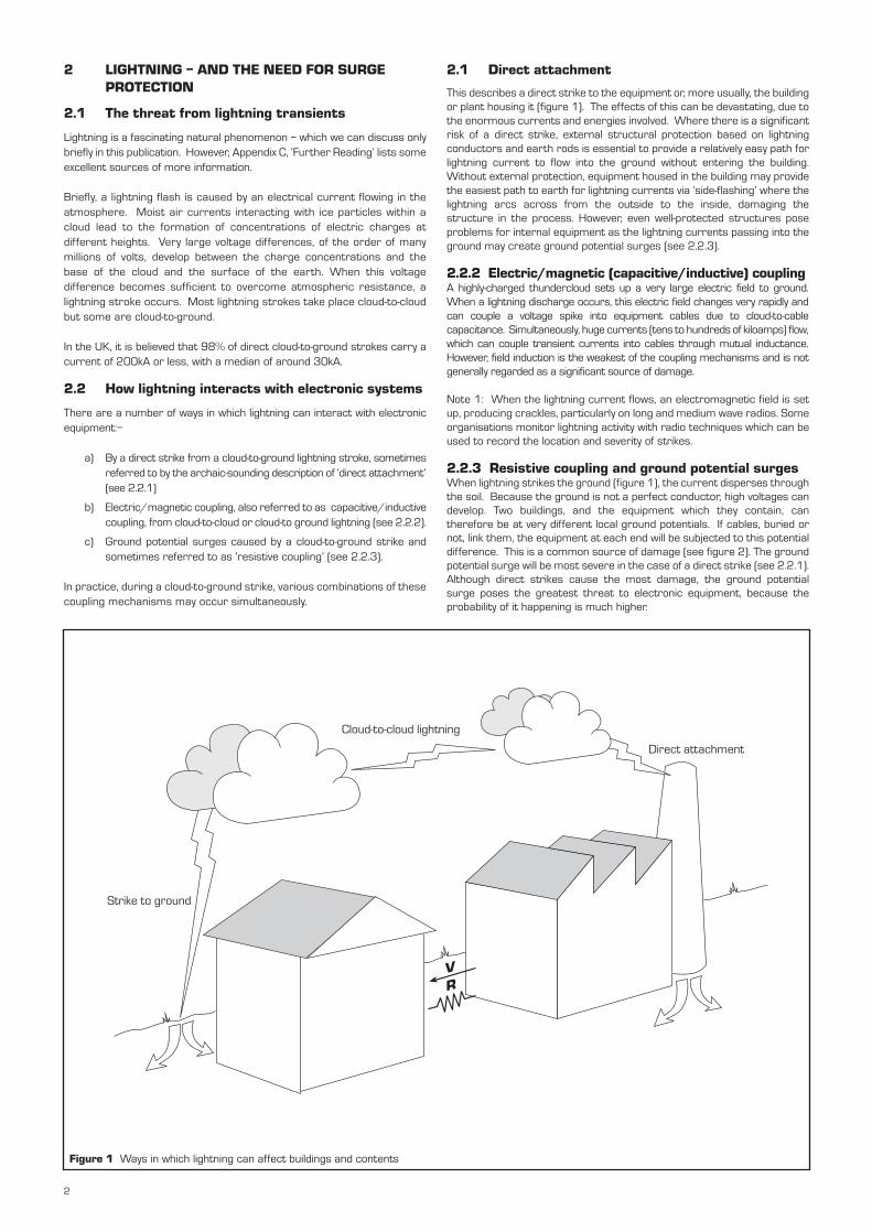
This describes a direct strike to the equipment or, more usually, the buildingor plant housing it (figure 1). The effects of this can be devastating, due tothe enormous currents and energies involved. Where there is a significantrisk of a direct strike, external structural protection based on lightningconductors and earth rods is essential to provide a relatively easy path forlightning current to flow into the ground without entering the building.Without external protection, equipment housed in the building may providethe easiest path to earth for lightning currents via ‘side-flashing’ where thelightning arcs across from the outside to the inside, damaging thestructure in the process. However, even well-protected structures poseproblems for internal equipment as the lightning currents passing into theground may create ground potential surges (see 2.2.3).
2.2.2 Electric/magnetic (capacitive/inductive) coupling A highly-charged thundercloud sets up a very large electric field to ground.When a lightning discharge occurs, this electric field changes very rapidly andcan couple a voltage spike into equipment cables due to cloud-to-cablecapacitance. Simultaneously, huge currents (tens to hundreds of kiloamps) flow,which can couple transient currents into cables through mutual inductance.However, field induction is the weakest of the coupling mechanisms and is notgenerally regarded as a significant source of damage.
Note 1: When the lightning current flows, an electromagnetic field is setup, producing crackles, particularly on long and medium wave radios. Someorganisations monitor lightning activity with radio techniques which can beused to record the location and severity of strikes.
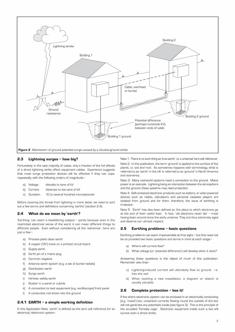
2.2.3 Resistive coupling and ground potential surges When lightning strikes the ground (figure 1), the current disperses throughthe soil. Because the ground is not a perfect conductor, high voltages candevelop. Two buildings, and the equipment which they contain, cantherefore be at very different local ground potentials. If cables, buried ornot, link them, the equipment at each end will be subjected to this potentialdifference. This is a common source of damage (see figure 2). The groundpotential surge will be most severe in the case of a direct strike (see 2.2.1).Although direct strikes cause the most damage, the ground potentialsurge poses the greatest threat to electronic equipment, because theprobability of it happening is much higher.
VR
Cloud-to-cloud lightning
Strike to ground
Direct attachment
Figure 1 Ways in which lightning can affect buildings and contents
2
Lightning stroke
Ground resistance
Building 1 ground
Cable, overhead or buried
Building 1
Building 2
Potential difference (perhaps hundreds KV) between ends of cable
Building 2 ground
2.3 Lightning surges – how big?
Fortunately, in the vast majority of cases, only a fraction of the full effectsof a direct lightning strike affect equipment cables. Experience suggeststhat most surge protection devices will be effective if they can cope,repeatedly, with the following orders of magnitude:–
a) Voltage: kilovolts to tens of kV
b) Current: kiloamps to low tens of kA
c) Duration: 10 to several hundred microseconds
Before covering the threat from lightning in more detail, we need to sortout a few terms and definitions concerning ‘earths’ (section 2.4).
2.4 What do we mean by ‘earth’?
‘Earthing’ can seem a bewildering subject – partly because even in therestricted electrical sense of the word, it can mean different things todifferent people. Even without considering all the ‘extremes’, here arejust a few:–
a) Process plant clean earth
b) A copper (‘0V’) track on a printed circuit board
c) Supply earth
d) Earth pin of a mains plug
e) Common negative
f) Antenna earth system (e.g. a set of buried radials)
g) Distribution earth
h) Surge earth
i) Intrinsic safety earth
j) Busbar in a panel or cubicle
k) A connection to test equipment (e.g. oscilloscope) front panel
l) A conductive rod driven into the ground
2.4.1 EARTH – a simple working definition
In this Application Note, ‘earth’ is defined as the zero volt reference for anelectrical/electronic system.
Note 1: There is no such thing as ‘true earth’, i.e. a universal ‘zero volt reference’.
Note 2: In this publication, the term ‘ground’ is applied to the surface of theplanet, i.e. soil and rock. As sometimes happens with terminology, what isreferred to as ‘earth’ in the UK is referred to as ‘ground’ in North Americaand vice-versa.
Note 3: Many real-world systems need a connection to the ground. Mainspower is an example. Lightning being an interaction between the atmosphereand the ground, these systems may need protection.
Note 4: Self-contained electronic products such as battery- or solar-powereddevices such as radios, calculators and personal cassette players areisolated from ground and for them, therefore, the issue of earthing isirrelevant.
Note 5: ‘Earth’ has also been defined as ‘the place to which electrons goat the end of their useful lives’. In fact, ‘old electrons never die’ – mosthaving been around since the early universe. They are thus extremely agedand deserve our utmost respect.
2.5 Earthing problems – basic questions
Earthing problems can seem impenetrable at first sight – but this need notbe so provided two basic questions are borne in mind at each stage:–
a) Where will current flow?
b) What voltage (or ‘potential difference’) will develop when it does?
Answering these questions is the object of much of this publication.Remember also that:–
c) Lightning-induced current will ultimately flow to ground, i.e.into the soil.
d) When tackling a new installation, a diagram or sketch isusually valuable.
2.6 Complete protection – box it!
If the entire electronic system can be enclosed in an electrically conducting(e.g. ‘metal’) box, unwanted currents flowing round the outside of the boxwill not generate any potentials inside (see figure 3). This is the principle ofthe so-called ‘Faraday cage’. Electronic equipment inside such a box willsurvive even a direct strike.
Figure 2 Mechanism of ground potential surge caused by a cloud-to-ground strike
3
Current
I
I
Metal box
Figure 3 A metal box used as a Faraday cage.
Although at first sight this concept may seem trivial, in aviation it is veryimportant. Aircraft designers strive to make airframes as closely approximateto ‘closed metal boxes’ as possible. In regular service, passenger aircraftexpect to be struck by lightning at least once a year on average. A great deal ofmodelling and testing is undertaken to make sure avionic equipment surviveslightning strikes unscathed.
A word to the wise – this shielding effect of a metal enclosure means it is saferto remain within a metal-bodied car during a thunderstorm than to leave it.
2.7 An idealised earthing system – next best thing to a metal box
When confronted with a real-life lightning protection problem, it is helpful tobear an ‘ideal next best thing to a metal box’ solution in mind, in order toreach the closest practical approximation to this.
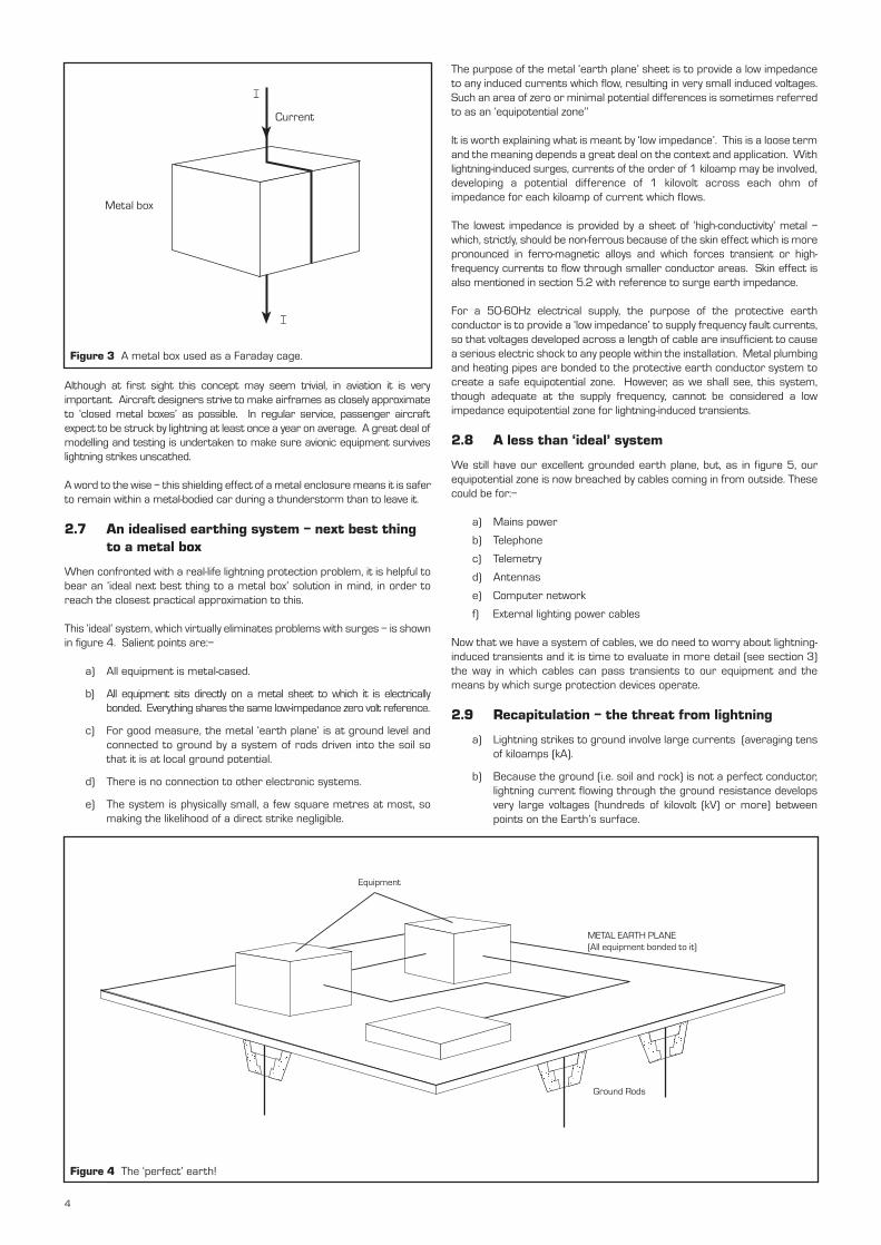
This ‘ideal’ system, which virtually eliminates problems with surges – is shownin figure 4. Salient points are:–
a) All equipment is metal-cased.
b) All equipment sits directly on a metal sheet to which it is electricallybonded. Everything shares the same low-impedance zero volt reference.
c) For good measure, the metal ‘earth plane’ is at ground level andconnected to ground by a system of rods driven into the soil sothat it is at local ground potential.
d) There is no connection to other electronic systems.
e) The system is physically small, a few square metres at most, somaking the likelihood of a direct strike negligible.
Equipment
METAL EARTH PLANE (All equipment bonded to it)
Ground Rods
The purpose of the metal ‘earth plane’ sheet is to provide a low impedanceto any induced currents which flow, resulting in very small induced voltages.Such an area of zero or minimal potential differences is sometimes referredto as an ‘equipotential zone’’
It is worth explaining what is meant by ‘low impedance’. This is a loose termand the meaning depends a great deal on the context and application. Withlightning-induced surges, currents of the order of 1 kiloamp may be involved,developing a potential difference of 1 kilovolt across each ohm ofimpedance for each kiloamp of current which flows.
The lowest impedance is provided by a sheet of ‘high-conductivity’ metal –which, strictly, should be non-ferrous because of the skin effect which is morepronounced in ferro-magnetic alloys and which forces transient or high-frequency currents to flow through smaller conductor areas. Skin effect isalso mentioned in section 5.2 with reference to surge earth impedance.
For a 50-60Hz electrical supply, the purpose of the protective earthconductor is to provide a ‘low impedance’ to supply frequency fault currents,so that voltages developed across a length of cable are insufficient to causea serious electric shock to any people within the installation. Metal plumbingand heating pipes are bonded to the protective earth conductor system tocreate a safe equipotential zone. However, as we shall see, this system,though adequate at the supply frequency, cannot be considered a lowimpedance equipotential zone for lightning-induced transients.
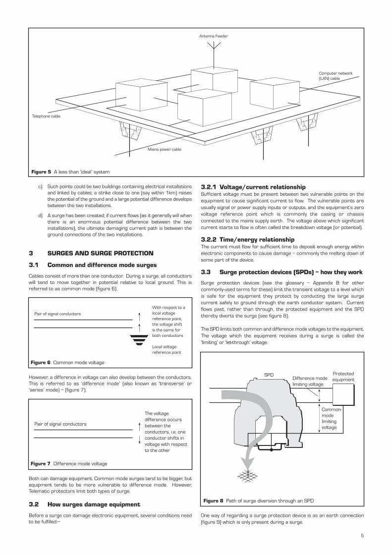
2.8 A less than ‘ideal’ system
We still have our excellent grounded earth plane, but, as in figure 5, ourequipotential zone is now breached by cables coming in from outside. Thesecould be for:–
a) Mains power
b) Telephone
c) Telemetry
d) Antennas
e) Computer network
f) External lighting power cables
Now that we have a system of cables, we do need to worry about lightning-induced transients and it is time to evaluate in more detail (see section 3)the way in which cables can pass transients to our equipment and themeans by which surge protection devices operate.
2.9 Recapitulation – the threat from lightning
a) Lightning strikes to ground involve large currents (averaging tensof kiloamps (kA).
b) Because the ground (i.e. soil and rock) is not a perfect conductor,lightning current flowing through the ground resistance developsvery large voltages (hundreds of kilovolt (kV) or more) betweenpoints on the Earth’s surface.
Figure 4 The ‘perfect’ earth!
4
Antenna Feeder
Telephone cable
Mains power cable
Computer network (LAN) cable
Figure 5 A less than ‘ideal’ system
c) Such points could be two buildings containing electrical installationsand linked by cables; a strike close to one (say within 1km) raisesthe potential of the ground and a large potential difference developsbetween the two installations.
d) A surge has been created; if current flows (as it generally will whenthere is an enormous potential difference between the twoinstallations), the ultimate damaging current path is between theground connections of the two installations.
3 SURGES AND SURGE PROTECTION
3.1 Common and difference mode surges
Cables consist of more than one conductor. During a surge, all conductorswill tend to move together in potential relative to local ground. This isreferred to as common mode (figure 6).
However, a difference in voltage can also develop between the conductors.This is referred to as ‘difference mode’ (also known as ‘transverse’ or‘series’ mode) – (figure 7).
Both can damage equipment. Common mode surges tend to be bigger, butequipment tends to be more vulnerable to difference mode. However,Telematic protectors limit both types of surge.
3.2 How surges damage equipment
Before a surge can damage electronic equipment, several conditions needto be fulfilled:–
With respect to a local voltage reference point, the voltage shift is the same for both conductors Local voltage reference point
Pair of signal conductors
The voltage difference occurs between the conductors, i.e. one conductor shifts in voltage with respect to the other
Pair of signal conductors
Figure 6 Common mode voltage
Figure 7 Difference mode voltage
3.2.1 Voltage/current relationshipSufficient voltage must be present between two vulnerable points on theequipment to cause significant current to flow. The vulnerable points areusually signal or power supply inputs or outputs, and the equipment’s zerovoltage reference point which is commonly the casing or chassisconnected to the mains supply earth. The voltage above which significantcurrent starts to flow is often called the breakdown voltage (or potential).
3.2.2 Time/energy relationshipThe current must flow for sufficient time to deposit enough energy withinelectronic components to cause damage – commonly the melting down ofsome part of the device.
3.3 Surge protection devices (SPDs) – how they work
Surge protection devices (see the glossary – Appendix B for othercommonly-used terms for these) limit the transient voltage to a level whichis safe for the equipment they protect by conducting the large surgecurrent safely to ground through the earth conductor system. Currentflows past, rather than through, the protected equipment and the SPDthereby diverts the surge (see figure 8).
The SPD limits both common and difference mode voltages to the equipment.The voltage which the equipment receives during a surge is called the‘limiting’ or ‘let-through’ voltage.
One way of regarding a surge protection device is as an earth connection(figure 9) which is only present during a surge.
SPDDifference mode limiting voltage
Protected equipment
Common- mode limiting voltage
Figure 8 Path of surge diversion through an SPD
5
Surge protection device (SPD)
Cable To equipment
Normal
Surge
Figure 9 SPD acting as an earth connection
3.4 What equipment needs protecting?
In principle, wherever a cable enters an equipotential zone, equipment connectedto that cable is exposed to possibly damaging surges. The degree of risk dependson factors such as:–
a) Cable length.
b) Frequency of occurrence of lightning.
c) Exposure of the site to lightning and the degree of isolation.
d) Whether cables run above ground or underground.It is essential to protect ALL cables which introduce a significantrisk, as will be seen later.
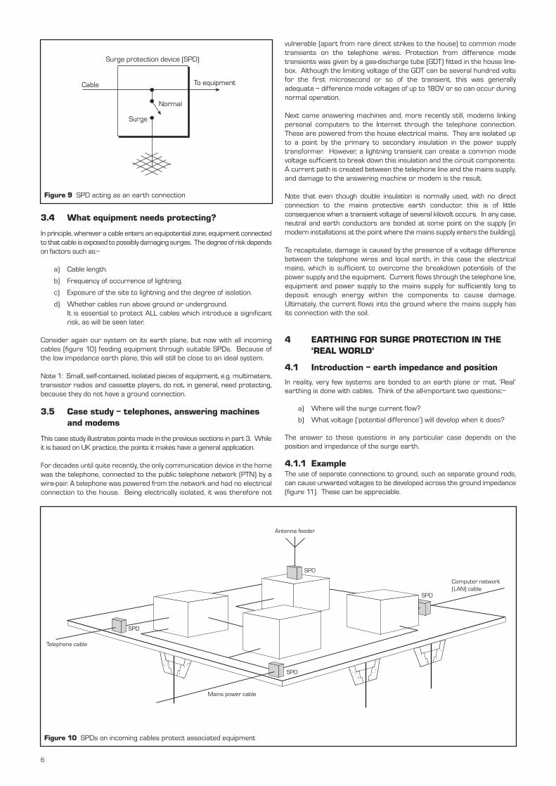
Consider again our system on its earth plane, but now with all incomingcables (figure 10) feeding equipment through suitable SPDs. Because ofthe low impedance earth plane, this will still be close to an ideal system.
Note 1: Small, self-contained, isolated pieces of equipment, e.g. multimeters,transistor radios and cassette players, do not, in general, need protecting,because they do not have a ground connection.
3.5 Case study – telephones, answering machines and modems
This case study illustrates points made in the previous sections in part 3. Whileit is based on UK practice, the points it makes have a general application.
For decades until quite recently, the only communication device in the homewas the telephone, connected to the public telephone network (PTN) by awire-pair. A telephone was powered from the network and had no electricalconnection to the house. Being electrically isolated, it was therefore not
Antenna feeder
SPD
SPD
SPD
SPD
Computer network (LAN) cable
Mains power cable
Telephone cable
Figure 10 SPDs on incoming cables protect associated equipment
vulnerable (apart from rare direct strikes to the house) to common modetransients on the telephone wires. Protection from difference modetransients was given by a gas-discharge tube (GDT) fitted in the house line-box. Although the limiting voltage of the GDT can be several hundred voltsfor the first microsecond or so of the transient, this was generallyadequate – difference mode voltages of up to 180V or so can occur duringnormal operation.
Next came answering machines and, more recently still, modems linkingpersonal computers to the Internet through the telephone connection.These are powered from the house electrical mains. They are isolated upto a point by the primary to secondary insulation in the power supplytransformer. However, a lightning transient can create a common modevoltage sufficient to break down this insulation and the circuit components.A current path is created between the telephone line and the mains supply,and damage to the answering machine or modem is the result.
Note that even though double insulation is normally used, with no directconnection to the mains protective earth conductor, this is of littleconsequence when a transient voltage of several kilovolt occurs. In any case,neutral and earth conductors are bonded at some point on the supply (inmodern installations at the point where the mains supply enters the building).
To recapitulate, damage is caused by the presence of a voltage differencebetween the telephone wires and local earth, in this case the electricalmains, which is sufficient to overcome the breakdown potentials of thepower supply and the equipment. Current flows through the telephone line,equipment and power supply to the mains supply for sufficiently long todeposit enough energy within the components to cause damage.Ultimately, the current flows into the ground where the mains supply hasits connection with the soil.
4 EARTHING FOR SURGE PROTECTION IN THE ‘REAL WORLD’
4.1 Introduction – earth impedance and position
In reality, very few systems are bonded to an earth plane or mat. ‘Real’earthing is done with cables. Think of the all-important two questions:–
a) Where will the surge current flow?
b) What voltage (‘potential difference’) will develop when it does?
The answer to these questions in any particular case depends on theposition and impedance of the surge earth.
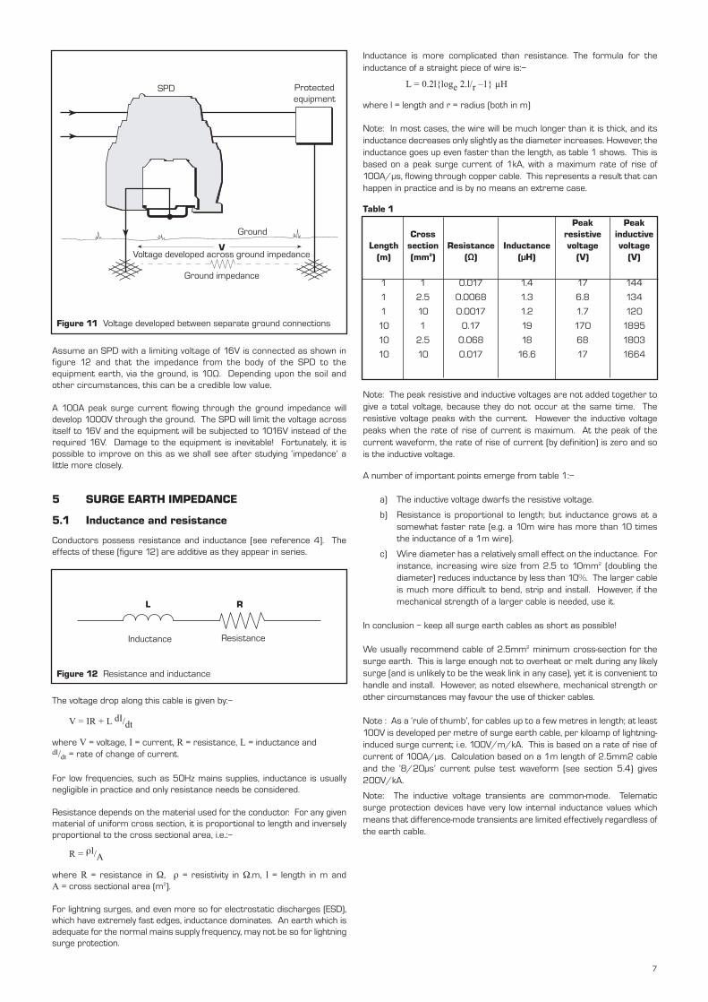
4.1.1 ExampleThe use of separate connections to ground, such as separate ground rods,can cause unwanted voltages to be developed across the ground impedance(figure 11). These can be appreciable.
6
Inductance is more complicated than resistance. The formula for theinductance of a straight piece of wire is:–
L = 0.2lloge 2.l/r Ð1 µH
where l = length and r = radius (both in m)
Note: In most cases, the wire will be much longer than it is thick, and itsinductance decreases only slightly as the diameter increases. However, theinductance goes up even faster than the length, as table 1 shows. This isbased on a peak surge current of 1kA, with a maximum rate of rise of100A/µs, flowing through copper cable. This represents a result that canhappen in practice and is by no means an extreme case.
Table 1
Note: The peak resistive and inductive voltages are not added together togive a total voltage, because they do not occur at the same time. Theresistive voltage peaks with the current. However the inductive voltagepeaks when the rate of rise of current is maximum. At the peak of thecurrent waveform, the rate of rise of current (by definition) is zero and sois the inductive voltage.
A number of important points emerge from table 1:–
a) The inductive voltage dwarfs the resistive voltage.
b) Resistance is proportional to length; but inductance grows at asomewhat faster rate (e.g. a 10m wire has more than 10 timesthe inductance of a 1m wire).
c) Wire diameter has a relatively small effect on the inductance. Forinstance, increasing wire size from 2.5 to 10mm2 (doubling thediameter) reduces inductance by less than 10%. The larger cableis much more difficult to bend, strip and install. However, if themechanical strength of a larger cable is needed, use it.
In conclusion – keep all surge earth cables as short as possible!
We usually recommend cable of 2.5mm2 minimum cross-section for thesurge earth. This is large enough not to overheat or melt during any likelysurge (and is unlikely to be the weak link in any case), yet it is convenient tohandle and install. However, as noted elsewhere, mechanical strength orother circumstances may favour the use of thicker cables.
Note : As a ‘rule of thumb’, for cables up to a few metres in length; at least100V is developed per metre of surge earth cable, per kiloamp of lightning-induced surge current; i.e. 100V/m/kA. This is based on a rate of rise ofcurrent of 100A/µs. Calculation based on a 1m length of 2.5mm2 cableand the ‘8/20µs’ current pulse test waveform (see section 5.4) gives200V/kA.
Note: The inductive voltage transients are common-mode. Telematicsurge protection devices have very low internal inductance values whichmeans that difference-mode transients are limited effectively regardless ofthe earth cable.
Assume an SPD with a limiting voltage of 16V is connected as shown infigure 12 and that the impedance from the body of the SPD to theequipment earth, via the ground, is 10Ω. Depending upon the soil andother circumstances, this can be a credible low value.
A 100A peak surge current flowing through the ground impedance willdevelop 1000V through the ground. The SPD will limit the voltage acrossitself to 16V and the equipment will be subjected to 1016V instead of therequired 16V. Damage to the equipment is inevitable! Fortunately, it ispossible to improve on this as we shall see after studying ‘impedance’ alittle more closely.
5 SURGE EARTH IMPEDANCE
5.1 Inductance and resistance
Conductors possess resistance and inductance [see reference 4]. Theeffects of these (figure 12) are additive as they appear in series.
The voltage drop along this cable is given by:–
V = IR + L dI/dt
where V = voltage, I = current, R = resistance, L = inductance anddI/dt = rate of change of current.
For low frequencies, such as 50Hz mains supplies, inductance is usuallynegligible in practice and only resistance needs be considered.
Resistance depends on the material used for the conductor. For any givenmaterial of uniform cross section, it is proportional to length and inverselyproportional to the cross sectional area, i.e.:–
R = rl/A
where R = resistance in W, r = resistivity in W.m, l = length in m andA = cross sectional area (m2).
For lightning surges, and even more so for electrostatic discharges (ESD),which have extremely fast edges, inductance dominates. An earth which isadequate for the normal mains supply frequency, may not be so for lightningsurge protection.
RL
Inductance Resistance
V
SPD Protected equipment
Ground
Voltage developed across ground impedance
Ground impedance
Figure 11 Voltage developed between separate ground connections
Figure 12 Resistance and inductance
Peak PeakCross resistive inductive
Length section Resistance Inductance voltage voltage(m) (mm2) (Ω) (µH) (V) (V)
1 1 0.017 1.4 17 144
1 2.5 0.0068 1.3 6.8 134
1 10 0.0017 1.2 1.7 120
10 1 0.17 19 170 1895
10 2.5 0.068 18 68 1803
10 10 0.017 16.6 17 1664
7
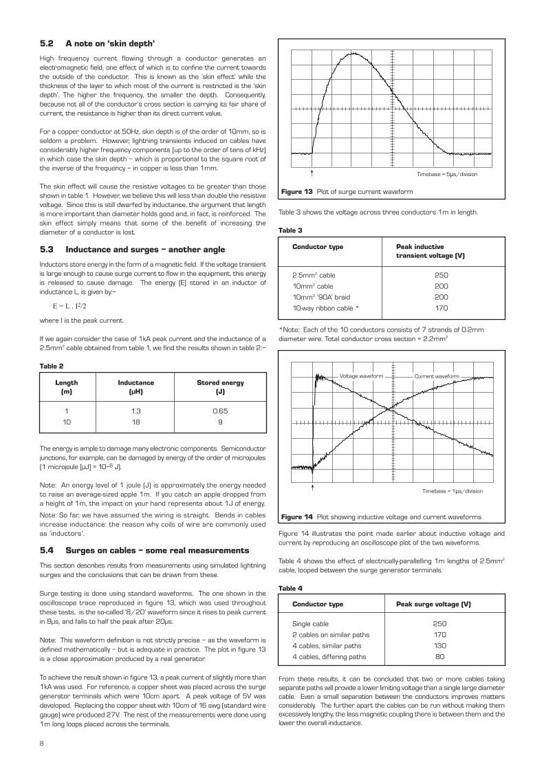
Table 3 shows the voltage across three conductors 1m in length.
Table 3
*Note: Each of the 10 conductors consists of 7 strands of 0.2mmdiameter wire. Total conductor cross section = 2.2mm2
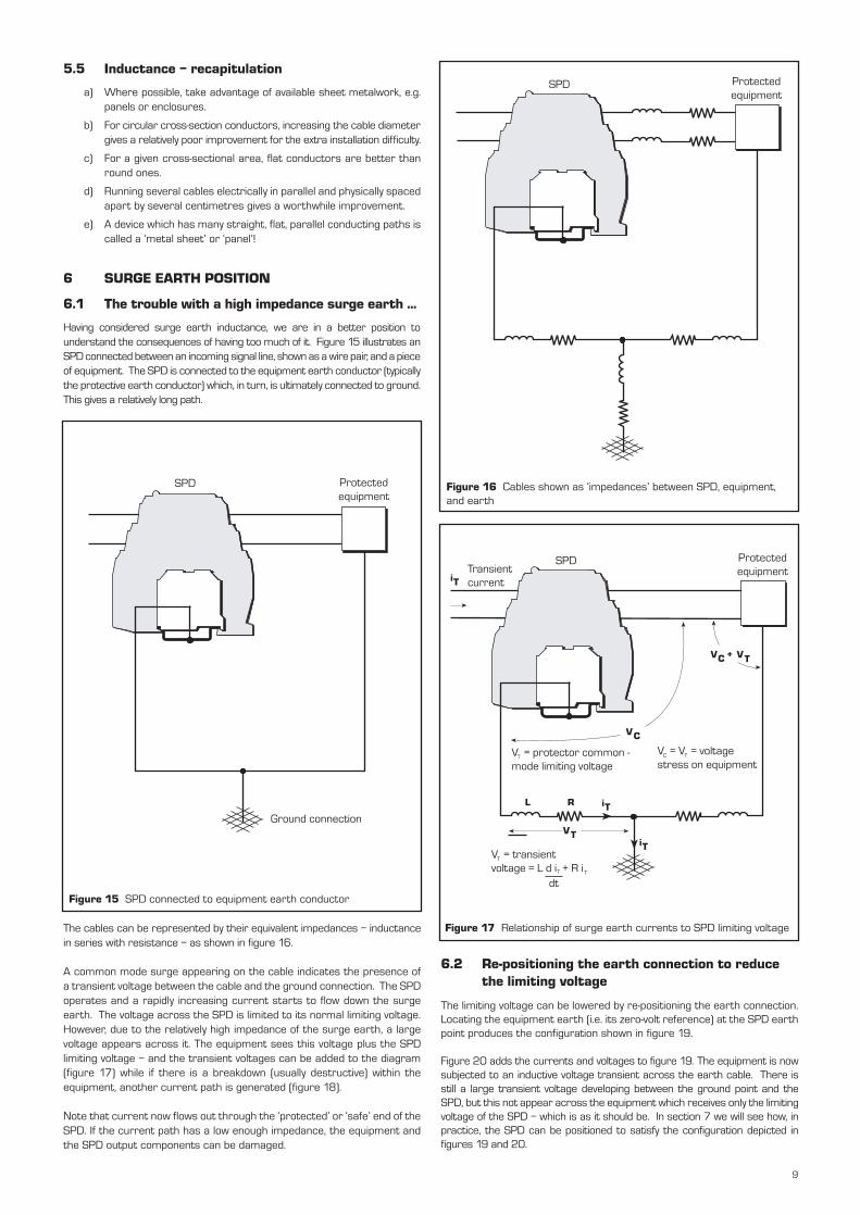
Figure 14 illustrates the point made earlier about inductive voltage andcurrent by reproducing an oscilloscope plot of the two waveforms.
Table 4 shows the effect of electrically-parallelling 1m lengths of 2.5mm2
cable, looped between the surge generator terminals.
Table 4
From these results, it can be concluded that two or more cables takingseparate paths will provide a lower limiting voltage than a single large diametercable. Even a small separation between the conductors improves mattersconsiderably. The further apart the cables can be run without making themexcessively lengthy, the less magnetic coupling there is between them and thelower the overall inductance.
Conductor type Peak surge voltage (V)
Single cable 250
2 cables on similar paths 170
4 cables, similar paths 130
4 cables, differing paths 80
5.2 A note on ‘skin depth’
High frequency current flowing through a conductor generates anelectromagnetic field, one effect of which is to confine the current towardsthe outside of the conductor. This is known as the ‘skin effect’ while thethickness of the layer to which most of the current is restricted is the ‘skindepth’. The higher the frequency, the smaller the depth. Consequently,because not all of the conductor’s cross section is carrying its fair share ofcurrent, the resistance is higher than its direct current value.
For a copper conductor at 50Hz, skin depth is of the order of 10mm, so isseldom a problem. However, lightning transients induced on cables haveconsiderably higher frequency components (up to the order of tens of kHz)in which case the skin depth – which is proportional to the square root ofthe inverse of the frequency – in copper is less than 1mm.
The skin effect will cause the resistive voltages to be greater than thoseshown in table 1. However, we believe this will less than double the resistivevoltage. Since this is still dwarfed by inductance, the argument that lengthis more important than diameter holds good and, in fact, is reinforced. Theskin effect simply means that some of the benefit of increasing thediameter of a conductor is lost.
5.3 Inductance and surges – another angle
Inductors store energy in the form of a magnetic field. If the voltage transientis large enough to cause surge current to flow in the equipment, this energyis released to cause damage. The energy (E) stored in an inductor ofinductance L, is given by:–
E = L . I2/2
where I is the peak current.
If we again consider the case of 1kA peak current and the inductance of a2.5mm2 cable obtained from table 1, we find the results shown in table 2:–
Table 2
The energy is ample to damage many electronic components. Semiconductorjunctions, for example, can be damaged by energy of the order of microjoules(1 microjoule [µJ] = 10–6 J).
Note: An energy level of 1 joule (J) is approximately the energy neededto raise an average-sized apple 1m. If you catch an apple dropped froma height of 1m, the impact on your hand represents about 1J of energy.
Note: So far, we have assumed the wiring is straight. Bends in cablesincrease inductance: the reason why coils of wire are commonly usedas ‘inductors’.
5.4 Surges on cables – some real measurements
This section describes results from measurements using simulated lightningsurges and the conclusions that can be drawn from these.
Surge testing is done using standard waveforms. The one shown in theoscilloscope trace reproduced in figure 13, which was used throughoutthese tests, is the so-called ‘8/20’ waveform since it rises to peak currentin 8µs, and falls to half the peak after 20µs.
Note: This waveform definition is not strictly precise – as the waveform isdefined mathematically – but is adequate in practice. The plot in figure 13is a close approximation produced by a real generator.
To achieve the result shown in figure 13, a peak current of slightly more than1kA was used. For reference, a copper sheet was placed across the surgegenerator terminals which were 10cm apart. A peak voltage of 5V wasdeveloped. Replacing the copper sheet with 10cm of 16 swg (standard wiregauge) wire produced 27V. The rest of the measurements were done using1m long loops placed across the terminals.
Voltage waveform Current waveform
Timebase = 1µs/division
Figure 14 Plot showing inductive voltage and current waveforms
Length Inductance Stored energy(m) (µH) (J)
1 1.3 0.65
10 18 9
Conductor type Peak inductivetransient voltage (V)
2.5mm2 cable 250
10mm2 cable 200
10mm2 ‘90A’ braid 200
10-way ribbon cable * 170
8
Timebase = 5µs/division
Figure 13 Plot of surge current waveform
5.5 Inductance – recapitulation
a) Where possible, take advantage of available sheet metalwork, e.g.panels or enclosures.
b) For circular cross-section conductors, increasing the cable diametergives a relatively poor improvement for the extra installation difficulty.
c) For a given cross-sectional area, flat conductors are better thanround ones.
d) Running several cables electrically in parallel and physically spacedapart by several centimetres gives a worthwhile improvement.
e) A device which has many straight, flat, parallel conducting paths iscalled a ‘metal sheet’ or ‘panel’!
6 SURGE EARTH POSITION
6.1 The trouble with a high impedance surge earth ...
Having considered surge earth inductance, we are in a better position tounderstand the consequences of having too much of it. Figure 15 illustrates anSPD connected between an incoming signal line, shown as a wire pair, and a pieceof equipment. The SPD is connected to the equipment earth conductor (typicallythe protective earth conductor) which, in turn, is ultimately connected to ground.This gives a relatively long path.
The cables can be represented by their equivalent impedances – inductancein series with resistance – as shown in figure 16.
A common mode surge appearing on the cable indicates the presence ofa transient voltage between the cable and the ground connection. The SPDoperates and a rapidly increasing current starts to flow down the surgeearth. The voltage across the SPD is limited to its normal limiting voltage.However, due to the relatively high impedance of the surge earth, a largevoltage appears across it. The equipment sees this voltage plus the SPDlimiting voltage – and the transient voltages can be added to the diagram(figure 17) while if there is a breakdown (usually destructive) within theequipment, another current path is generated (figure 18).
Note that current now flows out through the ‘protected’ or ‘safe’ end of theSPD. If the current path has a low enough impedance, the equipment andthe SPD output components can be damaged.
SPD Protected equipment
Ground connection
Figure 15 SPD connected to equipment earth conductor
Protected equipment
SPD
Figure 16 Cables shown as ‘impedances’ between SPD, equipment,and earth
VT
iT
iT
iT
VC + VT
VC
L R
Transient current
SPD Protected equipment
V = protector common - mode limiting voltage
TV = V = voltage stress on equipment
C T
V = transient voltage = L d i + R i
T
T
dtT
Figure 17 Relationship of surge earth currents to SPD limiting voltage
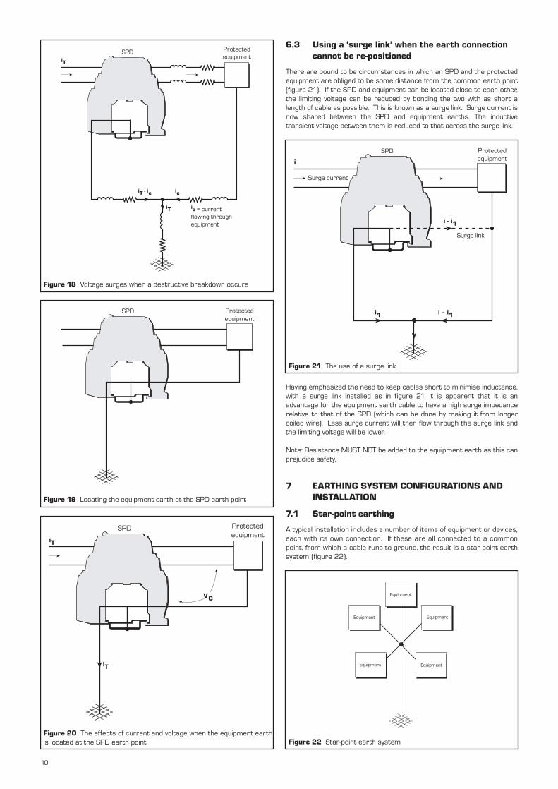
6.2 Re-positioning the earth connection to reduce the limiting voltage
The limiting voltage can be lowered by re-positioning the earth connection.Locating the equipment earth (i.e. its zero-volt reference) at the SPD earthpoint produces the configuration shown in figure 19.
Figure 20 adds the currents and voltages to figure 19. The equipment is nowsubjected to an inductive voltage transient across the earth cable. There isstill a large transient voltage developing between the ground point and theSPD, but this not appear across the equipment which receives only the limitingvoltage of the SPD – which is as it should be. In section 7 we will see how, inpractice, the SPD can be positioned to satisfy the configuration depicted infigures 19 and 20.
9
iT
iT - ie ie
iT
SPD Protected equipment
ie = current flowing through equipment
Figure 18 Voltage surges when a destructive breakdown occurs
SPD Protected equipment
Figure 19 Locating the equipment earth at the SPD earth point
iT
iT
VC
SPD Protected equipment
Figure 20 The effects of current and voltage when the equipment earthis located at the SPD earth point
6.3 Using a ‘surge link’ when the earth connection cannot be re-positioned
There are bound to be circumstances in which an SPD and the protectedequipment are obliged to be some distance from the common earth point(figure 21). If the SPD and equipment can be located close to each other,the limiting voltage can be reduced by bonding the two with as short alength of cable as possible. This is known as a surge link. Surge current isnow shared between the SPD and equipment earths. The inductivetransient voltage between them is reduced to that across the surge link.
Having emphasized the need to keep cables short to minimise inductance,with a surge link installed as in figure 21, it is apparent that it is anadvantage for the equipment earth cable to have a high surge impedancerelative to that of the SPD (which can be done by making it from longercoiled wire). Less surge current will then flow through the surge link andthe limiting voltage will be lower.
Note: Resistance MUST NOT be added to the equipment earth as this canprejudice safety.
7 EARTHING SYSTEM CONFIGURATIONS AND INSTALLATION
7.1 Star-point earthing
A typical installation includes a number of items of equipment or devices,each with its own connection. If these are all connected to a commonpoint, from which a cable runs to ground, the result is a star-point earthsystem (figure 22).
i - i1i1
i
i - i1
Surge current
Protected equipment
Surge link
SPD
Figure 21 The use of a surge link
Equipment
Equipment Equipment
Equipment Equipment
Figure 22 Star-point earth system
10
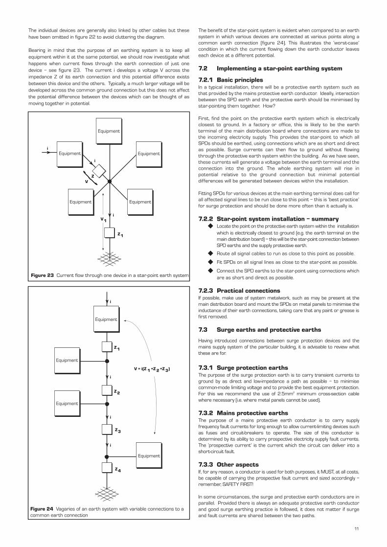
The individual devices are generally also linked by other cables but thesehave been omitted in figure 22 to avoid cluttering the diagram.
Bearing in mind that the purpose of an earthing system is to keep allequipment within it at the same potential, we should now investigate whathappens when current flows through the earth connection of just onedevice – see figure 23. The current i develops a voltage V across theimpedance Z of its earth connection and this potential difference existsbetween this device and the others. Typically, a much larger voltage will bedeveloped across the common ground connection but this does not affectthe potential difference between the devices which can be thought of asmoving together in potential.
i
ZV
i
iV1
Z1
Equipment
Equipment
Equipment
EquipmentEquipment
Figure 23 Current flow through one device in a star-point earth system
i
Z4
Z1
Z2
i
i
Z3
i
V = i(Z 1 +Z 2 +Z 3)
Equipment
Equipment
Equipment
Equipment
Figure 24 Vagaries of an earth system with variable connections to acommon earth connection
The benefit of the star-point system is evident when compared to an earthsystem in which various devices are connected at various points along acommon earth connection (figure 24). This illustrates the ‘worst-case’condition in which the current flowing down the earth conductor leaveseach device at a different potential.
7.2 Implementing a star-point earthing system
7.2.1 Basic principlesIn a typical installation, there will be a protective earth system such asthat provided by the mains protective earth conductor. Ideally, interactionbetween the SPD earth and the protective earth should be minimised bystar-pointing them together. How?
First, find the point on the protective earth system which is electricallyclosest to ground. In a factory or office, this is likely to be the earthterminal of the main distribution board where connections are made tothe incoming electricity supply. This provides the star-point to which allSPDs should be earthed, using connections which are as short and directas possible. Surge currents can then flow to ground without flowingthrough the protective earth system within the building. As we have seen,these currents will generate a voltage between the earth terminal and theconnection into the ground. The whole earthing system will rise inpotential relative to the ground connection but minimal potentialdifferences will be generated between devices within the installation.
Fitting SPDs for various devices at the main earthing terminal does call forall affected signal lines to be run close to this point – this is ‘best practice’for surge protection and should be done more often than it actually is.
7.2.2 Star-point system installation – summary Locate the point on the protective earth system within the installation
which is electrically closest to ground (e.g. the earth terminal on themain distribution board) – this will be the star-point connection betweenSPD earths and the supply protective earth.
Route all signal cables to run as close to this point as possible.
Fit SPDs on all signal lines as close to the star-point as possible.
Connect the SPD earths to the star-point using connections whichare as short and direct as possible.
7.2.3 Practical connectionsIf possible, make use of system metalwork, such as may be present at themain distribution board and mount the SPDs on metal panels to minimise theinductance of their earth connections, taking care that any paint or grease isfirst removed.
7.3 Surge earths and protective earths
Having introduced connections between surge protection devices and themains supply system of the particular building, it is advisable to review whatthese are for.
7.3.1 Surge protection earthsThe purpose of the surge protection earth is to carry transient currents toground by as direct and low-impedance a path as possible – to minimisecommon-mode limiting voltage and to provide the best equipment protection.For this we recommend the use of 2.5mm2 minimum cross-section cablewhere necessary (i.e. where metal panels cannot be used).
7.3.2 Mains protective earthsThe purpose of a mains protective earth conductor is to carry supplyfrequency fault currents for long enough to allow current-limiting devices suchas fuses and circuit-breakers to operate. The size of this conductor isdetermined by its ability to carry prospective electricity supply fault currents.The ‘prospective current’ is the current which the circuit can deliver into ashort-circuit fault.
7.3.3 Other aspectsIf, for any reason, a conductor is used for both purposes, it MUST, at all costs,be capable of carrying the prospective fault current and sized accordingly –remember, SAFETY FIRST!
In some circumstances, the surge and protective earth conductors are inparallel. Provided there is always an adequate protective earth conductorand good surge earthing practice is followed, it does not matter if surgeand fault currents are shared between the two paths.
11

To make sure the correct size and type of mains protective earth conductorsare used, consult the appropriate regulations. In the UK, this is the IEE WiringRegulations (BS7671:1992: IEE Wiring Regulations, 16th edition).
7.4 Surge protection for external connections
Manufacturers of surge protection devices (including Telematic) recommendfitting SPDs to each cable which enters an installation from outside thebuilding – why? Is this simply a ploy to sell more products?
The answer is NO, for two reasons:–
a) Each cable provides an opportunity for surges to enter the building.
b) Failure to protect all cables may allow a surge on one to coupleto another.
7.4.1 Surges entering a buildingTo illustrate the first point a), consider a device with two cables, both ofwhich come from points remote from the installation and only one of whichis fitted with an SPD (figure 25). If, during a thunderstorm, there is alightning strike to ground near the remote end of the unprotected cable, thedevice will suffer from a surge on the unprotected line. Breakdown(probably destructive) occurs and current flows to ground, either throughthe device or through its ‘protected’ port and the output side of the SPD. Inthe latter case, both the device and the SPD may be damaged (figure 26).
Equipment
Signal line 1
Signal line 2
SPD
Figure 25 Equipment with one unprotected signal line
Surge current
EquipmentSPD
Figure 26 Breakdown paths caused by a surge on an unprotected signal line
7.4.2 Surges coupling from one cable to anotherFor surge coupling, consider the simple system shown by figure 27 whichdepicts a signal cable and an item of mains-powered equipment.
During a surge, the SPD on the signal line operates correctly and transientcurrent flows to ground through the earth conductor. However, theinductive voltage across the earth conductor appears between the othermains supply conductors (figure 28). The neutral-earth voltage depends onthe distance to the bond between them. If the SPD is at the main earthterminal of the distribution board, where the neutral-earth bond is situated,there will be little or no neutral earth transient and the inductive voltage willappear between the ‘live’ and the other two conductors. An SPD on themains supply (figure 29) will limit this surge to a safe level.
SPD Equipment
Signal line
Neutral earth bond
E
N
L
Power supply
Figure 27 Configuration in which surge coupling can occur
Surge currenti
SPD Equipment
Power supply
Signal line
Neural earth bond
E
N
L
Inductive transient
i
Figure 28 The effect of surge coupling
12

Figure 31 illustrates an optimum installation in a slightly more practicalconfiguration.
7.5 Cable layout problems associated with cables entering a building at separate points
In practice, signal cables frequently enter buildings at points remote fromthe main distribution board earth terminal which is the earth referencepoint for earthed equipment in the building. What then? SPDs are fittedon both the signal line and the mains supply (as described in section 7.4) toprovide protection to the equipment served by the cable. However, there is
i
SPD Equipment
Power supply
Signal line
Neural earth bond
E
N
L
Inductive transient
Mains SPD
i
Figure 29 Preventing surge coupling having adverse effects
Outside building
Inside building
Mains distribution boardSPD
To protected equipment
To protected equipment
Mains SPD
Mains earth terminal
Building ground
NB: Mount SPDs on earthed metalwork, if possible, for minimal earth impedance
L
N
L
N
E
Figure 30 Optimum installation
a very long cable path back to the earth terminal. How can we mitigate theeffects of this? There are several possibilities:–
a) Equipment relatively isolated: no signal cable links to other equipmentin the building; earth cable not shared with other equipment – seesection 7.5.1.
b) No internal signal cables: but shared earth path (more likely) – seesection 7.5.2.
c) Internal cables: earth path not shared – see section 7.5.3.
d) Internal cables: with shared earth paths – section 7.5.4
7.5.1 Equipment relatively isolatedA typical example of a device which is ‘relatively’ isolated is a telephone or faxmachine (figure 31). A lightning surge lifts the potential of the cable relativeto the local ground. The SPD operates and surge current passes down thesurge earth protector. An inductive transient develops across the earthconductor. However, the fact that the equipment is isolated, protected anddoes not share surge current with other equipment, means ‘all’s well’.
7.5.2 No internal signal cables (with shared earth path)Again, the equipment could be a fax machine (figure 32) but one which thistime shares an earth as part of the mains earth system (e.g. a ring main).Note that the quality of surge protection has improved. The fax machinewill survive. Had it not been protected, the surge current would havedamaged the fax machine and a mains transient would still have occurred.
7.5.3 Internal cables (no shared earth path)An example of an internal cable with no shared earth path, figure 33, couldbe a modem serving a personal computer (PC). At least some of the surgevoltage developed across the earth cable may appear on the link to the PC,so there is still the possibility of damage to the PC. If the surge earth pathcannot be shortened in practice, the modem with its SPD should be movedcloser to the PC and all earthed together.
7.5.4 Internal cables (shared earth paths)This combines the cases discussed in 7.5.2 and 7.5.3. Transients on internalcables and the mains supply are possible.
7.5.5 SummaryThere is no easy way of handling the situation when cables enter a buildingat points remote from the main earth terminal. If possible, the cables shouldbe re-routed. If not, SPDs should be fitted to the devices terminating thecables. Where this equipment is linked electrically to vulnerable orstrategically-important items of equipment elsewhere in the system, surgeprotection can be considered for these. Poor cable layout should not beused as an excuse for omitting surge protection which can still reducesignificantly the risk and/or severity of damage.
i
SPD
E N L
i
Building's main earth terminals
Earth conductors serving the rest of the installation
Mains SPD
Fax MachineSurge current
Figure 31 An example of relatively isolated equipment
13

i
SPD
Inductive transient
Building's main earth terminals
Surge current
Modem PC
N L (only earth conductor shown - for clarity)
NLMains
SPD
Vi
i
SPD
Fax machine
Mains SPD
E N L
To other parts of the installationInductive
transient
Building's main earth terminals
Surge current
i
N L
Figure 32 Fax machine sharing an earth path
Figure 33 Internal cables with no shared earth path
7.6 Ground electrodes, ground impedance and surges
7.6.1 GeneralAs we have seen earlier, lightning discharges to ground set up large transientvoltages, with respect to local ground, on incoming cables. So far, in dealingwith surge protection, we have assumed a connection to ground withoutconsidering the detailed implications. There are questions worth asking.
Why have a connection to ground at all? Why not just insulate the systemand stop surge currents flowing at all, rather than bothering with lowinductance star-point earths and the like?
The answers stem from the huge voltages and currents involved in lightningdischarges. The voltage is so great that stroke current can be regarded ascoming from a constant current generator. In other words, the current willflow. Our only hope is to control its path. To protect the structure of abuilding we might try to make it emulate an aircraft by enclosing it in a metalskin and placing it on insulating stilts (back to our ideal ‘metal box’?). But,apart from amusing us, nothing would be gained for two reasons:–
a) The aircraft ‘works’ because it has absolutely no connection to ground(apart from the atmosphere), unlike a building where, for example,there is often a connection to ground through the mains supply.
b) It would be hideously expensive.
Having accepted that our building is irredeemably anchored to the ground,do we need to bother about ground impedance? Suppose we areresponsible for a remote monitoring outstation. There is one incomingcable from a transducer and a radio telemetry transmitter which is solarpowered with no mains supply connection. This is an approximation to theisolated telephone or fax machine considered in section 7.5.1 and a groundconnection may not be necessary. However, there are two reasons whysinking a ground rod at the outstation may still be worthwhile.
c) If the transducer cable is long, there may be sufficient voltagecaused by a ground potential surge to cause flashover from thecable, through the telemetry equipment, to the fabric of the building.
d) There is also a risk, albeit slight, that someone in the outstation,with feet at local ground potential, might receive a shock fromtouching the equipment during a storm.
These possibilities can be avoided or alleviated by sinking a ground rod atthe outstation and fitting an SPD, as shown in figure 34, with the SPD earthas the star-point.
Provided star-point earthing is used, ground impedance is NOT critical forsurge protection of electronic equipment.
Note : What is generally measured, and referred to, is ground resistance.In this publication, ground impedance is preferred as a reminder that therewill still be some inductance in series with the resistance.
There is little point struggling to achieve, say, a 1Ω ground impedance (the typeof figure associated with large plant such as power stations). That is whyrelatively little tends to be said about ground impedance when surge protectionof electronic equipment is considered. The advantage of a relatively low groundimpedance is illustrated by figure 35. The equipment shown has two signalcables, each protected, with a further SPD on the mains electricity supply. Theequipment is therefore well-protected and will not be damaged. However,surge current travelling down one signal cable passes through the groundimpedance, developing a voltage across it. This voltage will be ‘seen’ at theremote end of the other signal cable. The higher the ground impedance, themore the surge can be viewed as being ‘passed on’. See Appendix A for asimple model illustrating the effect of ground electrode resistance.
7.6.2 Recapitulation For protecting a single installation, a very low ground impedance is
not necessary.
A multi-installation as a whole will benefit from low ground impedance.
There is no magic figure for an acceptable level of ground impedance.
The ground impedance achieved will in many cases be determinedby the characteristics of the ground and available time and funds.
See Appendix C for further reading on this subject.
7.7 Connection to the structural lightning protection system
As may be apparent from section 7.6, structural lightning protection isprovided on the assumptions that:–
a) The building WILL be struck.
b) When it is, the consequent damage from the large currentsinvolved can be considerable.
Its purpose is to define a path for lightning current to flow to ground as directlyas possible. The voltages developed between lightning conductors and theelectrical system, if isolated from each other, can be enormous enough tocause destructive flashover. For instance, 50kA flowing through 20Ω develops1 million volts! It is therefore safer to bond the two systems. The preferredmethod is by a cable from the main earth terminal (the system star-point) byas direct a route as possible to a point on the down conductor system closeto the soil or below, such as at the earth mat itself. See figure 36.
14

SPD
Transducer
Ground rod
Cable
SPD
Telemetry transmitter
Outstation
Ground rod
Solar panel
Figure 34 Outstation installation – with ground rod
Equipment
Power supply
Signal cable 1 Signal cable 2
SPD 1
Mains SPD
SPD 2
Voltage transient
Ground rod or mat
E N L
Mains supply
i
Ground
Carries voltage
transient developed
across earth impedance
by current i flowing
through SPD1
iSurge current
Air terminations
Building
SPD
Mains earth terminal
Bond
Bond
Ground rod
Service pipe (e.g. water)
Mains electricity supply
N/E
Figure 35 Advantages of low ground impedance
This is no more than a brief summary and is intended to raise awareness.To avoid straying beyond the scope of this publication, we recommendconsulting an appropriate standard which, in the UK, is BS6651: 1999Protection of Structures Against Lightning.
7.8 The other end of the cable
If you are responsible for protecting equipment at both ends of a cable (e.g. aninstallation involving more than one building or a telemetry link with a remotesensor), then treat both ends of the link in the same way. Equipment at eachend is connected by the cable to the local ground at the other end (in fact,SPDs make sure this is the case). Without protection, a lightning surge cancause a large potential difference to form between these ground connections.
Figure 36 Bonding a structural lightning protection system to thesystem star-point
Fit an SPD at each end. Surge current can then flow harmlessly betweenthe two ground points through the SPDs, rather than destructively throughthe equipment (figure 37). As always, keep the surge earth cables shortor, where necessary, fit a surge link.
15
Nearby strike
EquipmentSurge currentSPD
SPD
Equipment
Ground currents
Figure 37 Bonding a structural lightning protection system to the system star-point
8 MISCELLANEOUS TOPICS
8.1 Shielded cables and earth loops
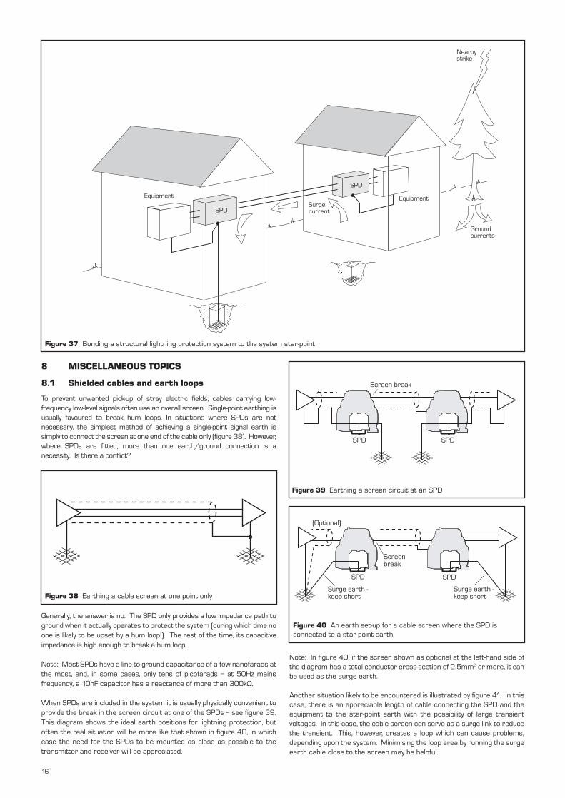
To prevent unwanted pick-up of stray electric fields, cables carrying low-frequency low-level signals often use an overall screen. Single-point earthing isusually favoured to break hum loops. In situations where SPDs are notnecessary, the simplest method of achieving a single-point signal earth issimply to connect the screen at one end of the cable only (figure 38). However,where SPDs are fitted, more than one earth/ground connection is anecessity. Is there a conflict?
Generally, the answer is no. The SPD only provides a low impedance path toground when it actually operates to protect the system (during which time noone is likely to be upset by a hum loop!). The rest of the time, its capacitiveimpedance is high enough to break a hum loop.
Note: Most SPDs have a line-to-ground capacitance of a few nanofarads atthe most, and, in some cases, only tens of picofarads – at 50Hz mainsfrequency, a 10nF capacitor has a reactance of more than 300kΩ.
When SPDs are included in the system it is usually physically convenient toprovide the break in the screen circuit at one of the SPDs – see figure 39.This diagram shows the ideal earth positions for lightning protection, butoften the real situation will be more like that shown in figure 40, in whichcase the need for the SPDs to be mounted as close as possible to thetransmitter and receiver will be appreciated.
Figure 38 Earthing a cable screen at one point only
Note: In figure 40, if the screen shown as optional at the left-hand side ofthe diagram has a total conductor cross-section of 2.5mm2 or more, it canbe used as the surge earth.
Another situation likely to be encountered is illustrated by figure 41. In thiscase, there is an appreciable length of cable connecting the SPD and theequipment to the star-point earth with the possibility of large transientvoltages. In this case, the cable screen can serve as a surge link to reducethe transient. This, however, creates a loop which can cause problems,depending upon the system. Minimising the loop area by running the surgeearth cable close to the screen may be helpful.
Screen break
SPD SPD
Figure 39 Earthing a screen circuit at an SPD
(Optional)
SPD SPD
Surge earth - keep short
Screen break
Surge earth - keep short
Figure 40 An earth set-up for a cable screen where the SPD isconnected to a star-point earth
16
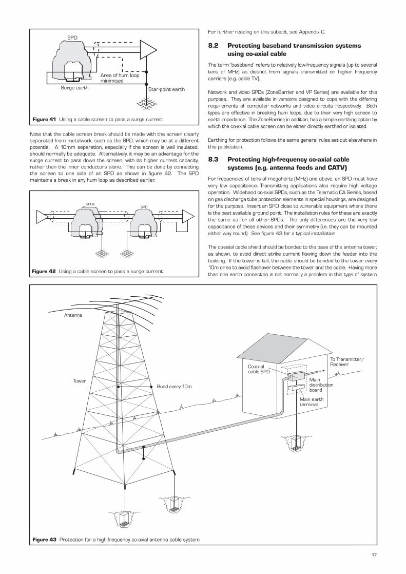
Note that the cable screen break should be made with the screen clearlyseparated from metalwork, such as the SPD, which may be at a differentpotential. A 10mm separation, especially if the screen is well insulated,should normally be adequate. Alternatively, it may be an advantage for thesurge current to pass down the screen, with its higher current capacity,rather than the inner conductors alone. This can be done by connectingthe screen to one side of an SPD as shown in figure 42. The SPDmaintains a break in any hum loop as described earlier.
SPD
Area of hum loop minimised
Surge earth Star-point earth
SPDsSPD
Figure 41 Using a cable screen to pass a surge current
Figure 42 Using a cable screen to pass a surge current
For further reading on this subject, see Appendix C.
8.2 Protecting baseband transmission systems using co-axial cable
The term ‘baseband’ refers to relatively low-frequency signals (up to severaltens of MHz) as distinct from signals transmitted on higher frequencycarriers (e.g. cable TV).
Network and video SPDs (ZoneBarrier and VP Series) are available for thispurpose. They are available in versions designed to cope with the differingrequirements of computer networks and video circuits respectively. Bothtypes are effective in breaking hum loops, due to their very high screen toearth impedance. The ZoneBarrier, in addition, has a simple earthing option bywhich the co-axial cable screen can be either directly earthed or isolated.
Earthing for protection follows the same general rules set out elsewhere inthis publication.
8.3 Protecting high-frequency co-axial cable systems (e.g. antenna feeds and CATV)
For frequencies of tens of megahertz (MHz) and above, an SPD must havevery low capacitance. Transmitting applications also require high voltageoperation. Wideband co-axial SPDs, such as the Telematic CA Series, basedon gas discharge tube protection elements in special housings, are designedfor the purpose. Insert an SPD close to vulnerable equipment where thereis the best available ground point. The installation rules for these are exactlythe same as for all other SPDs. The only differences are the very lowcapacitance of these devices and their symmetry (i.e. they can be mountedeither way round). See figure 43 for a typical installation.
The co-axial cable shield should be bonded to the base of the antenna tower,as shown, to avoid direct strike current flowing down the feeder into thebuilding. If the tower is tall, the cable should be bonded to the tower every10m or so to avoid flashover between the tower and the cable. Having morethan one earth connection is not normally a problem in this type of system
Antenna
TowerBond every 10m
Co-axial cable SPD
To Transmitter/ Receiver
Main distribution board
Main earth terminal
Figure 43 Protection for a high-frequency co-axial antenna cable system
17
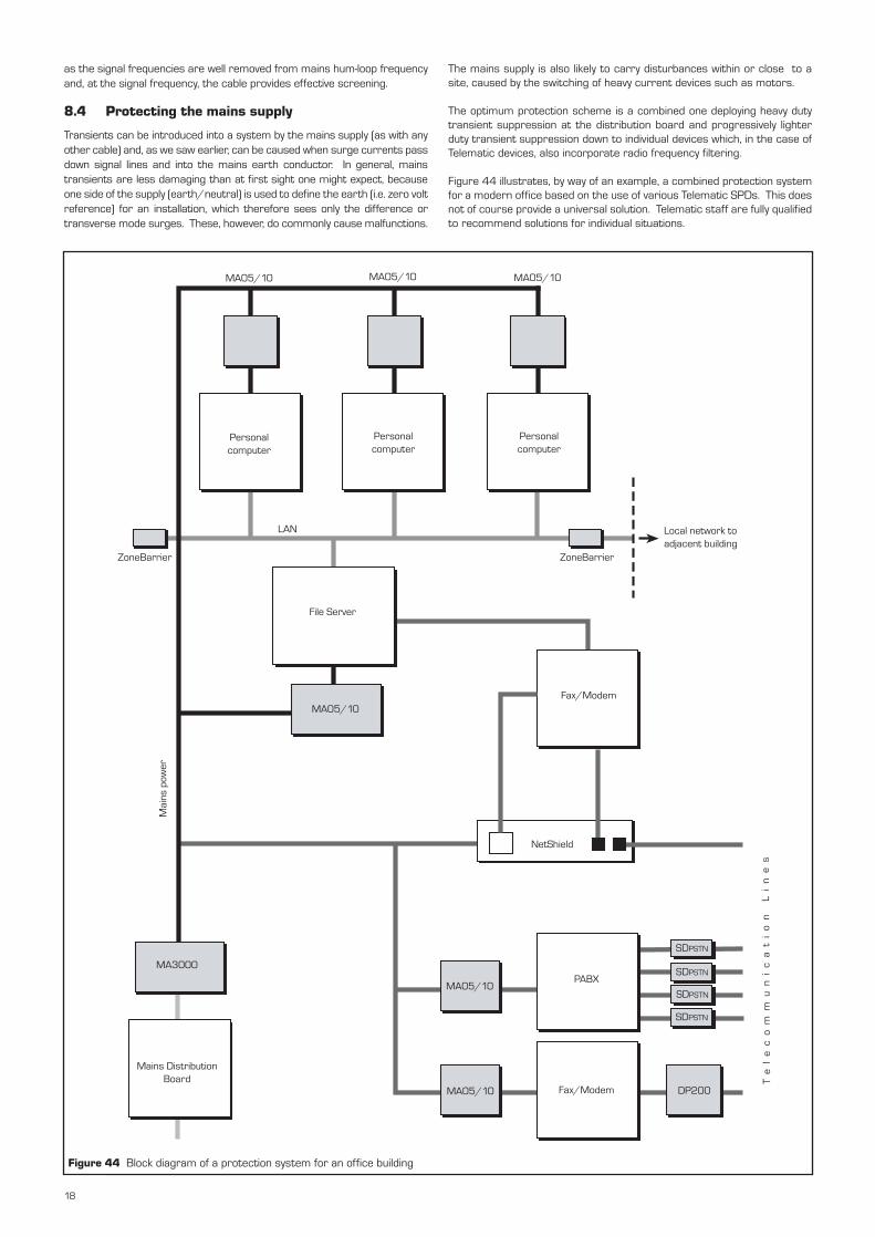
as the signal frequencies are well removed from mains hum-loop frequencyand, at the signal frequency, the cable provides effective screening.
8.4 Protecting the mains supply
Transients can be introduced into a system by the mains supply (as with anyother cable) and, as we saw earlier, can be caused when surge currents passdown signal lines and into the mains earth conductor. In general, mainstransients are less damaging than at first sight one might expect, becauseone side of the supply (earth/neutral) is used to define the earth (i.e. zero voltreference) for an installation, which therefore sees only the difference ortransverse mode surges. These, however, do commonly cause malfunctions.
The mains supply is also likely to carry disturbances within or close to asite, caused by the switching of heavy current devices such as motors.
The optimum protection scheme is a combined one deploying heavy dutytransient suppression at the distribution board and progressively lighterduty transient suppression down to individual devices which, in the case ofTelematic devices, also incorporate radio frequency filtering.
Figure 44 illustrates, by way of an example, a combined protection systemfor a modern office based on the use of various Telematic SPDs. This doesnot of course provide a universal solution. Telematic staff are fully qualifiedto recommend solutions for individual situations.
MA05/10 MA05/10 MA05/10
Personal computer
Personal computer
Personal computer
LAN
File Server
Local network to adjacent building
MA05/10Fax/Modem
NetShield
MA3000
Mains Distribution Board
Mai
ns p
ower
Te
le
co
mm
un
ic
at
io
n
Li
ne
s
MA05/10
MA05/10
PABX
Fax/Modem
SDPSTN
SDPSTN
SDPSTN
SDPSTN
DP200
ZoneBarrier ZoneBarrier
Figure 44 Block diagram of a protection system for an office building
18
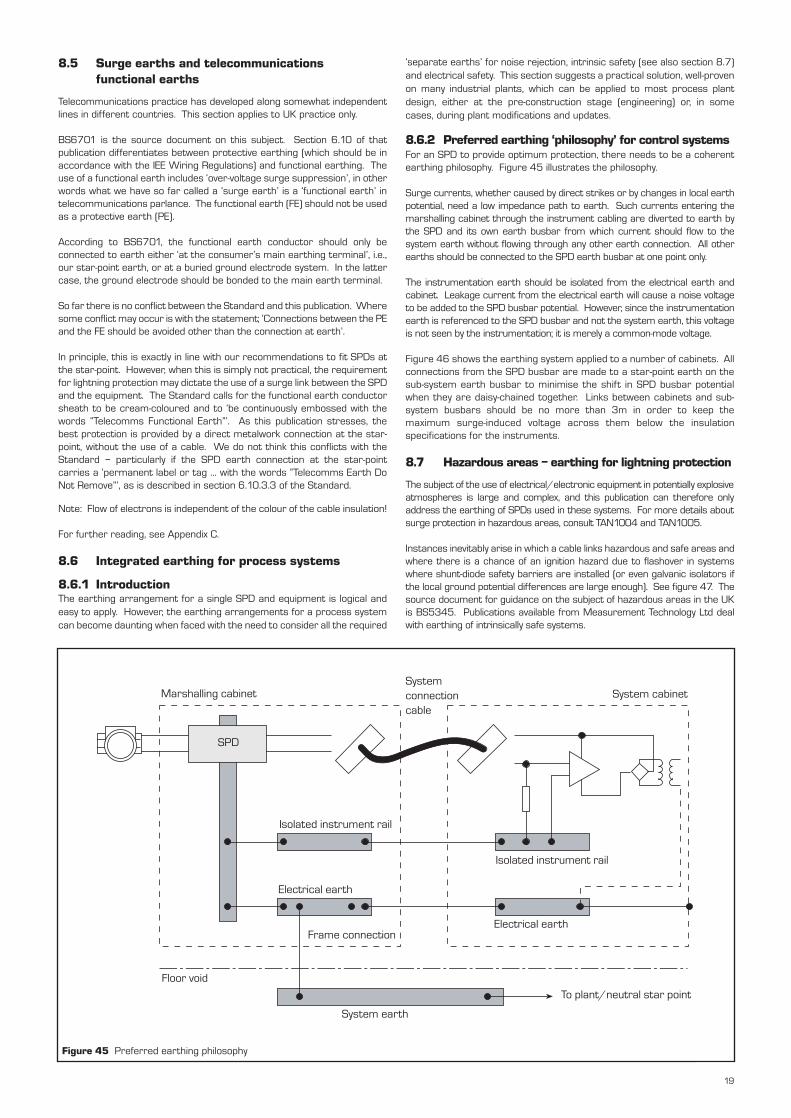
8.5 Surge earths and telecommunications functional earths
Telecommunications practice has developed along somewhat independentlines in different countries. This section applies to UK practice only.
BS6701 is the source document on this subject. Section 6.10 of thatpublication differentiates between protective earthing (which should be inaccordance with the IEE Wiring Regulations) and functional earthing. Theuse of a functional earth includes ‘over-voltage surge suppression’, in otherwords what we have so far called a ‘surge earth’ is a ‘functional earth’ intelecommunications parlance. The functional earth (FE) should not be usedas a protective earth (PE).
According to BS6701, the functional earth conductor should only beconnected to earth either ‘at the consumer’s main earthing terminal’, i.e.,our star-point earth, or at a buried ground electrode system. In the lattercase, the ground electrode should be bonded to the main earth terminal.
So far there is no conflict between the Standard and this publication. Wheresome conflict may occur is with the statement; ‘Connections between the PEand the FE should be avoided other than the connection at earth’.
In principle, this is exactly in line with our recommendations to fit SPDs atthe star-point. However, when this is simply not practical, the requirementfor lightning protection may dictate the use of a surge link between the SPDand the equipment. The Standard calls for the functional earth conductorsheath to be cream-coloured and to ‘be continuously embossed with thewords “Telecomms Functional Earth”’. As this publication stresses, thebest protection is provided by a direct metalwork connection at the star-point, without the use of a cable. We do not think this conflicts with theStandard – particularly if the SPD earth connection at the star-pointcarries a ‘permanent label or tag ... with the words “Telecomms Earth DoNot Remove”’, as is described in section 6.10.3.3 of the Standard.
Note: Flow of electrons is independent of the colour of the cable insulation!
For further reading, see Appendix C.
8.6 Integrated earthing for process systems
8.6.1 IntroductionThe earthing arrangement for a single SPD and equipment is logical andeasy to apply. However, the earthing arrangements for a process systemcan become daunting when faced with the need to consider all the required
‘separate earths’ for noise rejection, intrinsic safety (see also section 8.7)and electrical safety. This section suggests a practical solution, well-provenon many industrial plants, which can be applied to most process plantdesign, either at the pre-construction stage (engineering) or, in somecases, during plant modifications and updates.
8.6.2 Preferred earthing ‘philosophy’ for control systems For an SPD to provide optimum protection, there needs to be a coherentearthing philosophy. Figure 45 illustrates the philosophy.
Surge currents, whether caused by direct strikes or by changes in local earthpotential, need a low impedance path to earth. Such currents entering themarshalling cabinet through the instrument cabling are diverted to earth bythe SPD and its own earth busbar from which current should flow to thesystem earth without flowing through any other earth connection. All otherearths should be connected to the SPD earth busbar at one point only.
The instrumentation earth should be isolated from the electrical earth andcabinet. Leakage current from the electrical earth will cause a noise voltageto be added to the SPD busbar potential. However, since the instrumentationearth is referenced to the SPD busbar and not the system earth, this voltageis not seen by the instrumentation; it is merely a common-mode voltage.
Figure 46 shows the earthing system applied to a number of cabinets. Allconnections from the SPD busbar are made to a star-point earth on thesub-system earth busbar to minimise the shift in SPD busbar potentialwhen they are daisy-chained together. Links between cabinets and sub-system busbars should be no more than 3m in order to keep themaximum surge-induced voltage across them below the insulationspecifications for the instruments.
8.7 Hazardous areas – earthing for lightning protection
The subject of the use of electrical/electronic equipment in potentially explosiveatmospheres is large and complex, and this publication can therefore onlyaddress the earthing of SPDs used in these systems. For more details aboutsurge protection in hazardous areas, consult TAN1004 and TAN1005.
Instances inevitably arise in which a cable links hazardous and safe areas andwhere there is a chance of an ignition hazard due to flashover in systemswhere shunt-diode safety barriers are installed (or even galvanic isolators ifthe local ground potential differences are large enough). See figure 47. Thesource document for guidance on the subject of hazardous areas in the UKis BS5345. Publications available from Measurement Technology Ltd dealwith earthing of intrinsically safe systems.
Marshalling cabinetSystem connection cable
System cabinet
Isolated instrument rail
Isolated instrument rail
Electrical earth
Electrical earth
Floor void
System earth
To plant/neutral star point
Frame connection
SPD
Figure 45 Preferred earthing philosophy
19
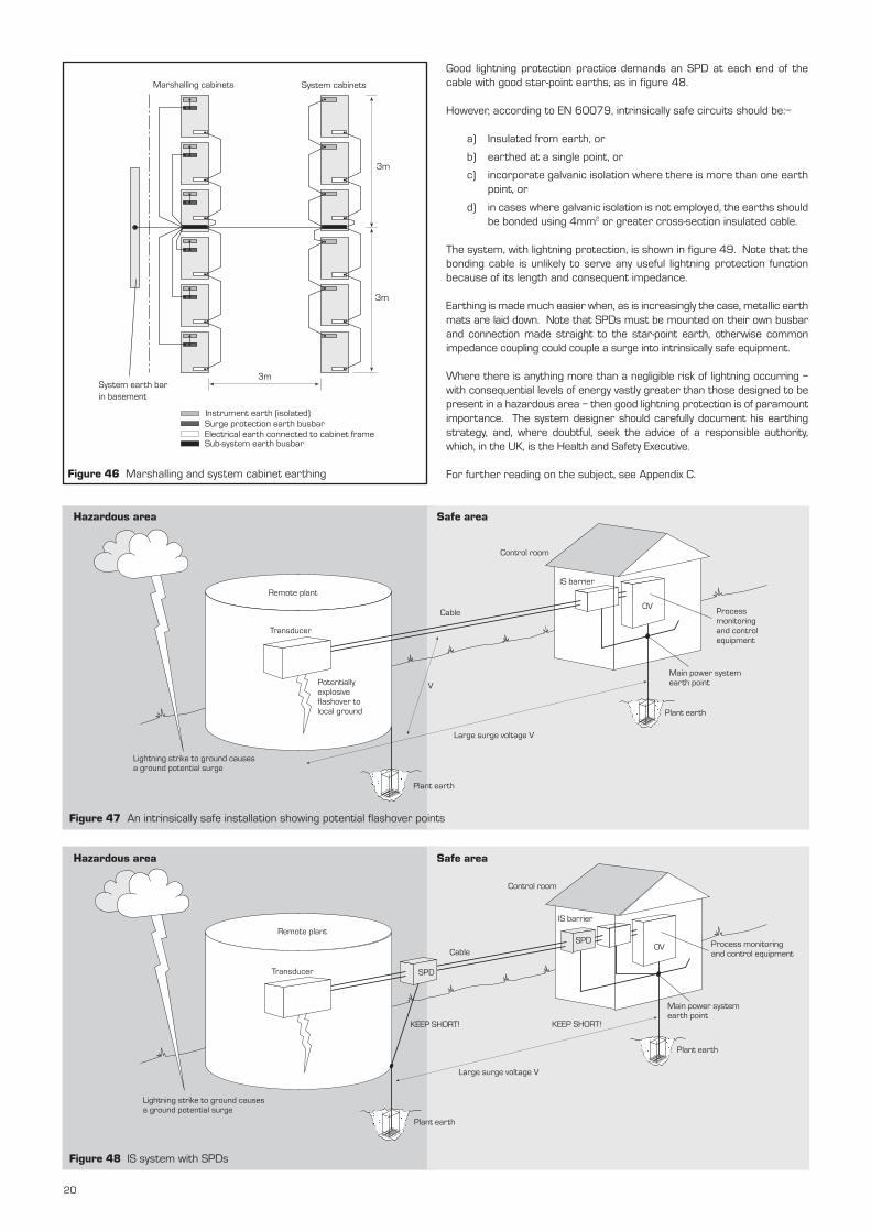
Remote plant
Lightning strike to ground causes a ground potential surge
Plant earth
Potentially explosive flashover to local ground
Cable
Large surge voltage V
Control room
IS barrier
OVProcess monitoring and control equipment
Main power system earth point
Plant earth
V
Transducer
Remote plant
Transducer
Lightning strike to ground causes a ground potential surge
Plant earth
KEEP SHORT! KEEP SHORT!
Process monitoring and control equipment
Main power system earth point
Plant earth
Large surge voltage V
SPD
CableSPD
IS barrier
OV
Control room
Marshalling cabinets System cabinets
System earth bar in basement
3m
3m
3m
Instrument earth (isolated)Surge protection earth busbarElectrical earth connected to cabinet frameSub-system earth busbar
Figure 46 Marshalling and system cabinet earthing
Good lightning protection practice demands an SPD at each end of thecable with good star-point earths, as in figure 48.
However, according to EN 60079, intrinsically safe circuits should be:–
a) Insulated from earth, or
b) earthed at a single point, or
c) incorporate galvanic isolation where there is more than one earthpoint, or
d) in cases where galvanic isolation is not employed, the earths shouldbe bonded using 4mm2 or greater cross-section insulated cable.
The system, with lightning protection, is shown in figure 49. Note that thebonding cable is unlikely to serve any useful lightning protection functionbecause of its length and consequent impedance.
Earthing is made much easier when, as is increasingly the case, metallic earthmats are laid down. Note that SPDs must be mounted on their own busbarand connection made straight to the star-point earth, otherwise commonimpedance coupling could couple a surge into intrinsically safe equipment.
Where there is anything more than a negligible risk of lightning occurring –with consequential levels of energy vastly greater than those designed to bepresent in a hazardous area – then good lightning protection is of paramountimportance. The system designer should carefully document his earthingstrategy, and, where doubtful, seek the advice of a responsible authority,which, in the UK, is the Health and Safety Executive.
For further reading on the subject, see Appendix C.
Hazardous area
Figure 47 An intrinsically safe installation showing potential flashover points
Figure 48 IS system with SPDs
Hazardous area Safe area
Safe area
20
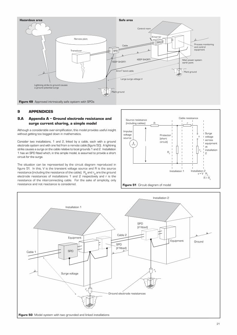
Remote plant
Transducer
Lightning strike to ground causes a ground potential surge
Plant ground
KEEP SHORT!KEEP SHORT!
Process monitoring and control equipment
Main power system earth point
Plant ground
Large surge voltage V
SPD
CableSPD
IS barrier
Control room
4mm2 bond cable
Figure 49 Approved intrinsically safe system with SPDs
9 APPENDICES
9.A Appendix A – Ground electrode resistance and surge current sharing, a simple model
Although a considerable over-simplification, this model provides useful insightwithout getting too bogged down in mathematics.
Consider two installations, 1 and 2, linked by a cable, each with a groundelectrode system and with one fed from a remote cable (figure 50). A lightningstrike causes a surge on the cable relative to local grounds 1 and 2. Installation1 has an SPD fitted which, in this simple model, is assumed to provide a shortcircuit for the surge.
The situation can be represented by the circuit diagram reproduced infigure 51. In this, V is the transient voltage source and R is the sourceresistance (including the resistance of the cable). Rg and rg are the groundelectrode resistances of installations 1 and 2 respectively and r is theresistance of the interconnecting cable. For the sake of simplicity, onlyresistance and not reactance is considered.
Source resistance (including cables)
Cable resistance
Impulse voltage source
R
Protector (short circuit)
Rg
r
Surge voltage across equipment at installation 2
v
rg
Installation 1 Installation 2v = V Rg
R + Rg
Figure 51 Circuit diagram of model
Installation 1
Installation 2
Equipment
SPDCable 1
Surge voltage
Ground electrode resistances
rg
SPD (if fitted)
Cable 2
SPD (if fitted)
Equipment Ground
rg
Figure 50 Model system with two grounded and linked installations
Hazardous area Safe area
21
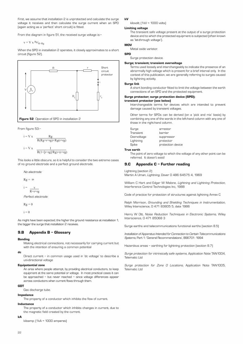
First, we assume that installation 2 is unprotected and calculate the surgevoltage it receives and then calculate the surge current when an SPD(again acting as a ‘perfect’ short circuit) is fitted.
From the diagram in figure 51, the received surge voltage is:–
v = V x Rg/R+Rg
When the SPD in installation 2 operates, it closely approximates to a shortcircuit (figure 52).
From figure 53:–
i = V x Rg R(Rg+r+rg)+Rg(r+rg)
i = V x 1R(1+[r+rg]/Rg)+(r+rg)
This looks a little obscure, so it is helpful to consider the two extreme casesof no ground electrode and a perfect ground electrode.
No electrode:
Rg =
i = vR+r+rg
Perfect electrode:
Rg = 0
i = 0
As might have been expected, the higher the ground resistance at installation 1,the bigger the surge that installation 2 receives.
9.B Appendix B – Glossary
BondingMaking electrical connections, not necessarily for carrying current butwith the intention of ensuring a common potential
dcDirect current – in common usage used in ‘dc voltage’ to describe auni-directional voltage
Equipotential zoneAn area where people attempt, by providing electrical conductors, to keepequipment at the same potential or voltage. In most practical cases it canbe approached – but never reached – since voltage differences appearacross conductors when current flows through them.
GDTGas discharge tube.
ImpedanceThe property of a conductor which inhibits the flow of current.
InductanceThe property of a conductor which inhibits changes in current, due tothe magnetic field created by the current.
kAkiloamp; (1kA = 1000 amperes)
Rg rg
i
Short circuit protector
rR
V
Figure 52 Operation of SPD in installation 2
kVkilovolt; (1kV = 1000 volts)
Limiting voltageThe transient safe voltage present at the output of a surge protectiondevice and to which the protected equipment is subjected (often knownas ‘let-through voltage’).
MOVMetal oxide varistor.
SPDSurge protection device.
Surge; transient; transient overvoltageTerms used loosely and interchangeably to indicate the presence of anabnormally high voltage which is present for a brief interval only. In thecontext of this publication, we are generally referring to surges causedby lightning activity.
Surge linkA short bonding conductor fitted to limit the voltage between the earthconnections of an SPD and the protected equipment.
Surge protector; surge protection device (SPD); transient protector (see below)
Interchangeable terms for devices which are intended to preventdamage caused by transient voltages.
Other terms for SPDs can be derived (on a ‘pick and mix’ basis) bycombining any one of the words in the left-hand column with any one ofthose in the right-hand column.
Surge arrestorTransient barrierOvervoltage suppressorLightning protectorSpike protection device
True earthThe point of zero voltage to which the voltage of any other point can bereferred. It doesn’t exist!
9.C Appendix C – Further reading
Lightning (section 2)Martin A Uman, Lightning, Dover 0 486 64575 4, 1969
William C Hart and Edgar W Malone, Lightning and Lightning Protection,Interference Control Technologies Inc, 1988
Code of practice for protection of structures against lightning Annex C
Ralph Morrison, Grounding and Shielding Techniques in Instrumentation,Wiley Interscience, 0 471 83805 5, date 1986
Henry W Ott, Noise Reduction Techniques in Electronic Systems, WileyInterscience, 0 471 85068 3
Surge earths and telecommunications functional earths (section 8.5)
Installation of Apparatus Intended for Connection to Certain TelecommunicationsSystems, Part 1: ‘General Recommendations’, BS6701: 1994
Hazardous areas – earthing for lightning protection (section 8.7)
Surge protection for intrinsically safe systems, Application Note TAN1004,Telematic Ltd
Surge protection for Zone 0 Locations, Application Note TAN1005,Telematic Ltd
8
22

991
-113
02Telematic Limited
Pondwicks Road, Luton, Beds, UK LU1 3LHTel: +44 (0)1582 429464 Fax: +44 (0)1582 459669E-mail: [email protected] WWW: www.telematic.com
A member of the MTL Instruments Group plc
Atlantic Scientific Corporation4300 Fortune Place, Suite A, W. Melbourne, Florida 32904 USA
Tel: +1 321 725 8000 Fax: +1 321 727 0736E-mail: [email protected] WWW: www.atlanticscientific.com
A member of the MTL Instruments Group plc