mt2000 multichannel bitstream analyzer user guide · mt2000 multichannel bitstream analyzer . user...
TRANSCRIPT

1
MT2000 Multichannel Bitstream Analyzer User Guide
MT2000 version 0.0.31 and later
User Guide version 0.9 Linear Acoustic 108 Foxshire Drive Lancaster, PA 17601 (717) 735-3611 phone (717) 735-3612 fax
L14/1/18083

2
Warranty Information DISCLAIMER OF WARRANTIES: Products manufactured by Linear Acoustic are warranted against defects in material and workmanship for a period of five (5) years from the date of purchase. The internal battery used in the MT2000 is warranted for a period of 90 days from the date of purchase. THERE ARE NO OTHER IMPLIED OR EXPRESS WARRANTIES AND NO WARRANTY FOR MERCHANTABILITY OR FITNESS FOR A PARTICULAR PURPOSE. During the warranty period Linear Acoustic Inc. will repair, or at our discretion replace, components which prove to be defective, provided the unit is returned, shipped pre-paid to us directly with a return authorization (RA) number clearly marked on the packaging. Please note, this RA number must be present or package will be refused and returned to sender. All requests for repairs MUST include the unit serial number to ensure quick and accurate service. DEFECTS CAUSED BY UNAUTHORIZED MODIFICATIONS, MISUSE OR ACCIDENTS, UNAUTHORIZED CUSTOMER REPAIRS, OR ANY FURTHER DAMAGE CAUSED BY INADEQUATE PACKAGING FOR SERVICE RETURN ARE NOT COVERED BY THIS WARRANTY. PLEASE SAVE THE SHIPPING CARTON AND ALL PACKING MATERIALS. FAILURE TO RETURN UNIT IN ORIGINAL SHIPPING CARTON AND PACKING MATERIALS WILL RESULT IN A CHARGE FOR NEW SHIPPING MATERIALS. LIMITATION OF PERIOD OF ACTION ON CONTRACT: No action, regardless of form, arising out of the transactions under this agreement may be brought by buyer, its successors, agents and/or assigns, more than three years from date of purchase. LIMITATION OF LIABILITY: It is understood and agreed that Linear Acoustic’s liability whether in contract, in tort, under any warranty, in negligence or otherwise shall not exceed the cost of repair or replacement of the defective components and under no circumstances shall Linear Acoustic be liable for incidental, special, direct, indirect or consequential damages, or loss of use, revenue or profit even if Linear Acoustic or its agents have been advised, orally or in writing, of the possibility of such damages. Linear Acoustic, the “LA” symbol, are trademarks or registered trademarks of Linear Acoustic Inc. This product optionally contains technologies from Dolby Laboratories. Dolby and the double-D symbol are trademarks of Dolby Laboratories. All other trademarks remain the property of their respective owners.

3
Table of Contents Chapter 1: Introduction............................................................................................................................. 7
1.1. Introduction ....................................................................................................................................... 7
1.2. Warranty and Feedback ............................................................................................................... 7
Chapter 2: Overview and Connections............................................................................................... 8
2.1. Unpacking and Inspection ........................................................................................................... 8
2.2. Unit Overview.................................................................................................................................... 8
2.2.1. Front panel ................................................................................................................................ 8
2.2.2. Bottom ......................................................................................................................................... 9
2.3. Connections ..................................................................................................................................... 10
2.3.1. Rear Panel ............................................................................................................................... 10
2.3.1.1. Power Connection ...................................................................................................... 10
2.3.1.2. AES Input ........................................................................................................................ 10
2.3.1.3. AES Output .................................................................................................................... 10
2.3.1.4. SDI Input ......................................................................................................................... 11
2.3.1.5. SDI Output ..................................................................................................................... 11
2.3.1.6. TOSLINK® Input ........................................................................................................ 11
2.3.1.7. TOSLINK Output ......................................................................................................... 11
2.3.1.8. VRef Input ...................................................................................................................... 11
2.3.1.9. HDMI Input .................................................................................................................... 11
2.3.2. Side Panel ................................................................................................................................ 12
2.3.2.1. Headphone Output .................................................................................................... 12
2.3.2.2. Ethernet Connection ................................................................................................. 12
2.3.2.3. USB Connector ............................................................................................................. 12
Chapter 3: Detailed Operation ............................................................................................................ 13
3.1. Interface ............................................................................................................................................ 13
3.2. Joystick Encoder............................................................................................................................ 13
3.2.1. Joystick Operations (Status / Control Window) ..................................................... 13
3.2.2. Joystick Operations (Loudness / Volume Window) ............................................... 13
3.3. Display ............................................................................................................................................... 14
3.3.1. Display Window ........................................................................................................................ 14
3.3.2. Status / Control Window ...................................................................................................... 14
3.3.3. Loudness / Volume Window .............................................................................................. 16
Display ................................................................................................................................................... 16

4
Volume Control.................................................................................................................................. 16
3.4. Operation .......................................................................................................................................... 17
3.4.1. Power On / Off ........................................................................................................................... 17
3.4.2. Menu Structure and Navigation ........................................................................................ 18
The menu structure for the MT2000 is very straight forward and simple to navigate even though there are many options and parameters able to be adjusted. The menu structure is organized into logical submenus............................................................................... 18
3.4.3. Top Menu ..................................................................................................................................... 18
3.4.3.1. Input Status Display .................................................................................................. 19
3.4.3.2. Audio Meter Display ................................................................................................. 20
3.4.3.3. Loudness and Dolby Metadata Display ............................................................ 21
3.4.3.4. AES / SMPTE stream status display .................................................................. 21
3.4.3.5. Statistics Menu............................................................................................................. 21
3.4.3.6. Setup Menu .................................................................................................................... 22
3.4.3.7. Version Number .......................................................................................................... 23
3.5. Setup Menu – In Detail ............................................................................................................... 24
3.5.1. Presets Submenu ...................................................................................................................... 24
3.5.1.1. Presets ............................................................................................................................. 25
3.5.1.2. Preset Name .................................................................................................................. 28
3.5.1.3. Copy Preset ................................................................................................................... 28
3.5.2. I/O Submenu .............................................................................................................................. 29
3.5.2.1. Main Output Source .................................................................................................. 29
3.5.2.2. Downmix Type............................................................................................................. 30
3.5.2.3. SDI Embed Audio ........................................................................................................ 30
3.5.2.4. SDI Output 1/2 Source - SDI Output 15/16 Source ................................... 30
3.5.2.5. SDI Validity Bit ............................................................................................................. 31
3.5.2.6. SDI Audio Bit................................................................................................................. 31
3.5.2.7. Idle Screen Dim ........................................................................................................... 31
3.5.3. MADI Output Submenu ......................................................................................................... 31
3.5.3.1. Enable MADI Output ................................................................................................. 32
3.5.3.2. MADI Output 1/2 Source - MADI Output 15/16 Source .......................... 32
3.5.4. Loudness Meter Submenu ................................................................................................... 32
3.5.4.1. Loudness Mode............................................................................................................ 33
3.5.4.2. 10 seconds Speech Gate .......................................................................................... 33

5
3.5.4.3. Main Loudness Meter Integration (Main Loud Type) .............................. 34
3.5.4.4. Secondary Loudness Meter Integration (Sec Loud Type) ...................... 34
3.5.4.5. Floating Bar Graphical Loudness Meter (Graph Loud Type) ................ 34
3.5.4.6. Loudness Log Integration Time (Log Loud Type) ...................................... 35
3.5.4.7. Loudness Logging Frequency (Log Frequency) .......................................... 35
3.5.5. Signal Generator Submenu .................................................................................................. 35
3.5.5.1. Generated Stream ...................................................................................................... 35
3.5.5.2. PCM Generator Frequency – Left channel ...................................................... 36
3.5.5.3. PCM Generator Frequency – Right channel ................................................... 36
3.5.5.4. PCM Generator Amplitude – Left channel ...................................................... 36
3.5.5.5. PCM Generator Amplitude – Right channel ................................................... 37
3.5.5.6. PCM Channel Select ................................................................................................... 37
3.5.5.7. PCM Frequency Sweep – Minimum Frequency ........................................... 37
3.5.5.8. PCM Frequency Sweep – Maximum Frequency........................................... 38
3.5.5.9. PCM Frequency Sweep Time ................................................................................ 38
3.5.6. File Playout Submenu ............................................................................................................ 38
3.5.6.1. PCM File Stream .......................................................................................................... 39
3.5.6.2. DD File Stream ............................................................................................................. 39
3.5.6.3. Dolby E File Stream ................................................................................................... 40
3.5.6.4. Dolby Digital Plus File Stream .............................................................................. 41
3.5.6.5. File Playback Amplitude – Left channel .......................................................... 43
3.5.6.6. File Playback Amplitude – Right channel ....................................................... 43
3.5.7. Tests Submenu .......................................................................................................................... 44
3.5.7.1. Activate Test ................................................................................................................. 44
3.5.7.2. Beep Flash Test ........................................................................................................... 44
3.5.7.3. Audio Latency Test .................................................................................................... 44
3.5.7.4. Audio Latency Status ................................................................................................ 45
3.5.8. Video Generator Submenu................................................................................................... 45
3.5.8.1. SDI Video Generator Enable .................................................................................. 45
3.5.8.2. SDI Video Standard .................................................................................................... 46
3.5.8.3. Ignore Dolby E Guard band Video (Ignore DE GB Vid) ............................ 46
3.5.8.4. Dolby E Guard Band Video Reference (DE GB Video Ref) ...................... 46
3.5.8.5. Dolby E Line Position – NTSC (DE GB Line NTSC) .................................... 46
3.5.8.6. Dolby E Line Position – PAL (DE GB Line PAL) .......................................... 47

6
3.5.8.7. Dolby E Line Position – 720p (DE GB Line 720p)...................................... 47
3.5.8.8. Dolby E Line Position – 1080 (DE GB Line 1080)...................................... 48
3.5.9. Alerts Submenu ......................................................................................................................... 48
3.5.9.1. Alerts Status Display ................................................................................................. 49
3.5.9.2. Alert When (1-4) ........................................................................................................ 49
3.5.9.3. Alert Threshold (1-4) ............................................................................................... 50
3.5.9.4. Alert On Delay (1-4) .................................................................................................. 50
3.5.9.5. Alert Off Delay (1-4) .................................................................................................. 50
3.5.10. Communication Submenu ............................................................................................... 50
3.5.10.1. Communication Status Display ....................................................................... 51
3.5.10.2. Use DHCP ................................................................................................................... 51
3.5.10.3. Static IP Address .................................................................................................... 51
3.5.10.4. Static Netmask ........................................................................................................ 51
3.5.10.5. Static Gateway ......................................................................................................... 52
3.5.10.6. MAC Address ............................................................................................................ 52
3.5.11. System Submenu ................................................................................................................. 52
3.5.11.1. Set to Defaults.......................................................................................................... 52
3.5.11.2. Maintenance File Upload.................................................................................... 53
3.5.11.3. Device Options File Upload ............................................................................... 53
3.5.11.4. Restore Old Device Options .............................................................................. 53
4. Problems and Possible Causes ................................................................................................... 54
4.1 Unit won’t power on ............................................................................................................... 54
4.2 Volume Control does not work.......................................................................................... 54
4.3 Unit does not recognize the input signal ...................................................................... 54
4.4 Cannot change test generator or file playback settings. ....................................... 54
4.5 SDI output stream does not contain signals generated by the MT2000 ....... 54
Chapter 5: Specifications ....................................................................................................................... 55
5.1. Physical.............................................................................................................................................. 55
5.2. Electrical ........................................................................................................................................... 55
5.3. Audio................................................................................................................................................... 56
5.4. Other ................................................................................................................................................... 57

7
Chapter 1: Introduction
1.1. Introduction Congratulations on your purchase of the Linear Acoustic MT2000 bitstream analyzer! The MT2000 is capable of analyzing, monitoring, and measuring the loudness of audio signals carried in many commonly used broadcast interfaces such as AES-3, SDI (both HD- and SD-), TOSLINK® optical, and optionally DVB-ASI transport streams, MADI, and HDMI. PCM and optionally Dolby® E, Dolby Digital (also called AC-3), and Dolby Digital Plus (also called E-AC-3) are supported. The MT2000 is capable of measuring the loudness of audio input signals following the ITU BS.1770 standard and using Dolby Dialogue Intelligence where applicable. The MT2000 is also capable of generating audio test signals, playing back pre-encoded Dolby bitstreams, performing certain audio tests such as audio latency, and generating A/V sync Flash-Beep signals. A built in video signal generator is available for generating SDI output test streams. Utility functions such as SDI de-embedding, embedding, pair shuffling, Dolby decoding (optional) and downmixing are also supported by the MT2000. You will quickly see that this unit is as useful to any audio engineer as a digital multimeter is to an electrician!
1.2. Warranty and Feedback Please take a moment to fill out the postage-paid warranty card included with the unit and drop it in the mail. This will enable us to contact you if there are any software or documentation issues. Additionally, if this is your first Linear Acoustic product or you have not already registered for a user account on our website, please do so. Software updates and the latest documentation are always available there, at your convenience, 24/7/365. Please visit www.linearacoustic.com and click on the “register” button at the top Also, we are very interested in your feedback. This unit was designed based on input gathered from many broadcast engineers and it will evolve further thanks to ongoing suggestions and comments from users. We look forward to hearing from you!

8
Chapter 2: Overview and Connections
2.1. Unpacking and Inspection Before unpacking the unit, inspect the outer carton for shipping damage. If the carton shows damage, inspect the unit in those areas. Please save the carefully designed shipping carton and packing materials. In the unlikely event that the unit needs to be returned to the factory, alternate cartons or packing materials may not be adequate and can cause damage not covered by warranty. The following essential items are provided with the unit: • Shipping/Carrying case • Power supply with an IEC power cord (style matches country of order) • Quick-start sheet to get you up and running • USB memory stick containing documentation including this manual • USB to RS-485 adapter • micro BNC to standard BNC adapter • a handy black pen. • Warranty information: Please fill out and return the warranty card to Linear
Acoustic to ensure your software and documentation are kept up to date.
2.2. Unit Overview This section introduces you to MT2000 and its views:
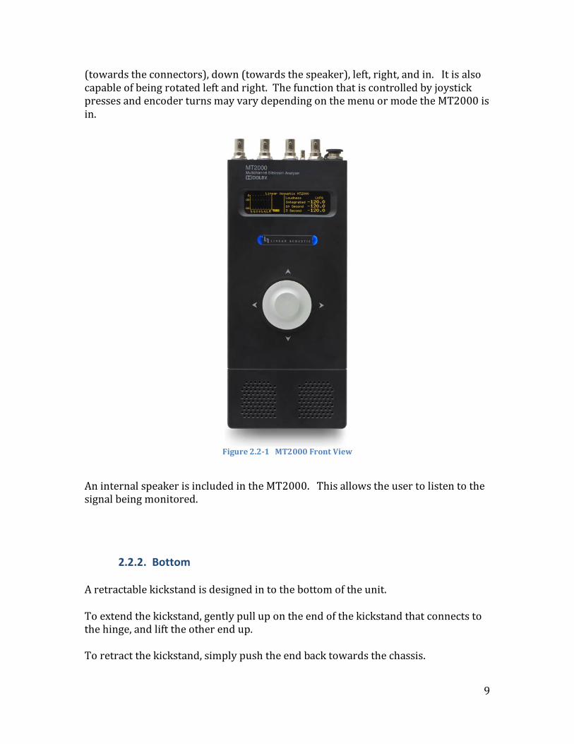
2.2.1. Front panel On the front panel of the MT2000, you will find from the top down:
• OLED display • backlit Linear Acoustic logo and power indicator • joystick/encoder • internal speaker
The OLED display provides the user with visual feedback and interaction as to what the MT2000 is doing, parameter settings, and input signal status. The LED backlit Linear Acoustic logo acts as a power indicator. The LEDs glow red as the unit initializes, and then turn to blue as the unit operates normally. MT2000 includes a joystick/encoder on the front panel. All adjustments and parameter settings are made with this control. It is capable of being pressed up
9
(towards the connectors), down (towards the speaker), left, right, and in. It is also capable of being rotated left and right. The function that is controlled by joystick presses and encoder turns may vary depending on the menu or mode the MT2000 is in.
Figure 2.2-1 MT2000 Front View
An internal speaker is included in the MT2000. This allows the user to listen to the signal being monitored.
2.2.2. Bottom A retractable kickstand is designed in to the bottom of the unit. To extend the kickstand, gently pull up on the end of the kickstand that connects to the hinge, and lift the other end up. To retract the kickstand, simply push the end back towards the chassis.

10
2.3. Connections This chapter covers all connections
2.3.1. Rear Panel The rear panel of the MT2000 contains the majority of the connections which will be used.
Figure 2-2 MT2000 rear panel
2.3.1.1. Power Connection A DC power input with weatherproof plug is provided. This accepts a 12 V DC input, and is used to power the unit and charge the internal battery. The center post is the positive terminal and the sleeve is ground. The sleeve is threaded and the provided power supply includes a locking ring to ensure that the power connection does not accidentally become undone.
2.3.1.2. AES Input AES-3id signals are accepted via the 75-ohm BNC connector. Consumer formatted signals (IEC 60958 or S/PDIF) signals are also accepted at this input. If the MADI option is enabled, MADI signals are input via this connection.
2.3.1.3. AES Output Audio signals formatted to the AES-3id standard are output via the AES output. If the MADI option is enabled, MADI signals are output via this connection.

11
2.3.1.4. SDI Input An autosensing SD/HD-SDI input is included on the MT2000. It allows access to all 16 audio channels in the SDI stream for analysis, monitoring, decoding, de-embedding, and pair shuffling. The SDI input is also used for DVB-ASI input streams, when the DVB-ASI option is enabled.
2.3.1.5. SDI Output An SD/HD-SDI output is included on the MT2000. All 16 audio channels in the SDI stream are available for embedding and channel shuffling. The SDI output is also used for outputting DVB-ASI streams, when the DVB-ASI option is enabled.
2.3.1.6. TOSLINK® Input Consumer formatted signals (IEC 60958 or S/PDIF) signals are accepted at this optical input. PCM and Dolby® Digital streams are accepted at this input.
Note!
ADAT streams are not supported via the TOSLINK connections.
2.3.1.7. TOSLINK Output PCM and Dolby Digital consumer formatted signals (IEC 60958 or S/PDIF) signals are capable of being output from this optical output.
2.3.1.8. VRef Input Analog Vertical Reference (VRef) is accepted via the micro BNC connector. This input allows for guard band measurement of Dolby E streams.
2.3.1.9. HDMI Input An optional HDMI input is available to aid in the testing of complete broadcast systems, allowing connection to consumer devices such as Set Top Boxes and digital televisions. The use of this input
Note!
Only PCM, Dolby Digital (AC-3) and Dolby Digital Plus (E-AC-3) streams are supported via the HDMI connection.

12
2.3.2. Side Panel The rear panel of the UPMAX v4
Figure 2-3 MT2000 Side View
2.3.2.1. Headphone Output A stereo 1/8” (~3.5 mm) stereo headphone jack is included. This tip/ring/sleeve connector accepts most headphones, and is wired tip = left, ring = right, sleeve = shield. When headphones are plugged in to this connector, the internal speaker is muted.
2.3.2.2. Ethernet Connection A standard Ethernet connector is included. The function of this connector is reserved for future use.
2.3.2.3. USB Connector A USB input is included. This is used for software upgrades.
13
Chapter 3: Detailed Operation
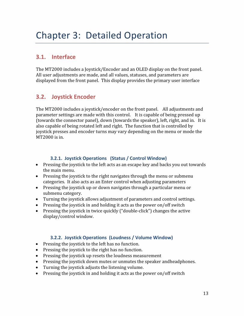
3.1. Interface The MT2000 includes a Joystick/Encoder and an OLED display on the front panel. All user adjustments are made, and all values, statuses, and parameters are displayed from the front panel. This display provides the primary user interface
3.2. Joystick Encoder The MT2000 includes a joystick/encoder on the front panel. All adjustments and parameter settings are made with this control. It is capable of being pressed up (towards the connector panel), down (towards the speaker), left, right, and in. It is also capable of being rotated left and right. The function that is controlled by joystick presses and encoder turns may vary depending on the menu or mode the MT2000 is in.
3.2.1. Joystick Operations (Status / Control Window) • Pressing the joystick to the left acts as an escape key and backs you out towards
the main menu. • Pressing the joystick to the right navigates through the menu or submenu
categories. It also acts as an Enter control when adjusting parameters • Pressing the joystick up or down navigates through a particular menu or
submenu category. • Turning the joystick allows adjustment of parameters and control settings. • Pressing the joystick in and holding it acts as the power on/off switch • Pressing the joystick in twice quickly (“double-click”) changes the active
display/control window.
3.2.2. Joystick Operations (Loudness / Volume Window) • Pressing the joystick to the left has no function. • Pressing the joystick to the right has no function. • Pressing the joystick up resets the loudness measurement • Pressing the joystick down mutes or unmutes the speaker andheadphones. • Turning the joystick adjusts the listening volume. • Pressing the joystick in and holding it acts as the power on/off switch

14
• Pressing the joystick in twice quickly (“double-click”) changes the active display/control window.
3.3. Display
3.3.1. Display Window The MT2000 includes an OLED display on the front panel. This display provides the primary user interface
Figure 3.3.1-1 Main Display Screen
The display is divided into two windows:
• The Status / Control Window occupies the left half of the display. • The Loudness / Volume Control Window occupies the right.
Only one of these windows may be controlled at a time. The active window is highlighted with a yellow bar at the top. In the image shown above, the Status and Control Window is the active window. To change which window is active, press the joystick encoder in rapidly two times (double-click).
3.3.2. Status / Control Window

15
Figure 3.3.2-1 Status/Control Window
The Status / Control Window display changes depending on which menu, submenu, or display is currently chosen. At the top of this window, there is some information that is always displayed regardless of which menu is in use. The name of the active preset is always displayed in the top left corner. To the right of the Active Preset display is an icon which displays the status of the speaker and headphone output.
• An icon which looks like a speaker is displayed when the speaker/headphone outputs are active.
• when the speaker/headphone outputs are muted, the following icon is displayed:
To the right of the speaker status is an icon which indicates whether the MT2000 is being operated from AC Power (Mains Line) or from the internal battery.
• An icon which looks like a battery is displayed when the unit is being powered from its internal battery.
• when the unit is being run from the AC Line Power (Mains input), the following icon is displayed:

16
To the right of the power source indicator is the battery charge display. This displays the charge level of the internal battery in percentage.
3.3.3. Loudness / Volume Window
Display The right half of the OLED display always displays the loudness of the audio program,
Figure 3.3.3-1 Loudness/Volume Window
This window displays information regarding the: • Input audio type
• PCM • Dolby E (DE) • Dolby Digital (DD) • Dolby Digital Plus (DD+)
• Audio program configuration (Dolby E) • Program being monitored (Dolby E) • Dolby dialog normalization (dialnorm) value • Main loudness level and integration time • Secondary loudness level and integration time
Volume Control

17
Since the volume control determines the loudness level of the signal being applied directly to your ears, it’s only logical that in the loudness window is where you would be allowed to control this function, right? Our development team thought so, so this is where we decided to put it. When the Loudness Window is active, the joystick encoder adjusts the volume of the internal speaker or headphone outputs, as well as mute/unmute of those outputs. To adjust the volume of the speaker or headphones, turn the joystick encoder left or right. A pop-up window appears and displays the level of the volume control:
Figure 3.3.3-2 Volume Control Display
To mute or unmute the speaker / headphones, press the encoder down (towards the speaker). The icon in the Status / Control Menu will change accordingly, and a Mute or Unmute message will temporarily be displayed.
Figure 3.3.3-3 Speaker Mute/Unmute Display
3.4. Operation
3.4.1. Power On / Off To power the MT2000 on, press the encoder knob in and hold it. Within a couple of seconds the LEDs behind the Linear Acoustic logo will briefly light up red, and then change to blue as the unit continues to boot. It takes several seconds for the unit to run through its boot up routine, self-diagnostics, and be ready to accept audio. Once the OLED display shows the home screen, the unit is ready for use.

18
Figure 3-6 Home Screen
The process to turn the MT2000 off is similar. Press the encoder in and hold it until the unit shuts off.
3.4.2. Menu Structure and Navigation
The menu structure for the MT2000 is very straight forward and simple to navigate even though there are many options and parameters able to be adjusted. The menu structure is organized into logical submenus
Figure 3-7 Menu Tree
3.4.3. Top Menu The top menu allows for the display of important information about the input stream in a very quick and easy to find manner. From within the top level menu, it is also possible to get to statistics and setup menus, along with determining the software release version of the MT2000.

19
Figure 3-8 Top Level Menu
The top menu level includes selections for: • Input status • Audio Meters (home screen) • Loudness and Dolby metadata parameters • AES / SMPTE header status • Statistics • Setup • Software release version Many of the menu options include sub-menus or sub-displays. These displays and menus are described in the following sections.
3.4.3.1. Input Status Display This window displays information regarding the input signal.
Figure 3-9 Input Status Display
There are several sub-windows in this display which include information about:
• Audio input status • SMPTE 337M input status

20
• SDI video status • SDI Audio status • Dolby E status • MADI status • Audio Latency Test status
To navigate through the various display windows, press the joystick encoder up or down. Pressing the joystick encoder to the left acts as an escape key and jumps the display back to the Audio Input Status window at the very top.
3.4.3.2. Audio Meter Display This screen displays the audio levels for the given audio program or decoded audio stream if the audio format is a Dolby format.
This window also includes a floating bar display. The floating bar displays the measured loudness of the selected program, along with the integration time constant used for the measurement in a box at the end of the bar. The available integration time constants are:
• 10s 10 seconds • 3 s 3 seconds • MOM Momentary (400 ms integration time) • TP True-Peak • INTG Integrated
To change the loudness measurement integration time for this display, rotate the encoder knob left or right. If the audio source is a Dolby coded format, a second floating bar will appear on the display. This bar indicates the dialnorm value contained in the bitstream. It is labeled with a “DN” in the box.

21
3.4.3.3. Loudness and Dolby Metadata Display This menu displays the loudness measurement type, and loudness values for all the supported time constants. If Dolby Dialog Intelligence is enabled, the percentage of measured speech is also displayed. If the audio source is a Dolby coded format, the Dolby metadata is displayed as well.
To change the loudness values or metadata parameters being displayed on the screen, rotate the encoder knob left or right.
3.4.3.4. AES / SMPTE stream status display The AES Status window displays information about the input AES stream.
To change the value being displayed on the screen, rotate the encoder knob left or right.
3.4.3.5. Statistics Menu

22
This Menu displays statistics and information about the MT2000. Information regarding:
• Product Options • Alert settings and values • Dolby CAT1100 card • How long the MT2000 has been running, and the time of the last reference
change are all available in this menu
To navigate through the various display windows, press the joystick encoder up or down. Pressing the joystick encoder to the left acts as an escape key and jumps the display back to the main Statistics Menu option at the top menu level.
3.4.3.6. Setup Menu The Setup Menu is where all configuration settings for the MT2000 are made

23
The setup menu contains multiple submenus, with parameters and settings organized into logical subgroups. There are submenus for:
• Presets • I/O • MADI Out • Loudness Meter • Signal Generator • File Playout • Tests • Video Generator • Alerts • IP Communication • System Settings
The Setup Menu, its submenus, and the parameters/controls contained within are described in detail the section 6 below.
3.4.3.7. Version Number The MT2000 version number and firmware (FPGA) version numbers are available from the top menu.

24
To view the Firmware version number press the joystick encoder down one time.
3.5. Setup Menu – In Detail The Setup menu options, submenus, and parameter definitions are described in the following sections:
3.5.1. Presets Submenu The Presets Menu is where user presets can be recalled, modified, stored, named, and copied. Within the Presets menu, there are menu options for:
• Preset (16 possible locations) • Preset Parameters • Preset Name • Copy Preset

25
3.5.1.1. Presets The MT2000 is capable of storing up to 16 user defined and adjustable presets. The unit ships from the factory with several presets pre-loaded into the unit, which include:
• AES Input • TOSLINK input • SDI Input (Group 1, Channels 1/2) • SDI Input (Group 1, Channels 1/2) • MADI Input (Group 1, Channels 1/2) • Internal Reference clock • MADI Input (Group 1, Channels 1/2)
Plus an additional 9 empty preset locations The factory presets loaded into the unit may be overwritten. The parameters which are stored within a preset include:
3.5.1.1.1. Processor Input Source This selects the input source used to monitor and measure loudness of. The available options for this are:
• AES In * • SDI In 5/6 • TOSLINK In • SDI In 7/8 • HDMI In • SDI In 9/10 • MADI In • SDI In 11/12 • SDI In 1/2 • SDI In 13/14

26
• SDI In 3/4 • SDI In 15/16
* indicates the default value
3.5.1.1.2. MADI Input Group ** This menu selects the MADI Group to have a pair selected from for monitoring and measuring. The options are:
• Group 1 * • Group 5 • Group 2 • Group 6 • Group 3 • Group 7 • Group 4 • Group 8
* indicates the default value ** requires the MADI option to be enabled
Note!
MADI streams should be input and output via the AES connections.
3.5.1.1.3. MADI Input Channel Pair ** When the MADI option is enabled, this menu allows the selection of the channel pair within the MADI Group, selected above, that is being monitored. The options are:
• Ch 1/2 * • Ch 5/6 • Ch 3/4 • Ch 7/8
* indicates the default value ** requires the MADI option to be enabled
3.5.1.1.4. HDMI Input Channel Pair ** When the HDMI option is enabled, this menu allows the selection of the channel pair from the HDMI connection to be monitored. The options are:
• PCM Ch 1/2 * • SPDIF Ch 1/2 • PCM Ch 3/4 • SPDIF Ch 3/4 • PCM Ch 5/6 • SPDIF Ch 5/6 • PCM Ch 7/8 • SPDIF Ch 7/8

27
* indicates the default value ** requires the HDMI option to be enabled
3.5.1.1.5. Clock Source The control allows selection of the reference clock source used by the MT2000. The available options are:
• AES Input * • TOSLINK • HDMI • MADI • SDI • VRef • Internal 48KHz
* indicates the default value
3.5.1.1.6. DVB-ASI ** The control allows selection of DVB-ASI input streams for monitoring and analysis. the reference clock source used by the MT2000. The available options are:
• Enable • Disable *
* indicates the default value ** requires the DVB-ASI option to be enabled
Note!
DVB-ASI streams should be input and output via the SDI connections.
3.5.1.1.7. DVB-ASI PID This control allows selection of the audio PID in the DVB-ASI stream to monitor
• 0x0010
3.5.1.1.8. SRC Bypass The MT2000 includes sample rate converters on the input to the audio measurement circuitry. This control allows the asynchronous sample rate converters used on the input to the MT2000 to be bypassed. The options are:

28
• Enable (SRCs bypassed) • Disable * (SRCs in circuit)
* indicates the default value
3.5.1.1.9. Apply DD/+ DRC ** This control allows for the selection of dynamic range compression during the Dolby Digital or Dolby Digital Plus decode. The available options for this are:
• dialnorm * Dialnorm only • Line Mode + Dn Dialnorm with Line Mode Compression • RF Mode + Dn Dialnorm with RF Mode Compression
* indicates the default value ** requires the Dolby Decode or DVB-ASI option to be enabled
3.5.1.1.10. Apply DE DRC ** This control allows for the selection of dynamic range compression during the Dolby Digital or Dolby Digital Plus decode. The available options for this are:
• Bypass * No Dynamic Range Compression or dialnorm applied • dialnorm Dialnorm only • Line Mode + Dn Dialnorm with Line Mode Compression • RF Mode + Dn Dialnorm with RF Mode Compression
* indicates the default value ** requires the Dolby Decode or DVB-ASI option to be enabled
3.5.1.2. Preset Name Each Preset includes a 15-character preset name. Presets are able to be named or renamed to something meaningful and intuitive. To name a preset: Press the encoder to the left or to the right to select the space to update. Rotate the encoder left or right to select the desired character. Once the preset name has been changed to the desired name, keep pressing the encoder to the right through all the spaces to accept the change in the name.
3.5.1.3. Copy Preset The MT2000 allows users to copy preset information from another preset into the current working preset.

29
To copy a preset: Enter the “Copy Preset” menu and press the joystick / encoder down. The display will show “Copy From Preset” and the current preset name. rotate the joystick/encoder until the desired preset to be copied is found, then press the joystick to the right to accept it.
3.5.2. I/O Submenu The I/O submenu is where audio input and output options that are not stored in presets or are related to MADI Outputs are controlled.
3.5.2.1. Main Output Source The main output source is the audio being monitored at the speaker and headphone outputs, as well as being output at the AES, TOSLINK, and optionally SDI and MADI outputs. The choices for the main output source are:
• Downmix * • SDI input • Signal Generator • TOSLINK input • File Playout • SDI Input 7/8 • MADI Input • SDI Input 9/10 • SDI Input 1/2 • SDI Input 11/12 • SDI Input 3/4 • SDI Input 13/14 • SDI Input 5/6 • SDI Input 15/16
* indicates the default value

30
The downmix option is a downmix of the main program being decoded and monitored. If the audio program contains more than 2-channels, it will be downmixed to stereo for your listening pleasure.
3.5.2.2. Downmix Type The downmix type being performed by the MT2000 for the Main Output is selectable and is stored as part of a preset. The available choices are:
• LtRt * Left Total / Right Total. A Dolby Surround encoded format • LoRo Left Only / Right Only. No phase shift information in the
surround channels. Recommended for headphone monitoring and mono downmixes
• Auto Based upon preferred downmix metadata values contained in a Dolby bitstream
* indicates the default value
3.5.2.3. SDI Embed Audio This control determines whether audio is being embedded into the SDI output or simply passed through from the SDI input. The choices are:
• Enable • Disable *
* indicates the default value
3.5.2.4. SDI Output 1/2 Source - SDI Output 15/16 Source The following 8 parameter settings select the audio source to be embedded into the various audio pairs in an HD/SD-SDI stream. The default value is that the same input pair is matched to the same output pair. Example: SDI 1/2 input is routed to SDI 1/2 output. The available output source options are:
• SDI Input 1/2 • SDI Input 15/16 • SDI Input 3/4 • Muted • SDI Input 5/6 • Main Output • SDI Input 7/8 • AES Input • SDI Input 9/10 • TOSLINK Input • SDI Input 11/12 • Signal Generator • SDI Input 13/14 • File Playout

31
3.5.2.5. SDI Validity Bit
Reserved for future use.
3.5.2.6. SDI Audio Bit
Reserved for future use.
3.5.2.7. Idle Screen Dim The OLED screen automatically dims after sitting idle for approximately 2.5 minutes. Dim values vary from 6% (nearly off) to 100% (full brightness), with the default value being 87%.
3.5.3. MADI Output Submenu This submenu determines the behavior of the MADI output. MADI channels 1-16 aer duplicated for MADI output channels 17-32, 33-48, and 49-64.

32
3.5.3.1. Enable MADI Output The following 8 parameter settings select the audio source to be embedded into the various audio pairs in an HD/SD-SDI stream. The default value is the same input pair matched to the output pair. The available output source options are:
• Enable • Disable *
* indicates the default value
3.5.3.2. MADI Output 1/2 Source - MADI Output 15/16 Source The following parameter settings select the audio source to be embedded into the first 8 audio pairs (16-channels) in a MADI stream. The default value is the same input pair (1-4) matched to the output pair (1-4 and 5-8) . The available output source options are:
• MADI Input 1/2 • Main Output • MADI Input 3/4 • AES Input • MADI Input 5/6 • TOSLINK Input • MADI Input 7/8 • Signal Generator • Muted • File Playout
* indicates the default value
3.5.4. Loudness Meter Submenu This submenu allows the configuration of the loudness meters used in the MT2000

33
3.5.4.1. Loudness Mode This menu allows the loudness measurement mode to be selected. Loudness estimation is performed based on the ITU BS.1770 standard. The available loudness mode options are:
• BS1770-1 ITU BS.1770-1 • BS1770-1+D ITU BS.1770-1 + Dolby Dialog Intelligence • Leq(A) Leq A scale • Leq(A) + D Leq A scale + Dolby Dialog Intelligence • BS1770-2 ITU BS.1770-2 • BS1770-2 + D * ITU BS.1770-2 + Dolby Dialog Intelligence *
* indicates the default value
3.5.4.2. 10 seconds Speech Gate This menu allows the speech gating for the 10 second loudness measurement window to either run continuously or to stop and hold when speech is not detected. The available loudness mode options are:
• Continuous * • Hold Non-Speech
* indicates the default value

34
3.5.4.3. Main Loudness Meter Integration (Main Loud Type) This menu allows the loudness measurement mode for the main loudness meter to be selected. Different integration times and True-Peak measurement are selectable. The available loudness mode options are:
• Integrated Loudness measurement * • 10 Second Loudness measurement • 3 Second Loudness measurement • Momentary Loudness measurement • Maximum True-Peak
* indicates the default value
3.5.4.4. Secondary Loudness Meter Integration (Sec Loud Type) This menu allows the loudness measurement mode for the secondary loudness meter to be selected. Different integration times and True-Peak measurement are selectable. The available loudness mode options are:
• Integrated Loudness measurement * • 10 Second Loudness measurement • 3 Second Loudness measurement • Momentary Loudness measurement • Maximum True-Peak
* indicates the default value
3.5.4.5. Floating Bar Graphical Loudness Meter (Graph Loud Type) This menu allows the loudness measurement mode for the floating bar loudness meter, shown on the audio meter display, to be selected. Different integration times and True-Peak measurement are selectable. The available loudness mode options are:
• Integrated Loudness measurement * • 10 Second Loudness measurement • 3 Second Loudness measurement • Momentary Loudness measurement • Maximum True-Peak
* indicates the default value

35
3.5.4.6. Loudness Log Integration Time (Log Loud Type) Reserved for future use.
3.5.4.7. Loudness Logging Frequency (Log Frequency) Reserved for future use.
3.5.5. Signal Generator Submenu The MT2000 includes a 2-channel PCM signal generator to aid in troubleshooting and calibrating systems. The two channels are capable of being operated and configured individually for both frequency and amplitude, or linked together.
The parameters and controls in the Signal Generator submenu are:
3.5.5.1. Generated Stream This parameter controls the function of the PCM test tones generator. It allows for presets to be selected or for custom settings controlled by the user. The available settings are:
• PCM 400Hz -20 dBFS * Preset 400 Hz tone at -20 dBFS in both Left and Right channels
• PCM 1KHz -20 dBFS Preset 1 KHz tone at -20 dBFS in both Left and Right channels
• PCM 5KHz -20 dBFS Preset 5 KHz tone at -20 dBFS in both Left and Right channels
• PCM Silence Preset Silence in both Left and Right channels • PCM Custom Allows for user adjustable frequency and amplitude
in both the Left and Right channels • PCM FSwp 20-12K Preset frequency sweep at -20 dBFS in both Left and

36
Right channels • PCM FSwp Custom Allows for user adjustable frequency sweep
* indicates the default value
Note!
For any of the following parameters in the Signal Generator submenu to be active, the Generated Stream parameter must be set to PCM Custom or PCM FSwp Custom.
3.5.5.2. PCM Generator Frequency – Left channel This parameter controls the frequency being generated for the Left channel of the Test Tone output pair. The available frequency range is:
• 20 Hz – 1 KHz in 10 Hz increments • 1 KHz – 20 KHz in 100 Hz increments
The default frequency setting is 400 Hz.
3.5.5.3. PCM Generator Frequency – Right channel This parameter controls the frequency being generated for the Right channel of the Test Tone output pair. The available frequency range is:
• Follow Left Channel • 20 Hz – 1 KHz in 10 Hz increments • 1 KHz – 20 KHz in 100 Hz increments
The default frequency setting is to Follow Left Channel setting.
3.5.5.4. PCM Generator Amplitude – Left channel This parameter controls the amplitude of the signal generator for the Left channel of the Test Tone output. This control affects both the steady test tone and the frequency sweep.

37
The available amplitude control range is:
• 0 dBFS to -60 dBFS in 1 dB increments • Silence
The default setting is -20 dBFS.
3.5.5.5. PCM Generator Amplitude – Right channel This parameter controls the amplitude of the signal generator for the Right channel of the Test Tone output. This control affects both the steady test tone and the frequency sweep. The available amplitude control range is:
• Follow Left channel • 0 dBFS to -60 dBFS in 1 dB increments • Silence
The default setting is to Follow Left Channel setting.
3.5.5.6. PCM Channel Select This control allows the selection of which channel to populate with audio when using the signal generator. The choices are:
• Left Channel • Right Channel • Both Channels *
* indicates the default value
3.5.5.7. PCM Frequency Sweep – Minimum Frequency This parameter controls the minimum frequency generated for the Frequency Sweep signal. The available frequency range is:
• 20 Hz – 1 KHz in 10 Hz increments • 1 KHz – 19.9 KHz in 100 Hz increments
The default frequency setting is 20 Hz.

38
3.5.5.8. PCM Frequency Sweep – Maximum Frequency This parameter controls the maximum frequency generated for the Frequency Sweep signal. The available frequency range is:
• 30 Hz – 1 KHz in 10 Hz increments • 1 KHz – 20 KHz in 100 Hz increments
The default frequency setting is 20 KHz.
3.5.5.9. PCM Frequency Sweep Time This parameter controls the length of time the frequency sweep signal takes to sweep from the minimum frequency to the maximum frequency. The control range is:
• 1 second through 10 seconds in 1 second increments
The default frequency setting is 5 seconds.
3.5.6. File Playout Submenu The MT2000 also includes the ability to play back audio test files. Most of these files are Dolby coded audio (Dolby E, Dolby Digital, Dolby Digital Plus), but a few PCM signals such as Pink Noise and White Noise are also available. One unique feature is that the MT2000 is capable of playing a test file simultaneously while generating PCM test tones.
Note!
In the File Playout submenu, the “ > “ symbol is displayed to the left of the name of the file being played, regardless if it is PCM, Dolby Digital, Dolby E, or Dolby Digital Plus

39
3.5.6.1. PCM File Stream This menu allows the loudness measurement mode for the loudness log to be selected. Different integration times and True-Peak measurement are selectable. The available loudness mode options are:
• Pink Noise • White Noise
Note!
The “ > “ symbol is displayed to the left of the file name indicates the file which is currently being played
3.5.6.2. DD File Stream This submenu allows the selection of a Dolby Digital (AC-3) bitstream to be played. There are many bitstreams to choose from, varying in channel configuration (acmod), test tone frequency, test tone amplitude, and data rates The file name for each test signal describes the signal itself. The guide to interpreting the contents of the file based on the name is as follows:
Filename: 2/0 256 K 400
2/0 Audio coding mode (acmod or channel configuration) 256 Data rate (kilobits per second or kbps)
K Amplitude 1k Test tone frequency (MT = multi-tone)

40
The Dolby Digital files for playback include:
1-channel streams • 1/0 96 K 100 • 1/0 96 K 1k • 1/0 96 K 5k • 1/0 96 K 12k • 1/0 96 K 400 2-channel streams • 2/0 192 K 100 • 2/0 192 K 1k • 2/0 192 K 5k • 2/0 192 K 12k • 2/0 192 K 400 • 2/0 256 K 100 • 2/0 256 K 1k • 2/0 256 K 5k • 2/0 256 K 12k • 2/0 256 K 400 5.1 and 5.0 channel streams • 3/2L 384 K 100 • 3/2L 448 K 100 • 3/2 384 K 100 • 3/2L 384 K 12k • 3/2L 448 K 12k • 3/2 384 K 12k • 3/2L 384 K 1k • 3/2L 448 K 1k • 3/2 384 K 1k • 3/2L 384 K 400 • 3/2L 448 K 400 • 3/2 384 K 400 • 3/2L 384 K 5k • 3/2L 448 K 5k • 3/2 384 K 5k • 3/2L 384 K MT • 3/2L 448 K MT • 3/2 448 K 100 • 3/2 448 K 1k • 3/2 448 K 5k • 3/2 448 K 12k • 3/2 448 K 400
3.5.6.3. Dolby E File Stream This submenu allows the selection of a Dolby E bitstream to be played. There are many bitstreams to choose from, varying in program configuration, video frame rate, test tone frequency, and test tone amplitude
The file name for each test signal describes the signal itself. The guide to interpreting the contents of the file based on the name is as follows:
Filename: 2+2 N20K 1k
2+2 Dolby E program configuration N NTSC frame rate (29.97 Hz), or “P” for PAL frame rate (25 Hz) 20 Bit depth of Dolby E frame (16- or 20-bit) K Amplitude
1k Test tone frequency (MT = multi-tone) The Dolby E files for playback include:
NTSC Streams PAL Streams • 2+2 N20K 100 • 2+2 P20K 100

41
• 2+2 N20K 12k • 2+2 P20K 12k • 2+2 N20K 1k • 2+2 P20K 1k • 2+2 N20K 400 • 2+2 P20K 400 • 2+2 N20K 5k • 2+2 P20K 5k 3X2 N16K 100 3X2 P16K 100 3X2 N16K 12k 3X2 P16K 12k 3X2 N16K 1k 3X2 P16K 1k 3X2 N16K 400 3X2 P16K 400 3X2 N16K 5k 3X2 P16K 5k • 5.1+2 N20K 100 • 5.1+2 P20K 100 • 5.1+2 N20K 12k • 5.1+2 P20K 12k • 5.1+2 N20K 1k • 5.1+2 P20K 1k • 5.1+2 N20K 400 • 5.1+2 P20K 400 • 5.1+2 N20K 5k • 5.1+2 P20K 5k 5.1 N16J MT 5.1 P16J MT 5.1 N16K 100 5.1 P16K 100 5.1 N16K 12k 5.1 P16K 12k 5.1 N16K 1k 5.1 P16K 1k 5.1 N16K 400 5.1 P16K 400 5.1 N16K 5k 5.1 P16K 5k 5.1 N16K MT 5.1 P16K MT 5.1 N20J MT 5.1 P20J MT 5.1 N20K MT 5.1 P20K MT • 8x1 N20K 100 • 8x1 P20K 100 • 8x1 N20K 12k • 8x1 P20K 12k • 8x1 N20K 1k • 8x1 P20K 1k • 8x1 N20K 400 • 8x1 P20K 400 • 8x1 N20K 5k • 8x1 P20K 5k
3.5.6.4. Dolby Digital Plus File Stream This submenu allows the selection of a Dolby Digital Plus (E-AC-3) bitstream to be played. There are many bitstreams to choose from, varying in channel configuration (acmod), test tone frequency, test tone amplitude, and data rates The file name for each test signal describes the signal itself. The guide to interpreting the contents of the file based on the name is as follows:
Filename: 2/0 256 K 400

42
2/0 Audio coding mode (acmod or channel configuration) 256 Data rate (kilobits per second or kbps)
K Amplitude (K = -20 dBFS) 1k Test tone frequency (MT = multi-tone)
The Dolby Digital Plus files for playback include:
2-channel streams • 2/0 96 K 100 • 2/0 128 K 100 • 2/0 256 K 1k L • 2/0 96 K 10k • 2/0 128 K 10k • 2/0 256 K 1k R • 2/0 96 K 1k • 2/0 128 K 12k • 2/0 96 K 400 • 2/0 128 K 1k • 2/0 96 K 5k • 2/0 128 K 400 • 2/0 96 K MT • 2/0 128 K 5k • 2/0 128 K MT 5.1 and 5.0 channel streams • 3-2L K 1k L • 3-2L K 1k C • 3-2L K 1k Ls • 3-2L K 1k R • 3-2L K 63 LFE • 3-2L K 1k Rs • 3/2L 192 K 100 • 3/2 192 K 100 • 3/2L 384 K 100 • 3/2L 192 K 10k • 3/2 192 K 10k • 3/2L 384 K 10k • 3/2L 192 K 1k • 3/2 192 K 1k • 3/2L 384 K 12k • 3/2L 192 K 400 • 3/2 192 K 400 • 3/2L 384 K 1k • 3/2L 192 K 5k • 3/2 192 K 5k • 3/2L 384 K 400 • 3/2L 192 K MT • 3/2 192 K MT • 3/2L 384 K 5k • 3/2L 384 K MT • 3/2L 256 K 100 • 3/2 256 K 100 • 3/2L 256 K 10k • 3/2 256 K 10k • 3/2 384 K 100 • 3/2L 256 K 1k • 3/2 256 K 1k • 3/2 384 K 10k • 3/2L 256 K 400 • 3/2 256 K 400 • 3/2 384 K 12k • 3/2L 256 K 5k • 3/2 256 K 5k • 3/2 384 K 1k • 3/2L 256 K MT • 3/2 256 K MT • 3/2 384 K 400 • 3/2 384 K 5k • 3/2 384 K MT 7.1-channel streams • 3-4L K 1k L • 3-4L K 1k Ls • 3-4L K 1k Lb • 3-4L K 1k R • 3-4L K 1k Rs • 3-4L K 1k Rb • 3-4L K 1k C • 3-4L K 63 LFE • 3-4L 384 K 100 • 3/4L 384 K 100 • 3-4L 576 K 10k • 3-4L 384 K 10k • 3-4L 384 K 10k

43
• 3-4L 384 K 1k • 3-4L 384 K 1k • 3-4L 640 K 10k • 3-4L 384 K 400 • 3-4L 384 K 400 • 3-4L 640 K 12k • 3-4L 384 K 5k • 3-4L 384 K 5k • 3-4L 384 K MT • 3-4L 384 K MT
3.5.6.5. File Playback Amplitude – Left channel This parameter controls the amplitude of the signal generator for the Left channel of the File Playback signal, when playing back one of the PCM files. The available amplitude control range is:
• 0 dBFS to -60 dBFS in 1 dB increments • Silence
The default setting is -20 dBFS.
Note!
This control only affects PCM file playback. It does not affect the level of any Dolby encoded test streams.
3.5.6.6. File Playback Amplitude – Right channel This parameter controls the amplitude of the signal generator for the Right channel of the File Playback signal, when playing back one of the PCM files. The available amplitude control range is:
• Follow Left channel • 0 dBFS to -60 dBFS in 1 dB increments • Silence
The default setting is to Follow Left Channel setting.
Note!
This control only affects PCM file playback. It does not affect the level of any Dolby encoded test streams.

44
3.5.7. Tests Submenu The MT2000 is capable of generating an Audio / Video synchronization test signal (Flash Beep) and performing an audio latency test. The tests submenu is where these tests are enabled and selected.
3.5.7.1. Activate Test This control allows for the desired test to be selected or disabled. The test options are:
• Off * • Beep Flash Test • Audio Latency Test
* indicates the default value
3.5.7.2. Beep Flash Test This test generates a white image that is 1-frame in length, once every 5 seconds. A short bust of PCM audio is output synchronous with the start of the white video frame. The format of the video being generated is adjusted via the controls in the Video submenu (section 6.8 below)
3.5.7.3. Audio Latency Test The MT2000 supports measuring the latency of devices and audio signal paths. It generates a PCM signal burst once every 5 seconds, and measures the amount of time it takes to be returned to the MT2000. This is a closed loop test where the MT2000 is both the test source and the test end point

45
3.5.7.4. Audio Latency Status This screen displays the measurement status of the audio latency test. The measured value can be displayed in either audio samples or in time. To change the display units between samples and time, press the joystick encoder to the right. The available Audio Latency test displays are:
• Latency measurement displayed in number of audio samples • Latency measurement Displayed in time • No Input No input audio is detected • No Burst In Input audio is detected, though the test signal
burst is not yet recognized
Note!
Because the audio test signal is output once every 5 seconds, it can take several seconds for the returned test signal to be recognized and the measurement calculated.
3.5.8. Video Generator Submenu The MT2000 is capable of generating video signals for the SDI output. The video format is selectable, along with the guard band timing when outputting Dolby E.
3.5.8.1. SDI Video Generator Enable This control enables the video generator. The available loudness mode options are:

46
• Enable • Disable *
* indicates the default value
3.5.8.2. SDI Video Standard This parameter allows the selection of the video format generated and used for the SDI output. The supported video standards are:
• 720p 50 Hz * • 1080p 23.98 Hz • 720p 59.94 Hz • 1080p 24 Hz • 720p 60 Hz • 1080p 25 Hz • 1080 sf 23.98 Hz • 1080p 29.97 Hz • 1080 sf 24 Hz • 1080p 30 Hz • 1080i 25 Hz • SD NTSC • 1080i 29.97 Hz • SD PAL • 1080i 30 Hz
* indicates the default value
3.5.8.3. Ignore Dolby E Guard band Video (Ignore DE GB Vid) This control allows for Dolby E test signals to be properly aligned with video reference or purposefully misaligned. The available options are:
• Yes * • No
* indicates the default value
3.5.8.4. Dolby E Guard Band Video Reference (DE GB Video Ref) This parameter selects the video reference source to align the Dolby E frames to when playing back Dolby E test files. The available reference options are:
• Analog VRef * • SDI
* indicates the default value
3.5.8.5. Dolby E Line Position – NTSC (DE GB Line NTSC) This parameter selects the line position / guard band timing for Dolby E test files referenced to the analog VRef signal. It is possible to adjust the timing of the Dolby E frame to any line (Line 1 through Line 524) in the NTSC frame.

47
The default value is Line 14, which is the ideal line position for Dolby E with this frame rate and reference. The available settings are:
• Line 1 through Line 524 • Line 14 *
* indicates the default value
3.5.8.6. Dolby E Line Position – PAL (DE GB Line PAL) This parameter selects the line position / guard band timing for Dolby E test files referenced to the analog VRef signal. It is possible to adjust the timing of the Dolby E frame to any line (Line 1 through Line 624) in the PAL frame.
The default value is Line 12, which is the ideal line position for Dolby E with this frame rate and reference.
The available settings are:
• Line 1 through Line 624 • Line 12 *
* indicates the default value
3.5.8.7. Dolby E Line Position – 720p (DE GB Line 720p) This parameter selects the line position / guard band timing for Dolby E test files referenced to the SDI signal. It is possible to adjust the timing of the Dolby E frame to any line (Line 1 through Line 750) in the video frame. The default value is Line 30, which is the ideal line position for Dolby E with this frame rate and reference.
The available settings are:
• Line 1 through Line 750 • Line 30 *
* indicates the default value

48
3.5.8.8. Dolby E Line Position – 1080 (DE GB Line 1080) This parameter selects the line position / guard band timing for Dolby E test files referenced to the SDI signal. It is possible to adjust the timing of the Dolby E frame to any line (Line 1 through Line 1125) in the video frame.
The default value is Line 24, which is the ideal line position for Dolby E with this frame rate and reference.
The available settings are:
• Line 1 through Line 1125 • Line 24 *
* indicates the default value
3.5.9. Alerts Submenu The MT2000 is able to monitor for certain conditions and alert the user if these conditions are true. Up to 4 simultaneous Alerts are supported.

49
3.5.9.1. Alerts Status Display This display shows the status of the 4 possible Alerts supported by the MT2000. For each Alert, there is a display for the number of occurrences of the trigger, the Alert type, Alert Threshold, and current value of the Alert.
3.5.9.2. Alert When (1-4) This control allows the function for triggering an alert to be selected for the 4 Alerts supported in the MT2000. The available Alert triggers are:
• Never * • Auto Channel Under • LKFS Over Threshold • Any Channel Over Threshold • LKFS Under Threshold • Reference Loss • Center Channel Threshold • Bitstream Error • Silence Detect
* indicates the default value

50
3.5.9.3. Alert Threshold (1-4) This control adjusts the threshold for audio level alerts. The control range is:
• 0 to -70 dBFS in 1 dB increments, -75 dB, -80 dB, -85 dB, Muted • -40 dBFS *
* indicates the default value
3.5.9.4. Alert On Delay (1-4) This control sets a delay on triggering the Alert. The Alert condition must be active for the amount of time the delay control is set to before the Alert is triggered. Using this control allows the Alert condition to momentary occur without triggering the Alert. An example of this is allowing the loudness measurement to momentarily cross the threshold. The control range for this parameter is:
• 0 – 20 seconds in 1 sec increments • 0 seconds *
* indicates the default value
3.5.9.5. Alert Off Delay (1-4) This control sets a delay on releasing the Alert once the condition has ceased. This control and the Alert On Delay control allow hysteresis to be added to the Alert function in order to prevent many annoying false triggers The control range for this parameter is:
• 0 – 10 seconds in 1 sec increments • 0 seconds *
* indicates the default value
3.5.10. Communication Submenu The communication submenu is where the IP communication settings are managed.
51
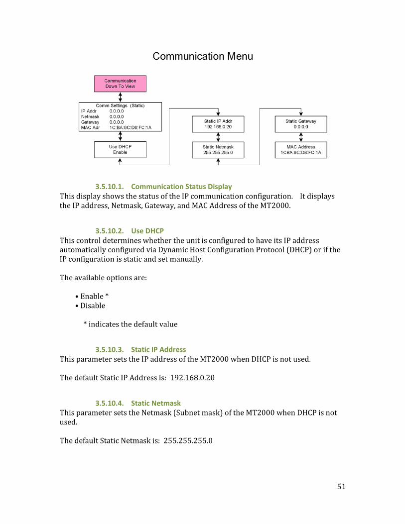
3.5.10.1. Communication Status Display This display shows the status of the IP communication configuration. It displays the IP address, Netmask, Gateway, and MAC Address of the MT2000.
3.5.10.2. Use DHCP This control determines whether the unit is configured to have its IP address automatically configured via Dynamic Host Configuration Protocol (DHCP) or if the IP configuration is static and set manually. The available options are:
• Enable * • Disable
* indicates the default value
3.5.10.3. Static IP Address This parameter sets the IP address of the MT2000 when DHCP is not used. The default Static IP Address is: 192.168.0.20
3.5.10.4. Static Netmask This parameter sets the Netmask (Subnet mask) of the MT2000 when DHCP is not used. The default Static Netmask is: 255.255.255.0

52
3.5.10.5. Static Gateway This parameter sets the default Gateway of the MT2000 when DHCP is not used. The default Static Gateway is: 0.0.0.0
3.5.10.6. MAC Address This window displays the unique MAC Address of the MT2000.
3.5.11. System Submenu The System Submenu is where settings are restored to their factory conditions, and the operating software / firmware is updated.
3.5.11.1. Set to Defaults This control allows a partial or complete factory reset. The available Return to Default options are:
• Set: IP Comm * Returns IP communication to factory default values • Set: UserPreset Returns the 16 User Preset settings to factory default
values • Set: I/O Returns I/O settings to factory default values • Set: All Returns IP communication, User Presets, and I/O settings
to factory default values * indicates the default value

53
3.5.11.2. Maintenance File Upload Allows for software version and firmware updates to be performed to the MT2000. Updates are performed via the USB port and the update code must be loaded on a USB Thumb drive.
3.5.11.3. Device Options File Upload Allows options to be enabled in the field. Updates are performed via the USB port and the update code must be loaded on a USB Thumb drive. Option files are referenced to the unit’s MAC address and are non-transferable between units.
3.5.11.4. Restore Old Device Options Reverts to the previously loaded Options file.

54
Chapter 4: Troubleshooting The Linear Acoustic MT2000 is a very stable and reliable unit, and most problems can be traced back to mis-wiring causing incorrect signals to be applied to the unit, or more than likely mis-configuration. In an effort to speed troubleshooting, some common problems and solutions are described below.
4. Problems and Possible Causes
4.1 Unit won’t power on The internal battery may be fully discharged. Connect the power supply, plug it in to wall power and try again. If the unit still will not power up, check to make sure that the unit is connected to a live outlet (it happens...).
4.2 Volume Control does not work Verify that the active window is the Loudness and Volume Control Window. The yellow bar at the top of the display should be on the right half of the display window. Press the encoder twice quickly (double-click) to change the active window.
4.3 Unit does not recognize the input signal Ensure that the proper input source is selected. The MT2000 is capable of accepting inputs on any one of 4 input connectors. The HDMI input, and certain signal types such as Dolby MADI and DVB-ASI transport streams, and the ability to decode Dolby E, Dolby Digital, and Dolby Digital Plus bitstreams are optionally supported. Verify that the proper options are installed in the MT2000.
4.4 Cannot change test generator or file playback settings. The Audio Latency test may enabled. If a padlock symbol is displayed next to the test stream selection, these controls are locked out. Disable the test that is running.
4.5 SDI output stream does not contain signals generated by the MT2000 Verify that SDI Embedding is enabled, and that the desired signal source is routed to the SDI pair to be embedded.

55
Chapter 5: Specifications
5.1. Physical Mechanical
Dimensions 7.9”H x 4”W x 1.6”D (200 x 100 x 41 mm) Weight 3 lbs (1.4 kg)
Environmental Operating 0 – 50 degrees C
Non-operating -20 – 70 degrees C User Interface
Display 240 x 64 dot matrix, single color OLED display Control Single joystick/rotary encoder. Capable of being
pressed up, down, left, right, in, and being rotated left and right.
5.2. Electrical Power
Battery Internal NiMH rechargeable battery External Power 12 VDC input
Universal Power Supply included, IEC cord matches country of delivery
Cooling Internal fan Internal Speaker
Frequency Response 200 Hz–10 kHz, ±3 dB Maximum Output Level 85 dB SPL minimum
Headphone Output Frequency Response 20 Hz–20 kHz, ±1 dB
Level +12 dBu maximum Connector 1/8-in (3.5-mm) side panel jack
Digital I/O HD/SD-SDI
Auto-Sensing I/O Connections are unbalanced, 75-Ω, with internal termination via BNC-F connectors De-embed up to 16 audio channels from SDI, monitor/measure and re-embed up to 16 channels. Signal levels per SMPTE 292M /259M Supports up to 1080i/60/59.94/50 Hz
Digital Audio I/O Connections are unbalanced, 75-Ω, with internal termination via BNC-F connectors

56
Signal levels per SMPTE 276M/ AES-3ID-2001 Compatible with consumer S/PDIF connections.
Optical Consumer IEC 60958 and 61937 formatted streams per Toshiba TOSLINK interface.
HDMI Input HDMI 1.4 input. Multichannel baseband or encoded audio can be demultiplexed and analyzed from HDCP and non-HDCP signals.
Ethernet 100 BASE-T via RJ-45 connector USB USB Type A connection for system updates and option
enabling.
5.3. Audio Audio
Format PCM standard. Dolby decoding support optional Sample Rate 48 KHz
Bit depth Up through 24 bits Dolby Decoding (optional)
Formats Dolby E, Dolby Digital, Dolby Digital Plus Performed by Internal Dolby CAT1100 module
Loudness Measurement Standard and
Measurement Modes BS.1770-1 BS.1770-1 with Dolby Dialogue Intelligence BS.1770-1 BS.1770-1 with Dolby Dialogue Intelligence Leq(A) Leq(A) with Dolby Dialogue Intelligence
Integration Times and Modes
Momentary, 3 sec, 10 sec, Integrated, Maximum True-Peak
Input / Output Formats HD-/SD-SDI I/O
AES-3id I/O TOSLINK I/O
MADI * I/O via AES connections DVB-ASI * I/O via SDI connections
HDMI * Input only
* Indicates optional formats

57
5.4. Other Options
2 DVB-ASI I/O (includes Dolby Decoding) 3 Dolby Decoding 4 MADI I/O 5 HDMI Input
Option Enabling Via software key, can be enabled in the field. Warranty
Standard Telos Alliance 5-year warranty; 90 days for battery.
Regulatory North America Designed to comply with the limits for a Class A digital
device pursuant to Part 15 of the FCC rules (CFR). Power supplies are UL tested and approved.
Europe Designed to comply with the limits of harmonised Low Voltage Directive 2006/95/EC and EMC Directive 2004/108/EC as indicated by the affixed CE marking; RoHS and WEEE compliant.
Linear Acoustic and the “LA” symbol are registered trademarks of Linear Acoustic Inc. Dolby and the double-D symbol are trademarks of Dolby Laboratories. All other trademarks remain the property of their respective owners.