msre design features - oak ridge national laboratory · 6 msre design features the msre vessel and...
TRANSCRIPT

ORNL is managed by UT-Battelle for the US Department of EnergyORNL is managed by UT-Battelle for the US Department of Energy
MSRE Design Features
M. Scott Greenwood, Ph.D.Advanced Reactor Systems & SafetyReactor & Nuclear Systems DivisionNuclear Science & Engineering Directorate
Molten Salt Reactor Workshop 2017
Session 3 – Deep Dive on MSRE Design, Operations, and Authorization
October 3–4, 2017
2 MSRE Design Features
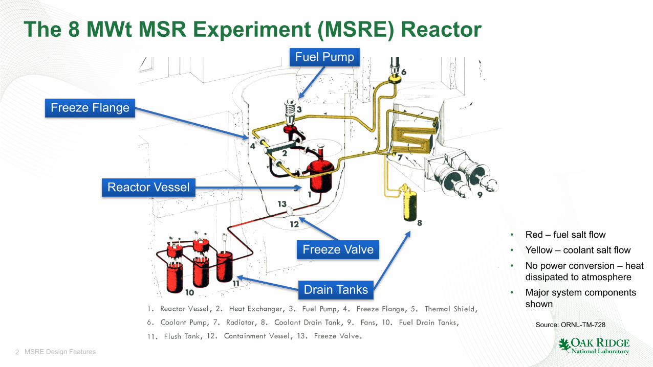
The 8 MWt MSR Experiment (MSRE) Reactor
Source: ORNL-TM-728
• Red – fuel salt flow• Yellow – coolant salt flow• No power conversion – heat
dissipated to atmosphere• Major system components
shownDrain Tanks
Reactor Vessel
Freeze Flange
Fuel Pump
Freeze Valve
3 MSRE Design Features
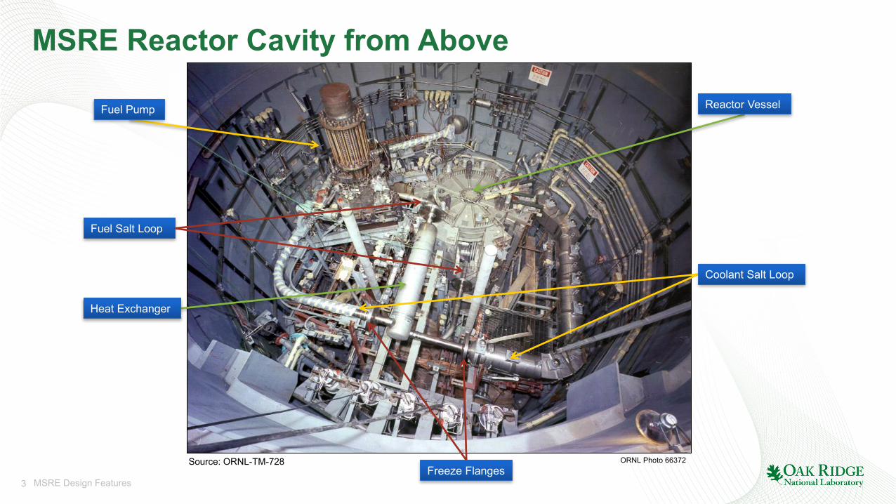
MSRE Reactor Cavity from Above
Source: ORNL-TM-728 ORNL Photo 66372
Fuel Pump Reactor Vessel
Heat Exchanger
Coolant Salt Loop
Fuel Salt Loop
Freeze Flanges
4 MSRE Design Features
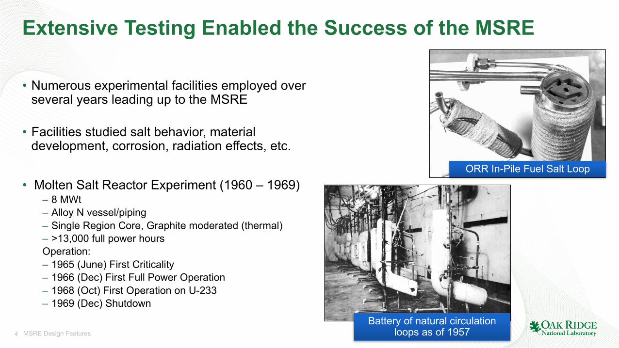
Extensive Testing Enabled the Success of the MSRE
• Numerous experimental facilities employed over several years leading up to the MSRE
• Facilities studied salt behavior, material development, corrosion, radiation effects, etc.
• Molten Salt Reactor Experiment (1960 – 1969)– 8 MWt– Alloy N vessel/piping– Single Region Core, Graphite moderated (thermal)– >13,000 full power hoursOperation:– 1965 (June) First Criticality– 1966 (Dec) First Full Power Operation– 1968 (Oct) First Operation on U-233– 1969 (Dec) Shutdown
Battery of natural circulation loops as of 1957
ORR In-Pile Fuel Salt Loop
5 MSRE Design Features
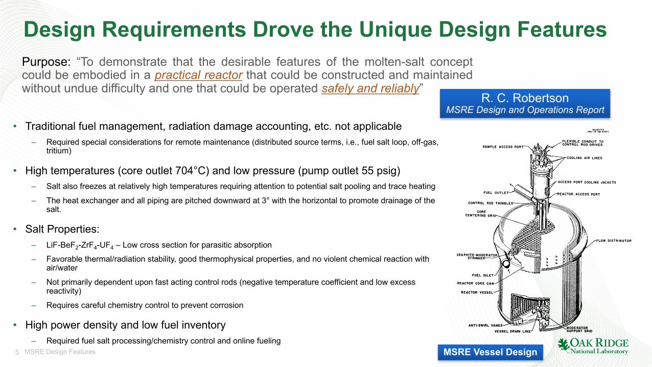
Design Requirements Drove the Unique Design Features
• Traditional fuel management, radiation damage accounting, etc. not applicable– Required special considerations for remote maintenance (distributed source terms, i.e., fuel salt loop, off-gas,
tritium)
• High temperatures (core outlet 704°C) and low pressure (pump outlet 55 psig)– Salt also freezes at relatively high temperatures requiring attention to potential salt pooling and trace heating
– The heat exchanger and all piping are pitched downward at 3° with the horizontal to promote drainage of the salt.
• Salt Properties:– LiF-BeF2-ZrF4-UF4 – Low cross section for parasitic absorption
– Favorable thermal/radiation stability, good thermophysical properties, and no violent chemical reaction with air/water
– Not primarily dependent upon fast acting control rods (negative temperature coefficient and low excess reactivity)
– Requires careful chemistry control to prevent corrosion
• High power density and low fuel inventory– Required fuel salt processing/chemistry control and online fueling
Purpose: “To demonstrate that the desirable features of the molten-salt conceptcould be embodied in a practical reactor that could be constructed and maintainedwithout undue difficulty and one that could be operated safely and reliably”
R. C. RobertsonMSRE Design and Operations Report
MSRE Vessel Design
6 MSRE Design Features
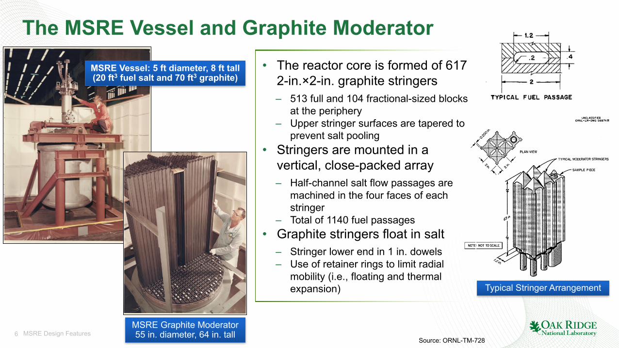
The MSRE Vessel and Graphite Moderator
MSRE Graphite Moderator55 in. diameter, 64 in. tall
Typical Stringer Arrangement
• The reactor core is formed of 617 2-in.×2-in. graphite stringers– 513 full and 104 fractional-sized blocks
at the periphery– Upper stringer surfaces are tapered to
prevent salt pooling• Stringers are mounted in a
vertical, close-packed array– Half-channel salt flow passages are
machined in the four faces of each stringer
– Total of 1140 fuel passages• Graphite stringers float in salt
– Stringer lower end in 1 in. dowels– Use of retainer rings to limit radial
mobility (i.e., floating and thermal expansion)
Source: ORNL-TM-728
MSRE Vessel: 5 ft diameter, 8 ft tall(20 ft3 fuel salt and 70 ft3 graphite)
7 MSRE Design Features
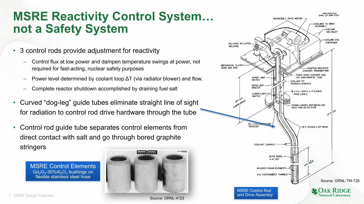
MSRE Reactivity Control System… not a Safety System• 3 control rods provide adjustment for reactivity
– Control flux at low power and dampen temperature swings at power, not required for fast-acting, nuclear safety purposes
– Power level determined by coolant loop ΔT (via radiator blower) and flow.
– Complete reactor shutdown accomplished by draining fuel salt
• Curved “dog-leg” guide tubes eliminate straight line of sight for radiation to control rod drive hardware through the tube
• Control rod guide tube separates control elements from direct contact with salt and go through bored graphite stringers
MSRE Control Rod and Drive Assembly
Source: ORNL-4123
Source: ORNL-TM-728
MSRE Control ElementsGd2O3-30%Al2O3 bushings on
flexible stainless steel hose
8 MSRE Design Features
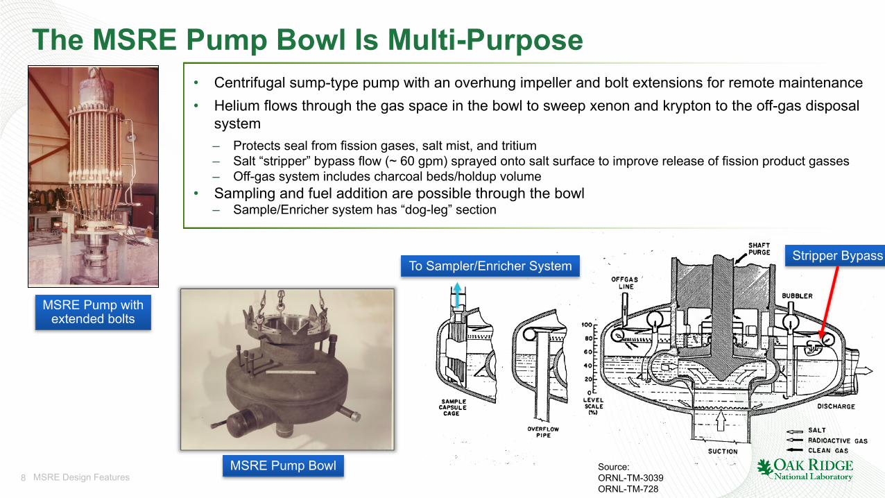
The MSRE Pump Bowl Is Multi-Purpose
Source: ORNL-TM-3039ORNL-TM-728
Stripper BypassTo Sampler/Enricher System
MSRE Pump Bowl
• Centrifugal sump-type pump with an overhung impeller and bolt extensions for remote maintenance• Helium flows through the gas space in the bowl to sweep xenon and krypton to the off-gas disposal
system– Protects seal from fission gases, salt mist, and tritium– Salt “stripper” bypass flow (~ 60 gpm) sprayed onto salt surface to improve release of fission product gasses– Off-gas system includes charcoal beds/holdup volume
• Sampling and fuel addition are possible through the bowl– Sample/Enricher system has “dog-leg” section
MSRE Pump withextended bolts
9 MSRE Design Features
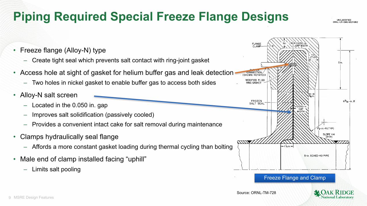
Piping Required Special Freeze Flange Designs
• Freeze flange (Alloy-N) type– Create tight seal which prevents salt contact with ring-joint gasket
• Access hole at sight of gasket for helium buffer gas and leak detection– Two holes in nickel gasket to enable buffer gas to access both sides
• Alloy-N salt screen– Located in the 0.050 in. gap– Improves salt solidification (passively cooled)– Provides a convenient intact cake for salt removal during maintenance
• Clamps hydraulically seal flange– Affords a more constant gasket loading during thermal cycling than bolting
• Male end of clamp installed facing “uphill”– Limits salt pooling
Source: ORNL-TM-728
Freeze Flange and Clamp
10 MSRE Design Features
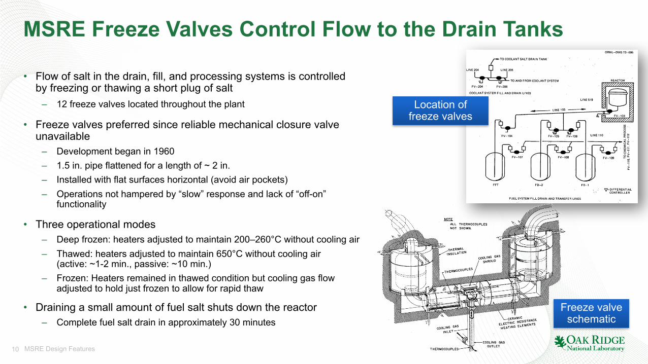
MSRE Freeze Valves Control Flow to the Drain Tanks
• Flow of salt in the drain, fill, and processing systems is controlled by freezing or thawing a short plug of salt
– 12 freeze valves located throughout the plant
• Freeze valves preferred since reliable mechanical closure valve unavailable
– Development began in 1960– 1.5 in. pipe flattened for a length of ~ 2 in.– Installed with flat surfaces horizontal (avoid air pockets)– Operations not hampered by “slow” response and lack of “off-on”
functionality
• Three operational modes– Deep frozen: heaters adjusted to maintain 200–260°C without cooling air– Thawed: heaters adjusted to maintain 650°C without cooling air
(active: ~1-2 min., passive: ~10 min.)– Frozen: Heaters remained in thawed condition but cooling gas flow
adjusted to hold just frozen to allow for rapid thaw
• Draining a small amount of fuel salt shuts down the reactor– Complete fuel salt drain in approximately 30 minutes
Location of freeze valves
Freeze valve schematic
Source: ORNL-TM-3039
11 MSRE Design Features
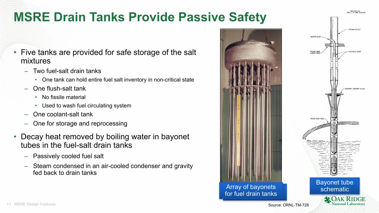
MSRE Drain Tanks Provide Passive Safety
• Five tanks are provided for safe storage of the salt mixtures
– Two fuel-salt drain tanks• One tank can hold entire fuel salt inventory in non-critical state
– One flush-salt tank• No fissile material• Used to wash fuel circulating system
– One coolant-salt tank– One for storage and reprocessing
• Decay heat removed by boiling water in bayonet tubes in the fuel-salt drain tanks
– Passively cooled fuel salt– Steam condensed in an air-cooled condenser and gravity
fed back to drain tanks
Source: ORNL-TM-728
Array of bayonets for fuel drain tanks
Array of bayonets for fuel drain tanks
Bayonet tube schematic
12 MSRE Design Features
A Few Takeaways…
The MSRE…• … was an all-encompassing, mature research project with extensive testing and
documentation• … successfully demonstrated numerous technologies and techniques for high-
temperature molten salt applications– The topics covered in this presentation only scratch the surface of the various design features
and facilities that went into the MSRE
• … technologies are foundational to modern MSR designs• … demonstrated that MSRs are indeed practical to be constructed and able to be
operated safely and reliably
Thank you