msp430fr4133 launchpad™ development kit (msp … · 2018-12-21 · msp430fr4133 launchpad. more...
TRANSCRIPT
1SLAU595B–October 2014–Revised January 2017Submit Documentation Feedback
Copyright © 2014–2017, Texas Instruments Incorporated
MSP430FR4133 LaunchPad™ Development Kit (MSP‑EXP430FR4133)
User's GuideSLAU595B–October 2014–Revised January 2017
MSP430FR4133 LaunchPad™ Development Kit(MSP‑‑EXP430FR4133)
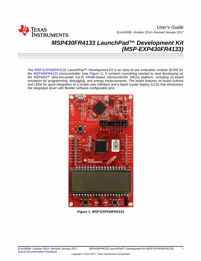
The MSP-EXP430FR4133 LaunchPad™ Development Kit is an easy-to-use evaluation module (EVM) forthe MSP430FR4133 microcontroller (see Figure 1). It contains everything needed to start developing onthe MSP430™ ultra-low-power (ULP) FRAM-based microcontroller (MCU) platform, including on-boardemulation for programming, debugging, and energy measurements. The board features on-board buttonsand LEDs for quick integration of a simple user interface and a liquid crystal display (LCD) that showcasesthe integrated driver with flexible software-configurable pins.
Figure 1. MSP-EXP430FR4133
www.ti.com
2 SLAU595B–October 2014–Revised January 2017Submit Documentation Feedback
Copyright © 2014–2017, Texas Instruments Incorporated
MSP430FR4133 LaunchPad™ Development Kit (MSP‑EXP430FR4133)
Contents1 Getting Started ............................................................................................................... 32 Hardware...................................................................................................................... 53 Software Examples ........................................................................................................ 174 Additional Resources ...................................................................................................... 225 FAQ .......................................................................................................................... 246 Schematics.................................................................................................................. 25
List of Figures
1 MSP-EXP430FR4133 ....................................................................................................... 12 MSP-EXP430FR4133 Overview ........................................................................................... 53 Block Diagram................................................................................................................ 64 MSP430FR4133 Pinout..................................................................................................... 75 eZ-FET Emulator ............................................................................................................ 86 eZ-FET Isolation Jumper Block Diagram ............................................................................... 107 Application Backchannel UART in Device Manager................................................................... 108 LCD Segment Layout...................................................................................................... 119 MSP-EXP430FR4133 Power Block Diagram........................................................................... 1410 LaunchPad to BoosterPack Connector Pinout ......................................................................... 1611 Programming the LaunchPad With Program Batch Files ............................................................. 1812 Directing the Project>Import Function to the Demo Project .......................................................... 1913 When CCS Has Found the Project ...................................................................................... 2014 MSP-EXP430FR4133 Software Examples in TI Resource Explorer ................................................ 2315 Schematics (1 of 6) ........................................................................................................ 2516 Schematics (2 of 6) ........................................................................................................ 2617 Schematics (3 of 6) ........................................................................................................ 2718 Schematics (4 of 6) ........................................................................................................ 2819 Schematics (5 of 6) ........................................................................................................ 2920 Schematics (6 of 6) ........................................................................................................ 30
List of Tables
1 EnergyTrace Technology ................................................................................................... 82 Isolation Block Connections ................................................................................................ 93 LCD FH-1138P Segment Mapping ...................................................................................... 124 LCD to MSP430 Connections ............................................................................................ 135 Hardware Change Log .................................................................................................... 176 Software Examples ........................................................................................................ 177 IDE Minimum Requirements for MSP-EXP430FR4133 ............................................................... 188 List of Source Files and Folders ......................................................................................... 219 How MSP430 Device Documentation is Organized ................................................................... 22
www.ti.com Getting Started
3SLAU595B–October 2014–Revised January 2017Submit Documentation Feedback
Copyright © 2014–2017, Texas Instruments Incorporated
MSP430FR4133 LaunchPad™ Development Kit (MSP‑EXP430FR4133)
TrademarksLaunchPad, MSP430, BoosterPack, Code Composer Studio, EnergyTrace, E2E are trademarks of TexasInstruments.IAR Embedded Workbench is a registered trademark of IAR Systems.
1 Getting Started
1.1 IntroductionThe MSP-EXP430FR4133 LaunchPad™ Development Kit is an easy-to-use Evaluation Module (EVM) forthe MSP430FR4133 microcontroller (see Figure 1). It contains everything needed to start developing onthe MSP430™ ultra-low-power (ULP) FRAM-based microcontroller (MCU) platform, including on-boardemulation for programming, debugging, and energy measurements. The board features on-board buttonsand LEDs for quick integration of a simple user interface and a liquid crystal display (LCD) that showcasesthe integrated driver with flexible software-configurable pins. The MSP430FR4133 device featuresembedded FRAM (ferroelectric random access memory), a nonvolatile memory known for its ultra-lowpower, high endurance, and high-speed write access.
Rapid prototyping is simplified by the 20-pin BoosterPack™ Plug-in Module headers, which support a widerange of available BoosterPacks. You can quickly add features like wireless connectivity, graphicaldisplays, environmental sensing, and much more. Design your own BoosterPack or choose among manyalready available from TI and third-party developers.
Free software development tools are also available, including TI's Eclipse-based Code ComposerStudio™ (CCSTUDIO) and IAR Embedded Workbench® IAR-KICKSTART. Both of these integrateddevelopment environments (IDEs) support EnergyTrace™ technology when paired with theMSP430FR4133 LaunchPad. More information about the LaunchPad, the supported BoosterPacks, andavailable resources can be found at TI's LaunchPad portal.
1.2 Key Features• MSP430 ultra-low-power FRAM technology based MSP430FR4133 16-bit MCU• 20-pin LaunchPad standard that leverages the BoosterPack ecosystem• eZ-FET, an open-source onboard debugger that features EnergyTrace technology• On-board segmented LCD• Two buttons and two LEDs for user interaction• Backchannel UART through USB to PC
1.3 What's Included
1.3.1 Kit Contents• 1 x MSP-EXP430FR4133 LaunchPad Development Kit• 1 x micro-USB cable• 1 x Quick Start Guide
1.3.2 Software Examples• Out-of-Box Software
1.4 First Steps: Out-of-Box ExperienceAn easy way to get familiar with the EVM is by using its preprogrammed out-of-box code. It demonstratessome key features from a user level.
Getting Started www.ti.com
4 SLAU595B–October 2014–Revised January 2017Submit Documentation Feedback
Copyright © 2014–2017, Texas Instruments Incorporated
MSP430FR4133 LaunchPad™ Development Kit (MSP‑EXP430FR4133)
1.4.1 Connecting to the ComputerConnect the LaunchPad using the included USB cable to a computer. A green power LED shouldilluminate. For proper operation, drivers are needed. It is recommended to get drivers by installing an IDEsuch as TI's CCS or IAR EW430. Drivers are also available at www.ti.com/MSPdrivers.
1.4.2 Running the Out-of-Box DemoWhen connected to the computer, the LaunchPad powers up and displays a greeting message on theLCD. Press and hold the S1 and S2 buttons simultaneously to select a new mode. A more detailedexplanation of each mode can be found in Section 3.4.
1.4.2.1 Stopwatch ModeThis mode provides a simple stopwatch application. It supports split time, where the display freezes whilethe stopwatch continues running in the background.
Timer Stopped:S1: Start timeS2: Reset time
Timer Running:S1: Stop timeS2: Split time (lap time)
1.4.2.2 Temperature ModeThis mode provides a simple thermometer application. Using the on-chip temperature sensor, thetemperature is displayed on the LCD.
S1: Pause current temperatureS2: Toggle temperature between °F and °C
1.5 Next Steps: Looking Into the Provided CodeAfter the EVM features have been explored, the fun can begin. It's time to open an integrateddevelopment environment and start editing the code examples. Refer to Section 3.3 for more informationon IDEs and where to download them.
The out-of-box source code and more code examples are provided for download athttp://www.ti.com/tool/msp-exp430fr4133. Code is licensed under BSD, and TI encourages reuse andmodifications to fit specific needs.
Section 3 describes all of the functions in detail and describes the project structure to help familiarize youwith the code.
With the onboard eZ-FET emulator debugging and downloading new code is simple. A USB connectionbetween the EVM and a PC through the provided USB cable is all that is needed.
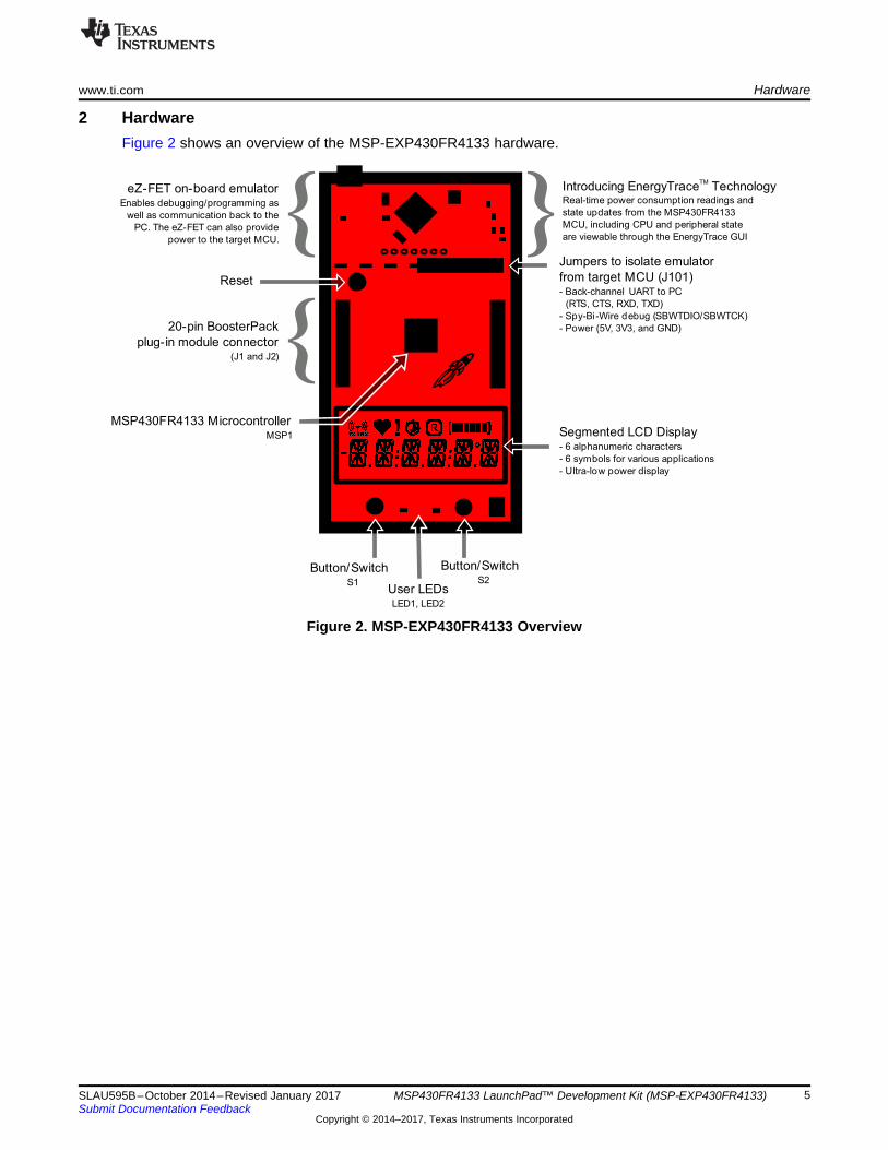
{eZ-FET on-board emulator
Enables debugging/programming as
well as communication back to the
PC. The eZ-FET can also provide
power to the target MCU.
Introducing EnergyTrace TechnologyTM
Real-time power consumption readings and
state updates from the MSP430FR4133
MCU, including CPU and peripheral state
are viewable through the EnergyTrace GUI
Jumpers to isolate emulator
from target MCU (J101)- Back-channel UART to PC
(RTS, CTS, RXD, TXD)
- Spy-Bi-Wire debug (SBWTDIO/SBWTCK)
- Power (5V, 3V3, and GND)20-pin BoosterPack
plug-in module connector(J1 and J2){
Button/SwitchS2
User LEDsLED1, LED2
Button/SwitchS1
Segmented LCD Display- 6 alphanumeric characters
- 6 symbols for various applications
- Ultra-low power display
MSP430FR4133 MicrocontrollerMSP1
Reset
{
www.ti.com Hardware
5SLAU595B–October 2014–Revised January 2017Submit Documentation Feedback
Copyright © 2014–2017, Texas Instruments Incorporated
MSP430FR4133 LaunchPad™ Development Kit (MSP‑EXP430FR4133)
2 HardwareFigure 2 shows an overview of the MSP-EXP430FR4133 hardware.
Figure 2. MSP-EXP430FR4133 Overview
Target Device
MSP430FR4133
Crystal
32.768 kHz
Micro-B
USB
3.3-VLDO
ESD
Protection
Debug
MCU
LEDs
Red, GreenCrystal
4 MHz
UART/SBW to Target
User Interface
2 Buttons and 2 LEDs
20-pin LaunchPad
standard headers
Power to Target
Reset
button Segmented LCD
EnergyTrace
Hardware www.ti.com
6 SLAU595B–October 2014–Revised January 2017Submit Documentation Feedback
Copyright © 2014–2017, Texas Instruments Incorporated
MSP430FR4133 LaunchPad™ Development Kit (MSP‑EXP430FR4133)
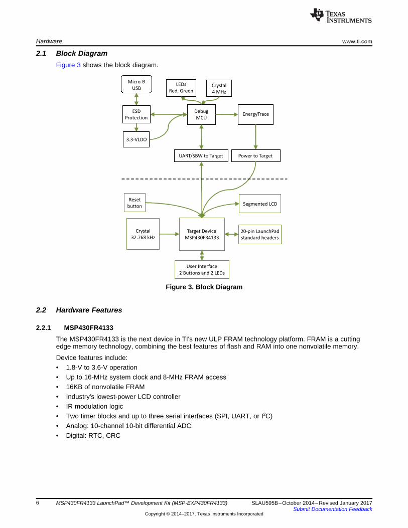
2.1 Block DiagramFigure 3 shows the block diagram.
Figure 3. Block Diagram
2.2 Hardware Features
2.2.1 MSP430FR4133The MSP430FR4133 is the next device in TI's new ULP FRAM technology platform. FRAM is a cuttingedge memory technology, combining the best features of flash and RAM into one nonvolatile memory.
Device features include:• 1.8-V to 3.6-V operation• Up to 16-MHz system clock and 8-MHz FRAM access• 16KB of nonvolatile FRAM• Industry's lowest-power LCD controller• IR modulation logic• Two timer blocks and up to three serial interfaces (SPI, UART, or I2C)• Analog: 10-channel 10-bit differential ADC• Digital: RTC, CRC
P4.7/R13
P4.6/R23
P4.5/R33
P4.4/LCDCAP1
P4.3/LCDCAP0
P4.2/XOUT
P4.1/XIN
DVSS
DVCC
RST/NMI/SBWTDIO
TEST/SBWTCK
P4.0/TA1.1
P8.3/TA1.2
P8.2/TA1CLK
P8.1/ACLK/A9
P8.0/SMCLK/A8
P1.7
/TA
0.1
/TD
O/A
7
P1.6
/TA
0.2
/TD
I/T
CLK
/A6
P1.5
/TA
0C
LK
/TM
S/A
5
P1.4
/MC
LK
/TC
K/A
4/V
RE
F+
P1.3
/UC
A0S
TE
/A3
P1.2
/UC
A0C
LK
/A2
P1.1
//A
1/
UC
A0R
XD
/UC
A0S
OM
IV
ere
f+
P1.0
//A
0/V
ere
f–U
CA
0T
XD
/UC
A0S
IMO
P5.7
/L39
P5.6
/L38
P5.5
/L37
P5.4
/L36
P5.3
/UC
B0S
OM
I/U
CB
0S
CL/L
35
P5.2
/UC
B0S
IMO
/UC
B0S
DA
/L34
P5.1
/UC
B0C
LK
/L33
P5.0
/UC
B0S
TE
/L32
P2.7/L31
P2.6/L30
P2.5/L29
P2.4/L28
P2.3/L27
P2.2/L26
P2.1/L25
P2.0/L24
P6.7/L23
P6.6/L22
P6.5/L21
P6.4/L20
P6.3/L19
P6.2/L18
P6.1/L17
P6.0/L16
P3.7
/L15
P3.6
/L14
P3.5
/L13
P3.4
/L12
P3.3
/L11
P3.2
/L10
P3.1
/L9
P3.0
/L8
P7.7
/L7
P7.6
/L6
P7.5
/L5
P7.4
/L4
P7.3
/L3
P7.2
/L2
P7.1
/L1
P7.0
/L0
1
2
3
4
5
6
7
8
9
10
11
12
13
14
15
16
17
18
19
20
21
22
23
24
25
26
27
28
29
30
31
32
33
34
35
36
37
38
39
40
41
42
43
44
45
46
47
48
49
50
51
52
53
54
55
56
57
58
59
60
61
62
63
64
www.ti.com Hardware
7SLAU595B–October 2014–Revised January 2017Submit Documentation Feedback
Copyright © 2014–2017, Texas Instruments Incorporated
MSP430FR4133 LaunchPad™ Development Kit (MSP‑EXP430FR4133)
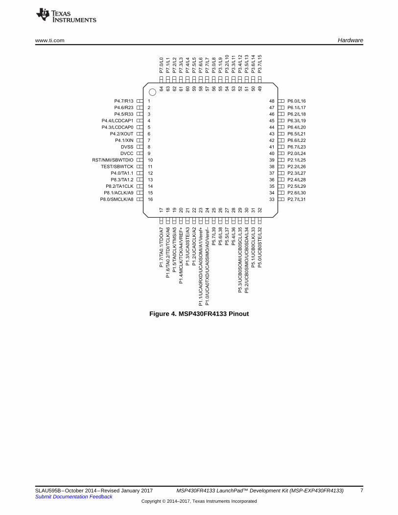
Figure 4. MSP430FR4133 Pinout
Hardware www.ti.com
8 SLAU595B–October 2014–Revised January 2017Submit Documentation Feedback
Copyright © 2014–2017, Texas Instruments Incorporated
MSP430FR4133 LaunchPad™ Development Kit (MSP‑EXP430FR4133)
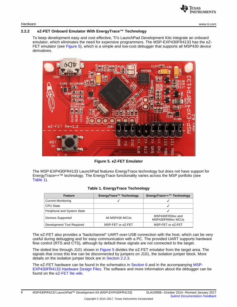
2.2.2 eZ-FET Onboard Emulator With EnergyTrace™ TechnologyTo keep development easy and cost effective, TI's LaunchPad Development Kits integrate an onboardemulator, which eliminates the need for expensive programmers. The MSP-EXP430FR4133 has the eZ-FET emulator (see Figure 5), which is a simple and low-cost debugger that supports all MSP430 devicederivatives.
Figure 5. eZ-FET Emulator
The MSP-EXP430FR4133 LaunchPad features EnergyTrace technology but does not have support forEnergyTrace++™ technology. The EnergyTrace functionality varies across the MSP portfolio (seeTable 1).
Table 1. EnergyTrace Technology
Feature EnergyTrace™ Technology EnergyTrace++™ TechnologyCurrent Monitoring ✓ ✓CPU State ✓Peripheral and System State ✓
Devices Supported All MSP430 MCUs MSP430FR59xx andMSP430FR69xx MCUs
Development Tool Required MSP-FET or eZ-FET MSP-FET or eZ-FET
The eZ-FET also provides a "backchannel" UART-over-USB connection with the host, which can be veryuseful during debugging and for easy communication with a PC. The provided UART supports hardwareflow control (RTS and CTS), although by default these signals are not connected to the target.
The dotted line through J101 shown in Figure 5 divides the eZ-FET emulator from the target area. Thesignals that cross this line can be disconnected by jumpers on J101, the isolation jumper block. Moredetails on the isolation jumper block are in Section 2.2.3.
The eZ-FET hardware can be found in the schematics in Section 6 and in the accompanying MSP-EXP430FR4133 Hardware Design Files. The software and more information about the debugger can befound on the eZ-FET lite wiki.
www.ti.com Hardware
9SLAU595B–October 2014–Revised January 2017Submit Documentation Feedback
Copyright © 2014–2017, Texas Instruments Incorporated
MSP430FR4133 LaunchPad™ Development Kit (MSP‑EXP430FR4133)
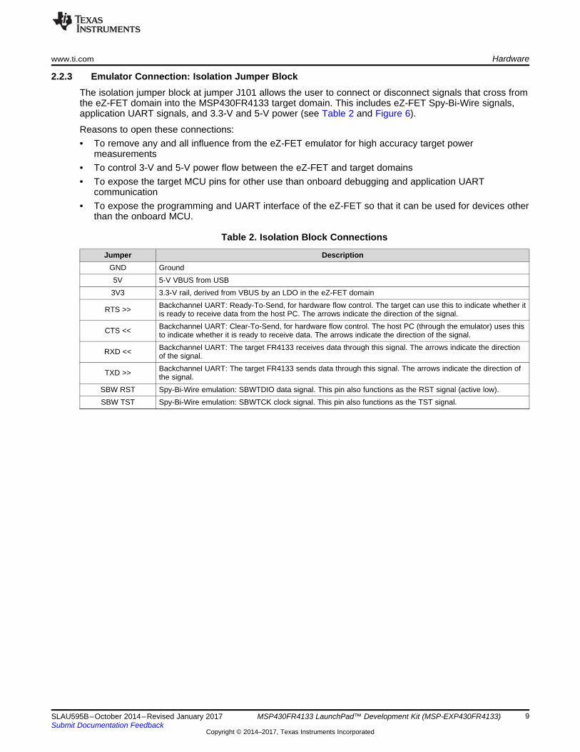
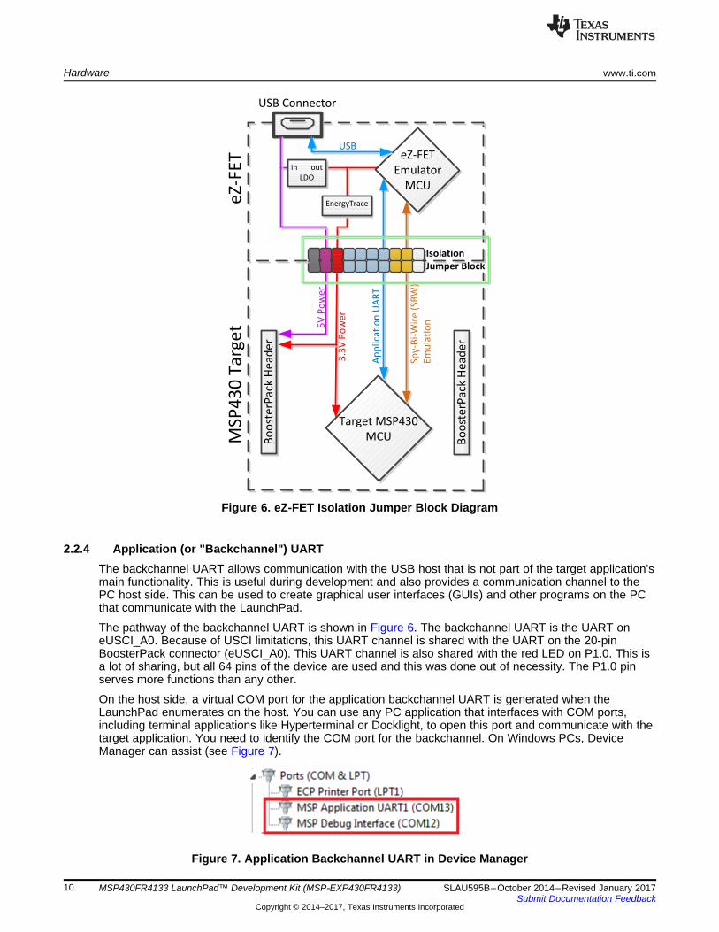
2.2.3 Emulator Connection: Isolation Jumper BlockThe isolation jumper block at jumper J101 allows the user to connect or disconnect signals that cross fromthe eZ-FET domain into the MSP430FR4133 target domain. This includes eZ-FET Spy-Bi-Wire signals,application UART signals, and 3.3-V and 5-V power (see Table 2 and Figure 6).
Reasons to open these connections:• To remove any and all influence from the eZ-FET emulator for high accuracy target power
measurements• To control 3-V and 5-V power flow between the eZ-FET and target domains• To expose the target MCU pins for other use than onboard debugging and application UART
communication• To expose the programming and UART interface of the eZ-FET so that it can be used for devices other
than the onboard MCU.
Table 2. Isolation Block Connections
Jumper DescriptionGND Ground5V 5-V VBUS from USB3V3 3.3-V rail, derived from VBUS by an LDO in the eZ-FET domain
RTS >> Backchannel UART: Ready-To-Send, for hardware flow control. The target can use this to indicate whether itis ready to receive data from the host PC. The arrows indicate the direction of the signal.
CTS << Backchannel UART: Clear-To-Send, for hardware flow control. The host PC (through the emulator) uses thisto indicate whether it is ready to receive data. The arrows indicate the direction of the signal.
RXD << Backchannel UART: The target FR4133 receives data through this signal. The arrows indicate the directionof the signal.
TXD >> Backchannel UART: The target FR4133 sends data through this signal. The arrows indicate the direction ofthe signal.
SBW RST Spy-Bi-Wire emulation: SBWTDIO data signal. This pin also functions as the RST signal (active low).SBW TST Spy-Bi-Wire emulation: SBWTCK clock signal. This pin also functions as the TST signal.
eZ-FET
Emulator
MCU
Isolation
Jumper Block
Sp
y-B
i-W
ire
(S
BW
)
Em
ula
tio
n
Ap
pli
cati
on
UA
RT
3.3
V P
ow
er
5V
Po
we
r
Target MSP430
MCU
eZ
-FE
TM
SP
43
0 T
arg
et
USB Connector
in out
LDO
Bo
ost
erP
ack
He
ad
er
Bo
ost
erP
ack
He
ad
er
USB
EnergyTrace
Hardware www.ti.com
10 SLAU595B–October 2014–Revised January 2017Submit Documentation Feedback
Copyright © 2014–2017, Texas Instruments Incorporated
MSP430FR4133 LaunchPad™ Development Kit (MSP‑EXP430FR4133)
Figure 6. eZ-FET Isolation Jumper Block Diagram
2.2.4 Application (or "Backchannel") UARTThe backchannel UART allows communication with the USB host that is not part of the target application'smain functionality. This is useful during development and also provides a communication channel to thePC host side. This can be used to create graphical user interfaces (GUIs) and other programs on the PCthat communicate with the LaunchPad.
The pathway of the backchannel UART is shown in Figure 6. The backchannel UART is the UART oneUSCI_A0. Because of USCI limitations, this UART channel is shared with the UART on the 20-pinBoosterPack connector (eUSCI_A0). This UART channel is also shared with the red LED on P1.0. This isa lot of sharing, but all 64 pins of the device are used and this was done out of necessity. The P1.0 pinserves more functions than any other.
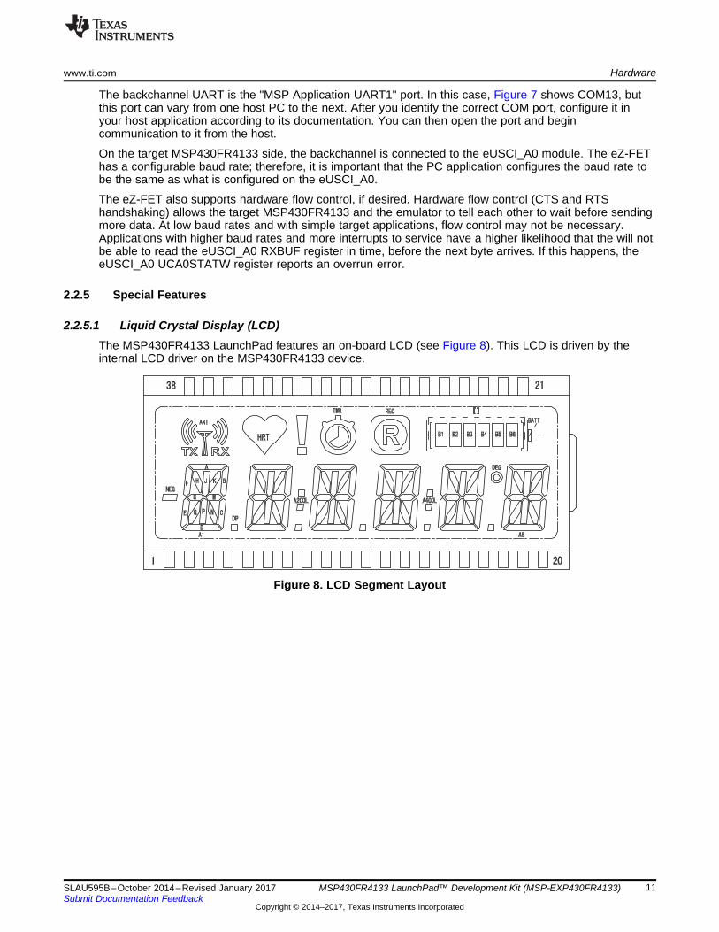
On the host side, a virtual COM port for the application backchannel UART is generated when theLaunchPad enumerates on the host. You can use any PC application that interfaces with COM ports,including terminal applications like Hyperterminal or Docklight, to open this port and communicate with thetarget application. You need to identify the COM port for the backchannel. On Windows PCs, DeviceManager can assist (see Figure 7).
Figure 7. Application Backchannel UART in Device Manager
www.ti.com Hardware
11SLAU595B–October 2014–Revised January 2017Submit Documentation Feedback
Copyright © 2014–2017, Texas Instruments Incorporated
MSP430FR4133 LaunchPad™ Development Kit (MSP‑EXP430FR4133)
The backchannel UART is the "MSP Application UART1" port. In this case, Figure 7 shows COM13, butthis port can vary from one host PC to the next. After you identify the correct COM port, configure it inyour host application according to its documentation. You can then open the port and begincommunication to it from the host.
On the target MSP430FR4133 side, the backchannel is connected to the eUSCI_A0 module. The eZ-FEThas a configurable baud rate; therefore, it is important that the PC application configures the baud rate tobe the same as what is configured on the eUSCI_A0.
The eZ-FET also supports hardware flow control, if desired. Hardware flow control (CTS and RTShandshaking) allows the target MSP430FR4133 and the emulator to tell each other to wait before sendingmore data. At low baud rates and with simple target applications, flow control may not be necessary.Applications with higher baud rates and more interrupts to service have a higher likelihood that the will notbe able to read the eUSCI_A0 RXBUF register in time, before the next byte arrives. If this happens, theeUSCI_A0 UCA0STATW register reports an overrun error.
2.2.5 Special Features
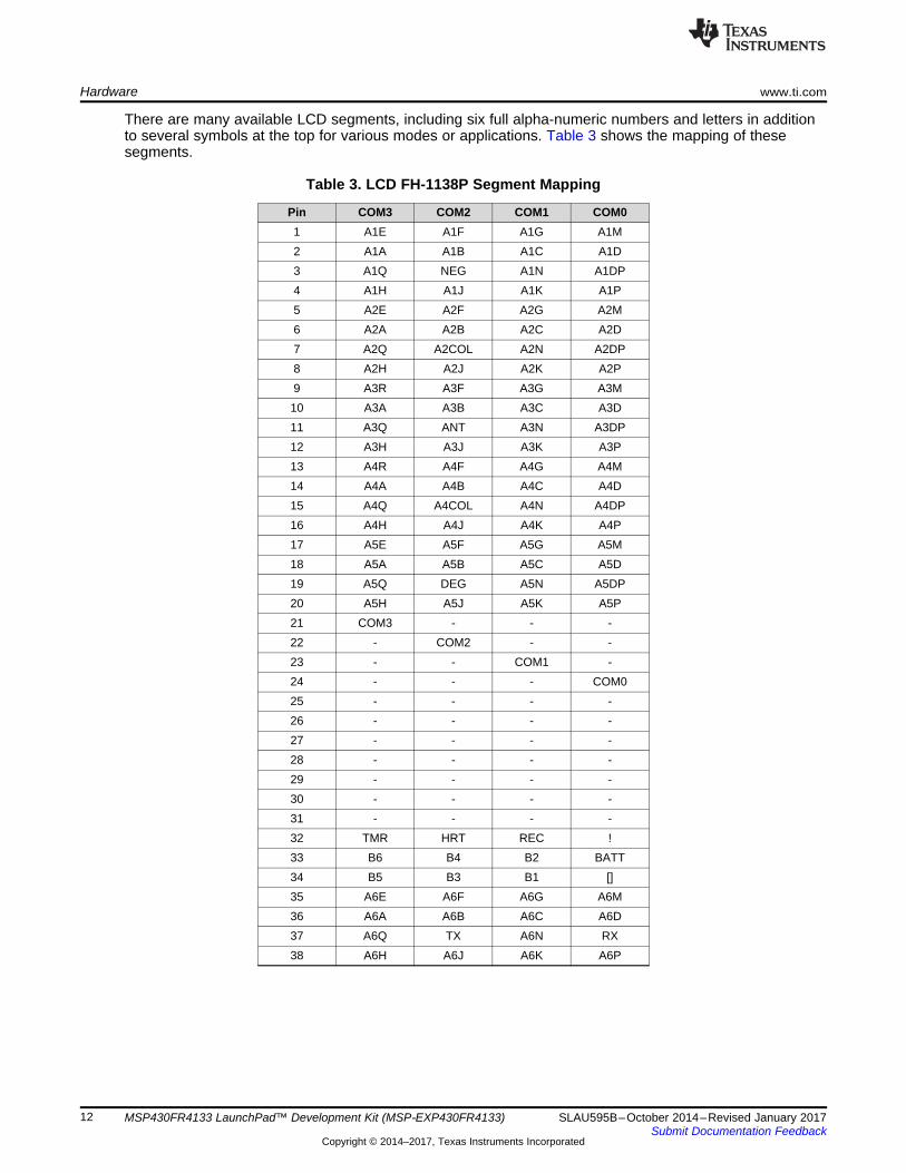
2.2.5.1 Liquid Crystal Display (LCD)The MSP430FR4133 LaunchPad features an on-board LCD (see Figure 8). This LCD is driven by theinternal LCD driver on the MSP430FR4133 device.
Figure 8. LCD Segment Layout
Hardware www.ti.com
12 SLAU595B–October 2014–Revised January 2017Submit Documentation Feedback
Copyright © 2014–2017, Texas Instruments Incorporated
MSP430FR4133 LaunchPad™ Development Kit (MSP‑EXP430FR4133)
There are many available LCD segments, including six full alpha-numeric numbers and letters in additionto several symbols at the top for various modes or applications. Table 3 shows the mapping of thesesegments.
Table 3. LCD FH-1138P Segment Mapping
Pin COM3 COM2 COM1 COM01 A1E A1F A1G A1M2 A1A A1B A1C A1D3 A1Q NEG A1N A1DP4 A1H A1J A1K A1P5 A2E A2F A2G A2M6 A2A A2B A2C A2D7 A2Q A2COL A2N A2DP8 A2H A2J A2K A2P9 A3R A3F A3G A3M10 A3A A3B A3C A3D11 A3Q ANT A3N A3DP12 A3H A3J A3K A3P13 A4R A4F A4G A4M14 A4A A4B A4C A4D15 A4Q A4COL A4N A4DP16 A4H A4J A4K A4P17 A5E A5F A5G A5M18 A5A A5B A5C A5D19 A5Q DEG A5N A5DP20 A5H A5J A5K A5P21 COM3 - - -22 - COM2 - -23 - - COM1 -24 - - - COM025 - - - -26 - - - -27 - - - -28 - - - -29 - - - -30 - - - -31 - - - -32 TMR HRT REC !33 B6 B4 B2 BATT34 B5 B3 B1 []35 A6E A6F A6G A6M36 A6A A6B A6C A6D37 A6Q TX A6N RX38 A6H A6J A6K A6P
www.ti.com Hardware
13SLAU595B–October 2014–Revised January 2017Submit Documentation Feedback
Copyright © 2014–2017, Texas Instruments Incorporated
MSP430FR4133 LaunchPad™ Development Kit (MSP‑EXP430FR4133)
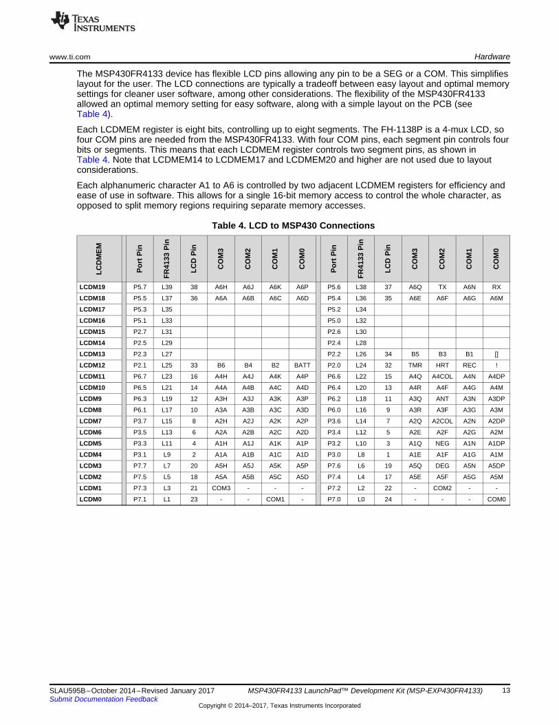
The MSP430FR4133 device has flexible LCD pins allowing any pin to be a SEG or a COM. This simplifieslayout for the user. The LCD connections are typically a tradeoff between easy layout and optimal memorysettings for cleaner user software, among other considerations. The flexibility of the MSP430FR4133allowed an optimal memory setting for easy software, along with a simple layout on the PCB (seeTable 4).
Each LCDMEM register is eight bits, controlling up to eight segments. The FH-1138P is a 4-mux LCD, sofour COM pins are needed from the MSP430FR4133. With four COM pins, each segment pin controls fourbits or segments. This means that each LCDMEM register controls two segment pins, as shown inTable 4. Note that LCDMEM14 to LCDMEM17 and LCDMEM20 and higher are not used due to layoutconsiderations.
Each alphanumeric character A1 to A6 is controlled by two adjacent LCDMEM registers for efficiency andease of use in software. This allows for a single 16-bit memory access to control the whole character, asopposed to split memory regions requiring separate memory accesses.
Table 4. LCD to MSP430 Connections
LCD
MEM
Port
Pin
FR41
33Pi
n
LCD
Pin
CO
M3
CO
M2
CO
M1
CO
M0
Port
Pin
FR41
33Pi
n
LCD
Pin
CO
M3
CO
M2
CO
M1
CO
M0
LCDM19 P5.7 L39 38 A6H A6J A6K A6P P5.6 L38 37 A6Q TX A6N RX
LCDM18 P5.5 L37 36 A6A A6B A6C A6D P5.4 L36 35 A6E A6F A6G A6M
LCDM17 P5.3 L35 P5.2 L34
LCDM16 P5.1 L33 P5.0 L32
LCDM15 P2.7 L31 P2.6 L30
LCDM14 P2.5 L29 P2.4 L28
LCDM13 P2.3 L27 P2.2 L26 34 B5 B3 B1 []
LCDM12 P2.1 L25 33 B6 B4 B2 BATT P2.0 L24 32 TMR HRT REC !
LCDM11 P6.7 L23 16 A4H A4J A4K A4P P6.6 L22 15 A4Q A4COL A4N A4DP
LCDM10 P6.5 L21 14 A4A A4B A4C A4D P6.4 L20 13 A4R A4F A4G A4M
LCDM9 P6.3 L19 12 A3H A3J A3K A3P P6.2 L18 11 A3Q ANT A3N A3DP
LCDM8 P6.1 L17 10 A3A A3B A3C A3D P6.0 L16 9 A3R A3F A3G A3M
LCDM7 P3.7 L15 8 A2H A2J A2K A2P P3.6 L14 7 A2Q A2COL A2N A2DP
LCDM6 P3.5 L13 6 A2A A2B A2C A2D P3.4 L12 5 A2E A2F A2G A2M
LCDM5 P3.3 L11 4 A1H A1J A1K A1P P3.2 L10 3 A1Q NEG A1N A1DP
LCDM4 P3.1 L9 2 A1A A1B A1C A1D P3.0 L8 1 A1E A1F A1G A1M
LCDM3 P7.7 L7 20 A5H A5J A5K A5P P7.6 L6 19 A5Q DEG A5N A5DP
LCDM2 P7.5 L5 18 A5A A5B A5C A5D P7.4 L4 17 A5E A5F A5G A5M
LCDM1 P7.3 L3 21 COM3 - - - P7.2 L2 22 - COM2 - -
LCDM0 P7.1 L1 23 - - COM1 - P7.0 L0 24 - - - COM0
Debug
Power
Domain
Target and
BoosterPack
Power
Domain
LegendJ101
3V
3
eZ-FET
J1 J2
MSP430FR4133
target and
BoosterPack
VCC
GND
GND
J6
Target
MSP430FR4133
Device
LCD
USB (eZ-FET) Power
Configuration
Pla
ce
Ju
mp
er
BoosterPack and External
Power Configuration
J101
3V
3
eZ-FET
J1 J2
MSP430FR4133
target and
BoosterPack
VCC
GND
GND
J6
Target
MSP430FR4133
Device
LCD
No
Ju
mp
er
Hardware www.ti.com
14 SLAU595B–October 2014–Revised January 2017Submit Documentation Feedback
Copyright © 2014–2017, Texas Instruments Incorporated
MSP430FR4133 LaunchPad™ Development Kit (MSP‑EXP430FR4133)
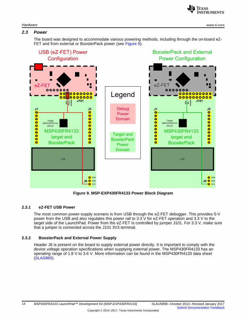
2.3 PowerThe board was designed to accommodate various powering methods, including through the on-board eZ-FET and from external or BoosterPack power (see Figure 9).
Figure 9. MSP-EXP430FR4133 Power Block Diagram
2.3.1 eZ-FET USB PowerThe most common power-supply scenario is from USB through the eZ-FET debugger. This provides 5-Vpower from the USB and also regulates this power rail to 3.3 V for eZ-FET operation and 3.3 V to thetarget side of the LaunchPad. Power from the eZ-FET is controlled by jumper J101. For 3.3 V, make surethat a jumper is connected across the J101 3V3 terminal.
2.3.2 BoosterPack and External Power SupplyHeader J6 is present on the board to supply external power directly. It is important to comply with thedevice voltage operation specifications when supplying external power. The MSP430FR4133 has anoperating range of 1.8 V to 3.6 V. More information can be found in the MSP430FR4133 data sheet(SLAS865).
www.ti.com Hardware
15SLAU595B–October 2014–Revised January 2017Submit Documentation Feedback
Copyright © 2014–2017, Texas Instruments Incorporated
MSP430FR4133 LaunchPad™ Development Kit (MSP‑EXP430FR4133)
2.4 Measure MSP430 Current DrawTo measure the current draw of the MSP430FR4133 using a multi-meter, use the 3V3 jumper on thejumper isolation block. The current measured includes the target device and any current drawn throughthe BoosterPack headers.
To measure ultra-low power, follow these steps:1. Remove the 3V3 jumper in the isolation block, and attach an ammeter across this jumper.2. Consider the effect that the backchannel UART and any circuitry attached to the MSP430FR4133 may
have on current draw. Consider disconnecting these at the isolation jumper block, or at least considertheir current sinking and sourcing capability in the final measurement.
3. Make sure there are no floating input/output (I/Os). These cause unnecessary extra current draw.Every I/O should either be driven out or, if it is an input, should be pulled or driven to a high or lowlevel.
4. Begin target execution.5. Measure the current. Keep in mind that if the current levels are fluctuating, it may be difficult to get a
stable measurement. It is easier to measure quiescent states.
Alternatively, EnergyTrace technology can be used to measure the same current, and see energy profilesthrough integrated GUI in CCS and IAR. EnergyTrace allows you to compare various current profiles andbetter optimize your energy performance!
2.5 ClockingThe MSP-EXP430FR4133 provides an external clock in addition to the internal clocks in the device.• Y1: a 32-kHz crystal
The 32-kHz crystal allows for lower LPM3 sleep currents than do the other low-frequency clock sources.Therefore, the presence of the crystal allows the full range of low-power modes to be used.
The internal clocks in the device default to the following configuration:• MCLK: DCO, 2 MHz• SMCLK: DCO, 2 MHz• ACLK: REFO, 32.768 kHz
For more information about configuring internal clocks and using the external oscillators, see theMSP430FR4xx and MSP430FR2xx Family User's Guide (SLAU445).
2.6 Using the eZ-FET Emulator With a Different TargetThe eZ-FET emulator on the LaunchPad can interface to most MSP430 derivative devices, not just the on-board MSP430FR4133 target device.
To do this, disconnect every jumper in the isolation jumper block. This is necessary, because the emulatorcannot connect to more than one target at a time over the Spy-Bi-Wire (SBW) connection.
Next, make sure the target board has proper connections for SBW. Note that to be compatible with SBW,the capacitor on RST/SBWTDIO cannot be greater than 2.2 nF. The documentation for designing MSP430JTAG interface circuitry is the MSP430 Hardware Tools User's Guide (SLAU278).
Finally, wire together these signals from the emulator side of the isolation jumper block to the targethardware:
• 5 V (if 5 V is needed)• 3.3 V• GND• SBWTDIO• SBWTCK
• TXD (if the UART backchannel is used)• RXD (if the UART backchannel is used)• CTS (if hardware flow control is used)• RTS (if hardware flow control is used)
This wiring can be done either with jumper wires or by designing the board with a connector that plugsinto the isolation jumper block.
The following pins are exposed at the BoosterPack connector.
+3.3V
P8.1
P2.7
P1.1
P8.0
P5.1
P2.5
P8.2
P8.3
P1.0UART
RX
TX
Analog In
Analog In
SPI CLK
I2C*SCL
SDA
A9
A1UCA0RXDUCA0SOMI
A0UCA0TXDUCA0SIMO
L31
SMCLK A8
L33UCB0CLK
L29
TA1CLK
TA1.2
BoosterPack
StandardMSP-EXP430FR4133 Pin Map
+3.3V
GPIO (!)
GPIO (!)
(!)
(!)
(!)
(!)
AC LK
GND
P1.7
P1.6
RST
P5.2
P1.3
P1.4
P1.5
P5.3
A7TA0.1 TDO
L34 UCB0SDA
L35 UCB0SCLUCB0SOMI
A4MCLK TCK
A5TMS TA0CLK
A6TA0.2 TDI TCLK
A3
UCB0STE
UCB0SIMOSPI
MOSI
MISO
SPI CS Wireless
SPI CS Display
SPI CS Other
BoosterPack StandardMSP-EXP430FR4133 Pin Map
GND
RST
PWM Out GPIO (!)
GPIO (!)
GPIO (!)
GPIO (!)
GPIO (!)
(!)
(!)
(!)
(!)
(!)
UCA0STE
P5.0 L32 GPIO**
Also shown are functions that map with the BoosterPack standard.* Note that to comply with the I C channels of the BoosterPack standard, a software-emulated I C must be used.** Some LaunchPads do not 100% comply with the standard, please check your LaunchPad to ensure compatability(!) Denotes I/O pins that are interrupt-capable.
2 2
Hardware www.ti.com
16 SLAU595B–October 2014–Revised January 2017Submit Documentation Feedback
Copyright © 2014–2017, Texas Instruments Incorporated
MSP430FR4133 LaunchPad™ Development Kit (MSP‑EXP430FR4133)
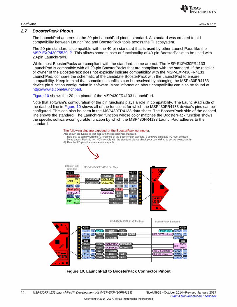
2.7 BoosterPack PinoutThe LaunchPad adheres to the 20-pin LaunchPad pinout standard. A standard was created to aidcompatibility between LaunchPad and BoosterPack tools across the TI ecosystem.
The 20-pin standard is compatible with the 40-pin standard that is used by other LaunchPads like theMSP‑EXP430F5529LP. This allows some subset of functionality of 40-pin BoosterPacks to be used with20-pin LaunchPads.
While most BoosterPacks are compliant with the standard, some are not. The MSP-EXP430FR4133LaunchPad is compatible with all 20-pin BoosterPacks that are compliant with the standard. If the reselleror owner of the BoosterPack does not explicitly indicate compatibility with the MSP-EXP430FR4133LaunchPad, compare the schematic of the candidate BoosterPack with the LaunchPad to ensurecompatibility. Keep in mind that sometimes conflicts can be resolved by changing the MSP430FR4133device pin function configuration in software. More information about compatibility can also be found athttp://www.ti.com/launchpad.
Figure 10 shows the 20-pin pinout of the MSP430FR4133 LaunchPad.
Note that software's configuration of the pin functions plays a role in compatibility. The LaunchPad side ofthe dashed line in Figure 10 shows all of the functions for which the MSP430FR4133 device's pins can beconfigured. This can also be seen in the MSP430FR4133 data sheet. The BoosterPack side of the dashedline shows the standard. The LaunchPad function whose color matches the BoosterPack function showsthe specific software-configurable function by which the MSP430FR4133 LaunchPad adheres to thestandard.
Figure 10. LaunchPad to BoosterPack Connector Pinout
www.ti.com Hardware
17SLAU595B–October 2014–Revised January 2017Submit Documentation Feedback
Copyright © 2014–2017, Texas Instruments Incorporated
MSP430FR4133 LaunchPad™ Development Kit (MSP‑EXP430FR4133)
2.8 Design Files
2.8.1 HardwareSchematics can be found in Section 6. All design files including schematics, layout, bill of materials(BOM), Gerber files, and documentation are available in the MSP-EXP430FR4133 Hardware Design Files.
2.8.2 SoftwareAll design files including TI-TXT object-code firmware images, software example projects, anddocumentation are available in the MSP-EXP430FR4133 Software Examples.
2.9 Hardware Change Log
Table 5. Hardware Change Log
PCB Revision DescriptionRev 1.0 Initial releaseRev 1.1 Added CE marking to silkscreen for compliance. No functional or layout change.
3 Software ExamplesThe software examples included with the MSP430FR4133 LaunchPad can be found in the MSP-EXP430FR4133 Software Examples.
Table 6. Software Examples
Demo Name BoosterPackRequired Description Details
OutOfBox_FR4133 None The out-of-box demo pre-programmed on the LaunchPad fromthe factory. Demonstrates features of MSP430FR4133 device Section 3.4
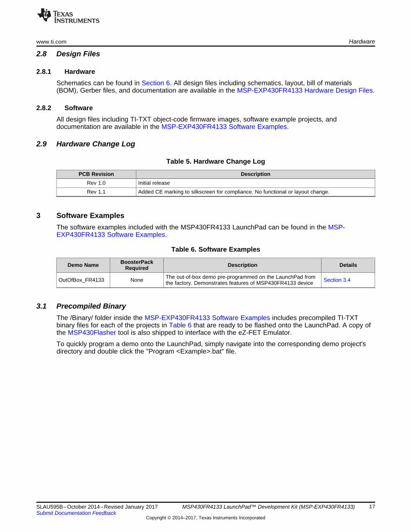
3.1 Precompiled BinaryThe /Binary/ folder inside the MSP-EXP430FR4133 Software Examples includes precompiled TI-TXTbinary files for each of the projects in Table 6 that are ready to be flashed onto the LaunchPad. A copy ofthe MSP430Flasher tool is also shipped to interface with the eZ-FET Emulator.
To quickly program a demo onto the LaunchPad, simply navigate into the corresponding demo project'sdirectory and double click the "Program <Example>.bat" file.
Software Examples www.ti.com
18 SLAU595B–October 2014–Revised January 2017Submit Documentation Feedback
Copyright © 2014–2017, Texas Instruments Incorporated
MSP430FR4133 LaunchPad™ Development Kit (MSP‑EXP430FR4133)
Figure 11. Programming the LaunchPad With Program Batch Files
If desired, the "Program <Example>.bat" file can be modified to point to your own projects' binary file.
NOTE: After importing and compiling the software source code in an IDE such as CCS or IAR, theTI-TXT binary files located in the /Binary/ folder are not updated automatically. Copy thenewly compiled binary from your IDE's /Workspace/Project/ directory and replace the"<Example>.txt" in /Binary/ for the batch file to program your own binary file.
3.2 MSP430Ware LibraryThe examples are built upon MSP430 libraries shown below that are available from TI. All libraries areavailable as part of MSP430Ware. Downloading CCS includes MSP430Ware along with TI ResourceExplorer.• Driver library (MSP430DRIVERLIB): a foundational MSP430 software library that is useful for
interfacing with all MSP430 core functions and peripherals, especially clocks and power.• Graphics library (MSP430-GRLIB): a library for interfacing MSP430 devices to dot-matrix LCD displays.
Contains primitives for simple drawing as well as images and more.• Capacitive Touch Library (CAPSENSELIBRARY): a library for capacitive touch sensing applications.
This library supports the use of buttons, sliders, wheels and more. Highly configurable for eachapplication.
When you begin your own development, you will need more information about these libraries than can beincluded in this user's guide. All of the information that you need is in MSP430Ware or the specific librarydocumentation linked above.
3.3 Development Environment RequirementsTo use any of the software examples with the LaunchPad, you must have an IDE that supports theMSP430FR4133 device (see Table 7). For more details on where to download the latest IDE, seeSection 4.3.
Table 7. IDE Minimum Requirements for MSP-EXP430FR4133
Code Composer Studio™ IDE IAR Embedded Workbench™ IDECCS v6.0 or later IAR EW430 v6.10 or later
www.ti.com Software Examples
19SLAU595B–October 2014–Revised January 2017Submit Documentation Feedback
Copyright © 2014–2017, Texas Instruments Incorporated
MSP430FR4133 LaunchPad™ Development Kit (MSP‑EXP430FR4133)
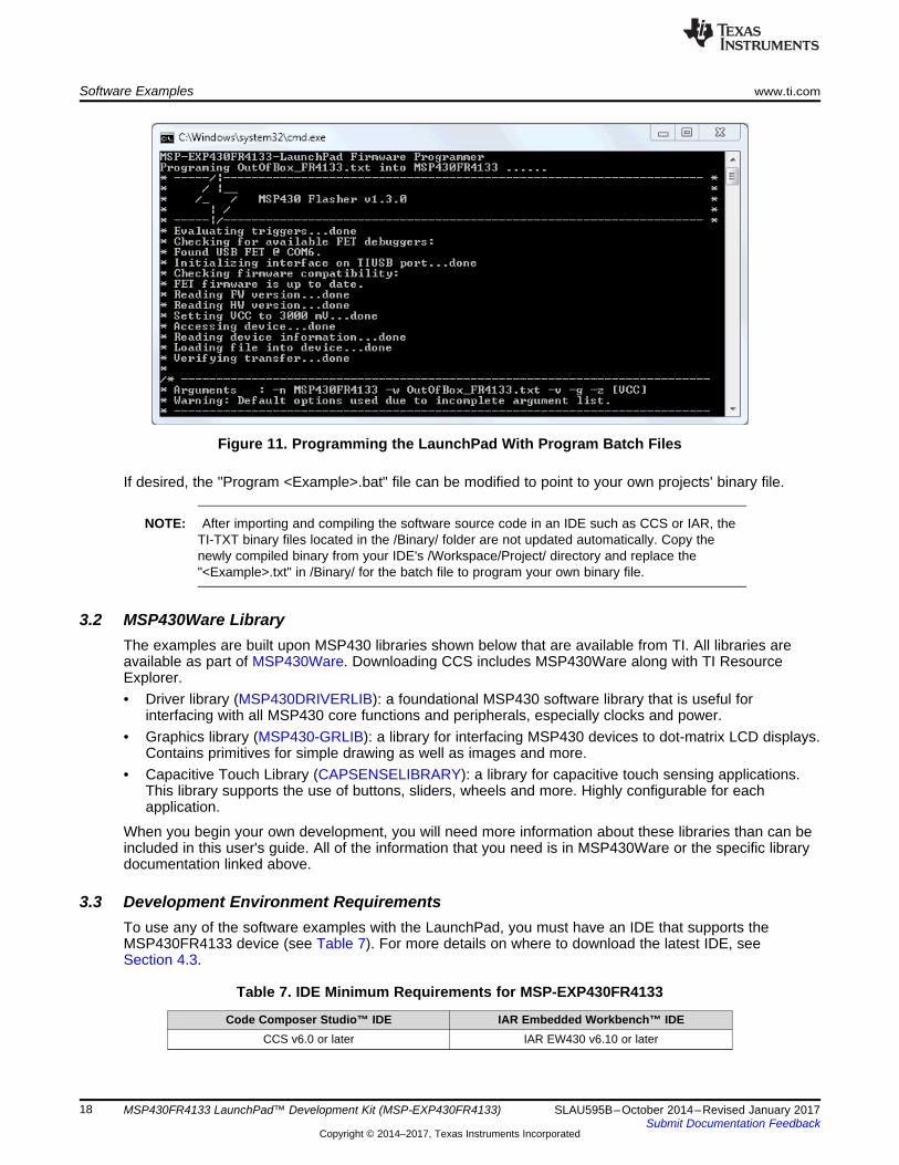
3.3.1 CCSCCS v6.0 or later is required. When CCS has been launched, and a workspace directory chosen, useProject>Import Existing CCS Eclipse Project. Direct it to the desired demo project directory that containsmain.c (see Figure 12). Selecting the \CCS subdirectory also works. The CCS-specific files are locatedthere.
Figure 12. Directing the Project>Import Function to the Demo Project
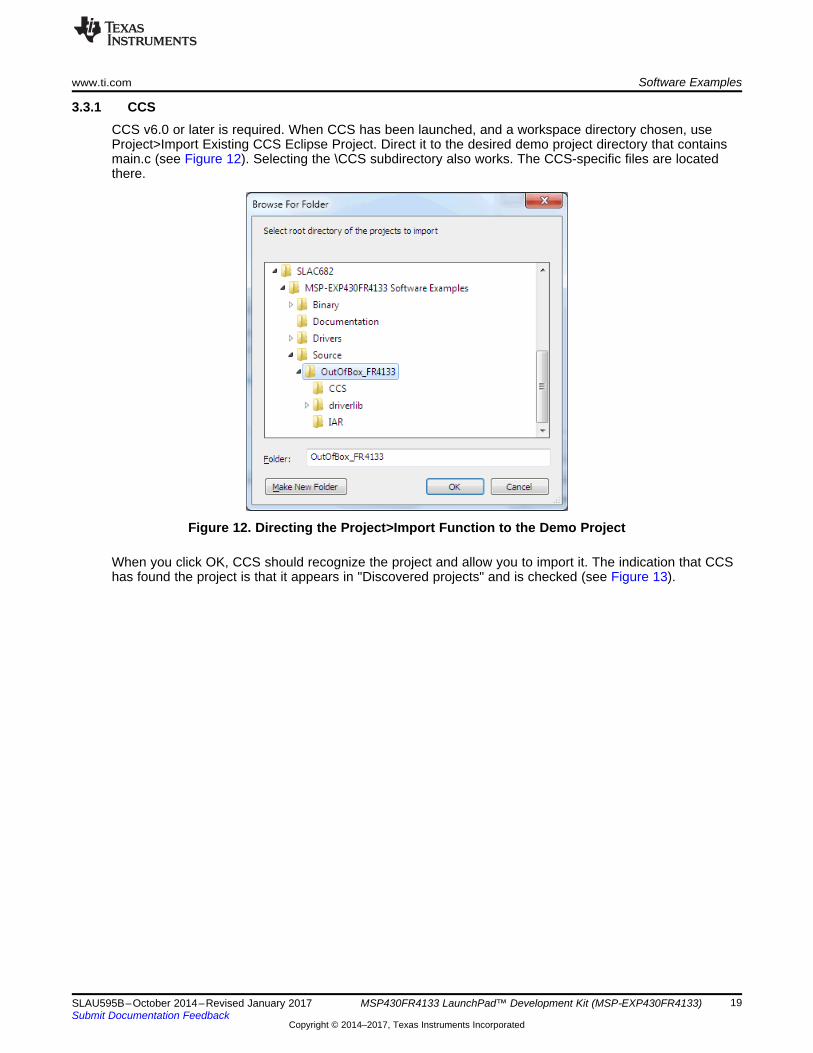
When you click OK, CCS should recognize the project and allow you to import it. The indication that CCShas found the project is that it appears in "Discovered projects" and is checked (see Figure 13).
Software Examples www.ti.com
20 SLAU595B–October 2014–Revised January 2017Submit Documentation Feedback
Copyright © 2014–2017, Texas Instruments Incorporated
MSP430FR4133 LaunchPad™ Development Kit (MSP‑EXP430FR4133)
Figure 13. When CCS Has Found the Project
Sometimes CCS finds the project but does not show a checkmark; this might mean that your workspacealready has a project by that name. You can resolve this by renaming or deleting that project. (Even if youdo not see it in the CCS workspace, be sure to check the workspace directory on the file system.)
3.3.2 IARIAR 6.10 or higher is required. To open the demo in IAR, click File>Open>Workspace…, and browse tothe *.eww workspace file inside the \IAR subdirectory of the desired demo. All workspace information iscontained within this file.
The subdirectory also has an *.ewp project file. This file can be opened into an existing workspace byclicking Project>Add-Existing-Project….
Although the software examples have all of the code required to run them, IAR users may download andinstall MSP430Ware, which contains MSP430 libraries and the TI Resource Explorer. These are alreadyincluded in a CCS installation (unless the user selected otherwise).
3.4 Out-of-Box Software ExampleThis section describes the functionality and structure of the out-of-box software that is preloaded on theEVM.
There are two modes in the out-of-box software, stopwatch mode and temperature sensor mode, whichcan be controlled with S1 and S2 push buttons on the LaunchPad. This demo shows how to utilize theLCD_E module (active in low power mode 3.5), combined with the RTC counter, ADC, and internaltemperature sensor, to implement simple stopwatch and thermometer.
www.ti.com Software Examples
21SLAU595B–October 2014–Revised January 2017Submit Documentation Feedback
Copyright © 2014–2017, Texas Instruments Incorporated
MSP430FR4133 LaunchPad™ Development Kit (MSP‑EXP430FR4133)
3.4.1 Source File StructureThe project is split into multiple files. This makes it easier to navigate and reuse parts of it for otherprojects.
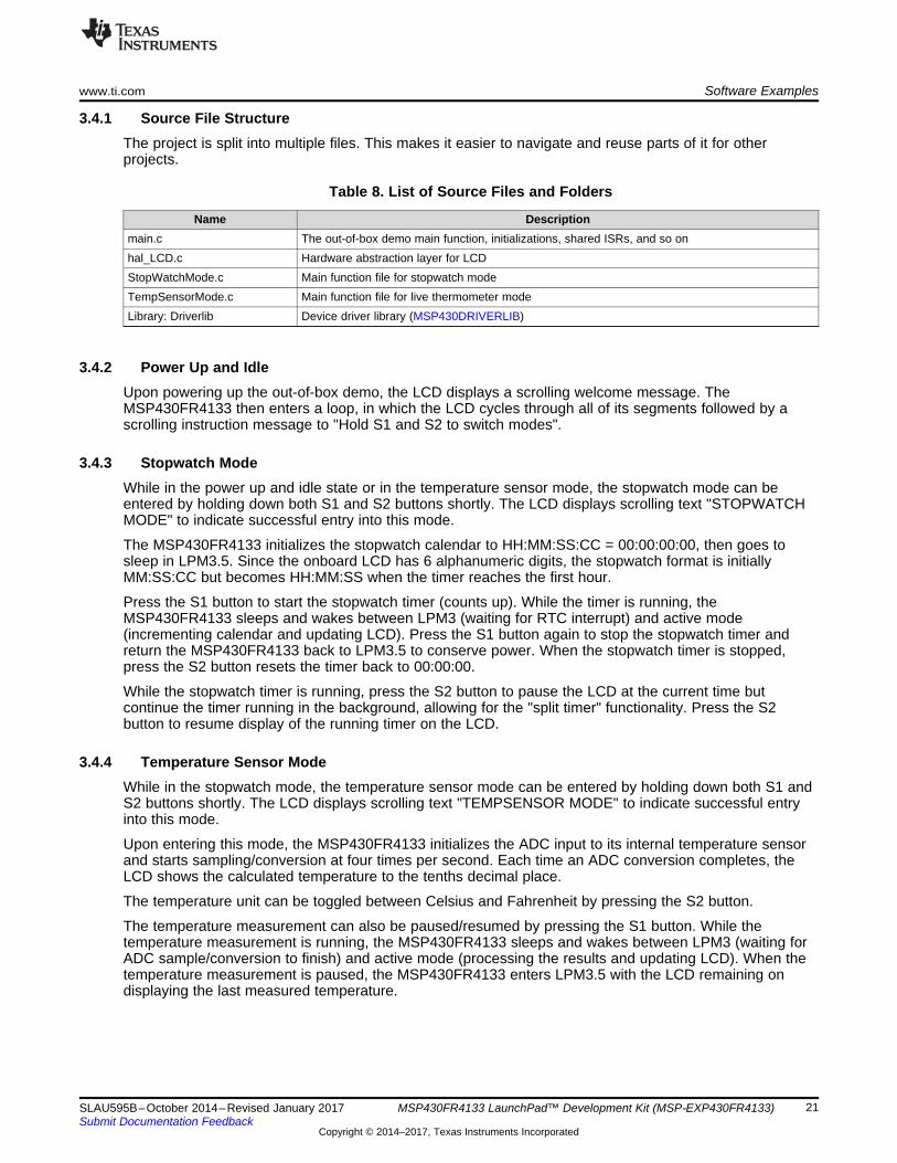
Table 8. List of Source Files and Folders
Name Descriptionmain.c The out-of-box demo main function, initializations, shared ISRs, and so onhal_LCD.c Hardware abstraction layer for LCDStopWatchMode.c Main function file for stopwatch modeTempSensorMode.c Main function file for live thermometer modeLibrary: Driverlib Device driver library (MSP430DRIVERLIB)
3.4.2 Power Up and IdleUpon powering up the out-of-box demo, the LCD displays a scrolling welcome message. TheMSP430FR4133 then enters a loop, in which the LCD cycles through all of its segments followed by ascrolling instruction message to "Hold S1 and S2 to switch modes".
3.4.3 Stopwatch ModeWhile in the power up and idle state or in the temperature sensor mode, the stopwatch mode can beentered by holding down both S1 and S2 buttons shortly. The LCD displays scrolling text "STOPWATCHMODE" to indicate successful entry into this mode.
The MSP430FR4133 initializes the stopwatch calendar to HH:MM:SS:CC = 00:00:00:00, then goes tosleep in LPM3.5. Since the onboard LCD has 6 alphanumeric digits, the stopwatch format is initiallyMM:SS:CC but becomes HH:MM:SS when the timer reaches the first hour.
Press the S1 button to start the stopwatch timer (counts up). While the timer is running, theMSP430FR4133 sleeps and wakes between LPM3 (waiting for RTC interrupt) and active mode(incrementing calendar and updating LCD). Press the S1 button again to stop the stopwatch timer andreturn the MSP430FR4133 back to LPM3.5 to conserve power. When the stopwatch timer is stopped,press the S2 button resets the timer back to 00:00:00.
While the stopwatch timer is running, press the S2 button to pause the LCD at the current time butcontinue the timer running in the background, allowing for the "split timer" functionality. Press the S2button to resume display of the running timer on the LCD.
3.4.4 Temperature Sensor ModeWhile in the stopwatch mode, the temperature sensor mode can be entered by holding down both S1 andS2 buttons shortly. The LCD displays scrolling text "TEMPSENSOR MODE" to indicate successful entryinto this mode.
Upon entering this mode, the MSP430FR4133 initializes the ADC input to its internal temperature sensorand starts sampling/conversion at four times per second. Each time an ADC conversion completes, theLCD shows the calculated temperature to the tenths decimal place.
The temperature unit can be toggled between Celsius and Fahrenheit by pressing the S2 button.
The temperature measurement can also be paused/resumed by pressing the S1 button. While thetemperature measurement is running, the MSP430FR4133 sleeps and wakes between LPM3 (waiting forADC sample/conversion to finish) and active mode (processing the results and updating LCD). When thetemperature measurement is paused, the MSP430FR4133 enters LPM3.5 with the LCD remaining ondisplaying the last measured temperature.
Additional Resources www.ti.com
22 SLAU595B–October 2014–Revised January 2017Submit Documentation Feedback
Copyright © 2014–2017, Texas Instruments Incorporated
MSP430FR4133 LaunchPad™ Development Kit (MSP‑EXP430FR4133)
4 Additional Resources
4.1 LaunchPad WebsitesMore information about the MSP430FR4133 LaunchPad, supported BoosterPacks, and availableresources can be found at:• Tool Folder: resources specific to this particular LaunchPad• TI's LaunchPad portal: information about all LaunchPads from TI for all MCUs
4.2 Information on the MSP430FR4133At some point, you will probably want more information about the MSP430FR4133 device. For everyMSP430 device, the documentation is organized as shown in Table 9.
Table 9. How MSP430 Device Documentation is Organized
Document For MSP430FR4133 Description
Device family user's guide MSP430FR4xx and MSP430FR2xxFamily User's Guide (SLAU445)
Architectural information about the device, including all modulesand peripherals such as clocks, timers, ADC, and so on.
Device-specific data sheetMSP430FR413x Mixed-SignalMicrocontrollers data sheet(SLAS865)
Device-specific information and all parametric information for thisdevice
4.3 Download CCS or IARAlthough the files can be viewed with any text editor, more can be done with the projects if they're openedwith a development environment like Code Composer Studio (CCS) or IAR Embedded Workbench.
CCS and IAR are available in full, free code-size, or time limited versions. The full out-of-box demo can bebuilt with the free versions of CCS and IAR (IAR KickStart), because it is under the code size limit. For fullfunctionality, download the full version of either CCS or IAR.
Go to the MSP430 software tools page to download them and for instructions on installation.
4.4 MSP430Ware and TI Resource ExplorerMSP430Ware is a complete collection of libraries and tools. It includes all of the MSP430 libraries used inthe software examples. By default, MSP430Ware is included in a CCS installation. IAR users mustdownload it separately.
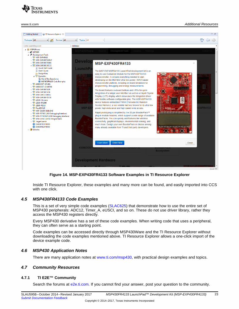
MSP430Ware is built into the TI Resource Explorer, for easily browsing tools. For example, all of thesoftware examples are shown in Figure 14.
www.ti.com Additional Resources
23SLAU595B–October 2014–Revised January 2017Submit Documentation Feedback
Copyright © 2014–2017, Texas Instruments Incorporated
MSP430FR4133 LaunchPad™ Development Kit (MSP‑EXP430FR4133)
Figure 14. MSP-EXP430FR4133 Software Examples in TI Resource Explorer
Inside TI Resource Explorer, these examples and many more can be found, and easily imported into CCSwith one click.
4.5 MSP430FR4133 Code ExamplesThis is a set of very simple code examples (SLAC625) that demonstrate how to use the entire set ofMSP430 peripherals: ADC12, Timer_A, eUSCI, and so on. These do not use driver library, rather theyaccess the MSP430 registers directly.
Every MSP430 derivative has a set of these code examples. When writing code that uses a peripheral,they can often serve as a starting point.
Code examples can be accessed directly through MSP430Ware and the TI Resource Explorer withoutdownloading the code examples mentioned above. TI Resource Explorer allows a one-click import of thedevice example code.
4.6 MSP430 Application NotesThere are many application notes at www.ti.com/msp430, with practical design examples and topics.
4.7 Community Resources
4.7.1 TI E2E™ CommunitySearch the forums at e2e.ti.com. If you cannot find your answer, post your question to the community.
FAQ www.ti.com
24 SLAU595B–October 2014–Revised January 2017Submit Documentation Feedback
Copyright © 2014–2017, Texas Instruments Incorporated
MSP430FR4133 LaunchPad™ Development Kit (MSP‑EXP430FR4133)
4.7.2 Community at LargeMany online communities focus on the LaunchPad – for example, http://www.43oh.com. You can findadditional tools, resources, and support from these communities.
5 FAQQ: I can't get the backchannel UART to connect. What's wrong?A: Check the following:• Do the baud rate in the host's terminal application and the USCI settings match?• Are the appropriate jumpers in place, on the isolation jumper block?• Probe on RXD and send data from the host. If you don't see data, it might be a problem on the host
side.• Probe on TXD while sending data from the MSP430. If you don't see data, it might be a configuration
problem with the eUSCI module.• Consider the use of the hardware flow control lines (especially for higher baud rates).
Q: So the onboard emulator is really open source? And I can build my own onboard emulator?A: Yes! We encourage you to do so. The design files are on ti.com.
Q: The MSP430 G2 LaunchPad had a socket, allowing me change the target device. Why doesn'tthis LaunchPad use one?A: This LaunchPad provides more functionality, and this means using a device with more pins. Sockets fordevices with this many pins are too expensive for the LaunchPad's target price.
Q: With the female headers on the bottom, the board doesn't sit flat on the table, and I can'tunsolder them. Why did TI do this?A: For several reasons. A major feedback item on previous LaunchPads was the desire for femaleheaders instead of male ones. But simply using female instead is problematic, because compatibility withexisting BoosterPacks would be lost, and some people prefer male headers. So, adding female headerswithout removing male ones satisfies both preferences. It also allows more flexibility in stackingBoosterPacks and other LaunchPads.
Sheet 2Sheet 4,5,6
Sheet 3
Sheet 3 Sheet 3
Sheet 2
Power management
Micro USB type B
eZ-FET
MSP430FR4133BoosterPack Connector
LEDSButtons
LCD
Texas Instruments
Mike Stein
1.1
A
B
C
D
1 2 3 4 5 6
A
B
C
D
1 2 3 4 5 6
Copyright © 2017, Texas Instruments Incorporated
www.ti.com Schematics
25SLAU595B–October 2014–Revised January 2017Submit Documentation Feedback
Copyright © 2014–2017, Texas Instruments Incorporated
MSP430FR4133 LaunchPad™ Development Kit (MSP‑EXP430FR4133)
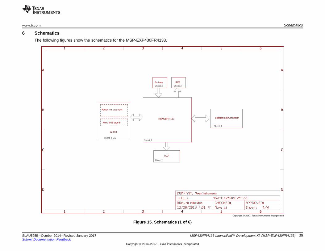
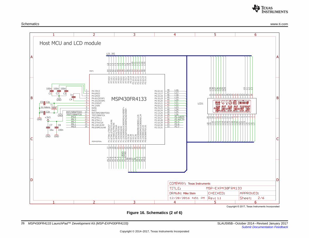
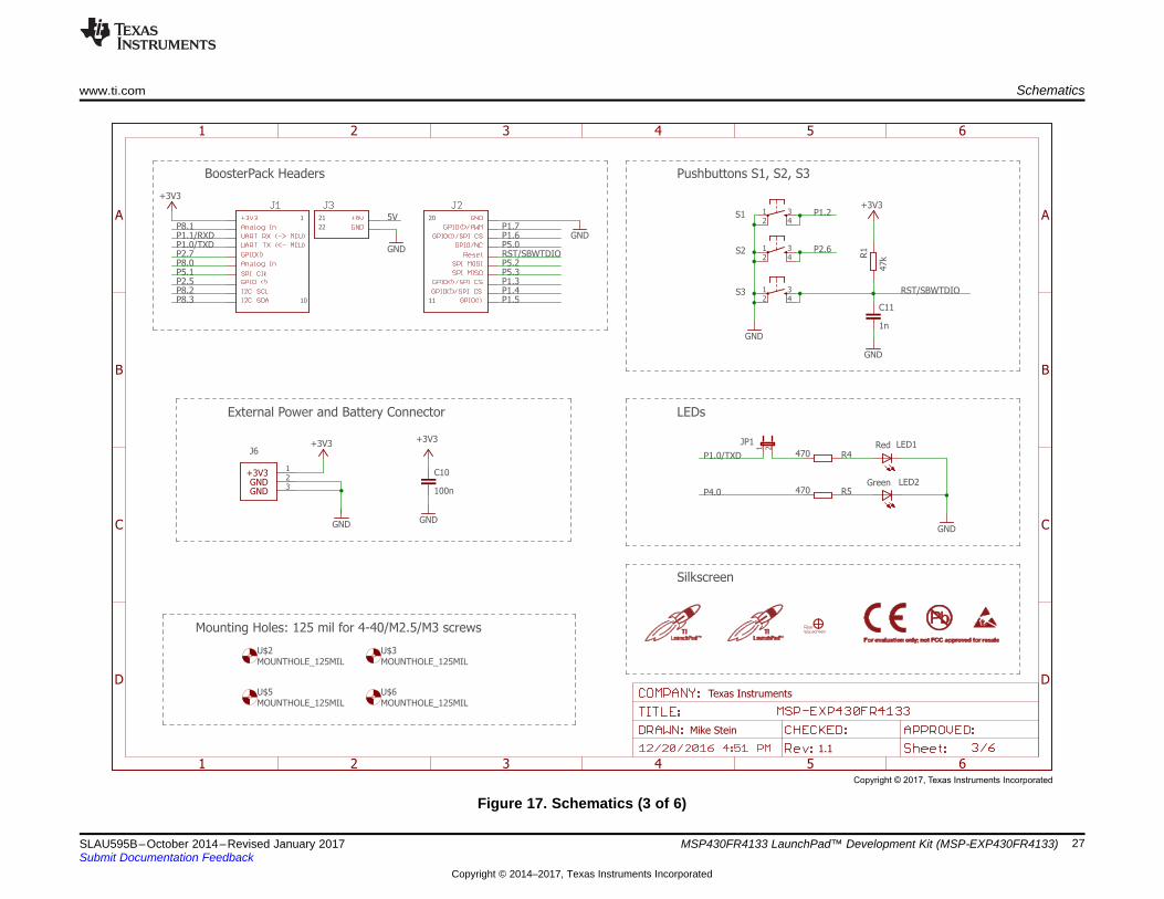
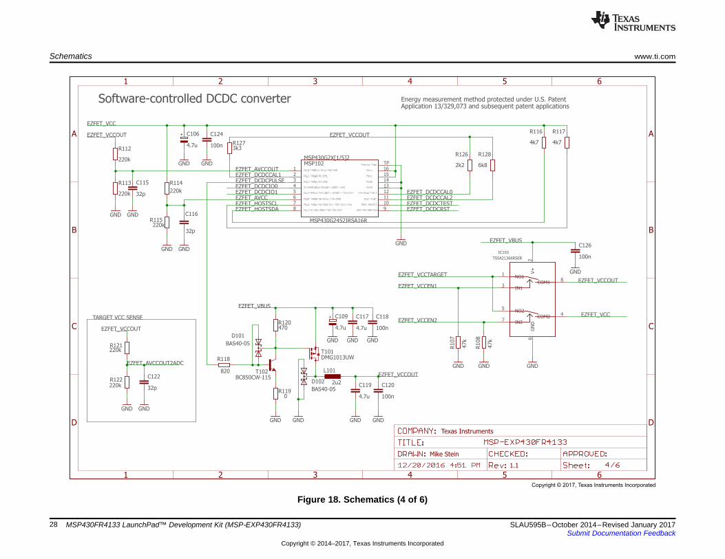
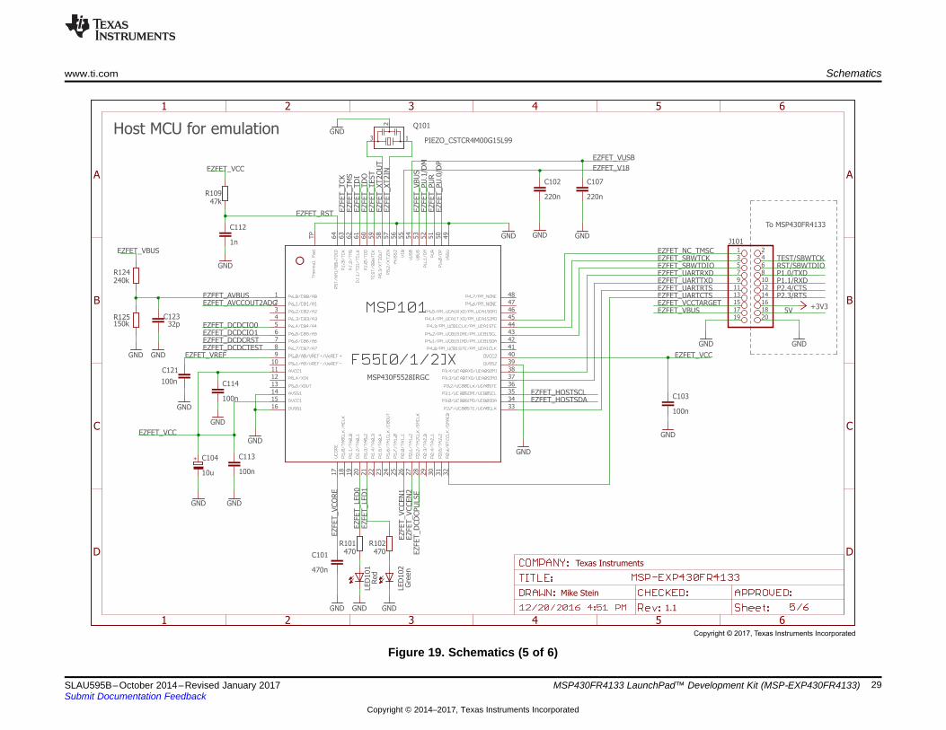
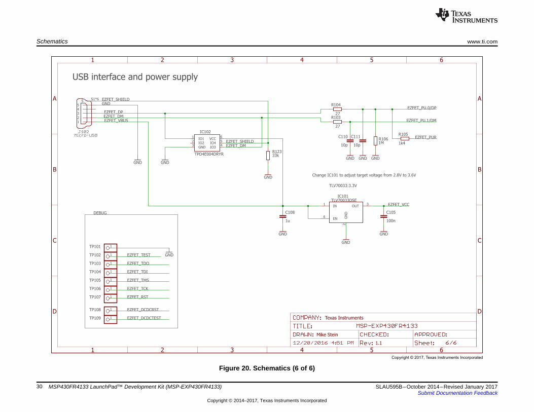
6 SchematicsThe following figures show the schematics for the MSP-EXP430FR4133.
Figure 15. Schematics (1 of 6)
Host MCU and LCD module
MSP430FR4133
100n
GND
100n100n
1u
12p
12p
GND+3V3
10u 100n
GNDGND
GND
32.768kHz
P4.7/R131
P4.6/R232
P4.5/R333
P4.4/LCDCAP14
P4.3/LCDCAP05
P4.2/XOUT6
P4.1/XIN7
DVSS8
DVCC9
RST/NMI/SBWTDIO10
TEST/SBWTCK11
P4.0/TA1.112
P8.3/TA1.213
P8.2/TA1CLK14
P8.1/ACLK/A915
P8.0/SMCLK/A816
P1.7
/TA0.1
/TD
O/A
717
P1.6
/TA0.2
/TD
I/TCLK/A
618
P1.5
/TA0CLK/T
MS/A
519
P1.4
/MCLK/T
CK/A
420
P1.3
/UCA0STE/A
321
P1.2
/UCA0CLK/A
222
P1.1
/UCA0RXD
/UCA0SO
MI/
A1/V
EREF+
23
P1.0
/UCA0TXD
/UCA0SIM
O/A
0/V
EREF-
24
P5.7
/L39
25
P5.6
/L38
26
P5.5
/L37
27
P5.4
/L36
28
P5.3
/UCB0SO
MI/
UCB0SCL/L
35
29
P5.2
/UCB0SIM
O/U
CB0SD
A/L
34
30
P5.1
/UCB0CLK/L
33
31
P5.0
/UCB0STE/L
32
32
P2.7/L3133
P2.6/L3034
P2.5/L2935
P2.4/L2836
P2.3/L2737
P2.2/L2638
P2.1/L2539
P2.0/L2440
P6.7/L2341
P6.6/L2242
P6.5/L2143
P6.4/L2044
P6.3/L1945
P6.2/L1846
P6.1/L1747
P6.0/L1648
P3.7
/L15
49
P3.6
/L14
50
P3.5
/L13
51
P3.4
/L12
52
P3.3
/L11
53
P3.2
/L10
54
P3.1
/L9
55
P3.0
/L8
56
P7.
7/L
757
P7.
6/L
658
P7.
5/L
559
P7.
4/L
460
P7.
3/L
361
P7.
2/L
262
P7.
1/L
163
P7.
0/L
064
MSP1
MSP430FR4x
12345678910
11
12
13
14
15
16
17
18
19
20
21
22
23
24
25
26
27
28
29
30
31
32
33
34
35
36
37
38
LCD1
C3C2C1
C4C5
C6
C7 C8
Y1
L[0..39]
L0
L0
L1
L1
L2
L2
L4
L4
L5
L5
L6
L6
L7
L7
L8
L8
L9
L9
L10
L10
L11
L11
L12
L12
L13
L13
L14
L14
L15
L15
L39
L39
L38
L38
L37
L37
L36
L36
L16
L16
L17
L17
L18
L18
L19
L19
L21
L21
L22
L22
L23
L23
L24
L24
L25
L25
L26
L26L3
L3
RST/SBWTDIOTEST/SBWTCK
P4.0P8.3P8.2P8.1P8.0
P1.7
P1.6
P1.5
P1.4
P1.3
P1.2
P5.3
P5.1
P5.0
P2.5P2.6P2.7
P5.2
L20
L20
P1.0
/TXD
P1.1
/RXD
P2.4/CTSP2.3/RTS
Texas Instruments
Mike Stein
1.1
A
B
C
D
1 2 3 4 5 6
A
B
C
D
1 2 3 4 5 6
Copyright © 2017, Texas Instruments Incorporated
Schematics www.ti.com
26 SLAU595B–October 2014–Revised January 2017Submit Documentation Feedback
Copyright © 2014–2017, Texas Instruments Incorporated
MSP430FR4133 LaunchPad™ Development Kit (MSP‑EXP430FR4133)
Figure 16. Schematics (2 of 6)
1
10 11
2021
22
GND
Green
Red
GND
47k
1n
GND
+3V3
470
470
+3V3
GND
+3V3
GND
100n
+3V3
GND
MOUNTHOLE_125MIL MOUNTHOLE_125MIL
MOUNTHOLE_125MIL MOUNTHOLE_125MIL
GND
Mounting Holes: 125 mil for 4-40/M2.5/M3 screws
BoosterPack Headers Pushbuttons S1, S2, S3
External Power and Battery Connector LEDs
Silkscreen
1 342
S2
1 342
S3
LED2
LED11 2
JP1
R1
C11
R4
R5
C10
1 342
S1
U$2 U$3
U$5 U$6
123
J6
RST/SBWTDIO
RST/SBWTDIOP2.6
P1.2
P4.0
P8.1P1.1/RXD
P2.7P8.0P5.1P2.5P8.2P8.3
P1.6P1.7
P5.0
P5.2P5.3P1.3P1.4P1.5
P1.0/TXD
P1.0/TXD
5V
Texas Instruments
Mike Stein
1.1
A
B
C
D
1 2 3 4 5 6
A
B
C
D
1 2 3 4 5 6
+3V3GNDGND
Copyright © 2017, Texas Instruments Incorporated
www.ti.com Schematics
27SLAU595B–October 2014–Revised January 2017Submit Documentation Feedback
Copyright © 2014–2017, Texas Instruments Incorporated
MSP430FR4133 LaunchPad™ Development Kit (MSP‑EXP430FR4133)
Figure 17. Schematics (3 of 6)
Software-controlled DCDC converter
TARGET VCC SENSE
Energy measurement method protected under U.S. PatentApplication 13/329,073 and subsequent patent applications
MSP430G2452IRSA16R
4k7 4k7
2k2
3k3
6k8
820
0
GND
470
GND
2u2
220k
220k 32p
GND GND
220k
220k 32p
GND GND
220k
220k32p
GND GND
100n4.7u
GNDGND
4.7u 100n
47k
GNDGND
GND
4.7u
GND
4.7u
GND
100n
GNDMSP430G2X[1/5]2
GND
BAS40-05
BC850CW-115
DMG1013UW
BAS40-05
TS5A21366RSER
GND
47k
GND
100n
GND
R116 R117
R126
R127
R128
R118
R119
R120
L101
R121
R122C122
R112
R113 C115 R114
R115C116
C118C117
C119 C120
R107
C109
C106 C124
1234567 10
111213141516
8 9
TPMSP102
D102
T102
T101
D101
NO11
IN13
NO25
IN27
COM18
COM24
V+
2G
ND
6
IC103
R108
C126
EZFET_DCDCTESTEZFET_DCDCRSTEZFET_HOSTSDA
EZFET_HOSTSCL
EZFET_VCC
EZFET_VCC
EZFET_DCDCIO0EZFET_DCDCIO1
EZFET_VCCOUT
EZFET_VCCOUT
EZFET_VCCOUT
EZFET_VCCOUT
EZFET_VCCOUT
EZFET_DCDCCAL0
EZFET_DCDCCAL1
EZFET_DCDCCAL2
EZFET_DCDCPULSE
EZFET_AVCC
EZFET_AVCCOUT
EZFET_VBUS
EZFET_VBUS
EZFET_VCCTARGET
EZFET_VCCEN1
EZFET_AVCCOUT2ADC
EZFET_VCCEN2
Texas Instruments
Mike Stein
1.1
+
+A
B
C
D
1 2 3 4 5 6
A
B
C
D
1 2 3 4 5 6
Copyright © 2017, Texas Instruments Incorporated
Schematics www.ti.com
28 SLAU595B–October 2014–Revised January 2017Submit Documentation Feedback
Copyright © 2014–2017, Texas Instruments Incorporated
MSP430FR4133 LaunchPad™ Development Kit (MSP‑EXP430FR4133)
Figure 18. Schematics (4 of 6)
Host MCU for emulation
To MSP430FR4133
MSP430F5528IRGC
GND
GND
GND
470 470
GND GND
1n
47k
GND
470n
GND
220n
GND
220n
GND
GND
100n
GND
10u
GND
100n
GND
100n
GND
240k
150k 32p
GND GND
100n
GND
GND GND
+3V3
Red
Gre
en
PIEZO_CSTCR4M00G15L99
64
63
62
61
60
59
58
57
56
55
54
53
52
51
50
49
48474645444342414039383736353433
32
31
30
29
28
27
26
25
24
23
22
21
20
19
18
17
16
123456789
1112131415
10
TP
R101 R102
C112
R109
C101
C102 C107
C103
C104 C113
C121
R124
R125 C123
C114
J1011 23 45 67 89 10
11 1213 1415 1617 1819 20
LED
101
LED
102
1
2
3
Q101
EZFET_LED
0EZFET_LED
1
EZFET_VCO
RE
EZFET_AVBUS
EZFET_UARTTXDEZFET_UARTRTS
EZFET_SBWTDIOEZFET_SBWTCK
EZFET_VCCEN
1EZFET_VCCEN
2
EZFET_DCDCIO0EZFET_DCDCIO1
EZFET_RST
EZFET_TCK
EZFET_TM
SEZFET_TD
IEZFET_TD
OEZFET_TEST
EZFET_XT2O
UT
EZFET_XT2IN
EZFET_V18
EZFET_VUSB
EZFET_VBU
S
EZFET_VBUS
EZFET_VBUS
EZFET_PU
.1/D
MEZFET_PU
REZFET_PU
.0/D
P
EZFET_VREF
EZFET_VCC
EZFET_VCC
EZFET_VCCEZFET_DCDCTESTEZFET_DCDCRST
EZFET_HOSTSDAEZFET_HOSTSCL
EZFET_D
CD
CPU
LSE
EZFET_AVCCOUT2ADC
EZFET_UARTRXD
EZFET_UARTCTS
EZFET_NC_TMSC
EZFET_VCCTARGET5V
TEST/SBWTCKRST/SBWTDIOP1.0/TXDP1.1/RXD
P2.3/RTSP2.4/CTS
Texas Instruments
Mike Stein
1.1
+
A
B
C
D
1 2 3 4 5 6
A
B
C
D
1 2 3 4 5 6
Copyright © 2017, Texas Instruments Incorporated
www.ti.com Schematics
29SLAU595B–October 2014–Revised January 2017Submit Documentation Feedback
Copyright © 2014–2017, Texas Instruments Incorporated
MSP430FR4133 LaunchPad™ Development Kit (MSP‑EXP430FR4133)
Figure 19. Schematics (5 of 6)
USB interface and power supply
DEBUG
TLV70033:3.3V
TLV70033DSE
1u
TPD4E004DRYR
27
27
10p 10p
GNDGND
1k41M
GNDGND GND
33k
GND
GND GND
GND
GND
100n
Change IC101 to adjust target voltage from 2.8V to 3.6V
C108
IO11
IO22
GND3
IO34
IO45
VCC6
IC102
R103
R104
C110 C111R105
R106
R123
1TP102
1TP107
1TP103
1TP104
1TP105
1TP106
1TP109
1TP108
1TP101
12345
SS1*6
IN1
EN6
OUT3
GN
D2
IC101
C105
GND
EZFET_VBUS
EZFET_DP
EZFET_DM
EZFET_DM
EZFET_SHIELD
EZFET_SHIELD
EZFET_PU.0/DP
EZFET_PU.1/DM
EZFET_PUR
EZFET_VCC
EZFET_RST
EZFET_TCK
EZFET_TMS
EZFET_TDI
EZFET_TDO
EZFET_TEST
EZFET_DCDCTEST
EZFET_DCDCRST
Texas Instruments
Mike Stein
1.1
A
B
C
D
1 2 3 4 5 6
A
B
C
D
1 2 3 4 5 6
Copyright © 2017, Texas Instruments Incorporated
Schematics www.ti.com
30 SLAU595B–October 2014–Revised January 2017Submit Documentation Feedback
Copyright © 2014–2017, Texas Instruments Incorporated
MSP430FR4133 LaunchPad™ Development Kit (MSP‑EXP430FR4133)
Figure 20. Schematics (6 of 6)
www.ti.com Revision History
31SLAU595B–October 2014–Revised January 2017Submit Documentation Feedback
Copyright © 2014–2017, Texas Instruments Incorporated
Revision History
Revision HistoryNOTE: Page numbers for previous revisions may differ from page numbers in the current version.
Changes from July 21, 2015 to January 17, 2017 ........................................................................................................... Page
• Added Rev 1.1 to Table 5, Hardware Change Log.................................................................................. 17• Updated all figures in Section 6, Schematics ........................................................................................ 25

IMPORTANT NOTICE FOR TI DESIGN INFORMATION AND RESOURCES
Texas Instruments Incorporated (‘TI”) technical, application or other design advice, services or information, including, but not limited to,reference designs and materials relating to evaluation modules, (collectively, “TI Resources”) are intended to assist designers who aredeveloping applications that incorporate TI products; by downloading, accessing or using any particular TI Resource in any way, you(individually or, if you are acting on behalf of a company, your company) agree to use it solely for this purpose and subject to the terms ofthis Notice.TI’s provision of TI Resources does not expand or otherwise alter TI’s applicable published warranties or warranty disclaimers for TIproducts, and no additional obligations or liabilities arise from TI providing such TI Resources. TI reserves the right to make corrections,enhancements, improvements and other changes to its TI Resources.You understand and agree that you remain responsible for using your independent analysis, evaluation and judgment in designing yourapplications and that you have full and exclusive responsibility to assure the safety of your applications and compliance of your applications(and of all TI products used in or for your applications) with all applicable regulations, laws and other applicable requirements. Yourepresent that, with respect to your applications, you have all the necessary expertise to create and implement safeguards that (1)anticipate dangerous consequences of failures, (2) monitor failures and their consequences, and (3) lessen the likelihood of failures thatmight cause harm and take appropriate actions. You agree that prior to using or distributing any applications that include TI products, youwill thoroughly test such applications and the functionality of such TI products as used in such applications. TI has not conducted anytesting other than that specifically described in the published documentation for a particular TI Resource.You are authorized to use, copy and modify any individual TI Resource only in connection with the development of applications that includethe TI product(s) identified in such TI Resource. NO OTHER LICENSE, EXPRESS OR IMPLIED, BY ESTOPPEL OR OTHERWISE TOANY OTHER TI INTELLECTUAL PROPERTY RIGHT, AND NO LICENSE TO ANY TECHNOLOGY OR INTELLECTUAL PROPERTYRIGHT OF TI OR ANY THIRD PARTY IS GRANTED HEREIN, including but not limited to any patent right, copyright, mask work right, orother intellectual property right relating to any combination, machine, or process in which TI products or services are used. Informationregarding or referencing third-party products or services does not constitute a license to use such products or services, or a warranty orendorsement thereof. Use of TI Resources may require a license from a third party under the patents or other intellectual property of thethird party, or a license from TI under the patents or other intellectual property of TI.TI RESOURCES ARE PROVIDED “AS IS” AND WITH ALL FAULTS. TI DISCLAIMS ALL OTHER WARRANTIES ORREPRESENTATIONS, EXPRESS OR IMPLIED, REGARDING TI RESOURCES OR USE THEREOF, INCLUDING BUT NOT LIMITED TOACCURACY OR COMPLETENESS, TITLE, ANY EPIDEMIC FAILURE WARRANTY AND ANY IMPLIED WARRANTIES OFMERCHANTABILITY, FITNESS FOR A PARTICULAR PURPOSE, AND NON-INFRINGEMENT OF ANY THIRD PARTY INTELLECTUALPROPERTY RIGHTS.TI SHALL NOT BE LIABLE FOR AND SHALL NOT DEFEND OR INDEMNIFY YOU AGAINST ANY CLAIM, INCLUDING BUT NOTLIMITED TO ANY INFRINGEMENT CLAIM THAT RELATES TO OR IS BASED ON ANY COMBINATION OF PRODUCTS EVEN IFDESCRIBED IN TI RESOURCES OR OTHERWISE. IN NO EVENT SHALL TI BE LIABLE FOR ANY ACTUAL, DIRECT, SPECIAL,COLLATERAL, INDIRECT, PUNITIVE, INCIDENTAL, CONSEQUENTIAL OR EXEMPLARY DAMAGES IN CONNECTION WITH ORARISING OUT OF TI RESOURCES OR USE THEREOF, AND REGARDLESS OF WHETHER TI HAS BEEN ADVISED OF THEPOSSIBILITY OF SUCH DAMAGES.You agree to fully indemnify TI and its representatives against any damages, costs, losses, and/or liabilities arising out of your non-compliance with the terms and provisions of this Notice.This Notice applies to TI Resources. Additional terms apply to the use and purchase of certain types of materials, TI products and services.These include; without limitation, TI’s standard terms for semiconductor products http://www.ti.com/sc/docs/stdterms.htm), evaluationmodules, and samples (http://www.ti.com/sc/docs/sampterms.htm).
Mailing Address: Texas Instruments, Post Office Box 655303, Dallas, Texas 75265Copyright © 2017, Texas Instruments Incorporated