msc studentenwettbewerbweb.mscsoftware.com/germany/submitted-content/resources/contest... · step...
TRANSCRIPT

MSC StudentenwettbewerbWintersemester 2011/2012
Adams

Aufgaben
Wie viele Freiheitsgrade (Degreesof Freedom) hat das Modell ?of Freedom) hat das Modell ?-------------------------------------Den in Step 10 erzeugten
Command File einschicken.
Software Version: Adams 2011
Files Required: valve.cmd

TUTORIAL
2

• Tips before you start. While working on this exercise, notice:– The use of the right mouse button– The function of single-clicks and double-clicks– The messages on the Status bar– The animation options
• Suggested Exercise Steps1. Import the file valve.cmd2. View the list of keyboard shortcuts.3. Use the zoom shortcut. 4. View the model from different angles.5. Rename the parts.6. Inspect the model.6. Inspect the model.7. Simulate the model.8. Save the Simulation.9. Animate the Results.10.Save your work.

Step 1. Import File
To import a file:
a. Start Adams/View. b. From the Welcome dialog box,
select Import a file.
b
c
select Import a file.c. Click the file folder icon, and the
Select Directory dialog box appears.
d. Find and select the directory Exercise_dir/mod_2_aview_interface.
e. Click OK on the Select Directory Dialog.
f
d
Dialog.f. Click OK on the Welcome Dialog
Box, and the File Import Dialog comes up.
e
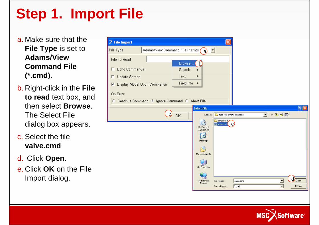
Step 1. Import File
a. Make sure that the File Type is set to Adams/View Command File (*.cmd).
a
b
(*.cmd).
b. Right-click in the File to read text box, and then select Browse. The Select File dialog box appears.
c. Select the file valve.cmd
c
e
d. Click Open.e. Click OK on the File
Import dialog. d

Step 2. View the List of Keyboard Shortcuts
To view the list of keyboard shortcuts:a. Move the cursor away from the model and then right-
click in the Adam/View window. A menu appears listing click in the Adam/View window. A menu appears listing the keyboard shortcuts.
b. To close the menu, left-click away from the menu. c. In the space below, write the shortcut keys for
performing the following view operations.• Rotate:__________________________• Translate:________________________• Zoom with a box:__________________• Zoom into a specific Area:___________• Zoom into a specific Area:___________• Fit:_____________________________• Front View:_______________________
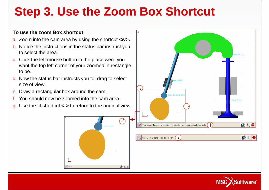
Step 3. Use the Zoom Box Shortcut
To use the zoom Box shortcut:a. Zoom into the cam area by using the shortcut <w>.b. Notice the instructions in the status bar instruct you
to select the area.c. Click the left mouse button in the place were you
want the top left corner of your zoomed in rectangle want the top left corner of your zoomed in rectangle to be.
d. Now the status bar instructs you to: drag to select size of view.
e. Draw a rectangular box around the cam. f. You should now be zoomed into the cam area.g. Use the fit shortcut <f> to return to the original view.
fb
c
e
b
d

Step 4. View the Model from Different Angles
To view the model from the top:a. Use the Top shortcut <T> and the
view changes to a top view.
a
view changes to a top view.
To view the model from the right:b. Use the Right shortcut <R> and
the view changes to the right view.
To view the model in an isometric view:c. Use the Iso shortcut <I> and the
Top View
bc
c. Use the Iso shortcut <I> and the view changes to an isometric one.
If you wish you may continue to try the other shortcut keys.
Right ViewIsometric View
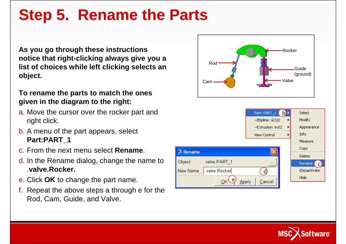
Step 5. Rename the Parts
As you go through these instructions notice that right-clicking always give you a list of choices while left clicking selects an object.
Rod
Cam
Rocker
Guide (ground)
Valve
To rename the parts to match the ones given in the diagram to the right:a. Move the cursor over the rocker part and
right click.b. A menu of the part appears, select
Part:PART_1c. From the next menu select Rename. d. In the Rename dialog, change the name to
Cam Valve
b
cd. In the Rename dialog, change the name to .valve.Rocker.
e. Click OK to change the part name. f. Repeat the above steps a through e for the
Rod, Cam, Guide, and Valve.
cd
e

Step 6. Inspect the Model To inspect the model to determine the number and type of constraints:a. Right-click the small arrow
on the Information tool stack on the right side
a b
stack on the right side of the Status Bar at the bottom of the screen.
b. Select the Model topology by constraintstool.
c. From the Information window that appears, note the number and type of constraints and use them
c
d
constraints and use them to answer Question 1 in the Workshop 2, Review section, page WS2-19
d. Close the Information window.
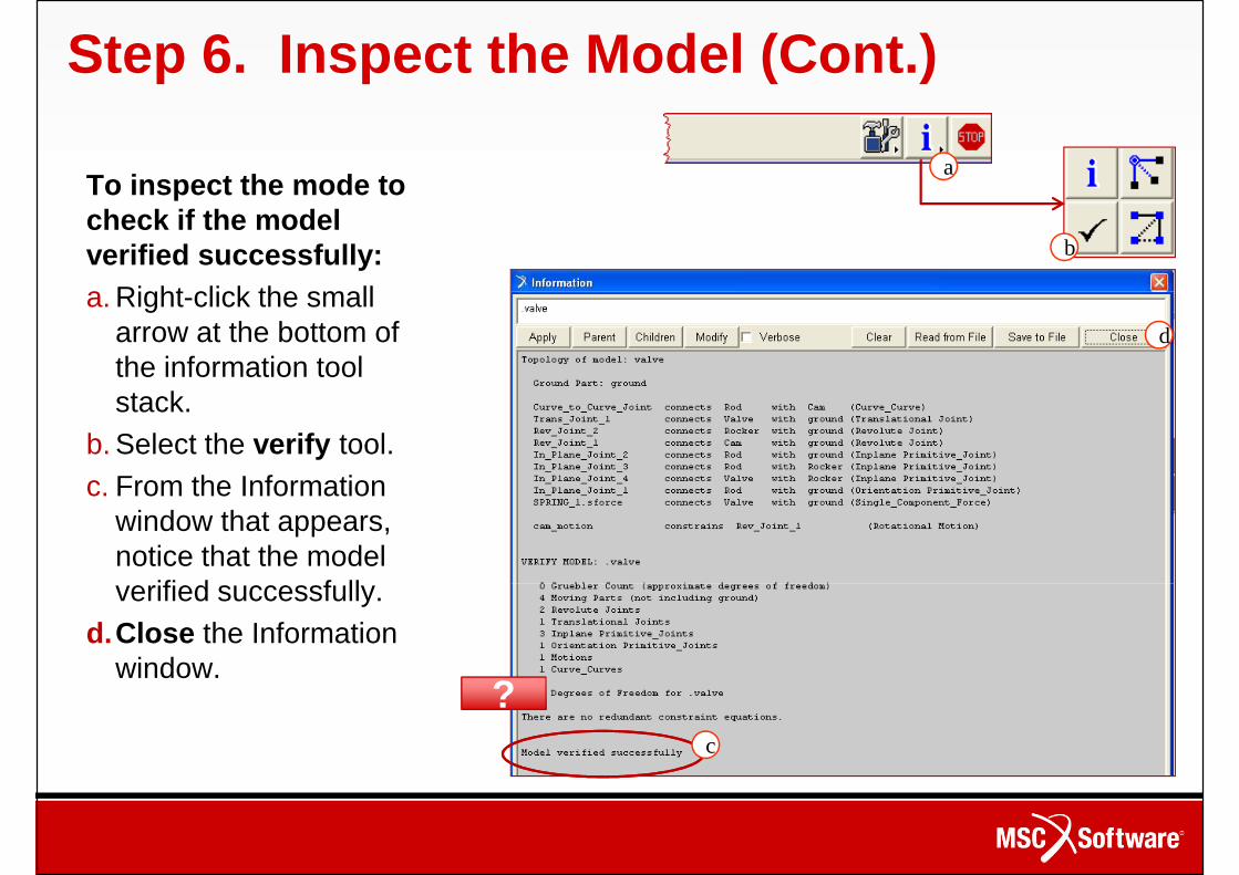
Step 6. Inspect the Model (Cont.)
To inspect the mode to check if the model verified successfully:a. Right-click the small
a
b
a. Right-click the small arrow at the bottom of the information tool stack.
b. Select the verify tool. c. From the Information
window that appears, notice that the model verified successfully.
d
verified successfully.d.Close the Information
window.
c
??

Step 7. Simulate the Model
To run a simulation:a. From the Main Toolbox, select the Simulation
a
a. From the Main Toolbox, select the Simulation tool.
b. In the lower portion of the Main Toolbox, make sure that Default is selected.
c. Select End Time.d. In the text box below End Time, enter 2.e. In the text box below Steps enter 100.f. Click on the Play tool.
b
c
d
fg
f. Click on the Play tool.g. When the simulation is complete, click the Reset
tool.
e
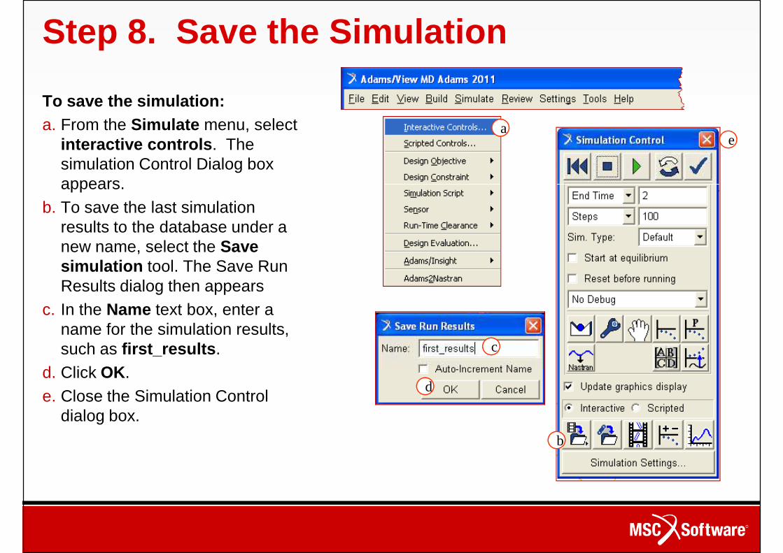
Step 8. Save the Simulation
To save the simulation:a. From the Simulate menu, select
interactive controls. The simulation Control Dialog box appears.
ae
appears.b. To save the last simulation
results to the database under a new name, select the Save simulation tool. The Save Run Results dialog then appears
c. In the Name text box, enter a name for the simulation results, such as first_results.
d. Click OK.
c
d. Click OK.e. Close the Simulation Control
dialog box.
d
b

Step 9. Animate the Results
To Animate the results in the default mode with icons off:a. Select the Animation tool from the Main
Toolbox. aToolbox. b. Notice that the bottom section of the Main
Toolbox changes so that you get the animation tools.
c. To see the animation, click the Play button.d. When the animation is complete, click the
Reset tool.e. To see the animation in incremental steps
click either the +1 to move forward or the -1 to rewind the animation.
a
b
c
d e
fg
to rewind the animation.f. The step number will be listed below the -1
button. g. When finished, click the Reset tool.
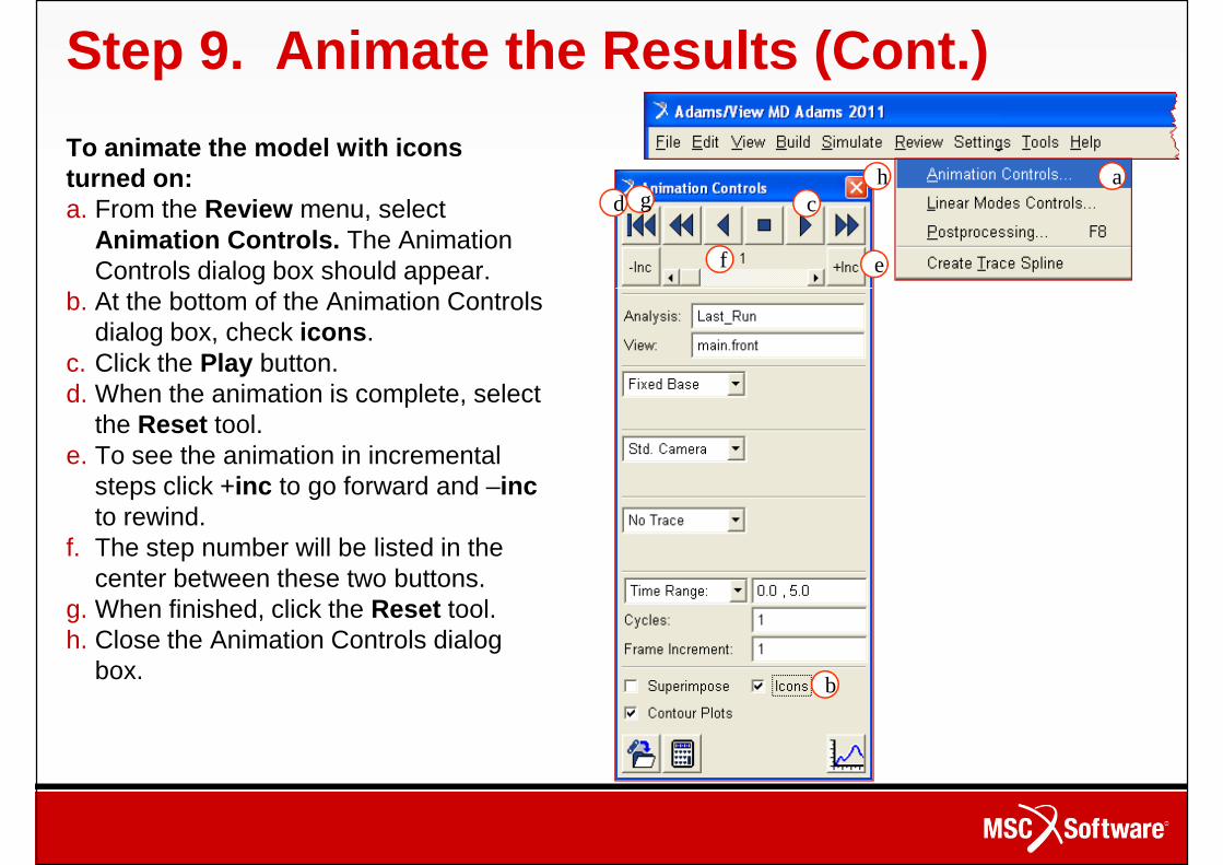
Step 9. Animate the Results (Cont.)
To animate the model with icons turned on:a. From the Review menu, select
Animation Controls. The Animation Controls dialog box should appear.
b. At the bottom of the Animation Controls
acd
e
h
f
g
b. At the bottom of the Animation Controls dialog box, check icons.
c. Click the Play button.d. When the animation is complete, select
the Reset tool. e. To see the animation in incremental
steps click +inc to go forward and –incto rewind.
f. The step number will be listed in the center between these two buttons. center between these two buttons.
g. When finished, click the Reset tool.h. Close the Animation Controls dialog
box. b

Step 10. Save Your Work
To save your work so that the saved file contains only the model contains only the model information:a. From the File menu,
select Export.b. Set File Type to
Adam/View Command File.
c. In the File Name Text box, enter valve1.
d. In the Model Name text
a
b
cd
d. In the Model Name text box, enter valve.
e. Click OK.
e

Schicken Sie die Lösung Schicken Sie die Lösung
bis zum 31. März 2012 an
17