msa-1700222a r2 contract no. de-ac06-09rl14728 attachment library/new... · a-6005-441 (rev 2)...
TRANSCRIPT

A-6005-441 (REV 2)
MSA-1700222A R2 CONTRACT NO. DE-AC06-09RL14728
ATTACHMENT
FUNCTIONAL DESIGN CRITERIA
PROJECT L-845/L-810
CONSOLIDATED FLEET SERVICES
FACILITY HNF-60800, Rev 0
Consisting of 153 pages, including this cover page

Approved for Public Release;
Further Dissemination Unlimited

Approved for Public Release;
Further Dissemination Unlimited
By Janis Braden at 3:49 pm, May 08, 2017
May 08, 2017
DATE:

152
Approved for Public Release;
Further Dissemination Unlimited

Revision 0 HNF-60800
Functional Design Criteria
Project L-845 / L-810
Consolidated Fleet Services Facility
Issued by:
Mission Support
Alliance
May 4, 2017
For the
U. S. Department of
Energy Richland
Operations Office Richland, Washington
PREPARED BY: Jacobs Federal Operations

Revision 0 HNF-60800
1
EXECUTIVE SUMMARY
The Consolidated Fleet Services facilities represents an integrated package of 7 reliability projects for Richland Office, Department of Energy (RL) funding investment in FY17 and FY18, to meet RL Vision 2028 Goals. The proposal features five major areas:
· Cost avoidance opportunity for two new structures plus one remodel in three major projects, plus four small projects with a total estimated of $16,357,000 would avoid spending $1 million in uncontrolled facility annual expenses plus $9 million in backlogged validated projects for needs for 10 facilities. The status quo trend spending scenario will require $16 million in 7 years compared to constructing the new facility complex cost at $16.4 million. The new complex could be delivered at a total cost comparable to the $11.22 million replacement value, plus escalation and added costs of meeting 2016 DOE sustainability requirements for all 10 facilities. See Attachments A and E for replacement value and detailed cost information.
· Compliance opportunity for meeting current U.S. Department of Energy goals standards including freeze the footprint, footprint reduction, workplace safety, fall protection, sustainability, ground water and efficient energy use. See Section 2.9, 4.2.9 and 4.2.10.
· Reduce risk of failure in the cleanup mission for DFLAW, TOC and WTP programs because of a substandard fleet services plant, infrastructure, and facilities condition. This also includes avoiding fleet shop replacement interruptions after vitrification plants are in 24/7 operational mode in FY2023 and beyond.
· Improve quality of workplace conditions for the highly qualified workforce supporting essential roles and mission critical programs.
· Reduced UBS rates as a result of a reduction in the current $1M annual
maintenance cost on facilities needs.
The current facilities complex has an end of life in 2040 to 2045 for 10 existing buildings (36,962 square feet in seven buildings, plus three open air / temporary canvas structures). However, due to existing deficiencies, several major buildings will never achieve target lifespans. Direct and indirect risk of mission failure is now elevated because of so many potential failure factors, deficiencies and poor conditions:
· Heating, ventilation and, air-conditioning needs in every facility.
· Fall protection requirements.
· Electrical loads.
· Lack of outdoor lighting (tent area).
· Overcrowding and lack of safe separations (welding areas).
· Conference room and lunch area of inadequate size for entire staff for safety starts located near the work areas.
· Insulation replacement needed in most of the 2711E.
· Gravel floors in 212ED and 211ED.

Revision 0 HNF-60800
2
· Unpaved laydown and parking areas are not protecting groundwater and need to be paved to meet National Pollutant Discharge Elimination System (NPDES) requirements to implement the Clean Water Act.
· Parking and laydown yard with substandard drainage conditions.
· Inadequate wash down area.
· Inadequate tool box and rolling tool work areas.
· Pit depth and head clearance inadequate in 2711E.
· 15 Temporary storage units currently meet the general lack of permanent storage space.
· Reference manual library space is undersized by half of the required need.
· Parts storage space is undersized by half of the required need.
· Sustainability non-compliance for energy and water consumption targets.
· Lack of customer waiting area near service work order desks.
If RL funds the consolidated fleet services proposal as outlined in HNF-60800 Fleet Services Functional Design Criteria (FDC) report, seven projects implement the integrated proposal:
· L-845, Automobile and Truck Shop Design & Construction a previously defined project with a new description for a 30,900 SF new structure.
· L-XXX, Heavy Equipment Shop Design & Construction, a new project for a 21,600 SF new structure.
· L-810, Body and Paint Booth Shop Design & Construction, a renovation and repurpose of the existing 5,000 square foot shop in 273E structure.
· Four small support projects to provide two permanent storage structures plus two NPDES storm water compliance elements as Design and Construction small projects.
Major Next Actions within a recommended general timeline to implement the Consolidated Fleet Service proposal includes:
· RL acceptance of HNF-60800, Revision, Fleet FDC Report in May 2017.
· MSA will define Scope of Work (SOW) forms with signatures for all 7 projects to match the FDC report assumptions and recommendations
· MSA will prepare a FDC report for project L-810. See Section 6.3.1. for code references and Attachment G. for supporting details.
· RL authorization for L-845, L-XXX and L-810 Design in FY17 budget, including site selection by MSA in June 2017, including modification to RPIP.
· RL authorization of L-845, L-XXX and L-810 Construction in FY18 budget by October 1, 2017.
· RL acceptance of final site selection for 11-acre site by December 2017.
· MSA completion of WIDS, environmental and other clearance reviews by May 2017.
· RL authorization of four small projects for Design & Construction during FY18 budget, coordinated for timing by Mission Support Alliance (MSA) with construction of other three major projects.
· Cancellation of remaining unneeded projects in RPIP and operations budgets, following authorization of all 7 projects for consolidated complex, eliminating $9 million in one-time expense, plus $1 million a year in unplanned facility need responses.
· MSA delivery of L-810 for first completion in sequence to facilitate move-out of 273E.

Revision 0 HNF-60800
3
· MSA move coordination to move-out of 273E to enable renovation after L-810 is available to move-in.
· Move-Out of MO-414, 4722C and 2711E to finish relocation into new complex on 11-acre site in early FY19.
· MSA completion of facility commissioning during FY2019 and project close outs.

Revision 0 HNF-60800
4
Table of Contents
EXECUTIVE SUMMARY ............................................................................................................1
1 INTRODUCTION ..................................................................................................................9
1.1 Document Purpose ......................................................................................................9
1.2 Document Initiation ....................................................................................................9
1.3 Background ...............................................................................................................10
1.4 Site Planning Assumptions .......................................................................................11
1.5 Mission and Scope ....................................................................................................11
1.6 Site Location .............................................................................................................12
1.7 Anticipated Design / Construction Schedule ............................................................12
1.8 Delivery Approach ....................................................................................................13
2 FUNCTIONS .......................................................................................................................13
2.1 Methodology and Justification ..................................................................................13
2.1.1 Methodology ..............................................................................................13
2.1.2 Justification ................................................................................................13
2.2 Safety Class, Safety Significant, or General Service Identification .........................14
2.3 Unique Environmental Protection Requirements .....................................................15
2.4 Materials of Construction .........................................................................................15
2.5 Waste Generation and Management During Construction and Operations ..............15
2.6 Design Life................................................................................................................16
2.7 Special Operation and Maintenance Requirements ..................................................16
2.8 Special Safeguards and Security Requirements ........................................................16
2.9 Energy and Water Conservation Methodologies ......................................................17
3 PROJECT INPUTS ..............................................................................................................18
3.1 Existing Systems, Structures, and Components and Design Baselines ....................18
3.2 Design Assumptions and Constraints .......................................................................18
3.3 Operational Scenarios ...............................................................................................18
3.3.1 Baseline Scenario – Status Quo or No Action Towards Construction of a standalone New Consolidated Fleet Maintenance Facility .................18
3.3.2 Scenario “A” – Standalone - New Consolidated Fleet Maintenance Facility .......................................................................................................19
3.3.3 Scenario “B” – New Smaller Consolidated Fleet Maintenance Shop and Renovation of the 273E Facility ........................................................19
3.3.4 Scenario “C” – 273E + New Shop .............................................................20
3.4 Building Configuration Options ...............................................................................20
3.4.1 Linear Configuration ..................................................................................20
3.4.2 L-Shaped Configuration.............................................................................21
3.4.3 Service Shop in a Car Dealership ..............................................................24
3.4.4 Central Core Space Arrangement ..............................................................24
3.4.5 Shop Complex Compound .........................................................................25
3.4.6 Site Configuration Options ........................................................................25
3.5 Analytical Hierarchy Process ....................................................................................26
3.6 Post Analytical Hierarchy Process ............................................................................26
3.6.1 Conclusions ................................................................................................26

Revision 0 HNF-60800
5
4 DESIGN CRITERIA ............................................................................................................32
4.1 General Criteria .........................................................................................................32
4.1.1 Site Development .......................................................................................32
4.1.2 Safety .........................................................................................................32
4.1.3 Natural Phenomenon Criteria ....................................................................32
4.1.4 Quality Assurance ......................................................................................34
4.2 Facility Criteria .........................................................................................................34
4.2.1 Civil............................................................................................................34
4.2.2 Structural ....................................................................................................39
4.2.3 Architectural ..............................................................................................41
4.2.4 Mechanical – Heating, Ventilation, and Air-Conditioning ........................54
4.2.5 Mechanical – Plumbing .............................................................................57
4.2.6 Piping – Process .........................................................................................57
4.2.7 Electrical Systems ......................................................................................58
4.2.8 Building Systems .......................................................................................62
4.2.9 Special Systems .........................................................................................62
4.2.10 Landscape and Site Development Program ...............................................62
5 CODES AND STANDARDS ..............................................................................................63
5.1 Federal and State Regulations ...................................................................................63
5.2 DOE Orders and Standards .......................................................................................64
5.3 National Consensus Standards ..................................................................................64
6 GUIDANCE DOCUMENTS ...............................................................................................67

Revision 0 HNF-60800
6
List of Figures
Figure 1 – Linear Concept Plan .................................................................................................... 22
Figure 2 – L-Shaped Concept Plan ............................................................................................... 23
Figure 3 – Dealership Shop and Center Core Shop Concepts ...................................................... 25
Figure 4 – A-1, A-2, B-1, B-2, C-1 & C-2 Scenarios ................................................................... 27
Figure 5 – Fleet Site Plan .............................................................................................................. 28
Figure 6 – Fleet Site Plan – Candidate Sites ................................................................................. 29
Figure 7 – Building 1 – Automotive and Truck Service Facility ................................................. 30
Figure 8 – Building 2 – Heavy Equipment Services Facility ....................................................... 31
Figure 9 – FY17 Draft ISAP Fleet Services Roadmap ................................................................. 33
Figure 10 – Building 1 Administrative Area ................................................................................ 46
Figure 11 – Building 2 Administrative Area ................................................................................ 47
List of Tables
Table 4-1 Building Functional Areas – Electrical Hazard Classification and Ventilation Requirements ................................................................................................................................ 58
Table 5-1 Applicable Federal and State Regulations .................................................................... 63
Table 5-2 Applicable DOE Orders and Standards ........................................................................ 64
Table 5-3 National Consensus Standards ..................................................................................... 64
Table 6-1 Fleet Maintenance Shop/Facilities Planning & Design Guidance Documents ............ 67
Table 6-2 Sustainability / Energy / Water Savings Guidance Documents ................................... 68
Table 6-3 Paint Spray Booth - L-810/ HVAC Guidance Documents ........................................... 68

Revision 0 HNF-60800
7
List of Attachments
A – List of Existing Fleet Services Facilities (Appendix A, HNF-60164)
B – Support Graphics Developed during FDC Effort
C – Condition Assessment, 2711 Complex / 273E / 4722C (Appendix C, HNF- 60164). Other major condition assessment excerpts will be included in this Appendix section, described as follows:
· Fall protection requirement assessment findings (Summary Memo C-1 about Dana Engineering report, August 2016)
· HVAC systems replacement needs in all buildings (Summary Memo C-2)
· Electrical system evaluation in FY2016 (Summary Memo C-3)
· Evaluation of two existing Pits located in the 2711 Complex for depth and head clearance (Summary Memo C-4)
D – Kickoff Meeting List of Attendees and Meeting Notes
E – Probable Costs of Baseline Scenario and New Consolidated Shop Scenario F – Results of Analytical Hierarchy Process 60% Workshop – March 16, 2017 G –Recommendation & Costs for One Paint Spray Booth in a New Fleet Facility Complex (Summary Memo G-1)
H –Alternative Sites for Consolidated Fleet Services Complex (Summary Memo H-1)

Revision 0 HNF-60800
8
Acronyms and Abbreviations
ACI American Concrete Association ADAAG Americans with Disabilities Act Accessibility Guidelines ADT Average daily traffic count AFF Above Finished Floor AHP Analytical Hierarchy Process ANSI American National Standards Institute ASHRAE American Society of Heating, Refrigerating, and Air-conditioning Engineers ASME American Society of Mechanical Engineers AWS American Welding Society BMP Best Management Practices cfm cubic feet per minute CFR Code of Federal Regulations CNG Compressed Natural Gas CMU Concrete Masonry Unit DOE U.S. Department of Energy FDC Functional Design Criteria FIMS Facilities Information Management System FY Fiscal Year HVAC Heating, Ventilation, and Air-Conditioning IBC International Building Code IP Inch/pounds ISAP Infrastructure and Services Alignment Plan Jacobs Jacobs Federal Operations LED Light Emitting Diode LEED Leadership in Energy and Environmental Design MSA Mission Support Alliance, LLC NEC National Electric Code NFPA National Fire Protection Association NPDES National Pollutant Discharge Elimination System OSHA Occupational Safety and Health Administration PV Photovoltaics RADCON Radiation Contamination RCW Revised Code of Washington RL Richland Office, Department of Energy RH Relative Humidity RMA Radiological Material Area SSC Systems, Structures, and Components SF Square feet SWPPP Storm Water Pollution Prevention Plan UIC Underground Injection WAC Washington Administrative Code

Revision 0 HNF-60800
9
1 INTRODUCTION
1.1 Document Purpose
This document provides the Functional Design Criteria (FDC) for the replacement of the existing fleet services facilities in one consolidated complex configuration location in the 200 East area of the Hanford site owned by the U.S. Department of Energy (DOE) Richland Office (RL). The fleet services operation is managed by the mission support contractor, Mission Support Alliance, LLC (MSA).
1.2 Document Initiation
The FDC effort begins with a recent DOE RL/MSA staff decision to define a consolidated fleet complex capable of meeting facility needs for the next 40 years of mission support operations. The current facilities complex has an expected end of life during the period 2040 to 2045 for most existing buildings. However, there are numerous documented existing deficiencies in several major buildings that will prevent DOE RL from ever achieving the full target design lifespans of most of the ten existing facilities including:
· Heating, ventilation and, air-conditioning (HVAC) needs in all facilities in a wide range of need areas (like kind replacements, restoration to original target specifications, leakage at doors, sizing, test and balance, inadequate performance, controllers, schedule, energy consumption, service interval frequency, component failures, time out of service each year, etc.).
· Insulation replacement in most of the 2711complex.
· Addition of paved floors in 212ED and 211ED.
· Addition of paved laydown and parking areas to protect groundwater and meet National Pollutant Discharge Elimination System (NPDES) requirements.
· Parking and laydown yard drainage conditions.
· Inadequate wash down area.
· Inadequate tool box and rolling tool work areas.
· Pit depth and head clearance inadequate in 2711.
· Temporary storage used to meet lack of permanent storage.
· Reference manual library space is undersized by half of the required need.
· Parts storage space is undersized by half of the required need.
· Overcrowding and lack of safe separations (welding areas).
· Sustainability lack of compliance for energy and water consumption targets.
· Lack of customer waiting area near service work order desks.
· Conference room and lunch area of adequate size for entire staff for safety starts located near the work area.
The FDC is based on major documents and guidance prepared during FY2016 and FY2017 including: HNF-60164, Revision 0, Fleet Services Facilities Master Plan report showing needs for FY2021 and FY2025, Scope of Work for HVAC replacements are needed in all 200 East area fleet facilities, and Scope of Work for the Spray Paint Booth relocation from 400 area to 200 East area into an existing or a new fleet building.

Revision 0 HNF-60800
10
With regard to the Spray Paint Booth, the Hanford site has and uses two spray booth units currently:
· Fleet – Located in the 400 Area in Building 4722C, slated to move to Building 200E and next into 273E under project L-810.
· Property Services in Building 2715EC – This facility has upgrade needs defined in a report included in Appendix G. The facility has been out of service for several months. MSA placed this one project on-hold to enable evaluation of both needs in this report.
In the start-up of the Fleet FDC effort, the consultants Jacobs Federal Operations (Jacobs) were tasked by MSA Engineering staff on February 23, 2017 to consider whether both spray booth needs can be served in only one new booth ahead. The expense of the various support systems needed to fully operate one spray booth in full code compliance (HVAC, mechanical, gas, fire protection, air quality, etc.) are considerable.
This report includes a recommendation to combine two existing paint booths serving two MSA work groups (Fleet Services, Property Services) into one paint booth going forward. Refer to Attachment G for a summary of the discussion and considerations regarding a merged single paint booth facility. Memo G-1 includes a layout of the floor plan of the 273E before and after project L-810 as required to repurpose and modernize the current structure 273E into 2 body shop spaces, 2 detailing spaces and 2 paint spray booths plus storage and support areas. The floor plan layout of the remodel for 273E will be further refined during preparation of a FDC report plus a final design phase of project L-810. The pre-design code considerations for paint spray booth are included in this report in Section 6 References list and in Attachment G, Memo G-1 for more details.
1.3 Background
There are ten existing fleet facilities that total 36,962 square feet (SF) including 7 permanent and enclosed structures, plus two canvas structures and one roof only no walls. See Attachment A for more details, and Attachment C for deficiencies and existing conditions. The main fleet complex north of 4th Street, west of Baltimore in the 200 East area is completely occupied by 44 MSA Fleet Services staff. In addition office space at MO-414 is occupied by six staff. The majority of the existing facilities were installed during 1976 to 1993. For the most part, the existing fleet shops have performed remarkably well, yet all facilities are now in various stages of overcrowding due to handling more volume compared to original designs and loads. All facilities are nearing end of design life for the asset class yet each facility has one or more major building system deficiencies or faces new regulation non-compliance (sustainability performance, fall protection, ventilation, etc.). During FY2016, frequent repairs and replacements have been reported for garage doors, HVAC units, restroom ventilation, and electrical supply. The limitations of the existing facility condition are symptomatic of scheduling a larger volume of staff and a larger service volume compared to the facility size, configuration, and capacity. The Fleet Services operation is supported by 50 staff currently and is expected to increase to 60 persons. For more detail about the size and scale of fleet services operations, maintenance, as well as discussion of existing condition assessment, known risks, and planned projects, refer to HNF-60164, Revision 0, Fleet Services Facilities Master Plan report.

Revision 0 HNF-60800
11
This FDC report is organized according to policy guidance in MSC-PRO-ENG-8258, Rev. 3, Functional Requirements, Documents, and Functional Design Criteria.
1.4 Site Planning Assumptions
The site plan assumption is that the 200 East area is the best long term location for most fleet activities for the next 40 years of mission needs. Two available existing sites were considered and summarized in this report are:
· 4th Street & Baltimore Avenue, northeast corner, 13 acres in a rectangular shaped site, east of MO-414.
· 3rd Street & Atlanta Avenue, 11 acres in an L-shaped site located south and south east of 273E facility, between the existing rail road track and existing two lane road pavement now in restricted status.
The number of alternative sites was expanded to a total of six candidate sites after initial considerations.
Each repair or service work bay is equipped to handle a large range of functions. To accommodate flexibility, standard automotive and truck repair service bays are designed with at least 15 feet vertical clearance, enabling hydraulic automobile lifts (hoists) set in the floor for a few bays used for passenger vehicles, sport utility vehicles, and light duty trucks. Large heavy equipment repair work bay size will be 16 feet wide by 30 feet long, plus aisle space along both sides and also along the front end for rolling toolboxes plus diagnostic units.
For large work bays serving heavy equipment, the option for drive-thru from an entry door to exit door provides double service bays at 16 to 18 feet wide by 80 feet in length which will be the standard to accommodate cabs and trailers, large trucks, and truck mounted cranes. Seven basic configuration concepts are described in Section 3.5. The most promising layout concepts on Figures 1 and 2 were further developed between the 30% and 60% phase for cost comparison using Analytical Hierarchy Process (AHP) ranking and scoring based on the 60% phase submittal. Parking area sizing is shown in plan diagram on Figure 4. The total complex size is estimated at 11 acres. Approximately 1.17 acres shall be dedicated to building footprint for new consolidated shop structures. Approximately 9.83 acres shall be dedicated for paving for parking, storage units, access drives, vegetative screening, and storm water infiltration areas.
1.5 Mission and Scope
It is the intent for this FDC document is to define three reliability projects (L-845, L-810 and L-XXX) to install one complete, independent, consolidated complex to fully replace all 10 existing fleet services facilities plus one shared office in MO-414 to assure a next service period for the next 40 years of supporting the Hanford cleanup mission. Within the 40 year service life ahead, the first 20 years mainly supports continuation of River Corridor cleanup along with the Tank Operating Contract and ground water pump and treat programs. The next years 21 through 40 will be mainly supporting low level and high level waste plant operations located in the 200E Area, plus Central Plateau cleanup within 200 E and 200 W Areas. The two vitrification plants are expected to be operating for 40 years following each plant start-up by FY2023 and by FY2034 target dates, respectively.

Revision 0 HNF-60800
12
The scope of work will be accomplished by redefining Projects L-845, L-XXX and L-810 while eliminating other defined reliability projects and maintenance activities otherwise needed for 10 existing facilities.
The FDC effort is limited by several factors:
· The FDC document relies on best available information prepared by MSA combined with Jacobs staff knowledge about DOE facilities and fleet shop facilities.
· The FDC document does not repeat primary investigations or condition assessments already performed.
· No invasive or destructive testing of existing facilities was included.
· The FDC document responds to readily observed conditions (for example, peeling insulation on 2711 interior walls) and no effort was dedicated to detect latent or hidden conditions.
· The FDC document relies on facility condition assessments recently performed, mostly during FY2016. Refer to Appendix C for photos of major facilities plus Memos C-1 through C-4 for deficient conditions in fall protection, plus major building systems HVAC, electrical, and pits.
1.6 Site Location
The 10 existing facilities are located north and south of 4th Street at the intersection of Atlanta Avenue in the 200 East area plus the 4722C building in 400 Area. Building 4722C is slated to be taken out of service as the fleet services complex consolidates in 200 East area. Additionally, the western portion MO-414 is used by six staff for Fleet Management offices.
1.7 Anticipated Design / Construction Schedule
The final design is not yet scheduled. With delivery of the FDC document by May 2017, the design could be completed by December 2017, assuming DOE RL authorization to proceed.
A variation of Option C.2 (refer to Section 3.3.4) can be implemented as two separate stand-alone major shop facilities plus 273E repurposed for body and paint shop plus minor support structures. This strategy enables phase out from all 10 existing buildings into one consolidated compound of new facilities below the threshold of Congressional line item approval actions. Design and approvals could start in FY2018, and the first package of construction can be anticipated to begin during 2018 and be completed by October 2019, followed by build-out of the complex by FY2019. An essential schedule coordination item is to have the replacement space completed prior to move out of existing buildings. This critical funding and project execution sequence requires completion of L-845 Auto/Truck Shop (Building 1) prior to start of L-810 modernization. Completion of L-845 is required to move out of 273E before starting L-810. Completion of the proposed Heavy Equipment Shop (Building 2) prior to move out of the 2711E complex. The selected option prepared in response to the March 16 AHP ranking and scoring reflects two facilities depicted on Figures 7 and 8 in one complex of 11 acres in size as shown on Figure 4.

Revision 0 HNF-60800
13
1.8 Delivery Approach
This FDC report is a conceptual design performed by MSA reach back licensed professionals in architecture consistent with Revised Code of Washington (RCW) 18.08, landscape architecture consistent with RCW 18.96, and engineering consistent with RCW 18.43 along with staff resources provided by Jacobs staff. The licensed professional team provides the skills of architectural programming and design, facility planning, master planning and site planning skills plus cost estimation, and specification tasks. The final design consistent with the FDC may be provided by the same reachback consultant delivery method as the FDC report delivery. The construction by general contractor is presently planned for competitively bid, fixed price method. In addition, the Certified Energy Manager participated to assist with defining and reviewing sustainability compliance to meet the applicable sections of the May 2016 DOE guidance shown in Section 2.9.
2 FUNCTIONS
2.1 Methodology and Justification
2.1.1 Methodology
The preferred option for replacing the facilities complex is expected to employ conventional construction materials and methods. The methodology provides a competitive cost and a configuration for the least amount of risk to safely install. Additionally, the proposal is compatible with methods and practices commonly used for shops and service facilities to maintain, modify, and repair fleet vehicles and equipment.
The FDC report methodology relies on documents prepared at MSA request or by MSA staff, plus information collected for selected comparable facilities meeting similar requirements, and available industry trend information. Configuration options will be evaluated for RL and MSA preference, optimum layout and functional needs. The FDC utilized the AHP process to rank, prioritize, and down select from six alternatives plus a baseline scenario to one preferred alternative based on floor plan configuration and site location.
2.1.2 Justification
Construction of a new consolidated Fleet Maintenance Facility complex would eliminate the majority of the projected cost required to continue effective operation of the existing Fleet Maintenance 2711 complex.
Currently there are eight reliability projects (L-XXX designation) and four maintenance activities (Z-XXX designation) that total approximately $8 million that are required to continue effective operation of the existing Fleet Maintenance 2711 complex. Refer to Attachment E for a breakdown of estimated cost for each project and activity. The defined projects and activities for known documented deficiencies and needed upgrades are:
· L-772, Electrical Vehicle Recharging Station for 2266E Facility.
· L-773, Electrical Vehicle Recharging Station for 2750E Facility.
· L-810, Install Paint Booth in 273E.
· L-811, Install Sheet Metal Fire Barrier in 2711EA & 273E at Welding Areas.

Revision 0 HNF-60800
14
· L-813, Concrete Pads 211ED & 212ED Tents.
· L-845, New Fleet Maintenance Shop
· L-XXX, 273E Storage Facility.
· L-XXX, 2711E Complex Storage Facility.
· Z-179, 2711E Complex (211 and 212) Electrical Upgrades.
· Z-182, 2711E Complex Storm water drywell
· Z-XXX, 2711E NPDES Storm water Compliance.
· Z-XXX, 2711E Complex Insulation Replacement.
In addition there are three reliability projects (L-XXX designation) and two maintenance activities (Z-XXX designation) that total an additional approximate $1 million of documented needs that are not fully scoped, administratively processed, or estimated beyond a preliminary rough order of magnitude. Refer to Attachment E for a breakdown of estimated cost by project or activity. These projects and activities are:
· L-182, HVAC Replacement in all Fleet Facilities and costs for an associated Engineering Study.
· L-814, Insulation Repair in the 2711 Complex.
· L-XXX, Fall Protection (to meet Occupational Safety and Health Administration [OSHA] January 17, 2017 requirements).
· Z-160, Pit fill-in in one of two existing pits 2711.
· Z-XXX, 273E NPDES Storm water Compliance.
There are also additional Fleet Services goals, objectives, and needs that are not yet met by defined projects and activities. These items are not estimated or scoped above:
· Fleet Services footprint reduction.
· Fleet facilities sustainability.
· Possible changes to the existing Executive Order for sustainability on federal sites, typically modified at the start of each new administration term.
· Additional fill-in of second pit in 2711E based on a comparison to modify two existing pits or abandon one pit or both pits by filling with concrete included under Attachment C.
Finally, a recommendation in this report is to eliminate two spray booths in two buildings (2715EF and 4722C) to operate only one shared spray booth in 273C by implementing L-810 going forward. Refer to Memo G-1 in Attachment G for the analysis. The next step includes preparing a separate functional design criteria report for L-810 based on information included in Table 6-3 and in Attachment G.
2.2 Safety Class, Safety Significant, or General Service Identification
The Fleet Services facilities (and the activities performed within) do not perform any function credited in a nuclear facility safety basis for any of the Hanford site facilities, therefore, no nuclear safety function. This results in a General Service facility classification.

Revision 0 HNF-60800
15
2.3 Unique Environmental Protection Requirements
The design and construction will consider environmental aspects primarily related to the National Environmental Policy Act process. In particular, attention will be given to minimizing impact to any areas of old growth sagebrush and the impact to any biological communities, (i.e., nesting birds, etc.), during the construction effort. The project design will minimize hazardous and non-hazardous waste generation and the use of hazardous materials during construction, operation, and closure. All work shall be performed safely, in a manner that ensures adequate protection for employees, the public, and the environment. All work shall be performed in compliance with environmental requirements of all applicable laws, regulations, and directives as described in MSC-RD-15332 in conjunction with MSC-PRO-15333.
2.4 Materials of Construction
Refer to Section 4 for preliminary construction materials. The materials identified and considered during the FDC effort are shown. Materials may be modified or other materials may be added during final design phase after the completion of the FDC report.
When appropriate for piping, National Sanitation Foundation approved components or coatings shall be specified. Materials used shall also be corrosion resistant in the environment in which they will be used including chemical, galvanic, or other reaction that can occur between materials.
2.5 Waste Generation and Management During Construction and Operations
The excavation equipment uses various oils and lubricants that are removed or changed occasionally from the equipment used on the Hanford site. Service maintenance on contractor’s
equipment shall be performed off-site. Any spills shall be reported and managed in accordance with applicable Hanford site-wide procedures.
Piping equipment and distribution shall be required for two oil delivery systems, two lubrication delivery systems, two hydraulic delivery systems, and one soap delivery system. The actual quantity and exact type of systems various fluids, oils, and lubricants needed for operations shall be defined during design phase after the completion of the FDC report.
The following regulations shall apply:
Vehicle Related Regulations: 10 CFR 851, Worker Safety and Health; 48 CFR 970.5223-1, Integration of Environment, Safety, and Health into Work Planning and Execution; 49 CFR 40, 325, 355-399, Federal Motor Carrier Safety Regulations; and Washington Administrative Code (WAC) 446-65, Commercial Motor Vehicle Regulations.
Fuel Related Regulations: 49 CFR 40, 325, 355-399, Federal Motor Carrier Safety Regulations; WAC 446-65, Commercial Motor Vehicle Regulations; Executive Order 13423 and 13693; WAC 173-360, Underground Storage Tanks; WAC 173-303 and 173-216, Dangerous Waste Regulations.

Revision 0 HNF-60800
16
2.6 Design Life
The design life for the main facilities is targeted for 40 years. For valves and other appurtenances (e.g., air release, pressure gages, pumps, tanks, etc.) design life shall be 20 years. Ease of replacement shall be considered for equipment and systems when a 20-year life is not practical. Major systems including HVAC and roofing shall have a target 20-year service life. Other major facility components shall have a target service life defined based on applicable guidance:
· Lighting for high efficiency – 5 years.
· Water for high efficiency with recycling pumps, filtration, and tanks –15 years.
· Solar photovoltaic (PV) electrical generation units – 15 years.
· Energy management system – 15 years.
· Soap systems for vehicle wash – 20 years.
· Vehicle wash unit – 15 years (pumps 5 years).
· Fluid pumps and tanks – 5 years.
· Hydraulic lifts – 40 years.
· Overhead cranes – 20 years.
· Skylights or natural daylight systems – 20 years.
· Garage doors – 5 years.
· Fluid storage for recycling pick-up – 15 years.
· Sold waste handling (compactor or storage system until picked up) – 40 years.
2.7 Special Operation and Maintenance Requirements
The various special operations and maintenance requirements will be further defined during the final design phase after the completion of the FDC report, based on product research and choices. These include:
· Water for high efficiency with recycling pumps, filtration, and tanks.
· Solar PV electrical generation units.
· Solar film applied to windows to control heat gain in summer.
· Energy management system.
· Soap systems for vehicle wash.
· Vehicle wash unit.
· Fluid pumps and tanks.
· Hydraulic lifts.
· Overhead cranes.
· Skylights or natural daylight systems.
· Fluid storage for recycling pick-up.
· Sold waste handling (compactor or storage system until picked up).
2.8 Special Safeguards and Security Requirements
Not applicable

Revision 0 HNF-60800
17
2.9 Energy and Water Conservation Methodologies
The proposed buildings will be programmed to follow 2016 Guiding Principles for Sustainable
Federal Buildings Updates Crosswalk, dated May 2016 for guidance to include sustainable features. The various energy and water conservation measures and systems will be further defined during final design phase after the completion of the FDC report. These include:
· Lighting for high efficiency, including indoor and outdoor parking lot lighting using light emitting diode (LED) fixtures with ROAM devices for data reporting plus lighting controls (auto shutdown, occupancy sensors, photoelectric cells).
· Water for high efficiency to meet American Society of Heating, Refrigerating, and Air-conditioning Engineers (ASHARE) 189.1, including recycling pumps, filtration, and tanks.
· HVAC system to meet ASHRAE 55 standard current version to either 62.1 or 62.2.
· Solar PV electrical generation from flat panel rooftop units.
· Energy management and controls systems including energy modeling by builder or designer to confirmed system target performance 30% better than ASHRAE 90.1 standard current version as a goal, plus building commissioning process post construction.
· Soap systems for vehicle wash including environmentally friendly soap products.
· Skylights and natural daylight systems, including window film to control heat gain in summer and heat loss in winter and auto operated louvered systems.
· Landscape program using low impact development design approach using reclaimed storm water and with an irrigation system 50% or more below conventional practices using methodologies from ASHRAE 189.1 or current comparable standards. See also Section 4.2.9 & 4.2.10.
· Perimeter planting buffer zone is intended for seasonal windbreak to reduce damage and wear and tear to parked vehicles and equipment in the complex, plus shading for reduction of heat island effects of the paved surface area. This will include indigenous plants with a xeriscape design, requiring minimal irrigation. See also Section 4.2.9 & 4.2.10.
· Wall shading architectural (screens, fins, louvers, green screens, solar film applied to windows) features to reduce heat loads on solid walls or windows facing southeast, south or southwest in summer.
· To meet the requirement for renewable energy, the site annually purchases Renewable Energy Credits, some of which can be assigned to this facility in order to comply with renewable energy requirement.

Revision 0 HNF-60800
18
The DOE guidance requires including sustainability measures based on classification of the proposal as follows:
· Existing Buildings – The 10 existing buildings do not meet most of the 21 criteria in the 2016 Guiding Principles for Sustainable Federal Buildings Updates Crosswalk, dated May 2016. If all 10 existing facilities are fully replaced, each new facility would now be required to meet most of the 21 criteria. However, the full replacement cost value shown in the Facilities Information Management System (FIMS) database at $9.7 million does not include the cost of meeting all current applicable sustainability measures in the 2016 guidance.
· Modernization – This set of criteria is applicable to renovation and changing the function of 273E. A recommendation of the FDC document is to revise the scope of L-810 project prior to the final design phase to include all requirements under ‘Modernization’ in the 2016 DOE guidance whether listed in the FDC document or not, in addition to the changes defined in the L-810 project.
· New Construction – A recommendation of the FDC document is to revise the scope of L-845 project plus one new project number for both proposed shop buildings to include all requirements under ‘New Construction’ in the DOE guidance whether listed in the
FDC or not, in addition to the changes defined in the L-845 project.
3 PROJECT INPUTS
3.1 Existing Systems, Structures, and Components and Design Baselines
The various existing systems, structures, and components (SSC) to be modified are listed in repot text plus Attachment E. The SSC will be further defined during the final design phase after the completion of the FDC report.
3.2 Design Assumptions and Constraints
It is assumed that building codes and OSHA fall protection would be met for all alternatives. However, fall protection in the 2711E complex or 273E has not yet been defined as a retrofit so that this item was included as a probable cost estimates item in Appendix E.
3.3 Operational Scenarios
3.3.1 Baseline Scenario – Status Quo or No Action Towards Construction of a standalone
New Consolidated Fleet Maintenance Facility
Sections 3.3.1 thru 3.6 represents historical information considered by the project team during 30% and 60% phase. Skip ahead to next Section 4 and also look at Figures 5, 6, 7 & 8 for the preferred alternative.
Under the Baseline Scenario, the 10 existing fleet facilities totaling approximately 36,962 SF of enclosed space plus the space in MO-414 utilized for administrative offices, and 3 open air/ temporary structures would be maintained into the future.

Revision 0 HNF-60800
19
The proposed project L-845 would add approximately 12,000 SF to the Fleet Maintenance Facility complex (a new shop at 4th Avenue and Baltimore).
The proposed L-810 project would add approximately 1,021 SF to the existing Fleet Maintenance Shop Complex (if the paint booth goes into the existing facility to replace 2715EC at a size of 1,021 SF).
The technician to work bay ratio would be 1.45 technicians to one service work bay (32 techs to 22 service bays = 1.45 ratio). The ratio is included to measure for overcrowding of shop floor areas, a current problem in 2711E complex as well as in 273E shop building.
However under the Baseline Scenario, current conditions do not meet several major objectives:
· Footprint reduction.
· Efficiency of operations, including safety.
· Cost efficiency.
· Sustainability.
· Overcrowded conditions in 2711E (work bay to work bay separation, parts, library, and lunchroom).
· Lack of permanent storage at 273E and 2711E.
· Interruption of service to replace fleet facilities during 2040 to 2045 in the middle of the vitrification plant operational periods.
3.3.2 Scenario “A” – Standalone - New Consolidated Fleet Maintenance Facility
The concept for Scenario “A” is to construct a new consolidated Fleet Maintenance Facility that would resolve all unmet goals of the baseline condition scenario and increase the total of number of work bays.
The proposal is for 31 or 32 work bays in a new consolidated Fleet Maintenance Facility with a target size of 51,200 SF.
The target ratio for the new facility shall be one technician to one service bay.
Building MO-414 used for administrative offices and the entire 2711 Complex are eliminated from use by Fleet Services. Buildings 4722C and 273E would not be replaced.
The proposed project L-845 and L-810 would both be required to create the new Fleet Maintenance Facility complex.
Other reliability projects and maintenance activities to support needs to effectively operate the 2711 Complex would be eliminated.
3.3.3 Scenario “B” – New Smaller Consolidated Fleet Maintenance Shop and Renovation
of the 273E Facility
The concept for Scenario “B” also involves the construction of a consolidated Fleet Maintenance Shop Complex.
However, the proposed new shop would be approximately 45,000 SF.

Revision 0 HNF-60800
20
In this scenario the 273E facility (5,461 SF with eight work bays) remains in use. The facility would eventually be replaced before the projected end of life year of 2043 with an approximate 4,800 SF addition to one end of the proposed new shop.
The proposed project L-845, L- 810, and remodel of 273E would create the new shop facilities complex.
As in Scenario “A”, other reliability projects and maintenance activities to support needs to effectively operate the 2711 Complex would be eliminated.
Also the ratio for the new facility complex shall be one technician to one service bay.
3.3.4 Scenario “C” – 273E + New Shop
During development of the FDC, MSA Fleet Maintenance staff requested that a Scenario “C” be added.
In this scenario the 273E facility would be repurposed/modernized and one new shop structure will be constructed. The shop may be as indicated in Scenario A and B or could be a smaller shop dedicated to one Fleet Maintenance Facility (i.e., either Automotive/Truck or Heavy Equipment).
Scenario C-1 and C-2 are defined to reflect how four to five facilities would implement the same space allocation totals shown in A.1, A.2., B.1., and B.2. in the range of 45,000 to 51,200 SF total. Sections 3.3 text describes what led to the project team conclusion for the target facility size. At 52,500 SF new complex, plus the 273E body and paint shop were further refined into Figures 7 & 8 plus Attachment G.
3.4 Building Configuration Options
3.4.1 Linear Configuration
This concept utilizes dual entry bays on each side, an administrative center core, segregation of large heavy equipment versus general automotive/truck, provides options for one or two pits or hoists, one wash bay, one combination welding/fabrication shop area with drive-thru and 25 ton crane, and two full length drive-thru work bays. A second story requires two sets of stairs and/or an Americans with Disabilities Act Accessibility Guidelines (ADAAG) accessible elevator. HVAC units on pads would be set in the vicinity of A-9 to A-11 as shown on Figure 1, outside of the building footprint for the anticipated large sizes of a split HVAC system including chillers, condensers, heat pumps, blowers, and heat recovery unit to meet defined needs.
Disadvantage: Building overall length may be a challenge for site size, site shape, and geotechnical support of such a long floor slab.
Built example: Snohomish County Public Works Cathcart Fleet Facility is 36,900 SF (410 feet long by 90 feet wide) designed by Jacobs in 2006 and constructed in 2007 to 2008. The facility is one of 10 buildings totaling 150,000 SF constructed at a cost $34 million within a 20 acre site serving all of Snohomish County, Washington, including the needs for servicing police, environmental, administrative and public works vehicles plus long term parking (impound vehicles), and refueling needs.

Revision 0 HNF-60800
21
3.4.2 L-Shaped Configuration
Dual entry bays on each side, administrative center core at the heel of the L-shape, segregation of large heavy equipment versus general automotive/truck, option for two or four pits or hoists, one wash bay, one combination work fab shop area with drive-thru and 25 ton crane, and two full length drive-thru work bays. A second story requires two sets of stairs and an ADAAG accessible elevator. HVAC units on pads would be set in the vicinity of A-9 to A-11 as shown on Figure 2 outside of the building footprint for the anticipated large sizes of a split HVAC system including chillers, condensers, heat pumps, blowers, and heat recovery unit to meet defined needs.
Disadvantage: Access congestion at the administrative door entry area (E-10 on Figure 1) and at two work bay drives.
Built example: City of Richland Shops at Queensgate Boulevard in Richland, Washington.

Rev
isio
n 0
H
NF
-60
800
22
Fig
ure
1 –
Lin
ear
Co
nce
pt
Pla
n

Rev
isio
n 0
H
NF
-60
800
23
Fig
ure
2 –
L-S
ha
ped
Co
nce
pt
Pla
n

Revision 0 HNF-60800
24
Key factors that are compared for both floor plan configurations shown on Figures 1 and 2 are:
FACTOR LINEAR L-SHAPE
Number of Work bays 32 31
Overall Total Footprint 51,200 SF 51,200 SF
32 Technicians to Number of Work Bays 1.00 Techs / work bay 1.03 Techs / work bay
Automotive and Truck 18 bays 17 bays
Heavy Equipment 6 bays 6 bays
Other Service Bays
(Truck Hoist, Crane, Oil, Fab/Welding, Wash)
8 bays 8 bays
Hand-drawn conceptual block diagrams prior versions of Figures 1 and 2 were shown and discussed on February 23, 2017 at the Kickoff meeting. Refer to Attachment D for data regarding the Kickoff meeting. The concepts were further refined after the meeting, based on customer comments and requests for information, as shown in Figures 1 and 2.
Three other configuration options (dealership, center core, and compound complex) were considered and discussed on February 23, 2017 at the Kickoff meeting. These options are further described below based on a high level evaluation. The service shop in a car dealership concept was selected to be part of the preferred option shown on Figure 7.
3.4.3 Service Shop in a Car Dealership
The service shop in car dealership design incorporates an access drive with a single entry door and single exit door as shown on Figure 7. The configuration includes a central tool area and also an aisle way as well as opportunities for tools stacked against one solid perimeter wall to serve each work bay. All stalls are accessed inside the center of the building using one central drive though a single direction lane between the entry/exit doors. This option offers advantages to eliminate cost and maintenance of numerous doors and loss of heat and cooling at each door seal. The disadvantage is the efficiency of structure size to floor area requiring a wider building size, plus potential for adding more vehicle emissions in the building, and loss of building efficiency by adding more floor space dedicated for drives and safe turning radiuses. The option has main advantages of tool boxes and work benches situated along perimeter walls, a lower cost to build (fewer garage doors and door headers), and slightly lower operating cost (less garage door servicing, less loss or leakage in winter and summer temperatures) to maintain the slightly larger structure compared to Linear and L-shaped on Figures 1 and 2. This configuration is best suited for the automotive/truck service bays in the linear or L-shaped building.
3.4.4 Central Core Space Arrangement
Another service shop layout option is to align all central core spaces (offices, conference room, parts, work service managers, restrooms, mechanical, and electrical space as shown on Figure 3) in the center of the structure to separate each work bay. The main disadvantage is eliminating the drive-through option for a set of two bays. The option was rejected at the FDC start-up as suboptimal due to higher cost to build and higher cost to maintain a larger structure along with less flexibility compared to Linear and L-shaped.

Revision 0 HNF-60800
25
Figure 3 – Dealership Shop and Center Core Shop Concepts
3.4.5 Shop Complex Compound
Finally, the shop complex compound distributes four to five smaller sized shop buildings each dedicated to one specific function – one body shop, one paint shop, one wash bay, one service and one parts supply structure, within a single paved yard area, or compound. The disadvantage is the higher cost to build and maintain smaller buildings plus less efficient operations requiring staff and vehicle users to walk among several buildings, plus redundant support spaces in each structure (restrooms, mechanical / electrical spaces, etc.). This option works best for security, safety, and access control of the parking and yard areas with a single main or several gates as the Hanford site will increase levels public access over the next 40 years. The compound option also helps with funding phasing flexibility within the DOE budget process so it has been added to the four basic options as Scenario C.1 for 4th Street & Baltimore site and Option C.2 for 3rd Avenue & Atlanta site for AHP evaluation, based on 30% phase review comments.
3.4.6 Site Configuration Options
The site configuration options are based on:
· Use of the two sites identified in Section 1.4.
· The Linear and L-Shaped basic configurations selected from looking at the range of facility configurations in Section 3.4. The six basic site configurations are as follows:
Scenario A-1 – New Complex, Linear Building on 4th Street & Baltimore Avenue site.
Scenario A-2 – New Shop L-Shaped Building on 4th Street & Baltimore Avenue site. Scenario B-1 – New Complex, Linear Building + 273E Modernization on 3rd Street
& Atlanta Avenue site.

Revision 0 HNF-60800
26
Scenario B-2 – New Shop L-Shaped Building + 273E Modernization on 3rd Street & Atlanta Avenue site.
Scenario C-1 – Compound of four to five buildings at 4th Street & Baltimore Avenue site.
Scenario C-2 – Compound of four to five buildings at 3rd Street & Atlanta Avenue site.
3.5 Analytical Hierarchy Process
The six concepts depicted and described above were compared, scored, and ranked for the two alternative sites on March 16, 2017 using AHP. Refer to Attachment F for the AHP meeting summary. The scoring conclusion determined that an L-Shaped facility at Site A (Site Configuration A-2) was the team selected top choice at the AHP workshop.
3.6 Post Analytical Hierarchy Process
3.6.1 Conclusions
After the AHP scoring, the evaluation team concluded all three top ranked options were so close in scoring, that best elements from all three options A-1, A-2, and C-1 should be included and refined in the facility site and configuration plans.
The direction at the AHP workshop was to develop an L-shaped plan variation showing multiple buildings on Site A as shown on Figure 5.
It was also determined that other suitable sites exist on the Hanford site and should be evaluated and considered for location of the Fleet Maintenance Facility complex. These are indicated on Figure 6 as Sites C through G.
One facility (Building 1) would be dedicated to automotive/truck with administrative and parts functions attached. This facility would also have a truck hoist bay for limited service on larger vehicles. It was also determined that the dealership style service bays functioned better for the automotive/truck building. This style of service bay reduces the quantity of overhead doors required. Results are less air infiltration/better HVAC control and also reduced maintenance costs required for the overhead doors.
A second facility (Building 2) would be dedicated to heavy equipment and would also have administrative and part functions attached. In addition the building would include a truck hoist bay, a welding/fabrication bay, and a wash bay. As the pre-conceptual design has progressed through the FDC process, it was also determined that the drive-through shop configuration should change (reducing overhead doors) and also the number of the heavy equipment service bays should be reduced.
Other standalone site facilities will be in designated laydown areas dedicated to the paint bay function, specialized parts storage, gas bottle storage, and support pads for mechanical/electrical components and tanks as shown on Figure 5.
The resulting outcome of the AHP workshop scoring and ranking and post AHP reviews is the size, configuration, and arrangement as shown on Figures 7 and 8.

Rev
isio
n 0
H
NF
-60
800
27
Fig
ure
4 –
A-1
, A
-2, B
-1,
B-2
, C
-1 &
C-2
Sce
nari
os

Rev
isio
n 0
H
NF
-60
800
28
Fig
ure
5 –
Fle
et S
ite
Pla
n

Rev
isio
n 0
H
NF
-60
800
29
Fig
ure
6 –
Fle
et S
ite
Pla
n –
Candid
ate
Sit
es

Rev
isio
n 0
H
NF
-60
800
30
Fig
ure
7 –
Bu
ild
ing
1 –
Au
tom
oti
ve a
nd
Tru
ck S
ervi
ce F
aci
lity

Rev
isio
n 0
H
NF
-60
800
31
Fig
ure
8 –
Bu
ild
ing
2 –
Hea
vy E
qu
ipm
ent
Ser
vice
s F
aci
lity

Revision 0 HNF-60800
32
4 DESIGN CRITERIA
4.1 General Criteria
4.1.1 Site Development
The Fleet Service Facilities Master Plan was prepared in FY2016 to align with the FY16 Infrastructure and Services Alignment Plan (ISAP) annual report to meet cleanup program vision and other Hanford contractor needs.
Although the FY2016 master plan report did not call for one consolidated fleet complex to replace all existing facilities, full replacement is the preferred option as shown in Figures 5, 6, 7 & 8 in this FDC report. A consolidated fleet facility complex located in 200 East area is consistent with DOE RL vision 2028, with RL Key Performance Goals for FY17, with ORP Key Performance Goals plus other applicable documents.
The first fleet service roadmap looking at needs through FY2021 was defined during FY2016. The revised FY17 ISAP annual update includes the proposal under current consideration for full replacement by FY2022 as shown on Figure 9. However, the detail in this FDC report plus final design phase for 7 projects will govern for final facility target sizes, configuration, and siting to implement the ISAP concepts shown for long range planning and budget support.
4.1.2 Safety
The construction shall be designed and constructed to comply with the applicable, relevant, and appropriate requirements for worker safety as defined by 29 CFR 1926/29 CFR 1910, and 10 CFR 851.
Traffic Safety – During construction or transient activities, temporary construction barricades will be installed as required by WSDOT Manual of Uniform Traffic Control to exclude unauthorized vehicular and pedestrian traffic, and to comply with site-specific goals and operational requirements.
Vehicle Related Regulations – 10 CFR 851, Worker Safety and Health; 48 CFR 970.5223-1, Integration of Environment, Safety, and Health into Work Planning and Execution; 49 CFR 40, 325, 355-399, Federal Motor Carrier Safety Regulations; and WAC 446-65, Commercial Motor Vehicle Regulations.
Fuel Related Regulations – 49 CFR 40, 325, 355-399, Federal Motor Carrier Safety Regulations; WAC 446-65, Commercial Motor Vehicle Regulations; Executive Order 13423 and 13693; WAC 173-360, Underground Storage Tanks; WAC 173-303 and 173-216, Dangerous Waste Regulations.
4.1.3 Natural Phenomenon Criteria
The DOE guidance for natural phenomenon, refer to Table 5-2, requires evaluation for siting and location considerations. This will occur during the final design as appropriate.

Rev
isio
n 0
H
NF
-60
800
33
Fig
ure
9 –
FY
17 D
raft
ISA
P F
leet
Ser
vice
s R
oadm
ap

Revision 0 HNF-60800
34
4.1.4 Quality Assurance
The facility constructor shall maintain and implement a Quality Program to the extent applicable to the scope of work. Technical reviews are performed in accordance with MSA-PRO-QA-8635, Review and Approval of Technical Documents, and MSC-PRO-QA-259, Graded Approach. Technical reviews include ventilation, air quality, HVAC, mechanical, electrical, and environmental.
4.2 Facility Criteria
4.2.1 Civil
· Pipeline installations for new water line shall comply with the separation requirements of the Washington State Department of Health, “Water System Design Manual,” December
2009, Publication Number 331-123 and “Pipeline Separation Design and Installation
Reference Guide,” Version 9, May 2006, Publication Number 06-10-029.
· Earthwork activities shall be supervised by a competent individual and tested to ensure the pipeline is properly bedded and backfilled. Fill materials and compaction requirements shall conform to applicable sections of the Washington State Department of Transportation, “Standard Specifications for Road, Bridge, and Municipal Construction,”
Manual M41-10, January 2014.
· Exterior storage support buildings.
Use of Conex units is discouraged and are not planned for the new site design. Covered vehicle/equipment storage pads shall meet NPDES requirements. Tool/yard storage units similar to those located west of 273E will be required. Refer
to Attachment E for description and probable costs. This is additive to base estimate for Building 1 and Building 2.
· Exterior hazardous/flammable storage.
Propane storage will be located exterior to the main facility. Propane storage will house bottle storage racks and will consist of a pre-engineered lean-to type structure with a roof and chain-link front and entry gate. The structure will follow National Fire Protection Association (NFPA) 55, Compressed Gases and Cryogenic Fluids Code.
· Site fencing and access control.
In order to control vehicle entry to site, perimeter fencing and a gated access control system shall be provided.
· Sidewalks.
Cast-in-place concrete sidewalks shall be provided as appropriate to facilitate personnel movement from parking areas to and around facility.

Revision 0 HNF-60800
35
· Parking areas.
Determination to be made as to material (gravel, paved, or concrete). Separate parking areas will be provided based on vehicle function. Personnel/visitor parking.
o A separate parking area shall be provided for personnel working in the new facility for shop and administrative personnel.
o Spaces will be provided for visitors. o Number of spaces provided will be in accordance with Figure 5. o Spaces will be provided that meet the requirements for ADAAG.
Short-term/long term service vehicle parking.
o A separate parking area shall be provided for service vehicles that are awaiting repair. The area will be segregated into areas for short- and long-term parking.
Regulated vehicle parking.
o A separate parking area shall be provided for regulated vehicles that are awaiting repair.
o The area will be segregated into areas for automotive/trucks, heavy equipment, and large oversized equipment (cranes, buses, fire trucks, etc.).
Laydown yard areas.
o Laydown yard areas shall be included subject to any limitations of the NPDES Industrial Activity program.
o Storing most fluid containing equipment on gravel surface does not generally non-compliant.
4.2.1.1 Storm water – Water Quality and Water Quantity
The storm water system final design shall include the following functional elements in applicable guidance and design manual documents:
· Piped storm water conveyance and collection system (including catch basins, manholes, and headwalls).
· Storm water infiltration pond including retention / detention functions.
· Bioswale for water quality.
· Flow control.
· An oil/water separator.
· Underground injection control (UIC) well (drywell or infiltration trench).
· Storm water tank for reuse for site irrigation.
Storm water Management Manual for Eastern Washington, Publication Number 04-10-076, September 2004, Washington State Department of Ecology
The manual implements the Clean Water Act and identifies eight Core Elements for managing storm water runoff from new development and redevelopment.

Revision 0 HNF-60800
36
The manual provides guidance for preparation and implementation of storm water site plans. The Core Elements are satisfied by the application of Best Management Practices (BMP) selected from Chapters 5 through 8. The final design will apply reasonable, technology-based BMPs and water quality-based BMPs to reduce the adverse impacts of storm water.
The final design is a new development project that must comply with:
· Core Element #1 Preparation of a Storm water Site Plan,
· Core Element #2 Construction Storm water Pollution Prevention,
· Core Element #3 Source Control of Pollution,
· Core Element #4 Preservation of Natural Drainage Systems, and
· Core Element #8 Local Requirements.
When the thresholds for Core Element #5 Runoff Treatment are met (see Section 2.2.5), the following Core Elements also apply:
· Core Element #5 Runoff Treatment, and
· Core Element #7 Operation and Maintenance.
When the thresholds for Core Element #6 Flow Control are met (see Section 2.2.6), the following Core Elements also apply:
· Core Element #6 Flow Control, and
· Core Element #7 Operation and Maintenance.
Determination of Treatment and Source Control for UIC Wells in Washington State, Publication Number 05-10-067, December, 2006. Washington State Department of Ecology
The UIC document provides technical guidance for drywells (regulated as UIC wells).
The UIC document provides design and pretreatment BMPs for UIC wells used along roads, parking areas and also roof runoff regulated as “new” UIC wells.
The UIC rule replaces the section in the Department of Ecology Storm water Management
Manual for Eastern Washington, Section 5.6 that refers to UIC wells; however, the rest of the manual applies.
A UIC well is a manmade subsurface fluid distribution system designed to discharge fluids into the ground and consists of an assemblage of perforated pipes, drain tiles, or other similar mechanisms, or a dug hole that is deeper than the largest surface dimension (WAC 173-218-030).
Subsurface infiltration systems include drywells, pipe or French drains, drain fields, and other similar devices that are used to discharge storm water directly into the ground.
See 173-218-040(5)(b) for a list of examples of prohibited UIC wells. UIC wells may not receive storm water directly from two types of areas:
· Vehicle maintenance, repair and service.
· Commercial or fleet vehicle washing.

Revision 0 HNF-60800
37
Drywells (UIC wells) completed above the water table so that the bottom and sides are typically dry except when receiving fluids. Drywells shall be part of a larger drainage system, such as the overflow for a bio-infiltration swale or other storm water treatment BMP.
Infiltration trenches with perforated pipe are considered to be UIC wells. This type of infiltration trench shall be registered with Department of Ecology and shall be designed, constructed, operated, and maintained according to the storm water manual.
The following are not UIC wells:
· Buried pipe and/or tile networks that serve to collect water and discharge that water to a conveyance system or to surface water.
· Surface infiltration basins and flow dispersion storm water infiltration facilities.
· Infiltration trenches designed without perforated pipe or a similar mechanism.
Spill control device is required for the fleet complex parking area as a high traffic area.
A spill control device is a tee section or turn down elbow designed to retain a limited volume of pollutant that floats on water, such as oil or antifreeze. Spill control devices are passive and must be cleaned out to remove the spilled pollutant according to operations and maintenance procedure that shall be provided during final design and permitting.
Spill containment shall be provided in portions all laydown yard areas with fluid storage (if any) or fluid change (if any).
Pre-treatment shall be provided. Acceptable treatment technologies including filter systems include Contech Stormfilter, the CDS Media filter, the Contech Vortfilter, the Ecology Embankment, the Aquashield Aquafilter, and the HydroInternational Downstream Defender. More information on filter technologies: http://www.ecy.wa.gov/programs/wq/stormwater/newtech/index.html.
UIC wells used for flow control shall have solids removed prior to discharge. Pre-treatment for solids removal must be designed, constructed, operated, and maintained in accordance with an Ecology storm water manual or equivalent department approved local manual.
Tables 5-2, 5-3, and 5-4 provide guidance on how the final design will meet the requirements of the presumptive approach.
An oil-water separator is shall be provided during final design. The fleet complex is an industrial site. However, the site is below the threshold with an expected average daily traffic count (ADT) ≥100 vehicles/1,000 ft² gross building area. 200 vehicles per day / 51,200 SF = 0.0039 ADT / 1,000 SF.
The Storm water Pollution Prevention Plan (SWPPP) shall be prepared to meet NPDES Construction Activity requirements, including storm water BMPs. The SWPPP kept on-site shall be available at all times during construction.

Revision 0 HNF-60800
38
4.2.1.2 Site Specifications
The following site development items will comply with Washington State Department of Transportation, “Standard Specifications for Road, Bridge, and Municipal Construction,”
Manual M41-10, January 2014:
· Concrete, Section 6-02.
· Concrete Mix American Concrete Institution (ACI) 318, Chapter 5, Section 5.3.2.
· Concrete Mix Proportions, ACI 211.1 & ACI 318.
· Concrete Mix Testing & Quality, 6-02.3(5) C and (5) D.
· Sanitary Sewer, PVC Pipe, Section 7-17.
· Side Sewers, Section 7-18.
· Sewer Cleanouts, Section 7-19.
· Erosion Control & Water Pollution Control, Section 8-0.
· Stabilized Construction Entry, Section 8-01.3(7).
· Topsoil, Type A, Section 8-02.3(4) A.
· Irrigation, Section 8-0.
· Curbs & Gutters, Section 8-04.
· Precast Concrete Curb Stops, Section 8-07.
· Chain-link Fence, Section 8-12.
· Aggregates, Section 9-03.
· Seeding, Section 9-14.2.
· Fertilizer, Section 9-14.3.
· Mulch & Amendments, Section 9-14.4.
· Erosion Control Devices, Section 9-14.5.
· Quarry Spalls, Section 9-13.
· Weather Limitations, refer to Section 5-04.3(16).
· Samples and Submittals, refer to Section 5-04.3(12).
· Qualifications of Asphalt Concrete Supplier: Refer to Section 5-04.3(1).
· Base course depth, per geotechnical report.
· Base course crushed aggregate per Section 9-03.9(3).
· Preparation of subgrade shall occur in all areas to receive asphalt cement paving in accordance with Sections 2-06.3(1), 2-06.3(2), and 2-09.3(1) C.
· Base course meet Section 4-04.3.
· Soil Sterilant: Non-organic water-soluble herbicide "Polyborchlorate" by U.S. Borax Company applied in accordance with Section 5-04.3(5) D.
· Apply soil sterilant to all crushed rock areas to receive pavement per the manufacturers’
recommendation.
· Priming prepared stabilized base course, Section 5-04.3(5) A.
· Asphalt binder shall be paving asphalt, Grade AR-4000, and shall comply with Section 9-02.1 of WSDOTAPWA. Asphalt concrete mixing and proportioning shall comply with Section 9-03.8 of the WSDOT-APWA.
· Section 5.04.3(2) is supplemented with the following: "The asphalt concrete mixture shall leave the mixing plant at a temperature between 260°F. and 350°F. and when deposited on the road it shall have a temperature of not less than 250°F."

Revision 0 HNF-60800
39
· Paragraph 1 of Section 5-04.3(9) is supplemented with the following: “Where the
compacted depth of any asphalt concrete pavement exceeds the depth specified above for the particular class of mixture, the course shall be constructed in two or more equal layers.”
· Paragraph 2 of Section 5-04.3(9) is supplemented with the following: “Tamp edges at
forty-five (45) degrees unless otherwise shown on the Drawings. Remove and replace defective pavement sections and/or that pavement sections which do not drain properly. Patching is not acceptable.”
· Section 5-04.3(11) supplemented with the following: "Meets lines shall be sealed while the new asphalt concrete is still warm by painting with Special Tack Coat (STE-1) asphalt and immediately covering the asphalt paint strip with clean, dry paving sand meeting the requirements of Section 9-03.8(4)."
· The second sentence of the first paragraph of Section 5-04.3(13) is revised to read: "Maximum variation in any direction in the completed surface of the pavement shall be a maximum of one eighth (1/8) inch in ten (10) feet."
· Paint for markings shall be factory mixed, quick drying, reflective and nonbleeding. Color: white.
· Compost, Section 9-14.4, produced on-site from collected tumbleweeds recycled from prototype program operated by MSA Bio-controls to meet state standards.
4.2.2 Structural
· The new facility will utilize a pre-engineered structural steel frame.
· Perimeter pre-engineered steel columns will be tapered. (Straight columns could be utilized at the Administrative Areas so as to not interfere with office space).
· Columns will be supported by concrete piers on spread footings.
· Out to out (to the outside of the structural steel girt line) span of the building will either be 80 feet or 90 feet dependent on the functional area.
· Bay spacing will vary in width from 20 feet to 40 feet. Refer to the functional area descriptions found in Section 4.2.3.2 Architectural.
· The eave height for Building 1 – Automotive and Truck Facility service areas shall be 30 feet (minimum). At the truck hoist bay the eave height may increase to 36 feet to account for larger equipment doors, truck hoist, and a permanent fall protection system. Eave heights shall be confirmed when the project enters into design development.
· The eave height for Building 2 – Heavy Equipment Facility service areas shall be 36 feet (minimum) to account for larger equipment doors, truck hoist, and a permanent fall protection system. Eave heights shall be confirmed when the project enters into design development.
· The exterior metal siding will be installed on metal building girts (zee or channel configuration).

Revision 0 HNF-60800
40
· The standing seam metal roof will be installed on pre-engineered metal building purlins.
· Roof main support beams, purlins, and roof panels will be designed to meet code load conditions for the Hanford site.
· Field structural welding (if required) shall be performed by qualified welders following approved procedures in accordance with American Welding Society (AWS) D1.1. Weld inspection shall be executed by appropriately certified weld inspection personnel.
· A reinforced cast-in-place concrete base slab will be constructed throughout and thickness as determined to support vehicle loading. Thickness to be confirmed as design develops based on loading differences between automotive/truck, heavy equipment, and oversized equipment that may enter the bridge crane access bays.
· Final slab design will include all control and expansion joints required by code.
· At building perimeter the cast-in-place slab will include perimeter grade beams.
· A geotechnical investigation should be performed as the design progresses to confirm soil conditions and allowable bearing pressures.
· Concrete entry aprons shall be provided at each overhead service door entry.
· Concrete filled steel bollards will be installed at the interior and exterior of each overhead service door to protect door frame and wall.
· Pit walls will be cast-in-place concrete.
· Structural support system (columns, crane rails, bracing, etc.) for cranes will be independent of the pre-engineered building system.
· Structural system shall include capacity for a permanently mounted fall protection system provided in Service Bays where work will occur at elevations over 4’-0” above finish floor (AFF) (anticipated in the truck hoist bays, heavy equipment bays, wash bay, fabrication/welding bay, and the two bridge crane bays). A portable fall protection system will be utilized in the automotive/truck service bays similar to the system utilized in the Crane and Rigging building.
· Structural design shall ensure all roof-mounted HVAC systems are accessible and shall provide permanent fall protection/restraint systems as needed to support maintenance. Roof mounted equipment will be minimized to the full extent possible.
· A collateral load of 20 pounds per square foot shall be incorporated into the design to account for overhead lights, ductwork, electrical tray distribution, etc.
· Additional collateral load (to be determined as the design progresses) may be required in the fabrication/welding bay for monorails.

Revision 0 HNF-60800
41
4.2.3 Architectural
4.2.3.1 General Description
It is anticipated the new Fleet Maintenance Facility shall be constructed as two main buildings (Building 1 – Automotive/Truck service facility and Building 2 – Heavy Equipment Building) along with various site support structures. Refer to Section 3.4.5 along with Figures 5, 7, and 8.
The following classifications shall apply:
· Motor Vehicle repair garages are classified as Moderate-Hazard Storage, Group S-1 in accordance with the International Building Code (IBC) 2015 (as long as the area complies with the maximum allowable quantities of hazardous materials listed in IBC Table 307.1(1).
· Fleet buildings shall be designated “Special Purposes Industrial Occupancies” in
accordance with NFPA 101.
· Fleet buildings shall be designated “Major” Repair Garages in accordance with National Electric Code (NEC) 70 Article 511 and NFPA 30A. The pit space will be designed to the Class I, Division 2 path (vents within 12 inches of floor, 1 cubic foot per minute [cfm] per 1 SF) per NFPA 70, Article 511.
Below are brief descriptions of the Functional Areas of the new Fleet Maintenance Facility and the proposed Architectural Material selections.
4.2.3.2 Functional Areas
The consolidated Fleet Maintenance Facility is divided into two facilities with distinct functional areas supporting the overall mission further described in the next major sections of text below.
· Automotive and Truck Service Bays.
· Heavy Equipment Bays.
· Equipment Wash Bay.
· Truck Hoist Bay.
· Overhead Crane Bay.
· Oil Bays.
· Fabrication & Welding Bay.
· Specialty Bays.
· Administrative Area.
Functional Area:
Building 1 – Automotive and Truck Service Facility
· Automotive and Truck Service Bays.
Number: 15 bays if angled pull-in service bay arrangement is utilized 17 bays if 90-degree pull-in bay arrangement is utilized Hoist: Six bays shall be provided with a floor mounted hoist system

Revision 0 HNF-60800
42
Size: 20 feet wide bay by 30 feet long with a central drive aisle approximately 30 feet wide
Specialized Requirements: Fall Protection System (mobile) shall be provided Electrical vehicles plus E85 fuel, diesel and gasoline fuel vehicles will be serviced in
the truck and automotive service bays
· Oil Change Bays.
Number: Two oil change bays shall be provided Size: 20 feet wide bay by 40 feet long Specialized Requirements: Full basement interconnecting pit Oil/lubricant delivery systems
· Truck Hoist Bay.
Number: One bay shall be provided Size: 30 feet wide bay by 80 feet long Hoist: To be provided with full length truck hoist system Specialized Requirements: Fall protection system (permanent) shall be provided
Building 2 – Heavy Equipment Services Facility
· Heavy Equipment Bays.
Number: Three bays shall be provided Size: 30 feet wide bay by 80 feet long Hoist: One bay will be provided with a floor mounted hoist system for lifting a
forklift Pit: One bay will be provided with a full-length, basement pit Specialized Requirements: Fall protection system (permanent) shall be provided
· Equipment Wash Bay.
Number: One bay shall be provided Size: 30 feet wide bay by 80 feet long (clear span width of building) Specialized Equipment: Water delivery system for high efficiency operation with recycling pumps, filtration
system and tanks, and Vehicle wash unit Soap systems for vehicle wash
Specialized Requirements: Fall protection system (permanent) shall be provided

Revision 0 HNF-60800
43
Separation: Full-height concrete masonry unit (CMU) wall between adjacent fabrication/welding
bay No interior overhead door access
· Truck Hoist Bay.
Number: One bay shall be provided Size: 30 feet wide bay by 80 feet long Hoist: To be provided with full length truck hoist system Specialized Requirements: Fall protection system (permanent) shall be provided
· Crane Bays.
Number: Two of the heavy equipment bays shall be provided with a bridge crane Size: 30 feet wide bay by 80 feet long (clear span of building) Cranes: 10-ton – shall be provided in one bay 25-ton – shall be provided in one bay Structural support system for crane shall be independent of the pre-
engineered building system Specialized Requirements: Fall protection system (permanent) shall be provided
· Fabrication &Welding Bay.
This bay is a large space accommodating repair shops for the battery brake, component rebuilds, electrical, tires, and welding and overhaul. These are support areas to the repair and inspection bays to provide for shop equipment.
Number: One fabrication/welding bay shall be provided Size: 40 feet wide bay by 80 feet long (clear span of building) Separation: Full-height CMU wall between adjacent heavy equipment bay with interior
overhead door access Specialized Requirements: Fall protection system (permanent) Welding outlets Fume Hood for Welding Workbench with vise Specialized Fume Hood Enclosures for larger welding activities Hydraulic cylinder repair bench area with supplemental crane or hoist as required. Bench mounted equipment as determined buffer/grinder with dust collector and
shields Hydraulic press Drill press
· Oil Change Bay.
Number: One oil change bay shall be provided Size: 30 feet wide bay by 80 feet long (clear span of building)

Revision 0 HNF-60800
44
Specialized Requirements: Full basement story pit Oil/lubricant delivery systems
· Specialized Bays.
Certain automotive/truck and heavy equipment bays shall be designated for specialized purposes as determined by the Fleet Maintenance Manager. These will include:
o Dedicated tire changing and repair bay. o Dedicated hydraulic cylinder repair area. o Dedicated battery charging area. o Dedicated forklift charging area.
Radiological Material Areas (RMA)
o Radiological Material Areas (RMA) may be indoor or outdoor space configured and located as directed by the Fleet Services Manager.
o Equipment or vehicles with the potential for RADCON exposure will be directed to established RMAs.
o RMAs are temporary and used for extent of time needed to confirm there is no hazard based on testing equipment and/or the time required complete required repairs. Following use as temporary RMA, the area is returned to general fleet service use.
Hydrogen, Compressed Natural Gas (CNG) or Propane Vehicle Bay.
o Hydrogen, CNG, and propane fueled vehicles are not currently used on the Hanford site.
o Propane fuel tank may be required and provided outside of building footprint on small pad with adequate separate, setbacks and protection (bollards). The propane maybe used for fueling of small fork lift operating inside fleet shop or other propane fuel needs.
o This facility does not include any dedicated service bays to accommodate or service these three types of alternative fuels.
o See HNF-60164 master plan report for in-depth discussion on alternative fuel targets and why E-85 fuel is the main fuel platform of choice ahead for meeting alternative fuel requirements, along with diesel and gasoline conventional fuels plus a few electric vehicles.
Administrative Areas
Administrative Areas will be provided in Building 1 and Building 2.
· A one story administrative area shall be located in each building based on workforce and associated functional areas.
· It is anticipated that the workforce for each building will be as follows:

Revision 0 HNF-60800
45
53% - Building 1 – Automotive and Truck Service Facility, based on 17 of 32 technicians.
47% - Building 2 – Heavy Equipment Services Facility, based on 15 of 32 technicians.
· Figures 7, 8, 10, and 11; and the probable cost in Attachment E reflect this division of space.
The Administrative Area could also be one consolidated core area within one building along with a separate smaller satellite area in the second building. Refer to Appendix B for conceptual floor plan layout alternatives of the overall administrative space requirements in a single consolidated core.

Rev
isio
n 0
H
NF
-60
800
46
F
igu
re 1
0 –
Bu
ild
ing
1 A
dm
inis
tra
tive
Are
a

Rev
isio
n 0
H
NF
-60
800
47
Fig
ure
11
– B
uil
din
g 2
Ad
min
istr
ati
ve A
rea

Revision 0 HNF-60800
48
The Administrative Areas will house the following Functional Areas:
· Library.
o This area will be approximately 400 SF per building. o This area will provide technicians a location to research and study reference repair
manuals. o Shelf space for hard printed manual will be provided. o Study layout tables will be provided. o Computer terminal or Wi-Fi connection shall be provided to allow technicians to
download online repair data onto hand-held technology.
· Scheduling.
o This area will be approximately 400 SF per building. o This area shall provide work space for three schedulers (each building). o A work counter for technicians to request/receive work orders shall be provided. o Computer terminal or Wi-Fi connection shall be provided to allow schedulers to
download online part data.
· Lunchroom/Multi-Purpose Room (to be located in Building 1; a smaller satellite break-room will be located in Building 2).
o The basis of area shall be 15 SF per occupant based on non-fixed movable tables and chairs (not including the kitchen area).
o This area will be utilized as a lunchroom and can also be utilized as a location for Safety or other Fleet Services all-hands meetings.
o The following equipment will be provided within this space:
§ Beverage vending machines. § Snack vending machines. § Trash/recycling containers. § Water dispenser and bottled water storage area. § Ice machine.
· Kitchen.
o A kitchen shall be provided adjacent to the lunchroom/multi-purpose room. The following equipment will be provided in the kitchen areas:
§ Full-size refrigerators. § Stove(s). § Microwaves. § One double bowl stainless steel sink. § One under-counter dishwasher. § One coffee maker. § Plastic laminate countertop. § Wall mounted and base wood cabinets.

Revision 0 HNF-60800
49
o Not included are furnishings, fixtures, and equipment items that might be placed or moved from other locations by the Fleet Services staff (tables, chairs, etc.).
· Toilet/Locker-Rooms.
o Toilet/locker rooms for men and women will be provided. See Architectural Materials for Toilet Fixtures and Accessories.
o Men’s Locker Room.
§ Lockers for 45 persons (total for both buildings). § Lockers shall be full-sized, 12-inch by 12-inch prefinished steel. § Benches shall be fixed, 9-inch hardwood. § Two (minimum per building) individual shower and drying areas shall be
provided (each building).
o Women’s Locker Room.
§ Lockers for six persons (total for both buildings). § Lockers shall be full-sized, 12-inch by 12-inch prefinished steel. § Benches – fixed, 9-inch hardwood. § One individual shower and drying area shall be provided (each building).
· Support Spaces.
o Janitor’s closet with floor mounted sink and fixed shelf above for storage of cleaning materials.
o Alcove space for a wash fountain type sink fixture.
· Mechanical Rooms.
o Mechanical Rooms for installation of supporting HVAC, piping, process, and electrical systems. Equipment shall include vibration controls measures. Room will be construction to provide noise control to adjacent areas.
o Exterior slab areas will be provided for installation of exterior mounted HVAC components, electrical equipment, and propane tanks.
· Parts Storage.
o This overall area will be approximately 1,600 SF per building. o The following will be provided:
§ A Receiving Area for parts delivery. § An Office for the Parts Shop Manager. § Work counters for technicians to request/receive part orders and check-in
counter for received parts. § Fixed shelving for parts storage. § Lockable caged storage area.
o An exterior loading dock will be installed adjacent to the receiving area for delivery of parts by truck.

Revision 0 HNF-60800
50
Offices (per building).
o One Manager’s Office approximately 240 SF. o One Administrative Support Office approximately 125 SF. o Two Support Offices approximately 125 SF each.
· Architectural Materials.
Roof.
o Pre-finished (Kynar 500 or approved equal) standing seam metal roof panels – 1:12 roof slope (minimum) – complete with matching integral prefinished gutters and downspouts routed to grade.
o Snow guards will be installed as required at entry points, above overhead service doors, at any roof mounted HVAC equipment, and at roof locations where snow would impact ground level HVAC service yards.
Exterior walls.
o Base exterior wall system.
§ Exterior CMU damage wall to 8 foot (minimum) AFF. CMU shall have a split faced exterior and a smooth faced interior finish. Non-reinforced cells shall be filled with foamed in- place insulation.
§ Flush pre-finished (Kynar 500 or approved equal) metal liner panel with concealed rigid insulation and furring shall be installed over exterior CMU wall to provide required thermal insulation.
§ Above 8 feet will be constructed utilizing a composite insulated pre-finished (Kynar 500 or approved equal) metal wall panel with integral foamed in-place insulation having an R-value of R-20.
o Alternate exterior wall system.
§ As an alternate a composite insulated pre-finished (Kynar 500 or approved equal) metal wall panel with integral foamed in-place insulation having an R-value of R-20 could be installed for the full-height of the building. An 8-foot high CMU damage wall shall be installed on the interior to protect the metal siding.
Interior walls.
o Interior walls at Administrative Area.
§ 8-inch CMU walls, reinforced vertically and horizontally. § CMU shall receive block filler and two finish coats of epoxy paint for easy of
cleaning.
o Interior walls at office area.

Revision 0 HNF-60800
51
§ Partition walls shall be steel stud construction. Steel studs at 16 inches on center.
§ Partition walls shall be extended 6 inches above the ceiling. § One layer of 5/8 inch gypsum board shall be installed each side. § Infill wall void space with sound attenuating batt insulation. § Perimeter walls shall have 5/8 inch gypsum board interior face only. § All gypsum board shall be finished, primed and painted. § Ceramic tile wainscot shall be installed in the toilet area.
o Interior building area separation walls (utilized both for both air-flow separation between areas and as fire barriers (as required).
§ Full-height CMU, thickness to be determined, reinforced vertically and horizontally.
§ Fire barrier ratings shall be determined during as the design develops.
Ceilings.
o High bay service bays, parts storage, and mechanical areas.
§ Exposed pre-engineered building structure.
o Administrative Areas: scheduling, library, lunchroom/multipurpose room, kitchen, offices, internal corridor, and lunchroom.
§ Acoustical ceiling tile will be prefinished white, 2 x 2, regular edge, sag and humidity resistance, with a prefinished metal grid suspension system. Ceiling height will be at 9 feet AFF.
o Toilet, locker, and shower/drying areas.
§ Gypsum Board installed on a suspended metal framing system. Finish with two coats of epoxy paint for easy of cleaning.
Glazing.
o High bay areas.
§ Translucent wall panels will be installed above each exterior overhead coiling door to provide natural daylight into the service bays.
o Office areas.
§ Fixed insulated windows. § Glazing shall have a low-E coating with an integral tint. § All glazing shall be installed in gasketed thermally broken aluminum frame
system. § Windows shall be provided with operable window blinds to control solar heat
gain.
Skylights (high bay areas).

Revision 0 HNF-60800
52
o Skylights may be installed in the roof to provide natural daylight into the service bays.
Overhead coiling service bay doors.
o Automotive and Truck Service Bay.
§ 13 feet 4 inches wide (minimum) by 14 feet high (minimum) prefinished steel, motorized, insulated overhead coiling, provided with view windows.
o Heavy equipment and truck hoist service bay.
§ 15 feet 4 inches wide (minimum) by 16 feet high (minimum) prefinished steel, motorized, insulated overhead coiling, provided with view windows.
§ Equipment wash, fabrication/welding, and bridge crane service bays 20 feet wide by 20 feet high prefinished steel, motorized, insulated overhead coiling, provided with view windows.
Personnel doors.
o Egress doors will be provided as required to meet the travel distances and exit widths found in the NFPA and IBC building codes.
o Equipment doors may be oversized to accommodate installation and removal of components for repair/maintenance or movement of parts/equipment.
o Exterior egress and equipment doors.
§ Heavy duty insulated hollow metal doors and frames. § Egress doors will be provided with half view-glass. § Door hardware shall include:
Exit device with lockable core, 1 ½ pair of hinges. Door closer. Weather-stripping. Aluminum threshold.
o Interior doors.
§ Heavy duty hollow metal doors and frames typical. § Solid core wood doors may be utilized at the offices. § Size: 3 feet wide by 7 feet tall (each leaf). § Office doors will be provided with narrow view-glass. § Door hardware will include:
Lockset. 1 ½ pair of hinges (each leaf). Door closer (each leaf).
Floors.
o Sealed concrete with non-slip surface.
§ Service bays and shop areas and hallways.

Revision 0 HNF-60800
53
§ Parts storage and inventory.
o Vinyl composition tile.
§ Library, scheduling, toilet/locker rooms, janitor’s closet, and corridor.
o Carpet Tile (12 inch by 12 inch).
§ Offices.
o Integral poured flooring system, integral coved base, with non-slip poured tinted chips.
§ Alternate system for the toilet/locker rooms.
Thermal insulation.
o The insulation requirements for the building envelope are based on ASHRAE climate zones.
o The Fleet Services Facility is located in climate zone 5B. o Climate zone 5B requires a continuous insulation (c.i.) thermal resistance or “R
value” of:
§ R-7.5 c.i. for below grade walls. § R-19 c.i. for the main wall system (for a metal building system). § R-25 + R-8 Liner System for the roof system (for a metal building system).
Infiltration.
o Controlling air leakage into and out of the building envelope is a factor in achieving an energy efficient building.
o ASHRAE 90.1 identifies requirements for providing a continuous air barrier and sealing infiltration through the building envelope components (doors, windows, air seals at loading dock doors, and building entrances).
o The insulated wall system utilizes an interlocking tongue and groove seams with an integral non-curing sealant that will provide a continuous air barrier.
o All penetrations through the building envelope will be sealed. o Personnel egress doors and equipment doors will be provided with weather-
stripping, thresholds, and will be self-closing. o The intersections of door frames and the insulated wall system will be
continuously sealed. o Overhead coiling equipment doors will be insulated and set into baffled door
guides and hood to control infiltration. ASHRAE requires an air infiltration limit of 0.4 cfm/sf.
o Loading dock doors will be provided with vinyl-wrapped, compressible foam weather-seal all around the door perimeter.
Toilet fixtures and accessories.
o Water closets shall be wall mounted for ease of cleaning the floor area beneath.

Revision 0 HNF-60800
54
o Water closets shall be low-flow water sense fixtures with automatic flush sensors. o Urinals shall be low-flow water sense or waterless fixtures with automatic flush
sensors. o Sinks shall be provided with sensors on the faucets for automatic shutoff. o One of each fixture type will be ADAAG compliant. o Prefinished wall mounted metal urinal screens shall be provided. o Prefinished wall mounted metal toilet compartments shall be provided with
continuous wall mounting angle. o Toilet compartments will be provided with stainless steel accessories. o Accessories will include: toilet paper dispenser (consistent with type utilized by
Site Operations, napkin disposal (at Women’s water closets), and a coat hook mounted on toilet partition.
o ADAAG compliant horizontal and American National Standards Institute (ANSI) vertical grab bars will be installed in each ADAAG compliant water closet compartment.
o Sinks will be porcelain oval bowl type installed in a countertop.
§ Countertop will be plastic laminate with 4 inches high waterfall backsplash and a no drip front edge.
o Each sink will be provided with a stainless steel, surface mounted soap dispenser. o Each sink will be provided with a fixed stainless steel rimmed mirror, 24 inches
wide by 36 inches high. o Each toilet room will be provided with a forced air hand dryer, stainless steel
paper towel dispenser, and trash receptacle.
4.2.4 Mechanical – Heating, Ventilation, and Air-Conditioning
4.2.4.1 General Description
· The Fleet Maintenance Facility HVAC design will consist of systems to satisfy each individual area heating, cooling and ventilation requirements.
· The site elevation is 732 feet above sea level for Hanford Washington per 2013 ASHRAE Handbook- Fundamentals (inch/pounds [IP]).
· Summer outdoor air design dry bulb and mean coincident wet bulb temperature shall be 97.4°F and 65.5°F respectively, based on 1% Cooling DB/MCWB for Hanford Washington per 2013 ASHRAE Handbook- Fundamentals (IP).
· Winter outdoor air design dry bulb temperature shall be 7.7°F, based on 99.6% Heating-DB value for Hanford Washington per 2013 ASHRAE Handbook- Fundamentals (IP).
· The cooling and heating calculations will be performed in accordance with the 2013 ASHRAE Handbook- Fundamentals (IP) methods and recommendations.
· Supply outlets will be selected for a maximum terminal velocity of 50 feet per minute, located in such a way that their vertical projection achieves comfort and ventilation objectives.

Revision 0 HNF-60800
55
· ASHRAE Standard 62.1 - 2016 and the 2015 edition of the International Mechanical Code will be used to determine the minimum required ventilation air for the application. In the event of discrepancy, the strictest requirement will be used.
· The HVAC system selection for the fleet facility is going to be determined based on cost-effectiveness, as required by the Guiding Principles for Sustainable Federal Building.
· HVAC systems to be considered are Air-cooled Chilled Water system and Direct Expansion.
· Heat recovery systems to be evaluated are enthalpy wheels, run around loops, and heat pipes.
· The space heating system will depend on the cooling system selected. For a chilled water system electric heating system will be used. For Direct Expansion systems, heat pumps with supplemental electric heat should be selected.
· HVAC system(s) shall provide a minimum expected operational system life of 20 years. Where specified life cannot be realized due to industry-accepted limitations in component type and/or design, all major system/component replacements believed necessary to achieve a 20 year operational life shall be identified and be included in life cycle cost estimates.
· Additional system capacity shall be provided to support warm-up/cool-down schedules, as necessary. Technical bases for additional capacity determinations, including use of design safety factors, shall be documented.
· For elevated or roof-mounted HVAC systems, design shall ensure all equipment is readily accessible and adequate work platforms are provided to support system maintenance (stair access should be considered).
· ENERGY STAR ® qualified and Federal Energy Management Program designated products shall be used whenever such qualified equipment is both available and suitable for the intended application.
4.2.4.2 Automotive/Truck and Heavy Equipment Service Bays
· The automotive/truck and heavy equipment service bays will be provided with dedicated air conditioned system. The HVAC system will consist of a dedicated 100% outside air-handling unit with heat recovery, vehicle tailpipe exhaust system, and general exhaust system.
· Summer indoor air design temperature shall be 78ºF.
· Winter indoor air design temperature shall be 65ºF.
· HVAC system will be design to maintain a maximum relative humidity (RH) of 65%, not controlled.

Revision 0 HNF-60800
56
· The HVAC system will be designed for maximum noise criteria of 50 NC/RC, as recommended by 2015 ASHRAE Handbook – HVAC Applications.
· The HVAC system will be designed to maintain the service bays slightly negative in respect to adjacent administrative areas and slightly positive in respect to the outdoor, when doors are closed.
· Exhaust will be calculated as 1.5 cfm/ft2 of floor area, as recommended by ASHRAE 62.1-2016 for vehicle repair areas. A separate exhaust system will be provided for the pit areas, a minimum exhaust of 1.0 cfm/ft2 of floor area and installation of exhaust registers near the floor of the pit, as required by NFPA Standard 30A – 2015.
· For the tailpipe exhaust system the flow rates for individual service bays vary from 50 to 400 cfm for automobiles and a minimum of 600 cfm for heavy diesel engine. These systems are typically available – either in an above ground or below ground configuration.
· For the automotive and truck service bays, the preferred configuration is the below ground exhaust system which is normally easier to use and more aesthetically pleasing. This system utilize a flexible hose that connects to a ductwork that is hidden beneath the floor, the underground duct connects to an exhaust fan that pulls the fumes out of the workspace and blows them outside through a stack.
· For the heavy equipment bays, the preferred configuration is the above ground exhaust due to the tailpipe location. This system consists of an overhead reel, a flexible hose and coupling attached to the vehicle tailpipe; emissions are discharged outdoor by an exhaust fan.
4.2.4.3 Administrative Areas
· Administrative Areas – offices, conference/multi-purpose room, parts, lunchroom/multi-purpose room, scheduling, and library – will be provided with a variable air volume air conditioning system with air-side economizer.
· Toilet rooms and kitchens will be provided with separate exhaust systems.
· Summer indoor air design temperature shall be 76ºF.
· Winter indoor air design temperature shall be 70ºF.
· HVAC system will be design to maintain a maximum RH of 50%, not controlled.
· The HVAC system will be designed for maximum noise criteria of 30 NC/RC, as recommended by 2015 ASHRAE Handbook – HVAC Applications.
4.2.4.4 Welding/Fabrication Service Bay
· The welding/fabrication service bay will be provided with air conditioned system. The HVAC system will consist of a dedicated 100% outside air-handling unit with heat

Revision 0 HNF-60800
57
recovery, general exhaust system, and dedicated local exhaust system for the welding operation.
· Summer indoor air design temperature shall be 78ºF.
· Winter indoor air design temperature shall be 65ºF.
· HVAC system will be design to maintain a maximum RH of 65%, not controlled.
· The HVAC system will be designed for maximum noise criteria of 50 NC/RC, as recommended by 2015 ASHRAE Handbook – HVAC Applications.
· Exhaust will be calculated as 1.5 cfm/ft2 of floor area, as recommended by ASHRAE 62.1-2016 for vehicle repair areas.
· A local exhaust ventilation system will be provided to meet the needs of the Welding Bay. The choice of local exhaust ventilation system depends on the method and conditions of the welding, type of welding equipment and size of the welded components. A typical local exhaust ventilation system consists of the following: capture hood, duct system, air-cleaning device, fan, and outlet discharge duct.
4.2.4.5 Equipment Wash Bay
· Equipment wash bay will be heated and ventilated – no air-conditioning.
· Ventilation system will be designed to maintain the summer indoor air temperature 10ºF above ambient or to provide 0.75 cfm/ft2 of floor area, as recommended by ASHRAE 62.1-2016 for parking garage areas.
· Electric unit heaters will be provided to maintain the winter indoor air design temperature to a minimum of 50ºF.
4.2.5 Mechanical – Plumbing
· Potable water system will be provided for the Administrative Area for the kitchen and toilet rooms.
· Non-potable water system will be provided for the Equipment Wash Bay.
4.2.6 Piping – Process
· A compressed air system and distribution system will be installed to all service bays for operation of mechanical tools. System will include the compressor, air cooler, air receiver tank, filter, dryer, condensate trap, and distribution system.
· A hydraulic system complete with tanks and distribution system will be installed to provide hydraulic fluids for repair and service activities.
· The hydraulic floor lifts will be environmentally friendly and self-contained.

Revision 0 HNF-60800
58
· Piping equipment and distribution will be provided for two oil delivery systems, two lubrication delivery systems, two hydraulic delivery systems, and one soap delivery system.
· Welding of pipe shall be performed by qualified welders following approved procedures, all in accordance with ASME B31.3, B31.9, and Section IX.
· Weld inspection shall be executed by appropriately certified weld inspection personnel.
4.2.7 Electrical Systems
· Utility entry service shall be below grade. Overhead service is not permitted.
· Transformer(s) shall be pad mounted with an electrical vault.
· In-shop electrical distribution shall be overhead, except for pits and service entrance.
· Per NFPA 70 NEC, Article 511, Commercial Garages, Repair and Storage, Section 511.3(C) and Table 511.3(C) Extent of Classified Locations for Major and Minor Repair Garages with Heavier-Than-Air Fuel; the electrical hazard area classification for the functional areas of each repair shop shall be classified as indicated in Table 4-1.
· Also, Refer to Exhibit 511.1, Classification of locations in commercial garages, found on page 658 of the 2017 National Electric Code Handbook. In particular, the lower portion of the Exhibit that outlines requirements for a Major repair garage (ventilated).
Table 4-1 Building Functional Areas – Electrical Hazard Classification and Ventilation
Requirements
Building 1 – Automotive and Truck Facility
Functional Area
Electrical Hazard Classification
per NFPA 70, NEC Table 511.3(C)
Ventilation Requirement per NFPA 70, NEC
Table 511.3(C)*
Ventilation Requirement
per ASHRAE 62.1 or NFPA-30A*
Automotive/Truck Service Bays
Unclassified Note 1: 1 cfm per SF of floor space - located a maximum of 12 inches off of floor surface Note 2: Inlets and outlets located to provide air exchange across entire floor
1.5 cfm per SF ASHRAE 62.1
Truck Hoist Bay Unclassified Note 1: 1 cfm per SF of floor space - located a maximum of 12 inches off of floor surface Note 2:
1.5 cfm per SF ASHRAE 62.1

Revision 0 HNF-60800
59
Building 1 – Automotive and Truck Facility
Functional Area
Electrical Hazard Classification
per NFPA 70, NEC Table 511.3(C)
Ventilation Requirement per NFPA 70, NEC
Table 511.3(C)*
Ventilation Requirement
per ASHRAE 62.1 or NFPA-30A*
Inlets and outlets located to provide air exchange across entire floor
Oil Change/Lube Bay Unclassified Note 1: 1 cfm per SF of floor space - located a maximum of 12 inches off of floor surface Note 2: Inlets and outlets located to provide air exchange across entire floor
1.5 cfm per SF ASHRAE 62.1
Pit Areas Class I, Division 2 1 cfm per SF of floor space - located a maximum of 12 inches off of floor surface
1 cfm per SF NFPA – 30A
Administrative areas (toilet/lock rooms, offices, parts receiving/storage, lunchroom/kitchen, scheduling room, and library area)
Unclassified Separate standalone HVAC system – independent of service bay systems
1.5 cfm per SF ASHRAE 62.1
*Most stringent ventilation requirement governs.
Building 2 – Heavy Equipment Facility
Functional Area
Electrical Hazard Classification
per NFPA 70, NEC Table 511.3(C)
Ventilation Requirement per NFPA 70, NEC
Table 511.3(C)*
Ventilation Requirement
per ASHRAE 62.1 or NFPA - 30A*
Heavy Equipment Service Bays
Unclassified Note 1: 1 cfm per SF of floor space - located a maximum of 12 inches off of floor surface Note 2: Inlets and outlets located to provide air exchange across entire floor
1.5 cfm per SF ASHRAE 62.1
Truck Hoist Bay Unclassified Note 1: 1 cfm per SF of floor space - located a
1.5 cfm per SF ASHRAE 62.1

Revision 0 HNF-60800
60
Building 2 – Heavy Equipment Facility
Functional Area
Electrical Hazard Classification
per NFPA 70, NEC Table 511.3(C)
Ventilation Requirement per NFPA 70, NEC
Table 511.3(C)*
Ventilation Requirement
per ASHRAE 62.1 or NFPA - 30A*
maximum of 12 inches off of floor surface Note 2: Inlets and outlets located to provide air exchange across entire floor
Oil Change/Lube Bay Unclassified Note 1: 1 cfm per SF of floor space - located a maximum of 12 inches off of floor surface Note 2: Inlets and outlets located to provide air exchange across entire floor
1.5 cfm per SF ASHRAE 62.1
Welding & Fabrication Bay
Unclassified Note 1: 1 cfm per SF of floor space - located a maximum of 12 inches off of floor surface Note 2: Inlets and outlets located to provide air exchange across entire floor
1.5 cfm per SF ASHRAE 62.1
Wash Bay Unclassified Note 1: 1 cfm per SF of floor space - located a maximum of 12 inches off of floor surface Note 2: Inlets and outlets located to provide air exchange across entire floor
0.75 cfm per SF ASHRAE 62.1
Pit Areas Class I, Division 2 1 cfm per SF of floor space - located a maximum of 12-inches off of floor surface
1 cfm per SF NFPA - 30A
Administrative Areas (toilet/lock rooms, offices, parts receiving/storage,
Unclassified Separate standalone HVAC system – independent of service bay systems
1.5 cfm per SF ASHRAE 62.1

Revision 0 HNF-60800
61
Building 2 – Heavy Equipment Facility
Functional Area
Electrical Hazard Classification
per NFPA 70, NEC Table 511.3(C)
Ventilation Requirement per NFPA 70, NEC
Table 511.3(C)*
Ventilation Requirement
per ASHRAE 62.1 or NFPA - 30A*
lunchroom/kitchen, scheduling room, and library area)
*Most stringent ventilation requirement governs.
· Wiring and equipment in pit areas must comply with the requirements of NEC 511.7.
· Administrative area lighting system shall be a LED system.
Office lighting level shall be 50 foot-candles. Occupancy sensors shall be provided within certain administrative spaces (toilet
rooms, kitchen areas, and conference/training rooms).
· Service bay lighting system shall be LED high bay lighting with individual LED task lights at each station.
Service bay lighting level shall be 75 foot-candles. Individual portable work lights connected to a retractable cord shall be located in
each work station.
· Pit lighting system shall be LED high bay lighting with individual LED task lights at each rated for Classification I, Division 2 (explosion-proof lighting). Service bay lighting level shall be 75 foot-candles.
· Emergency lighting system shall be LED and shall be installed throughout the buildings as required by NFPA 101.
· Site/yard lighting system shall be lighting consistent with the “Dark-Skies Initiative.” Lighting fixtures with minimal or no up-lighting shall be utilized.
Site lighting level to be based on the Illumination Engineering Society recommendations for the anticipated site/yard usage.
· Due to the large distances and area separations within the new Fleet Maintenance Facility, an intercom/public address announcement system shall be installed throughout.
· An energy management system shall be installed. The complexity of the system shall be defined during design development. The main function will be provide controls to control HVAC and lighting to set-points based on facility inactive operational hours. The system shall also be capable of converting direct current power provided by any PV units to alternating current, to start and stop electrical service to the buildings, and to introduce any excess power generation back into the Hanford electrical grid system.
· Space shall be provided to house electrical switchgear based on the amount of system electrical capacity required plus any spare capacity.

Revision 0 HNF-60800
62
· System spare capacity shall be provided once the final loads for the current design have been determined. System spare capacity shall be included based on future plans and additional cost. NEC requires that the connected load on a panel be loaded no more than 80%. In addition, spare breakers shall be provided.
· External charging stations for battery operated vehicles shall be provided.
· External outlets for vehicle radiator/crankcase heaters shall be provided.
4.2.8 Building Systems
· Fire protection systems shall be designed in accordance with CRD O 420.1C, Facility Safety, HNF-36174, DOE Fire Protection Handbook, and DOE-STD 1066-2012, DOE Standard Fire Protection.
· Alarms and fire protection systems will vary between building functional areas and will be further defined as the design progresses.
· An automatic fire sprinkler system shall be installed throughout the facility in accordance with NFPA 13.
· A fire alarm control panel tied into the site-wide system shall be installed in the new facility.
· Supplemental portable fire extinguishers shall be installed throughout – size, type, and spacing as required by code.
· A building security system shall be installed.
· Sprinkler main entry point with fire department access, vertical supply pipe, and valving shall be installed in a perimeter mechanical room.
· Fire hydrants shall be installed in accordance with NFPA 13.
4.2.9 Special Systems
· Solar PV electrical generation units. Flat panel PV units shall be installed at roof surface areas with a south facing orientation. Based on the proposed site plan it is anticipated that approximately 50% of the Automotive/Truck – Building 1 roof surface will be covered.
· Fluid storage for recycling pick-up.
· Solid waste handling (compactor or storage system until picked up).
4.2.10 Landscape and Site Development Program
· Storm water storage and water quality treatment areas defined with inert surface cover materials (crushed granite rock, etc.) to encourage infiltration of collected runoff.

Revision 0 HNF-60800
63
· Concrete walking routes within the complex and to connect with adjacent site pedestrian destinations for safe access and active living for the health of the workforce, customers, and visitors.
· Site furnishings and site amenities (one BBQ unit, four picnic tables) for one outdoor use area for employees and visitors at lunch and break times.
· Screening berms and natural arid desert elements for controlling views into the facility from major streets.
· Native arid desert planting mix hydroseed of disturbed site areas.
· Reduction of heat island effective in paving areas with the placement of infiltration areas.
· Perimeter fencing and access gate.
· Screening of a few functional site areas (parts lay down yard, HVAC units, propane tanks) with wind resistant fencing materials or decorative faced, colored CMU wall systems.
If a low impact development landscape planting program is funded and authorized as encouraged by DOE sustainability guidance, the following considerations shall also apply:
· Infiltration areas with a few shade trees plus native shade trees in defined planters within paved areas.
· Outdoor use area with addition of a few native trees, shrubs, ground cover, and irrigation.
· Underground automatic irrigation system with solar powered controller and small pump (two to five horsepower range) using a low pressure, low volume emitter system and collected runoff water filtered, stored and sized on-site for meeting irrigation season demand serving limited planted areas. Include a rainwater collection from building roof drain leaders plus underground or surface pad mounted cistern tank with filtration.
5 CODES AND STANDARDS
5.1 Federal and State Regulations
Table 5-1 Applicable Federal and State Regulations
Reference Title
29 CFR 1910 Occupational Safety and Health Standards
29 CFR 1926 Safety and Health Regulations for Construction
40 CFR 1500-1508 National Environmental Policy Act
RCW 90.48.110 Water Pollution Control
RCW 43C.21 and WAC 197-11
State and Environmental Policy Act (SEPA)
WAC-173-360 Underground Storage Tank Regulations
WAC 296-46 Electrical Safety Standards, Administration and Installation

Revision 0 HNF-60800
64
M22-01 Washington State Department of Transportation Design Manual
M 41-10 Standard Specifications for Road, Bridge, and Municipal Construction
23 CFR 655 Manual of Uniform Traffic Control
5.2 DOE Orders and Standards
Table 5-2 Applicable DOE Orders and Standards
Order Number Title
CRD M 473.1 – 1 Physical Protection Program Manual
CRD O 420.1C Facility Safety
DOE O 420.1C Facility Safety
DOE O 430.1B chg1, suppl 1 Departmental Energy, Renewable Energy and Transportation Management
DOE-STD-1020-2012 Natural Phenomena Hazards Analysis and Design Criteria for DOE Facilities
DOE STD-1021-2012 Natural Phenomena Hazards Performance Categorization
DOE-STD 1066-2012 DOE Standard Fire Protection
5.3 National Consensus Standards
In addition to the items listed above, national consensus codes, and standards and pertinent state and local codes and standards shall be used, as applicable, whenever DOE criteria and standards do not explicitly apply or are not required under MSC contract. The latest edition/revision of all codes, standards, and manuals that are in effect at the start of the definitive design shall be used, except as noted otherwise.
Table 5-3 National Consensus Standards
ACI (American Concrete Association)
ACI 318-05 Building Code Requirements for Structural Concrete
AISC (American Institute of Steel Construction)
AISC 325-05 Manual of Steel Construction, 13th Edition
AISC 341-04 Seismic Provisions for Structural Steel Buildings
Specifications for the Design of Cold-Formed Steel Structural Members
AMCA (Air Movement and Control Association)
AMCA 99-0401 Classifications for Spark Resistant Construction
AMCA Publication 201-02 Fans and Systems
AMCA Publication 211-13 Certified Ratings Program – Rating Manual for Fan Air Performance
ANSI/AMCA 210-07 Laboratory Methods of Testing for Certified Aerodynamic Performance Rating
ACGIH (American Conference of Government Industrial Hygienists)
Industrial Ventilation Manual: A Manual of Recommended Practice for Design 28th Edition

Revision 0 HNF-60800
65
ANSI (American National Standards Institute)
A13.1 Scheme for the Identification of Piping Systems
ANSI B16.3 Malleable Iron Threaded Fittings, Class 150 and 300
ANSI B16.34 Valves
ANSI Y14.5 Dimensioning and Tolerancing
ANSI/IEEE C2-2002 National Electrical Safety Code
ANSI/AIHA, Z9.2 Fundamentals Governing the Design and Operation of Local Exhaust Ventilation Systems
ANSI Z9.3-2007 Spray Finishing Operations –Safety Code for Design, Construction, and Ventilation
ASCE (American Society of Civil Engineers)
ASCE 7-02 Minimum Design Loads for Buildings and Other Structures
ASHRAE (American Society of Heating, Refrigerating, and Air-conditioning
Engineers)
ASHRAE 55-2015 Thermal Environmental Conditions for Humana Occupancy
ASHRAE 62.1-2016 Ventilation for Acceptable Indoor Air Quality
ASHRAE 90.1-2016 Energy Efficient Design of New Buildings Except Low Rise Residential Buildings
ASHRAE Handbook Series Fundamentals, HVAC Applications
ASME (American Society of Mechanical Engineers)
ASME B1.20.1 Pipe Threads, General Purpose
ASME B31.3 Process Piping
ASME B31.9-2014 Building Services Piping
ASME Code, Section V Nondestructive Examination
ASME Y14.38 Abbreviations and Acronyms
ASNT (American Society for Nondestructive Testing)
ASNT-TC-1A-92 Personnel Qualification and Certification in Nondestructive Testing
ASTM (American Society for Testing & Materials)
ASTM E-84 Standard Test Method for Surface Burning Characteristics of Building Materials
ASTM A 36 Structural Steel
ASTM A 123 Standard Specification for Zinc (Hot Dip Galvanized) Coatings on Iron and Steel Products
ASTM A 312 Standard Specification for Seamless and Welded Austenitic Stainless Steel Pipes
ASTM C 39 Standard Test Method for Compressive Strength of Cylindrical Concrete Specimens
ASTM F 708 Standard Practice for Design and Installation of Rigid Pipe Hanger
AWS (American Welding Society)

Revision 0 HNF-60800
66
AWS D1.1-2006 Structural Welding Code
AWS D9.1-2012 Sheet Metal Welding Code
AWS QC 1-2007 Standard for AWS Certification of Welding Inspectors
AWWA (American Water Works Association)
AWWA C206 Field Welding of Steel Water Pipe
AWWA C509 Resilient-Seated Gate Valves
AWWA C605 Underground Installation of PVC Pressure Pipe Fittings for Water
AWWA C905 PVC Pressure Pipe & Fabricated Fittings , 14” Through 48” for Water Transmission and Distribution
ICC (International Code Council)
IBC-2015 International Building Code
IMC-2015 International Mechanical Code
UPC-2015 Uniform Plumbing Code
IFGC-2015 International Fuel Gas Code
NEMA (National Electrical Manufacturers Association)
NEMA 250-2008, Enclosures for Electrical Equipment (1000V Maximum)
NEMA ICS 1-2000, Industrial Controls and Systems
NEMA MG-1-2011, Motors and Generators
NFPA (National Fire Protection Association)
NFPA 1 Fire Code
NFPA-13 Standard for the Installation of Sprinkler Systems
NFPA 30 Flammable and Combustible Liquids Code
NFPA 30A-2015 Code for Motor Fuel Dispensing Facilities and Repair Garages
NFPA 33 Spray Application Using Flammable Combustible Materials
NFPA 34 Standard for Spray Application, Dipping, Coating, and Printing Processes Using Flammable Combustible Materials
NFPA 51-2018 Standard for the Design and Installation of Oxygen-Fuel Gas Systems for Welding, Cutting, and Allied Processes
NFPA 51B-2014 Standard for Fire Prevention During Welding, Cutting, and Other Hot Work NFPA 54/ANSI Z223.1-2015 National Fuel Gas Code
NFPA 55 Compressed Gases and Cryogenic Fluids Code
NFPA 58 Liquefied Petroleum Gas Code
NFPA 70-2014 National Electric Code
NFPA 72-2013 National Fire Alarm and Signaling Code
NFPA 80-2016 Standard for Fire Doors and Other Protective Openings
NFPA 86 Standards for Ovens and Furnaces

Revision 0 HNF-60800
67
NFPA 90A-2015 Standard for the Installation of Air-Conditioning and Ventilating Systems
NFPA 91-2010 Standard for Exhaust Systems for Air Conveying of Vapors, Gases, Mists, and Noncombustible Particulate Solids
NFPA 101-2015 Life Safety Code
UL (Electrical Council of Underwriters Laboratories)
UL 508 Industrial Control Equipment
UL 508A Industrial Control Panels
UL 900 Standard for Air Filter Units
6 GUIDANCE DOCUMENTS
· HNF-PRO-10472, Interface Management.
· MSC-PRO-259, Graded Approach.
· HNF-PRO-709, Preparation and Control Standards for Engineering Drawings.
· MSC-RD-15332, Environmental Protection Requirements.
· MSC-PRO-15333, Environmental Protection Processes.
· RDD 005, Rev 3, Worker Safety.
Table 6-1 Fleet Maintenance Shop/Facilities Planning & Design Guidance Documents
MSC-GD-MS-54655, Revision 2, Planning Process Description
HNF-44238, Revision 7, ISAP annual report for FY2016
HNF-60164, Revision 0, Fleet Services Facilities Master Plan
MSC-PRO-ENG-8258, Rev. 3, Functional Requirements, Documents, and Functional Design Criteria
MSC-PRO-ENG-24889, Project Initiation and Execution
CRD O 420.1C, Facility Safety
DOE/RL-92-36, Rev 1, Hanford Site Hoisting and Rigging Manual
DOE-HDBK-1132-99, DOE Handbook -- Design Considerations
CRD O 430.1B Chg. 2, Real Property Asset Management (Note: DOE issued 430.1C in August, 2016 to replace O 430.1B Change 2, but it is not yet authorized as a CRD by DOE RL to MSA to apply)
CRD O 436.1, Sup Rev 0, Departmental Sustainability
MSC-RD-ENG-1819, MSC Engineering Requirements
MSC-PLN-QA-599, Quality Assurance Program Description
MSC-PRO-QA-259, Graded Approach
MSC-PRO-ENG-286, Testing of Equipment and Systems
MSC-PRO-IS-309, Controlled Software Management
MSC-PRO-ENG-440, Engineering Document Change
MSC-PRO-ENG-2001, Facility Modification Package Process

Revision 0 HNF-60800
68
MSC-PRO-ENG-20050, MSC Engineering Configuration Management
MSC-PRO-QA-8635, Review and Approval of Technical Documents
MSC-RD-FP-9118, Fire Protection Design/Operations Criteria
MSC-RD-FD-10606, Fire Protection Program Requirements
MSC-STD-ENG-097, MSC Engineering Design Codes and Site Specific Design Parameters
MSC-PRO-483, Revision 3, Government Vehicle and Fleet Equipment Operation, Additions and Modifications, July 28, 2015, Mission Support Alliance, Richland, WA
MSC-PRO-ENG-56346, Predictive Maintenance Program
MSC-PRO-MN-60549, Preventative Maintenance Program
HNF-56046, Mission Support Alliance Maintenance Program Five-Year Plan
MSC-GD-FM-16276, Periodic Maintenance and Calibration Program Implementation Guide
MSC-GD-WC-11124, Maintenance Resource Allocation Guide
MSC-PRO-WC-19304, Periodic Maintenance Process
MSC-PRO-ENG-5631, Analytical Hierarchy Process (AHP) for Prioritization of Maintenance on Systems, Structures, and Components (SSC)
Table 6-2 Sustainability / Energy / Water Savings Guidance Documents
2016 Guiding Principles for Sustainable Federal Buildings Updates Crosswalk, May 2016.
Table 6-3 Paint Spray Booth - L-810/ HVAC Guidance Documents
29 CFR 1910.107, “Spray Finishing Using Flammable and Combustible Materials”
29 CFR 1910.94, “Ventilation”
29 CFR 1926.57, “Ventilation”
29 CFR 1926.66, “Criteria for Design and Construction of Spray Booths”
ACGIH, “Ventilation Manual”
ANSI/AIHA Z9.2, “Fundamentals Governing the Design and Operation of Local Exhaust
Ventilation Systems”
ANSI Z9.3-2007, “Spray Finishing Operations – Safety Code for Design, Construction, and Ventilation”
IAMPO, “Uniform Mechanical Code”
NFPA 30, “Flammable and Combustible Liquids Code”
NFPA 33, “Standard for Spray Application Using Flammable or Combustible Materials”
NFPA 34, “Standard for Spray Application, Dipping, Coating, and Printing Processes
Using Flammable Combustible Materials”
NFPA 58, “Liquefied Petroleum Gas Code”
NFPA 70, “National Electric Code”
NFPA 91, “Standard for Exhaust Systems for Air Conveying of Vapors, Mists and
Noncombustible Particulate Solids”
Unified Facilities Criteria (UFC) 3-410-04N, “Industrial Ventilation”
WAC Chapter 173-303, “Dangerous Waste Regulations”
Publication 98-207, “Washington State Air Toxic Sources and Emission Estimation Methods”

Revision 0 HNF-60800
69
MSA Report, “Facility Energy and Water Assessment Report for 2715EC”, date unknown.
29 CFR 1910.107, “Spray Finishing Using Flammable and Combustible Materials”
29 CFR 1910.94, “Ventilation”
29 CFR 1926.57, “Ventilation”
29 CFR 1926.66, “Criteria for Design and Construction of Spray Booths”
ACGIH, “Industrial Ventilation Manual”, 27th /28th Edition
ANSI Z9.3, “Spray Finishing Operations – Safety Code for Design, Construction, and Ventilation”
ANSI/AIHA Z9.2, “Fundamentals Governing the Design and Operation of Local
Exhaust Ventilation Systems”
National Emissions Standard for Hazardous Air Pollutants (NESHAP) Subpart H
NFPA 101, “Life Safety Code”
NFPA 30, “Flammable and Combustible Liquids Code”
NFPA 33, “Spray Application Using Flammable or Combustible Materials”
NFPA 34, “Standard for Spray Application, Dipping, Coating, and Printing Processes Using Flammable Combustible Materials”
NFPA 58, “Liquefied Petroleum Gas Code”
NFPA 70, “National Electric Code”
NFPA 86, “Standard for Ovens and Furnaces”
NFPA 91, “Standard for Exhaust Systems for Air Conveying of Vapors, Mists and
Noncombustible Particulate Solids”
Unified Facilities Criteria (UFC) 3-410-04N, “Industrial Ventilation”, 25 October 2004
DEI-RPT-D35-001, REV A
IBC-2015, International Building Code
IMC-2015, International Mechanical Code
NFPA 30A-2015, Code for Motor Fuel Dispensing Facilities and Repair Garages
NFPA 70-2014, National Electric Code (All sections--including Article 511)
NFPA 72-2013, National Fire Alarm and Signaling Code
NFPA 90A-2015, Standard for the Installation of Air-Conditioning and Ventilating Systems
NFPA 91-2010, Standard for Exhaust Systems for Air Conveying of Vapors, Gases, Mists, and Noncombustible Particulate Solids
NFPA 101-2015, Life Safety Code
ASHRAE 55-2015, Thermal Environmental Conditions for Human Occupancy
ASHRAE 62.1-2016, Ventilation for Acceptable Indoor Air Quality
ASHRAE 90.1-2016, Energy Standard for Buildings Except Low-Rise Residential Buildings
SMACNA, HVAC Duct Construction Standards- Metal and Flexible (Sheet Metal and Air- Conditioning Contractors’ Association)
SMACNA, HVAC Air Duct Leakage Test Manual
ASCE 7-10 Minimum Design Loads for Buildings and Other Structures
DOE-0359, Hanford Site Electrical Safety Program

Revision 0 HNF-60800
ATTACHMENTS A – List of Existing Fleet Services Facilities (Appendix A, HNF-60164)
B – Support Graphics Developed during FDC Effort
C – Condition Assessment, 2711 Complex / 273E / 4722C (Appendix C, HNF- 60164). Other major condition assessment excerpts will be included in this Appendix section, described as follows:
· Fall protection requirement assessment findings (Summary Memo C-1 about Dana Engineering report, August 2016)
· HVAC systems replacement needs in all buildings (Summary Memo C-2)
· Electrical system evaluation in FY2016 (Summary Memo C-3)
· Evaluation of two existing Pits located in the 2711 Complex for depth and head clearance (Summary Memo C-4)
D – Kickoff Meeting List of Attendees and Meeting Notes
E – Probable Costs of Baseline Scenario and New Consolidated Shop Scenario F – Results of Analytical Hierarchy Process 60% Workshop – March 16, 2017 G –Recommendation & Costs for One Paint Spray Booth in a New Fleet Facility Complex (Summary Memo G-1)
H –Alternative Sites for Consolidated Fleet Services Complex (Summary Memo H-1)
70

Revision 0 HNF-60800
Attachment A
List of Existing Fleet Services Facilities (Sources: Appendix Table A.1. HNF-60164, Sunflower
database)
The replacement value for 10 structures is $11,215,325. FIMS information in Table A.1 below shows 36,962 SF for 7 fleet services structures with a total of $9,717,113 in RPV in 2015. A second database called Sunflower accessed on May 4, 2017 shows 211ED, 212ED and 2711ED structures shows a total of 8,580 SF with a replacement value of $1,498,211.95, as follows:
ID Sunflower Record
ID
Acquisition Value Fire Replacement
Value
Square Feet
211ED F271210 $166,268.00 $185,023.03 1800 SQ FT
212ED F271211 $166,268.00 $185,023.03 1800 SQ FT
2711ED F270640 $620,724.01 $1,128165.89 4980 SQ FT
211ED – Top image, 212ED-Bottom image. 2711ED in background in both images.
A-i

Rev
isio
n 0
H
NF
-60
800
A-1
TA
BL
E A
.1 –
BA
SIC
IN
FO
RM
AT
ION
Pro
per
ty
ID
Pro
per
ty N
am
e
Hou
rs o
f
Op
erati
on
(wee
kly
)
No.
of
Flo
ors
Tota
l N
o o
f
Occ
up
an
ts
Usa
ble
Sq
ft
Usa
ge
Co
de
Uti
liza
tion
to A
sset
Lev
el
Yea
r
Acq
uir
ed
271
1E
F
leet
Eq
uip
men
t M
ainte
nan
ce S
hop
60
2
36
6,3
69
62
1 V
ehic
le R
epai
r S
hop
s O
ver
U
tili
zed
19
84
271
1E
A
Reg
ula
ted
Eq
uip
men
t M
ainte
nan
ce S
hop
60
2
0
3,9
40
62
1 V
ehic
le R
epai
r S
hop
s O
ver
U
tili
zed
19
91
271
1E
B
Hea
vy M
ob
ile
Eq
uip
men
t M
ainte
nan
ce S
hop
60
1
0
3,8
65
60
1 M
ainte
nan
ce S
hop
s,
Gen
eral
O
ver
U
tili
zed
19
97
271
1E
D
Hea
vy E
qu
ipm
ent
Was
hdo
wn
Car
po
rt
(No i
nfo
) (N
o i
nfo
) (N
o i
nfo
) (N
o i
nfo
) 67
78
Oth
er,
Pav
ing
Str
uct
ure
s (N
o i
nfo
) 1
99
6
271
1E
F
Hea
vy E
qu
ipm
ent
Was
hdo
wn
Supply
Bu
ildin
g
60
1
0
168
69
4 O
ther
Ser
vic
e B
uil
din
gs
Over
U
tili
zed
19
95
273
E
Veh
icle
Mai
nte
nan
ce S
hop
40
1
2
5,4
61
62
1 V
ehic
le R
epai
r S
ho
ps
Over
U
tili
zed
19
81
472
2C
P
ainte
rs S
hop
(B
od
y S
hop
) 60
1
2
3,5
09
60
2 P
ain
t S
hop
s O
ver
U
tili
zed
19
75
211
ED
V
ehic
le M
ain
ten
ance
Can
op
y
(No i
nfo
) (N
o i
nfo
) (N
o i
nfo
)
*
62
1 V
ehic
le R
epai
r S
hop
s
(No
info
) (N
o i
nfo
)
212
ED
V
ehic
le M
ain
ten
ance
Can
op
y
(No i
nfo
) (N
o i
nfo
) (N
o i
nfo
)
*
62
1 V
ehic
le R
epai
r S
hop
s
(No
info
) (N
o i
nfo
)
XX
X
Cover
ed W
ash R
ack
(Equip
men
t)
(No i
nfo
) (N
o i
nfo
) (N
o i
nfo
)
*
62
1 V
ehic
le R
epai
r S
hop
s
(No
info
) (N
o i
nfo
)
T
ota
ls
400
9
40
36,9
62
S
TA
TU
S f
or
FY
16
Fle
et M
aste
r P
lan:
C
UR
RE
NT
LY
US
ED
So
urc
e: F
IMS
Dat
abas
e, a
cces
sed
201
5
*-
3 t
emp
ora
ry /
op
en a
ir s
tru
ctu
res
are
no
t re
al p
rop
erty
an
d n
ot
assi
gn
ed a
ny R
PV
in
FIM
S. 21
1E
D a
nd
212
ED
hav
e d
oo
rs,
HV
AC
an
d
ligh
tin
g s
yst
ems.
27
11
ED
has
a r
oo
f an
d f
loo
r no
wal
ls.
All
3 a
re t
rack
ed
in t
he
Sun
flo
wer
dat
abas
e.

Revision 0 HNF-60800
Attachment B
Support Graphics Developed during FDC effort
The support graphics included in Attachment B were developed during 10 weeks for discussion and consideration by the project team. The graphics are included for several reasons:
· Use by the final design team for cost comparisons or other detailed design analysis,
· Inform DOE RL staff about the wide range of alternatives considered by MSA,
· Compare discarded candidate, interim or preliminary layouts to the selected alternatives included in figures in the body of the report if at a later date during final design one particular criteria or different layout be revisited compared to decisions made during 10 week pre-design effort.
B-i

Rev
isio
n 0
H
NF
-60
800
B-1

Rev
isio
n 0
H
NF
-60
800
B-2

Rev
isio
n 0
H
NF
-60
800
B-3

Rev
isio
n 0
H
NF
-60
800
B-4

Rev
isio
n 0
H
NF
-60
800
B-5

Rev
isio
n 0
H
NF
-60
800
B-6

Rev
isio
n 0
H
NF
-60
800
B-7

Revision 0 HNF-60800
Attachment C
FY2016 Condition Assessment, 2711 Complex / 273E / 4722C (Table A.2 & Appendix C
from HNF- 60164)
C-i

Rev
isio
n 0
H
NF
-60
800
C-1
TA
BL
E A
.2 –
CO
ND
ITIO
N D
EF
ICIE
NC
IES
Pro
per
ty
ID
Pro
per
ty N
am
e D
efic
ien
cy
Syst
em-1
Def
icie
ncy
Syst
em-2
Def
icie
ncy
Syst
em-3
Def
icie
ncy
Syst
em-4
Def
icie
ncy
Syst
em-5
Sei
smic
Exem
pti
on
Yea
r
Acq
uir
e
d
Est
Dis
po
siti
o
n Y
r
2711E
F
leet
Eq
uip
men
t M
ainte
nan
ce S
hop
D3
0 H
VA
C
D20
Plu
mb
ing
B
10 S
up
er
Str
uct
ure
C
30 I
nte
rior
Fin
ishes
D
50
E
lect
rica
l E
0 N
ot
Ex
emp
t 1
98
4
20
42
2711E
A
Reg
ula
ted
Equ
ipm
ent
Mai
nte
nan
ce S
hop
D3
0 H
VA
C
D20
Plu
mb
ing
C
30 I
nte
rior
Fin
ishes
B
30 R
oofi
ng
B20 E
xte
rior
Encl
osu
re
E7
Des
ign
ated
to
co
mp
ly w
ith
EO
1
26
99
19
91
20
43
2711E
B
Hea
vy M
ob
ile
Equip
men
t M
ainte
nan
ce S
hop
D3
0 H
VA
C
D20
Plu
mb
ing
B
30 R
oofi
ng
B20 E
xte
rior
Encl
osu
re
B10
Sup
er
Str
uct
ure
E7
Des
ign
ated
to
co
mp
ly w
ith
EO
1
26
99
19
97
20
43
2711E
D
Hea
vy E
qu
ipm
ent
Was
hdo
wn
Car
po
rt
00 N
one
1
99
6
20
45
2711E
F
Hea
vy E
qu
ipm
ent
Was
hdo
wn
Sup
ply
B
uil
din
g
D3
0 H
VA
C
B20 E
xte
rior
Encl
osu
re
C30 I
nte
rior
Fin
ishes
A
10
Found
atio
ns
B30 R
oo
fin
g
1
99
5
20
40
273E
V
ehic
le M
ainte
nan
ce
Shop
B1
0 S
up
er
Str
uct
ure
B
20 E
xte
rior
Encl
osu
re
D50
Ele
ctri
cal
D20
Plu
mb
ing
D
30 H
VA
C
E1
Agri
cult
ura
l u
se,
inci
den
tall
y
occ
upie
d o
r o
ccupie
d <
2 h
rs.
day
19
81
20
43
4722C
P
ainte
rs S
hop
(B
od
y
Shop
) D
30 H
VA
C
B10 S
up
er
Str
uct
ure
D
50
Ele
ctri
cal
D20
Plu
mb
ing
D
40
Fir
e P
rote
ctio
n
E0
No
t E
xem
pt
19
75
20
16
211E
D
Veh
icle
Mai
nte
nan
ce
Can
op
y
Tem
po
rary
T
ent
212E
D
Veh
icle
Mai
nte
nan
ce
Can
op
y
Tem
po
rary
T
ent
S
TA
TU
S f
or
FY
16
Fle
et M
aste
r P
lan:
C
UR
RE
NT
LY
US
ED
in
FY
20
17
S
ourc
e: F
IMS
Dat
abas
e, a
cces
sed 2
015

Rev
isio
n 0
H
NF
-60
800
C-2
N
ote
: Y
ear
Acq
uir
ed i
s sa
me
as Y
ear
Buil
t

Revision 0 HNF-60800
C-3
Structure: 2711 E / EA / EB Shop Complex – Facility
Condition Assessment
Date of Site Visit: January 26, 2016
Purpose of Visit: FY16 Fleet Master Plan
Attendees: Dave Baie, Fleet Services Director; Mike Merk, Fleet; Matt Mathes, ISAP Program Director; Veronica Jones, ISAP Program Planner.
Observations:
Fleet work bays in 2711 are overcrowded with equipment, tools, jigs, tables, cabinets plus staged parts (removed and replacement). Welding equipment area is too close to work bay areas.
Parts and supplies area is overcrowded, as evidenced by items piled too high and too close to ceiling. Water stains on ceiling tile are from roof leaks and moisture control.
Insulation surface material on most walls in 2711EA is decomposing from age plus moisture during repeated heat/thaw cycles, primarily the worst condition shown below on south and west walls. Surface material has become brittle, and then decomposes, tears away and flakes off the wall. Exposed fiberglass in the work area is a building / energy code compliance and a workplace morale item.

Revision 0 HNF-60800
C-4
Two HVAC (swamp cooler) Units at the southeast corner of 2711E need replacement due to age, repair history and loss of efficiency. The need for the 2 HVAC units to be replaced has previously been reported and evaluated by others prior to the January, 2016 site visit. Replacement of HVAC units would include adding pipe bollards to protect the HVAC units from possible damage rolling or parked equipment in the yard area.
Summary of Needs:
1) In-Progress: The 2 HVAC replacements are an identified maintenance item awaiting implementation. The units are procured and
waiting for a work package to install.
2) Needs Met by Existing Defined Reliability
Projects: The relief of overcrowding and storage
room overcrowding can be resolved by adding a
new shop with additional bays and parts storage so
these 2 needs are met in the scope of existing
project L-845. The separation between work bay
and welding is defined in project L-811 awaiting
prioritization.
3) New Reliability Projects: The insulation replacement in 2711EA is a new project need to be defined in
FY16 planning cycle.
END of SUMMARY – 2711 Complex
Structure: 211ED / 212ED / 2711 Laydown Yard – Facility Condition Assessment

Revision 0 HNF-60800
C-5
Date of Site Visit: January 26, 2016
Purpose of Visit: FY16 Fleet Master Plan
Attendees: Dave Baie, Fleet Services Director; Mike Merk, Fleet; Matt Mathes, ISAP Program Director; Veronica Jones, ISAP Program Planner.
Observations:
The fleet complex 2711 yard area is over crowded with equipment, tools, rigging, cabinets plus staged parts (outbound removed and inbound replacement parts and major components). Standing water on the paved pads (image below highlighted) and gravel area is documented in the next line item below. Interiors of two tent structures 211ED and 212ED do not currently have yet need concrete work surfaces added, for several reasons – periodic runoff water in tent, avoid contamination, maintain a cleanable floor surface, vermin control and housekeeping. (Note: project L-813 will provide concrete floors in 211ED and 212ED)
Parts and supplies storage area outside on gravel surface is inaccessible for a size of approximately 0.50 to 0.75 acre in size at several inches deep for periods up to 2 weeks a year. There is a lack of maintenance of 1 existing drain that clogs regularly. The safety and management response is rope off the area annually and periodically when the drain backs up. The fleet yard areas includes 15.4 acres, but the contributing site area generating storm water runoff is approximately double at 33 acres. The 33 acre study area needs to be studied for runoff patterns, existing grades, finished floors of existing structures and low points where ponding is occurring within the 15.4 acres of fleet use yard and parking areas.
A piped connection from the catch basin (in the center of photo with yellow flagging in left side image below) to an existing nearby storm water area has been investigated by fleet staff as a possible corrective measure. However, there is a need for a comprehensive review of the 2711 /
211ED/ 212ED laydown yard area to properly accommodate the runoff for surfaces north of 2711 complex for regular and periodic rain or snow, to meet NPDES Construction Activity as well as a NPDES Industrial Activity provisions of Clean Water Act, plus state of Washington storm water regulations. The 2 photos below are taken 8 to 10 days after precipitation. Standing water on the right side photo is in close proximity to sanitary sewer lift station, so there is a possible concern for inflow and infiltration added to sewer, if storm water runoff standing water level overtops the lid of 2607-EO-A unit, or sewage water comingled with surface water, if the lift station vault fills up.

Revision 0 HNF-60800
C-6
The outdoor storage container condition of Conex boxes primarily CC0601 (left side image) is a workplace health, safety and welfare, maintenance item, and a work place morale item. The 2711 complex has Fleet staff parking plus fleet vehicles awaiting service (right side image).
A safe defined walkway is needed along north side of 4th Street. Also, 1 safe crosswalk from 2711 to 273E is needed. The selected location for direct walking travel path is at the site location in image shown below, looking west along north side of 4th Street. (Note: 2 wood power poles are temporarily staged for an electrical pole replacement project on January 26, 2016. However,

Revision 0 HNF-60800
C-7
existing guy wires, concrete ecology blocks and power poles are barriers and obstacles for pedestrians). The crosswalk plus sidewalk along north side of 4th Street will allow fleet staff and visitors to walk among all three existing fleet shops and building destinations as well as to the proposed new fleet site (NE corner 4th Street & Baltimore):
· 2711 shop complex,
· 273E shop, and;
· MO-414 fleet operations office.
Summary of Needs for 211ED / 212ED / 2711 Laydown Yard & Parking:
4) Needs Met by Existing Defined Reliability Projects:
The relief of overcrowding and storage yard overcrowding
can be resolved by adding a new shop with additional bays
plus indoor and outdoor storage so these 2 needs are met in
the scope of existing project L-845. Project L-813 for
concrete floors in 211ED and 212ED is defined and
validated should be reviewed for prioritization.
5) New Reliability Project:
The NPDES Industrial Activity compliance is one new project need to be defined in FY16
planning cycle, scoped as one project for all outdoor laydown areas surrounding 273E, 2711
and 211ED / 212ED. The scope needs to include evaluation of storm water drainage water
quantity and water quality. Also, the same yard and parking upgrade project include a safe
walkway along north side of 4th Street, plus 1 safe crosswalk to walk among all existing fleet
shops and buildings – 2711 complex, 273E, MO-414 office as well as to the proposed new
fleet site (NE corner 4th Street & Baltimore). Another safety objective would be to sort out
and organize parking needs and allocations for government vehicles, fleet staff, visitors and
deliveries in operational areas surrounding he shop access doors to work bays. If site lighting
is inadequate, supplemental lighting with spill and glare control should be considered, along
with LED fixture change out for energy efficiency for existing site lighting (on buildings or
stand-alone poles).
END of SUMMARY – 2711 & 273C Yard
Revised: February 3, 2016

Revision 0 HNF-60800
C-8
Structure: 273E – Facility Condition Assessment
Date of Site Visit: January 26, 2016
Purpose of Visit: FY16 Fleet Master Plan
Attendees: Dave Baie, Fleet Services Director; Mike Merk, Fleet; Matt Mathes, ISAP Program Director; Veronica Jones, ISAP Program Planner.
Observations:
Fleet work bays are overcrowded with equipment, tools, jigs, tables, cabinets plus staged parts (outbound removed and inbound replacement parts and major components).
Parts and supplies storage area outside on paved pad are overcrowded, as evidenced by items parked too tightly and too close to roll-down doors, then spilling out onto gravel surface. There is a lack of covered storage for items that should be stored on paved surface and also out of rain or snow, to meet NPDES Industrial Activity provisions of Clean Water Act.
The outdoor storage containers in Conex boxes experiences standing water on gravel evidenced by surface moisture several days after rain fall in front of primarily CC1228 and CC1229. Surface
material becomes compromised and the gravel base decomposes with regular travel over the gravel surface is wet. Standing water in the work travel path area is a workplace health, safety and welfare, maintenance item (lifecycle of gravel surface is reduced and needs more attention) and a work flow efficiency item.
Permanent structure for storage with roll-up doors (right side image) are preferred for housekeeping (mice, insects, etc.) for ongoing fleet stocking needs. Water quantity and water quality control of runoff is inadequate on all sides of 273E structure and needs a comprehensive evaluation. Worst case is rain on snow melt during winter providing standing water for up to 14 days.

Revision 0 HNF-60800
C-9
Summary of Needs:
1) Needs Met by Existing Defined Reliability Project: The relief of shop floor overcrowding and
lunch room, library, parts storage room overcrowding can be resolved by adding a new shop with
additional bays and parts storage so these 2 needs are met in the scope of existing project L-845.
2) New Reliability Project: The NPDES Industrial Activity compliance is one new project need to
be defined in FY16 planning cycle, scoped as one project for all outdoor laydown areas
surrounding 273E, 2711 and 211ED / 212ED. The scope needs to include evaluation of storm
water drainage water quantity and water quality.
END of SUMMARY – 273C

Revision 0 HNF-60800
C-10
Structure: 4722C – Facility Condition Assessment
Date of Site Visit: January 26, 2016
Purpose of Visit: FY16 Fleet Master Plan
Attendees: Dave Baie, Fleet Services Director; Mike Merk, Fleet; Matt Mathes, ISAP Program Director; Veronica Jones, ISAP Program Planner.
Observations:
The fleet work bay (accessed from west side) is over crowded with equipment, tools, jigs, tables, cabinets plus staged parts (removed and replacement). Power equipment area is too close to work bay areas. Vehicle must be prepped in west bay, moved outside for painting, requiring and inefficient flow process and extra step for second prep ahead of placing the prepped vehicle into paint booth accessed from east side. There is inadequate electrical power drops (spacing, sizes of circuits, etc.) for the number of power tools requiring connection.
Parts and supplies area within shop space is overcrowded, as evidenced by several loose items stacked and piled on top of defined part storage unit.
Insulation surface material on most walls in 4722C is decomposing from age (since 1975, now 40 years old) plus moisture during repeated heat/thaw cycles, as well as facility wall penetrations. The typical condition is shown below. Surface material has become brittle, and then decomposes, tears away and flakes off the wall. Exposed fiberglass in the work area is a workplace health, safety and welfare item as well as a building / energy code compliance item.

Revision 0 HNF-60800
C-11
The water processing unit on the paint booth needs regular replacement due to corrosion, age, repair history and loss of efficiency. The unit experienced a major repair prior to the January, 2016 site visit. Replacement or relocation of pain booth would require a lifecycle analysis (remaining life and cost to move vs. cost of new unit and typical service life).
Replaced portion of water unit is stainless (left) showing corrosion continuing on existing unit painted wall material. The inside of spray paint booth looking at repaired water processing unit (right).

Revision 0 HNF-60800
C-12
Summary of Needs:
1) The based on a lifecycle analysis decision to replace the paint booth unit was made. When the
auto body shop function currently in 4722C moves to 273E under project L-845, then the paint
booth unit replacement will be made. The defined project L-810 and L-845 are both awaiting
funding priority and implementation.
2) Needs Met by Existing Defined Reliability Projects: The relief of overcrowding and storage room
overcrowding can be resolved by adding a new shop with additional bays and parts storage so
these 2 needs are met in the scope of existing project L-845.
3) New Reliability Projects: None defined.
END of SUMMARY – 4722C

Revision 0 HNF-60800
C-13
MEMO C-1: Summary of Findings Dana Engineering Report for Consolidated Fleet
Services Complex
Date: Monday April 17, 2017
Project: Fleet Services Consolidated Complex - FDC
Prepared by: Matt Mathes, MSA ISAP Program Director / Sr. Facility Planner The memo is part of Attachment C in the Fleet Services Functional Design Criteria (FDC) report. The memo recognizes that various options were studied by Dana Engineering under a prior task authorization for reaching conclusions about fall protection. The results in the FY2016 report were considered evaluated during a limited pre-design study over 10 weeks in FY2017. The proposal program requires 11 acre site (692’ x 692’) in a compact shape and size for
replacing existing facilities with a consolidated Fleet Services complex of several buildings and site use areas. The preferred site is a square or rectangle, with flat slope, developed streets and roads at edges and excellent visibility and access with a minimum or no underground or overhead lines to conflict with construction or operations. The consolidated fleet shop building ideal site needs to meet multiple long term objectives for DOE RL and MSA:
· Use the existing 273E structure designated to remain in use as a body shop and spray
paint booth facility for mission needs ahead for next 40 years
· Move out of 4722C in the 400 Area to meet a footprint reduction goal set by RL ISD
· Operate 273E as one spray paint booth centrally to 200 E and 200 W for the remaining
cleanup mission over next 40 years
· Construct a new consolidated fleet complex for efficiency of operations and maintenance
costs
· Meet OHSA fall protection by an acceptable method in the new complex (fixed and
moveable systems) and in 273E as needed (moveable system).
This memo makes a recommendation to MSA and RL to build one new fleets services complex and include fall protection in the new complex for permanent solution for heavy equipment bays, plus moveable solutions (if required). Also, moveable solutions shown in the Dana Engineering report are acceptable for the 273E facility as a paint and body shop after remodel under L-810, or under L-845 and L-XXX for two new facilities, using fall protection in the new complex for permanent solution for heavy equipment bays, plus moveable solutions. The existing conditions plus an overview of various commercially available product options were taken into consideration and then documented in the Dana Engineering report. The conclusion reached was all existing fleet facilities would require expensive built-in solutions due to limited head height, height of inside of buildings, clearances and limit for existing structural capabilities to support compared to anticipated fall protection loads (live and dead loads of fall protection). After all above considerations, the following 4 major next steps are outlined to select a site during final design to meet long term mission needs:

Revision 0 HNF-60800
C-14
1. Modify scope of Project L-810 (See example below * that applies toL-845 below plus
L-XXX) to include fall protection based on the Dana Engineering report findings.
2. Generate design criteria for applying fixed permanent solution for heavy equipment
work bays for L-XXX, plus moveable solutions for other needs (in yard area, or
occasional need in other parts of shop complex) as part of L-845, L-810 and L-XXX
proposals.
3. Prepare detailed estimated probable costs for permanent and movable systems, to
update the costs for L-845, L-810 and L-XXX.
4. The final design phase of L-810, L-845 and L-XXX shall include and apply design
criteria and select specific products, based on Dana Engineering report, plus other
candidate products and systems brought forward and evaluated in the final design
phase.
*- Example of modification needed for L-810, L-845 and L-XXX SOW forms: Description
L –XXX – Reliability Project
Scope Description (Modification for fall
protection)
Risks if Not Performed (Modification for fall protection)
Projects & Activities identified in Fleet Services Facilities Master Plan, HNF-60164, Revision-0-:
L-810 Revised Scope, Install Paint Booth in New Facility ( Was - Autobody Paint Booth Replacement)
Replace the Fleet Maintenance Autobody Paint Booth in its entirety, including fall protection using a moveable system based on Dana Engineering report.
As part of the Integrated Safety Management System (ISMS), and the Environmental Management System (EMS), MSA’s Environmental Policy requires us to improve environmental performance, prevent pollution, minimize waste, and conserve resources. Additionally, ISMS requires the identification of hazards and the development and implementation of hazard controls. The failure of the current body paint booth exposes personnel and the environment to hazards specific to paint products. This situation conflicts with the satisfactory compliance of MSA’s ISMS and EMS policies. Failure to meet OHSA fall protection creates workplace safety compliance risk.
END of Memo – Attachment C-1

Revision 0 HNF-60800
C-15
MEMO C-2: Summary of Findings - HVAC systems replacement needs in all existing Fleet
Services Facilities
Date: Monday April 17, 2017
Project: Fleet Services Consolidated Complex - FDC
Prepared by: Matt Mathes, MSA ISAP Program Director / Sr. Facility Planner The memo is part of Attachment C in the Fleet Services Functional Design Criteria (FDC) report. The list of existing fleets services facilities in Appendix B, Table B-1. The memo recognizes that various existing conditions and HVAC replacement options were studied by MSA staff in FY2016. Also, in FY2017 a task as awarded to Meier Architects under a prior task authorization for reaching conclusions about HVAC systems replacement needs in all buildings. The results in the FY2016 report were considered and evaluated during a limited pre-design study over 10 weeks in FY2017. However, the results of the FY2017 HVAC report are not yet available. The proposal program requires a consolidated fleet shop building ideal site needs to meet multiple long term objectives for DOE RL and MSA:
· Use the existing 273E structure designated to remain in use as a body shop and spray
paint booth facility for mission needs ahead for next 40 years
· Construct a new consolidated fleet complex for efficiency of operations and maintenance
costs, including HVAC and ventilation to meet applicable code and sustainability
guidance.
· Meet HVAC and fresh air, filtered air, etc. requirements by an acceptable method in
273E after remodel,
· Provide a complex that offers continuity of business operations during transition to the
new facility in the ultimate configuration.
This memo makes a recommendation to MSA and RL to build one new fleets services complex and include a new HVAC system in the new complex for permanent solution for heavy equipment bays, plus moveable solutions (if required). Also, a HVAC replacement solution needs to be scoped and evaluated in the Meier Architects engineering report for the 273E facility to be redefined as paint and body shop after remodel under L-810. The existing conditions plus an overview of various commercially available product options were taken into consideration and then documented in the MSA study. The conclusion reached was all existing fleet facilities would require expensive next HVAC replacement solutions due to limited insulation, door and penetration leakage, operating numerous garage doors in open position at several days a year, height of inside of buildings, test & balance to restore systems to original specifications (found lacking in several instances) plus capabilities to support HVAC loads compared to anticipated system cooling and heating capacities. After all above considerations, the following 4 major next steps are outlined to select a site during final design to meet long term mission needs:
1. Modify scope of Project L-810 to include HVAC replacement based on the outcomes
of Meier Architects FY2017 engineering report findings for HVAC, in addition to
example below.

Revision 0 HNF-60800
C-16
2. Generate HVAC design criteria for applying replacement solutions for HVAC for
all existing facilities to use a baseline cost scenario for performance and costs of L-
845 and L-XXX proposals for consolidated complex.
3. Prepare detailed estimated probable costs for existing HVAC facility replacement
systems and enter all known deficiencies in the FIMS database for all existing
buildings.
4. The final design phase of L-810 shall include and apply HVAC design criteria and
select specific products, based on Meier Architects HVAC engineering report, plus
other candidate products and systems brought forward and evaluated in the final
design phase for L-845 and L-XXX.
Modification needed for L-810 SOW form text, add specifics based on the forthcoming FY17 Meier report outcomes:
Description L –XXX – Reliability Project
Scope Description (Modification for fall
protection)
Risks if Not Performed (Modification for fall protection)
Projects & Activities identified in Fleet Services Facilities Master Plan, HNF-60164, Revision-0-:
L-810 Revised Scope, Install Paint Booth in New Facility ( Was - Autobody Paint Booth Replacement)
Replace the Fleet Maintenance Autobody Paint Booth in its entirety, including replacement HVAC and ventilation system based on FY2017 Meier Engineering report.
As part of the Integrated Safety Management System (ISMS), and the Environmental Management System (EMS), MSA’s Environmental Policy requires us to improve environmental performance, prevent pollution, minimize waste, and conserve resources. Additionally, ISMS requires the identification of hazards and the development and implementation of hazard controls. The failure of the current body paint booth exposes personnel and the environment to hazards specific to paint products. This situation conflicts with the satisfactory compliance of MSA’s ISMS and EMS policies. Failure to meet HVAC and ventilation performance creates workplace safety and health compliance risk.
END of Memo – Attachment C-2

Revision 0 HNF-60800
C-17
MEMO C-3: Summary of Findings – Electrical for existing Fleet Services Facilities
Date: Monday April 17, 2017
Project: Fleet Services Consolidated Complex - FDC
Prepared by: Matt Mathes, MSA ISAP Program Director / Sr. Facility Planner The memo is part of Attachment C in the Fleet Services Functional Design Criteria (FDC) report. The memo recognizes the existing conditions electrical options were studied by MSA staff in FY2016 and FY2017. The concept of adding electrical capacity for primarily a large number of plug-in equipment, and tools the 2711E complex was estimated. Probable costs to add sufficient electrical capacity and new outlets where needed throughout existing work bays was unacceptably high, due to a number of factors – sizes and location of imbedded conduit that needs to be replaced, temporary access while the high volume shop is in use plus other challenges. Major Challenges to upgrading electrical capacity by modifying the existing electrical system are summarized as follows:
· Electrical codes for all plug-in equipment,
· Existing breakers, panels, transformers, raceways and conduit are of inadequate size
and/or locations to meet new demands,
· Remodel of the existing 2711E shop structure is very problematic, primarily due to loss
of work bay use during retrofit.
The range of options considered and evaluated during the limited pre-design study over 10 weeks in FY2017 included:
· Add new electrical to increase capacity in 2711E Complex and in 273E,
· New construction of new shop complex to include with adequate future electrical
capacity, plus future demand (For example, 25% above all known calculated loads for
future) plus remodel of 273E including electrical needs.
The proposed program requires a consolidated fleet shop building ideal site needs to meet multiple long term objectives for DOE RL and MSA:
· Use the existing 273E structure designated to remain in use as a body shop and spray
paint booth facility under project L-810 for mission needs ahead for next 40 years
· Construct a new consolidated fleet complex for efficiency of operations and maintenance
costs, including applicable electrical code, plus energy savings and energy generation
including solar PV panels, based on sustainability guidance in a configuration of a new
Auto/Truck Shop (L-845) and Heavy Equipment Shop (L-XXX).
The conclusion reached was all existing fleet facilities would require very expensive electrical upgrades solutions as retrofits, so the preferred path is a new complex for meeting electrical needs. After all above considerations, the following 3 major next steps are outlined during final design to meet long term mission needs are:

Revision 0 HNF-60800
C-18
5. Generate electrical design criteria for all existing facilities to use a baseline cost
scenario for performance and costs of L-845 and L-XXX proposals for a
consolidated complex.
6. Prepare detailed estimated probable costs for existing electrical replacement
systems to address and enter all known deficiencies for pits in the FIMS database
for all existing buildings.
7. The final design phase shall apply electrical load (including HVAC, lighting, plug-in
needs, etc.) criteria in L-845 and L-XXX.
END of Memo – Attachment C-3
MEMO C-4: Summary of Findings – Pit Fill-in existing Fleet Services Facilities
Date: Monday April 17, 2017
Project: Fleet Services Consolidated Complex - FDC
Prepared by: Matt Mathes, MSA ISAP Program Director / Sr. Facility Planner The memo is part of Attachment C in the Fleet Services Functional Design Criteria (FDC) report. The memo recognizes the existing conditions and pit fill-in replacement options were studied by MSA staff in FY2016 and FY2017. The concept of filling in 1 of 2 existing trench pits (40 LF x 4 feet deep x 3’-6” width approximate size) in 2 buildings was estimated. Probable costs to fill-in 1 pit were unacceptably high, due to the very large number of access, code related and repair needs including removal imbedded exposed steel rim, temporary access while high volume shop is in use plus other challenges. Major Challenges to filling-in or modifying the existing pit are summarized as follows:
· Ventilation code rating of space for classification requires HVAC in pit within 12 inches
of floor
· Existing height does not allow full standing position under mod vehicles,
· Codes of day and time 2711E structures when constructed are much more stringent today
for ergonomics, spacing, confined space, HVAC and any lube / tool pit configuration
generates the HVAC rating and classification of the entire shop floor,
· Remodel of the existing 2711E shop structure with 1 existing pit is very problematic –
code rating, loss of work bay during retrofit, etc.
The range of options considered and evaluated during the limited pre-design study over 10 weeks in FY2017 included:
· Rebuild 1 pit
· Rebuild 2 pits
· Fill-in 1 pit (Estimated cost and scope was defined)
· Modify 1 pit

Revision 0 HNF-60800
C-19
· New construction of new shop complex to include a pit room concept (Local Example:
Toyota shop lube pit room) with adequate head height, ventilation for health and safety.
The proposal program requires a consolidated fleet shop building ideal site needs to meet multiple long term objectives for DOE RL and MSA:
· Use the existing 273E structure designated to remain in use as a body shop and spray
paint booth facility for mission needs ahead for next 40 years
· Construct a new consolidated fleet complex for efficiency of operations and maintenance
costs, including pit solution to meet applicable code and sustainability guidance.
· Meet lube pit requirements by an acceptable method and configuration in the new
Auto/Truck Shop (L-845) and Heavy Equipment Shop (L-XXX).
The existing conditions plus an overview of various commercially available pit options were taken into consideration and then documented in the MSA study. The conclusion reached was all existing fleet facilities would require expensive next HVAC replacement solutions due to limited insulation, door and penetration leakage, operating numerous garage doors in open position at several days a year, height of inside of buildings, test & balance to restore systems to original specifications (found lacking in several instances) plus capabilities to support HVAC loads compared to anticipated system cooling and heating capacities. After all above considerations, the following 4 major next steps are outlined to select a site during final design to meet long term mission needs:
1. Modify scope of Project L-845 and L-XXX to include a walk-in lube pit room
concept, with stairs.
2. Generate lube pit design criteria for applying replacement solutions for HVAC for
all existing facilities to use a baseline cost scenario for performance and costs of L-
845 and L-XXX proposals for a consolidated complex.
3. Prepare detailed estimated probable costs for existing HVAC facility replacement
systems to address 2 existing pits and enter all known deficiencies for pits in the
FIMS database for all existing buildings.
4. The final design phase shall apply pit room design and HVAC design criteria based
candidate products and systems brought forward and evaluated for L-845 and L-
XXX.
END of Memo – Attachment C-4

Revision 0 HNF-60800
C-20
MEMO C-5: Summary of Findings – Disposition of Existing Facilities after Transition
Date: Wednesday May 3, 2017
Project: Fleet Services Consolidated Complex - FDC
Prepared by: Matt Mathes, MSA ISAP Program Director / Sr. Facility Planner The memo is part of Attachment C in HNF-60800, Fleet Services Functional Design Criteria (FDC) report.
Disposition of Existing Fleet Facilities After Transition to New Fleet Shop Complex
In the February 6, 2017 letter (MSA-1700222A R1, page 1, paragraph 2) to DOE RL, the scope of HNF-60800 report includes consideration for disposition after transition into proposed new facilities. There are 10 existing facilities to be dispositioned. There are 3 facilities to be dispositioned, as follows:
· MO-414 – There are 4 administrative office spaces, file storage and one conference room
currently used in the western portion for building. The space would turned back to MSA
pool to be reassigned and made for available needs by other work groups.
· 273E – After implementation of L-810, the facility remains in use with a new target end
of life date to be established by DOE O 430.1B guidance, based on the extent of
modernization. The facility should become usable to a target date of FY2045, or as
determined during the design of the L-810 proposal. The structure is a basic metal frame
building with concrete floor.
· 4722C – Due to the age and poor condition of this structure, combined with the footprint
reduction plan goals for the 400 Area, the facility will be immediately closed and also
placed on the pending D&D list.
All other 7 existing facilities located north of 4th Street, east of Atlanta Avenue are generally referred to as the 2711E complex. The 7 structures would be dispositioned based on 5 options to be determined during the final design phase of L-845 project. Each option will be ranked and scored based on weighted criteria developed by a select team of 8 to 12 attendees using a Lean Six Sigma facilitator. Basic cost estimates would be developed in order to compare each option for a disposition plan. Participants will include qualified and experienced staff representatives from MSA Fleet Services, MSA Engineering, MSA Project Services, MSA Environmental, MSA Safety plus others as determined by MSA senior management. The outcome of the workshop event would be a short length white paper to summarize the disposition plan, including basic considerations – D&D and closure cost, O&M cost, temporary (or move) costs, safety, lifespan, condition, suitability for reuse plus environmental. The following 5 basic options would be considered:
1. Reuse for MSA Fleet vehicle storage of specialized and heavy equipment
2. Reuse and Modernization by other MSA Work group

Revision 0 HNF-60800
C-21
3. Reuse and Modernization by Other Hanford Contractor
4. Schedule and Budget for Demolition and Disposal
5. Schedule for removal and reuse of 2 temporary structures - applies to 212ED and
211ED tent canopies only.
Each major option is discussed as follows: 1. Reuse for MSA Fleet vehicle storage of specialized and heavy equipment – MSA Fleet
Services currently has a need to protect large equipment needed for seasonal or
occasional use from weathering elements – sun, rain wind, snow, bird nesting, insects,
etc. The facilities would be lightly stripped of major systems (HVAC, wet utilities, etc.),
hazard removal to use as a parking facility, plus changes needed to adapt and convert to a
long term or seasonal storage function.
2. Reuse and Modernization by other MSA Work group – After making an internal call to
other MSA work groups for facility surplus within MSA, the facilities would allocated to
another MSA work group with an available budget adapt and modernize for each
intended purpose. Candidate work groups might include first consideration for MSA
SSIM work groups, then to other MSA work groups. Likely candidates with possible
needs might include Crane & Rigging, Motor Carrier, Biological Controls, Property
Services, Hanford Fire, Safeguard & Security, and Public Works. The detailed review to
determine remaining life and adaptation costs would not be provided by MSA Fleet
Services.
3. Reuse and Modernization by Other Hanford Contractors or other Non-DOE site
organizations - same process as option 2, opened up to OHCs and Non-DOE site
organizations to respond. Possible users might include Benton PUD, Benton REA,
USACE, BPA, Dept. of Interior (National Parks Service, BLM, USBR or USFWS)
PNNL, State of Washington or other groups. The detailed review to determine remaining
life and adaptation costs would not be provided by MSA Fleet Services.
4. Schedule and Budget for Demolition and Disposal – This option requires consideration
for options 1, 2 and 3 prior to declaration of pending D&D, after closure. The detailed
review to determine life safety for cold & dark status, elements needed to secure the
facility during closure plus full D&D costs would not be provided by MSA Fleet
Services.
5. Schedule for removal and reuse of temporary structures - this option only applies to
212ED and 211ED tent canopies to disassemble, move and reassemble at another
location on the Hanford site, for MSA or OHC use. The detailed review to determine
remaining life and adaptation costs would not be provided by MSA Fleet Services.
End of Memo – Attachment C-5

Revision 0 HNF-60800
C-22

Revision 0 HNF-60800
Attachment D
Kickoff Meeting List of Attendees and Meeting Notes
D-i

Revision 0 HNF-60800
D-1
Attendees at Fleet FDC Kickoff Meeting
2490 Building, Conference Room 231
Meeting Date: Thursday February 23, 2017 8:45AM to 10AM
Project: Consolidated Fleet FDC – Kick-Off Meeting
ATTENDEES
· Grant Ryan, MSA V-P Chief Engineer
· Dave Baie, MSA Fleet Services Director
· Ned Krohn, MSA Engineering
· Randy Adkins, MSA Reliability Projects
· Richard Carlson, MSA Reliability Projects
· Perry Donahoe, MSA attending for Jerry Bosley
· Drew Thomas, MSA Electrical Engineer
· Pat O’Brien, MSA Mechanical Engineer
· Dharmendra Rana, MSA Civil-Structural Engineer
· Greg Sullivan, Mechanical Engineer consultant to MSA ENV
· Christian Seavoy, MSA Environmental
· Doug Martin, Architect, Jacobs Fed Ops
· Matt Mathes, MSA ISAP Dir / Sr Facility Planner
DISCUSSION
The safety minute about driving safety at change in season followed the welcome by Ned Krohn at meeting start time of 8:45AM. Each attendee introduced themselves and their proposed role. Dave Baie and Grant Ryan provided the overview of the main drivers of the Fleet FDC, and introduced Jacobs. Grant Ryan described the Functional Design Criteria (FDC) protocol and objectives listed in the 7-page handout. Perry Donahoe explained the opportunity to jointly plan for the paint booth needs of property services along with the paint booth needs for fleet. Dave Baie emphasized the need for separation of vehicle paint shop from maintenance shop. The consultants were directed to include consideration of both types of paint booths (combined side-by-side or one shared). Matt Mathes described the meeting handouts, and went over the planning context, prior studies and Table of Contents as a preview draft of the 30% formal submittal planned for Feb 27/28, 2017. Doug Martin presented the two basic alternatives for facility floor plan general arrangements, including advantages and disadvantages of Linear and L-Shaped Concepts. Also, the group mentioned internal circulation with fewer doors (auto dealer service center concept) as well as the village concept of separate buildings in a single complex. The two main internal arrangements for walking access options are longitudinal spine versus stacked rolling tool boxes along perimeter walls (requires a drive access inside building, not desirable for emissions). Also discussed materials options, separations and adjacencies of building functions, wall assembly options and structural support options (60’ to 80’ clear span range). Christian Seavoy and Greg Sullivan led the group discussion about applicable sustainable building guidance in the 10-page handout provided. The topics included high efficiency lighting, daylighting, HVAC efficient system, seasonal natural ventilation, roof and wall insulation and water management opportunities for this building type. Fleet Services customer prefers the L-Shape and the option of using second floor space above administrative area first floor to take advantage of space created by high bay ceilings. Four possible uses were parts, works schedulers, fleet management in MO-414 and conference room. RFI-01 to RFI-07 was previewed. Responses are expected this week after discussion with the Fleet Services team.
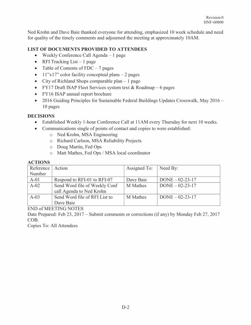
Revision 0 HNF-60800
D-2
Ned Krohn and Dave Baie thanked everyone for attending, emphasized 10 week schedule and need for quality of the timely comments and adjourned the meeting at approximately 10AM.
LIST OF DOCUMENTS PROVIDED TO ATTENDEES
· Weekly Conference Call Agenda – 1 page
· RFI Tracking List – 1 page
· Table of Contents of FDC – 7 pages
· 11”x17” color facility conceptual plans – 2 pages
· City of Richland Shops comparable plan – 1 page
· FY17 Draft ISAP Fleet Services system text & Roadmap – 6 pages
· FY16 ISAP annual report brochure
· 2016 Guiding Principles for Sustainable Federal Buildings Updates Crosswalk, May 2016 –
10 pages
DECISIONS
· Established Weekly 1-hour Conference Call at 11AM every Thursday for next 10 weeks.
· Communications single of points of contact and copies to were established:
o Ned Krohn, MSA Engineering
o Richard Carlson, MSA Reliability Projects
o Doug Martin, Fed Ops
o Matt Mathes, Fed Ops / MSA local coordinator
ACTIONS
Reference Number
Action Assigned To: Need By:
A-01 Respond to RFI-01 to RFI-07 Dave Baie DONE – 02-23-17
A-02 Send Word file of Weekly Conf call Agenda to Ned Krohn
M Mathes DONE – 02-23-17
A-03 Send Word file of RFI List to Dave Baie
M Mathes DONE – 02-23-17
END of MEETING NOTES Date Prepared: Feb 23, 2017 – Submit comments or corrections (if any) by Monday Feb 27, 2017 COB. Copies To: All Attendees

Revision 0 HNF-60800
Attachment E
Probable Costs of Baseline and New Consolidated Shop Scenario
E-i

Revision 0 HNF-60800
E-1
BASELINE SCENARIO – STATUS QUO
· The ten existing fleet facilities total 36,962 SF
· In addition, space in MO-414 for administrative offices would be maintained into the future.
The table below includes:
· Reliability projects (Example: L-810)
· Candidate reliability projects (L-XXX)
· Work activities (Z-190)
· Candidate work activities (Z-XXX)
Applicable MSA policy determines when a tracking number is assigned, based on completion of the required elements and signature approvals to define a project or activity.
The list below totals $9.0 million in identified immediate needs for existing facilities, in two categories on immediate needs for facilities and site deficiencies and substandard conditions:
· Projects & Activities validated in FY16 ISAP and RPIP process - $8 million
· Candidate Projects and Candidate Activities from FY17 Fleet FDC effort - $1 million
The format of the table below in columns from left to right includes:
· Short title
· Project description
· Risks if Not Performed
· Mission Need
· System (assigned responsible for project or activity delivery)
· Funding Fiscal Year

Rev
isio
n 0
H
NF
-60
800
E-2
TA
BL
E E
-1:
FL
EE
T C
AN
DID
AT
E P
RO
JE
CT
S &
AC
TIV
ITIE
S U
PG
RA
DE
LIS
T
D
esc
rip
tio
n
L –
XX
X –
Reliab
ilit
y P
roje
ct
Z-X
XX
– M
ain
ten
an
ce A
cti
vit
y
Sco
pe D
esc
rip
tio
n
Ris
ks
if
No
t P
erf
orm
ed
M
issio
n N
eed
S
ys
tem
C
os
t
Pro
jects
& A
cti
vit
ies
iden
tifi
ed
in
Fle
et
Serv
ices F
acilit
ies
Ma
ste
r P
lan
, H
NF
-6016
4, R
evis
ion
-0-:
L-8
10,
Insta
ll P
ain
t B
ooth
in
Ne
w F
acili
ty (
Was -
A
uto
bod
y P
ain
t B
ooth
R
epla
cem
ent)
Repla
ce
th
e F
leet
Main
ten
ance A
uto
bod
y P
ain
t B
ooth
in its
entire
ty,
to m
eet
Modern
ization
pro
ject
guid
ance
.
As p
art
of
the Inte
gra
ted
Safe
ty M
anag
em
ent
Sys
tem
(I
SM
S),
an
d th
e
En
viro
nm
enta
l Mana
gem
ent
Syste
m (
EM
S),
MS
A’s
E
nvi
ronm
enta
l Polic
y re
quires u
s t
o im
pro
ve
environm
enta
l perf
orm
ance,
pre
vent p
ollu
tio
n, m
inim
ize
waste
, a
nd c
onserv
e
resourc
es. A
dditio
nally
, IS
MS
req
uires t
he
ide
ntif
ication o
f ha
zard
s a
nd
the d
evelo
pm
ent
and
im
ple
menta
tion o
f ha
zard
contr
ols
. T
he f
ailu
re o
f th
e
curr
ent
bo
dy
pa
int
booth
exposes p
ers
on
ne
l an
d th
e
environm
ent
to h
aza
rds
specific
to p
ain
t pro
ducts
. T
his
situ
ation c
onflic
ts w
ith
the s
atisfa
cto
ry c
om
plia
nce
of
MS
A’s
IS
MS
an
d E
MS
polic
ies.
The e
xis
ting p
ain
t boo
th in
4722
C is
dete
riora
ted t
o th
e
poin
t of
failu
re a
nd is
an o
ld
wate
r se
para
tor
desig
n. T
his
cre
ate
s a
waste
str
eam
due
to th
e c
hem
icals
inhere
nt
in
pain
ting.
A n
ew
booth
is
alrea
dy
pro
cure
d b
ut
a n
ew
fa
cili
ty o
uts
ide
of
the 4
00
Are
a h
as n
ot
be
en locate
d.
Once a
facili
ty is b
uilt
of
locate
d, th
is n
ew
booth
will
re
quire
insta
llation
. T
he
environm
enta
l re
vie
ws a
re
com
ple
te a
s t
his
does n
ot
use w
ate
r but m
echanic
al
paper
ele
ments
wh
ich c
lea
n
the a
ir a
s it
move
s o
ut
of
the
booth
.
Facili
ties
$956
,00
0

Rev
isio
n 0
H
NF
-60
800
E-3
Desc
rip
tio
n
L –
XX
X –
Reliab
ilit
y P
roje
ct
Z-X
XX
– M
ain
ten
an
ce A
cti
vit
y
Sco
pe D
esc
rip
tio
n
Ris
ks
if
No
t P
erf
orm
ed
M
issio
n N
eed
S
ys
tem
C
os
t
L-7
72,
Ele
ctr
ica
l Vehic
le
Charg
ing S
tatio
n f
or
2266
E F
acili
ty
In F
Y11,
six
ele
ctr
ic v
ehic
le
charg
ing s
tations w
ere
pro
cure
d a
nd o
nly
tw
o w
ere
in
sta
lled a
t 24
90 G
arl
ick,
with t
he o
thers
sto
red in th
e
ware
ho
use
. K
uri
on
Eng
ineerin
g p
rovid
ed m
ulti
-sta
tion d
esig
ns f
or
vehic
le
charg
ing s
tations o
n-s
ite a
t 2266
E a
nd 2
75
0E
, an
d a
P
lant F
orc
es W
ork
Revi
ew
w
as c
onducte
d.
As p
art
of
ISM
S a
nd E
MS
, M
SA
’s E
nviro
nm
enta
l P
olic
y
requires u
s t
o im
pro
ve
environm
enta
l perf
orm
ances,
pre
vent p
ollu
tio
n, m
inim
ize
waste
, a
nd t
o c
onserv
e
resourc
es.
Unle
ss t
his
In
frastr
uctu
re is
put
in p
lace,
Fle
et
Serv
ices w
ill b
e f
ar
less
able
to m
ove
to
ward
s a
lo
wer
em
issio
n,
more
fuel
eff
icie
nt
vehic
le f
leet.
This
w
ill a
lso c
ause d
ifficulti
es in
re
main
ing c
om
plia
nt
with
EM
S a
nd c
ause p
ossib
le
loss o
f P
erf
orm
ances
Incentive (
PI)
as w
ell.
The in
sta
llatio
n o
f on
-site
ele
ctr
ic v
ehic
le c
harg
ing
sta
tion is
need
ed in t
he 2
00
A
reas in o
rder
to s
upport
site
susta
ina
bili
ty g
oa
ls.
This
in
sta
llatio
n w
ill a
llow
th
e
wid
espre
ad u
se o
f th
e
Nis
san L
eaf
in t
he M
SA
fle
et
and w
ou
ld s
up
port
futu
re u
se
of
ele
ctr
ic v
eh
icle
s o
n th
e
Hanfo
rd S
ite.
Facili
ties
$414
,00
0

Rev
isio
n 0
H
NF
-60
800
E-4
Desc
rip
tio
n
L –
XX
X –
Reliab
ilit
y P
roje
ct
Z-X
XX
– M
ain
ten
an
ce A
cti
vit
y
Sco
pe D
esc
rip
tio
n
Ris
ks
if
No
t P
erf
orm
ed
M
issio
n N
eed
S
ys
tem
C
os
t
L-8
11,
27
11E
A &
273
E
Fire B
arr
ier
Weld
ing
Are
as
Insta
ll she
et m
eta
l in b
oth
th
e 2
711
EB
an
d 2
73
E
Build
ings. T
he s
heet m
eta
l w
ill p
rovid
e p
rote
ction
fro
m
fire
in th
ese a
reas f
rom
w
eld
ing, gri
nd
ing
an
d o
ther
hot
work
activ
itie
s
The a
dditio
n o
f th
ese
fire
barr
iers
for
weld
ing a
nd h
ot
work
activ
itie
s w
ould
rem
ove
th
e n
eed
for
fire
wa
tch
pers
onn
el.
Und
er
our
curr
ent
conditio
ns,
a s
econ
d p
ers
on
is r
equ
ired t
o s
up
port
hot
work
activ
itie
s t
o m
eet
Hanfo
rd s
ite f
ire c
ode.
This
doub
les t
he c
ost
to th
e job
curr
ently
be
ing p
erf
orm
ed
and r
em
ove
s p
ers
onne
l fro
m
oth
er
job a
ssig
nm
ents
. W
ith
reductio
ns in p
ers
onne
l, support
for
fire
watc
h is n
ot
alw
ays
ava
ilab
le.
Fle
et
main
tena
nce p
rovi
de
s
a f
ull
sp
ectr
um
of
vehic
le a
nd
equ
ipm
ent
main
tena
nce f
or
Hanfo
rd’s
ve
hic
le a
nd
equ
ipm
ent
fleet
sup
port
ing
the c
lean
up p
roje
cts
. A
num
ber
of
the m
ain
tena
nce
serv
ices p
rovi
ded
inclu
de t
he
need
to p
erf
orm
hot
work
(w
eld
ing
, gri
nd
ing,
cuttin
g,
etc
.) B
eca
use o
f th
e lack o
f adeq
uate
fire r
ate
d b
arr
iers
w
ith
in t
he F
lee
t M
ain
ten
ance
facili
ty,
the p
erf
orm
ance o
f hot
work
activ
itie
s r
eq
uires
the u
se
of
a f
ire w
atc
h.
Constr
uction o
f fire
rate
d
barr
iers
can a
llow
for
the u
se
of
a f
ire w
atc
h. C
onstr
uctio
n
of
fire
rate
d b
arr
iers
can
allo
w f
or
the e
limin
ation o
f th
e f
ire w
atc
h w
hile
pro
vid
ing
an e
quiv
ale
nt le
vel of
fire
safe
ty.
This
chang
e r
ed
uce
s
veh
icle
main
tena
nce c
osts
w
hile
als
o incre
asin
g
resourc
e f
lexib
ility
within
F
leet
by
allo
win
g th
e f
ire
watc
h e
mplo
yee t
o c
on
duct
oth
er
reve
nue g
en
era
ting
work
.
Facili
ties
$293
,00
0

Rev
isio
n 0
H
NF
-60
800
E-5
Desc
rip
tio
n
L –
XX
X –
Reliab
ilit
y P
roje
ct
Z-X
XX
– M
ain
ten
an
ce A
cti
vit
y
Sco
pe D
esc
rip
tio
n
Ris
ks
if
No
t P
erf
orm
ed
M
issio
n N
eed
S
ys
tem
C
os
t
L-8
13,
Concre
te P
ads -
211
ED
and 2
12
ED
Tents
F
leet
Ma
inte
na
nce h
as t
wo
tents
locate
d in th
e 2
711
E
Park
ing L
ot .
The t
ents
pro
vid
e a
dditio
nal s
pace to
perf
orm
equip
ment
repa
ir
and m
ain
tenance
. T
ents
, 211
ED
and 2
12
ED
are
60
fo
ot
lon
g a
nd 3
0 f
eet
wid
e.
Curr
ently
the f
loor
un
der
the
tent
is h
alf c
oncre
te a
nd h
alf
gra
vel. T
he e
xis
ting c
oncre
te
pad is b
elo
w g
rad
e a
llow
ing
rain
wate
r to
po
ol in
sid
e
tents
. T
he t
wo
ne
w c
oncre
te
pads w
ill b
e 4
0 f
oot
wid
e,
80
feet
lon
g, a
nd 8
inches t
hic
k.
The t
ents
will
ne
ed t
o b
e
dis
assem
ble
d f
rom
their
exis
ting location a
nd m
ove
d
to th
e n
ew
concre
te p
ads.
Continu
e to u
se te
nts
th
at
leak r
ain
wate
r, c
rea
ting a
slip
pin
g h
aza
rd f
or
the
mechanic
s/o
ilers
. H
avin
g t
o
work
in g
ravel are
as t
hat
require
the
mechanic
s/o
iler
to c
raw
l on t
he
ir h
an
ds a
nd
knees c
an c
ause in
juri
es.
Fle
et
Ma
inte
na
nce p
rovi
de
s
cra
ne m
ain
tena
nce to
th
e
Hanfo
rd C
ran
e a
nd R
igg
ing
org
an
ization.
These c
ran
es
support
man
y h
igh p
riority
cle
an
up p
roje
cts
. A
majo
rity
of
the m
ain
ten
ance is
com
ple
ted in t
wo
larg
e t
ents
on t
he c
entr
al pla
tea
u.
These
two te
nts
ne
ed c
oncre
te
pads t
o e
limin
ate
flo
odin
g
that
occurs
due to
rain
wate
r and s
no
w m
elt
com
ing in
under
the e
dg
es a
nd s
ett
ling
insid
e th
e te
nt are
a a
s t
he
y w
ill b
e r
ais
ed 4
-6”
abo
ve
gra
de.
Ad
ditio
nally
, it
will
pro
vid
e a
sig
nific
an
tly
impro
ved w
alk
ing a
nd
work
ing s
urf
ace. T
hese ten
ts
will
contin
ue s
up
port
ing
cra
ne a
nd h
ea
vy/
larg
e
equ
ipm
ent
main
tena
nce,
thus r
equ
irin
g t
his
in
vestm
ent.
Facili
ties
$181
,00
0

Rev
isio
n 0
H
NF
-60
800
E-6
Desc
rip
tio
n
L –
XX
X –
Reliab
ilit
y P
roje
ct
Z-X
XX
– M
ain
ten
an
ce A
cti
vit
y
Sco
pe D
esc
rip
tio
n
Ris
ks
if
No
t P
erf
orm
ed
M
issio
n N
eed
S
ys
tem
C
os
t
L-7
73,
Ele
ctr
ica
l V
ehic
le
Charg
ing S
tatio
n f
or
2750
E F
acili
ty
The in
sta
llatio
n o
f an o
n-s
ite
ele
ctr
ic v
ehic
le c
harg
ing
sta
tion is
need
ed in t
he 2
00
A
reas,
in o
rder
to s
upport
site
susta
ina
bili
ty g
oa
ls.
This
in
sta
llatio
n w
ill a
llow
th
e
wid
espre
ad u
se o
f th
e
Nis
san L
eaf
in t
he M
SA
fle
et
and w
ou
ld s
up
port
futu
re u
se
of
ele
ctr
ic v
eh
icle
s o
n th
e
Hanfo
rd S
ite.
As p
art
of
ISM
S a
nd E
MS
, M
SA
’s E
nviro
nm
enta
l P
olic
y
requires u
s t
o im
pro
ve
environm
enta
l perf
orm
ance,
pre
vent p
ollu
tio
n, m
inim
ize
waste
, a
nd t
o c
onserv
e
resourc
es.
Unle
ss t
his
in
frastr
uctu
re is
put in
pla
ce
, fleet
serv
ices w
ill b
e f
ar
less
able
to m
ove
to
ward
s a
lo
wer
em
issio
n,
more
fuel
eff
icie
nt
vehic
le f
leet.
This
w
ill a
lso c
ause d
ifficulti
es in
re
main
ing c
om
plia
nt
with t
he
EM
S a
nd c
ause p
ossib
le
loss o
f P
I as w
ell.
The in
sta
llatio
n o
f an o
n-s
ite
ele
ctr
ic v
ehic
le c
harg
ing
sta
tion is
need
ed in t
he 2
00
A
reas in o
rder
to s
upport
site
susta
ina
bili
ty g
oa
ls.
This
in
sta
llatio
n w
ill a
llow
th
e
wid
espre
ad u
se o
f th
e
Nis
san L
eaf
in t
he M
SA
fle
et
and w
ou
ld s
up
port
futu
re u
se
of
ele
ctr
ic v
eh
icle
s o
n th
e
Hanfo
rd S
ite.
Facili
ties
$392
,00
0

Rev
isio
n 0
H
NF
-60
800
E-7
Desc
rip
tio
n
L –
XX
X –
Reliab
ilit
y P
roje
ct
Z-X
XX
– M
ain
ten
an
ce A
cti
vit
y
Sco
pe D
esc
rip
tio
n
Ris
ks
if
No
t P
erf
orm
ed
M
issio
n N
eed
S
ys
tem
C
os
t
L-8
45,
Ne
w F
lee
t M
ain
ten
ance B
uild
ing
(Repla
ces L
-746
& L
-74
7)
Constr
uct
ne
w 1
2,0
00 f
t2
Fle
et
Ma
inte
na
nce f
acili
ty a
t 4
th a
nd B
altim
ore
. T
he f
acili
ty
will
pro
vid
e a
de
qua
te f
loor
space f
or
all
light
eq
uip
men
t m
ain
tenance.
Once th
is
pro
ject
is c
om
ple
te,
pro
ject
L-8
10 t
o r
elo
cate
the
bo
dy
shop a
nd p
ain
ting o
pera
tio
n
from
the 4
00 a
rea t
o th
e 2
73
E f
acili
ty c
an b
e
imple
mente
d.
Com
ple
tion o
f th
ese t
wo p
roje
cts
will
allo
w
fleet
to f
ully
vacate
the 4
00
are
a a
nd h
ave
a
consolid
ate
d o
pera
tio
n o
n
the p
late
au
in s
upp
ort
of
the
RL v
i sio
n.
Fle
et
serv
ices w
ill c
on
tinue
to u
se ina
deq
uate
400 a
rea
fa
cili
ties.
MS
A F
leet
Serv
ices p
rovid
es
critic
al m
ain
tenance s
erv
ice
to a
sig
nific
ant
port
ion o
f th
e
entir
e H
anfo
rd f
leet,
in
clu
din
g e
merg
ency
an
d
security
ve
hic
les/e
quip
men
t.
The lo
cation o
f th
e 2
711
E
Fle
et
Ma
inte
na
nce is
als
o
critic
al t
o th
e F
Y20
15 V
isio
n
and t
he f
utu
re s
upp
ort
of
WT
P.
If F
leet S
erv
ices
cannot
pro
vid
e s
afe
an
d
eff
icie
nt
serv
ices d
ue t
o lack
of
shop s
pace, th
e r
esu
lts
could
be c
ata
str
oph
ic.
OH
C
mile
sto
nes a
nd P
Is c
ould
be
thre
ate
ne
d, a
nd t
his
rais
es
the c
oncern
th
at som
e
custo
mers
ma
y co
ntinue t
o
use a
veh
icle
or
pie
ce o
f equ
ipm
ent
that
is in n
eed o
f serv
ice,
incre
asin
g s
afe
ty
risks.
Lack o
f suff
icie
nt
space a
lso
puts
Fle
et
Serv
ices m
ain
ten
ance
pers
onn
el in
pre
cario
us
situ
ations.
Ma
inte
na
nce o
f th
e e
xis
ting f
acili
ties is
becom
ing a
fin
ancia
l burd
en
whic
h incre
ases r
ate
s t
o a
ll users
of
Fle
et
Serv
ices.
Facili
ties
$3,8
85,0
00

Rev
isio
n 0
H
NF
-60
800
E-8
Z-1
82, 2
711
E S
torm
w
ate
r C
om
plia
nce
(R
etit
led t
o: C
onso
lidate
d
Com
ple
x N
PD
ES
Sto
rm
wate
r C
om
plia
nce,
de
lete
all
refe
rences t
o 2
711
E
and 2
71
1)
The C
lea
n W
ate
r A
ct
imple
mente
d b
y N
ation
al
Pollu
tio
n D
ischarg
e
Elim
inatio
n S
yste
m
(NP
DE
S)C
onstr
uctio
n
Activi
ty a
nd I
ndustr
ial A
ctivity
pro
gra
ms p
reve
nt
enrich
ed
sto
rm w
ate
r in
filtr
ation
directly
to g
round
wate
r w
ith
out
best
pra
ctices o
r tr
eatm
ent
to m
eet
nation
al,
sta
te a
nd s
ite c
leanu
p
obje
ctive
s.
The e
xis
ting 2
711
fleet
com
ple
x in
clu
des
appro
xim
ate
ly 3
0 a
cre
s o
f gra
vel a
reas w
ith s
om
e
limite
d p
ort
ions o
f pa
ved
are
as t
ha
t are
po
llutio
n
genera
ting s
urf
aces u
sed
daily
by
fleet
vehic
les a
nd
equ
ipm
ent.
The N
PD
ES
sta
ndard
s f
or
sto
rm w
ate
r quan
tity
and w
ate
r qua
lity
are
not
fully
met.
Com
pro
mis
ed f
leet
layd
ow
n
are
as e
xperi
ence p
eri
od
ic
sedim
ent
laden s
tand
ing
w
ate
r fo
r 10 t
o 1
4 d
ays
a
year.
If t
he p
roje
ct
is n
ot
undert
aken,
the q
ua
ntity
of
runoff
and q
ualit
y of
runoff
th
at
poo
ls in
layd
ow
n y
ard
are
as w
ill lim
it fleet
opera
tio
ns.
Se
dim
ent
lade
n
surf
ace w
ate
r w
ill m
igra
te
into
gro
und
wate
r are
as
with
out
tre
atm
ent,
ad
din
g
meta
ls p
lus o
ther
trace
ele
ments
cate
gori
zed a
s
non-p
oin
t so
urc
e loa
din
g.
With
out N
PD
ES
com
plia
nce,
the 2
711
com
ple
x y
ard
are
as
are
un
ab
le t
o f
ully
meet
DO
E
RL o
bje
ctives f
or
com
plia
nt
opera
tio
ns f
or
rem
ain
ing
serv
ice life a
nd t
he R
L V
isio
n
by
FY
20
28 a
s w
ell
as W
TP
and D
FLA
W P
rogra
m n
eeds
thro
ug
h F
Y206
0.
The 2
711 E
/EA
/EB
/ED
com
ple
x w
ith 2
11E
D a
nd
212
ED
aft
er
pro
ject
L-8
45
will
have a
forw
ard
serv
ice
life o
f at
least
26 r
em
ain
ing
years
to
FY
2043
for
2711
. T
he m
ain
be
nefit
of
NP
DE
S
com
plia
nce is
red
uced lo
ad
s
of
enriched s
urf
ace r
unoff
fr
om
pollu
tion g
en
era
ting
surf
aces r
eachin
g
gro
un
dw
ate
r. A
com
pre
hensiv
e r
evie
w o
f sto
rm w
ate
r cond
itions f
rom
w
est
sid
e o
f M
O-4
14 t
o w
est
sid
e o
f 27
11 c
om
ple
x y
ard
, nort
h o
f 4th
Str
eet
for
the
next
26
ye
ars
of
serv
ice. T
he
stu
dy
will
de
velo
p a
pla
n f
or
allo
cating o
utd
oor
sto
rage f
or
fle
et ne
eds u
nder
roof
on
cove
red
pa
ved s
urf
ace, op
en
to s
ky
paved s
urf
aces,
and
open
to s
ky
gra
vel surf
aces
to m
eet
NP
DE
S c
om
plia
nce.
Gra
vel an
d p
aved la
ydo
wn
yard
s w
ere
pla
ced d
uri
ng
1984
to 1
99
7 p
lus
incre
menta
l cha
nges.
The
gra
vel s
urf
ace f
leet
layd
ow
n
yard
s a
re c
om
pro
mis
ed b
y ve
hic
le a
nd e
quip
ment
travel
while
pond
ed w
ate
r is
sta
ndin
g.
Ad
ded
enri
chm
ent
from
untr
eate
d r
unoff
in y
ard
are
as b
y fleet
op
era
tions
would
be a
void
ed. N
PD
ES
sto
rm w
ate
r best
pra
ctic
es
will
be r
ecom
mended a
nd
imple
mente
d,
base
d o
n t
he
com
pre
hensiv
e a
na
lysis
Fle
et
Site
$200
,00
0

Rev
isio
n 0
H
NF
-60
800
E-9
Desc
rip
tio
n
L –
XX
X –
Reliab
ilit
y P
roje
ct
Z-X
XX
– M
ain
ten
an
ce A
cti
vit
y
Sco
pe D
esc
rip
tio
n
Ris
ks
if
No
t P
erf
orm
ed
M
issio
n N
eed
S
ys
tem
C
os
t
inclu
din
g s
urv
eyi
ng a
nd c
ivil
eng
ine
erin
g tasks,
plu
s s
ite
constr
uctio
n -
add
pip
e,
upgra
de c
atc
h b
asin
, a
nd
add n
ew
dry
well.

Rev
isio
n 0
H
NF
-60
800
E-1
0
Z-X
XX
, 273E
NP
DE
S
Sto
rm w
ate
r C
om
plia
nce
T
he C
lea
n W
ate
r A
ct
imple
mente
d b
y N
ation
al
Pollu
tio
n D
ischarg
e
Elim
inatio
n S
yste
m (
NP
DE
S)
Constr
uction A
ctivi
ty a
nd
Industr
ial A
ctivi
ty p
rogra
ms
pre
vent e
nriche
d s
torm
wate
r in
filtr
atio
n d
irectly
to
gro
un
dw
ate
r w
ithou
t best
pra
ctic
es o
r tr
ea
tment
to
meet
natio
nal, s
tate
an
d s
ite
cle
an
up o
bje
ctive
s.
The
exis
ting 2
73E
fle
et
com
ple
x
inclu
des a
ppro
xim
ate
ly 3
0
acre
s o
f gra
vel a
reas w
ith
som
e li
mite
d p
ort
ions o
f paved a
reas t
hat are
pollu
tion
ge
nera
ting
surf
aces
used d
aily
by
fleet
vehic
les
and e
qu
ipm
ent.
The N
PD
ES
sta
ndard
s f
or
sto
rm w
ate
r quan
tity
and
wate
r qua
lity
are
not
fully
met.
Com
pro
mis
ed f
leet
layd
ow
n
are
as e
xperi
ence p
eri
od
ic
sedim
ent
laden s
tand
ing
w
ate
r fo
r 10 t
o 1
4 d
ays
a
year.
If t
he p
roje
ct
is n
ot
undert
aken,
the q
ua
ntity
of
runoff
and q
ualit
y of
runoff
th
at
poo
ls in
layd
ow
n y
ard
are
as w
ill lim
it fleet
opera
tio
ns.
Se
dim
ent
lade
n
surf
ace w
ate
r w
ill m
igra
te
into
gro
und
wate
r are
as
with
out
tre
atm
ent,
ad
din
g
meta
ls p
lus o
ther
trace
ele
ments
cate
gori
zed a
s
non-p
oin
t sourc
e loa
din
g.
With
out N
PD
ES
com
plia
nce,
the 2
73
E c
om
ple
x y
ard
are
as a
re u
na
ble
to f
ully
m
eet
DO
E R
L o
bje
ctiv
es f
or
com
plia
nt o
pera
tions f
or
rem
ain
ing s
erv
ice life a
nd
the R
L V
isio
n b
y F
Y20
28 a
s
well
as W
TP
and D
FLA
W
Pro
gra
m n
eeds t
hro
ug
h
FY
20
60.
The 2
73E
aft
er
pro
ject
L-8
45
will
have a
forw
ard
serv
ice
life o
f at
least
26 r
em
ain
ing
years
to
FY
2043
for
273
E.
The m
ain
be
nefit
of
NP
DE
S
com
plia
nce is
red
uced lo
ad
s
of
enriched s
urf
ace r
unoff
fr
om
pollu
tion g
en
era
ting
surf
aces r
eachin
g
gro
un
dw
ate
r. A
com
pre
hensiv
e r
evie
w o
f sto
rm w
ate
r cond
itions w
est
and s
urr
ou
nd
ing t
he
27
3E
str
uctu
re s
outh
of
4th
Str
ee
t fo
r th
e n
ext
26 y
ears
of
serv
ice. T
he s
tud
y w
ill
develo
p a
pla
n f
or
allo
ca
ting
outd
oor
sto
rag
e f
or
fleet
needs u
nd
er
roof
on c
ove
red
paved s
urf
ace, o
pen t
o s
ky
paved s
urf
aces,
an
d o
pen t
o
sky
gra
vel s
urf
aces t
o m
eet
NP
DE
S c
om
plia
nce. G
rave
l and p
ave
d la
ydo
wn y
ard
s
were
pla
ced
duri
ng 1
98
4 to
1997
plu
s in
cre
menta
l changes.
The g
ravel s
urf
ace
fleet
layd
ow
n y
ard
s a
re
com
pro
mis
ed b
y vehic
le a
nd
equ
ipm
ent
travel w
hile
pond
ed w
ate
r is
sta
nd
ing.
Add
ed e
nrichm
ent
from
untr
eate
d r
unoff
in y
ard
are
as b
y fleet
op
era
tions
would
be a
void
ed. N
PD
ES
sto
rm w
ate
r best
pra
ctic
es
will
be r
ecom
mended a
nd
imple
mente
d,
base
d o
n t
he
com
pre
hensiv
e a
na
lysis
in
clu
din
g s
urv
eyi
ng a
nd c
ivil
eng
ine
erin
g tasks,
plu
s s
ite
Fle
et
Site
$200
,00
0

Rev
isio
n 0
H
NF
-60
800
E-1
1
Desc
rip
tio
n
L –
XX
X –
Reliab
ilit
y P
roje
ct
Z-X
XX
– M
ain
ten
an
ce A
cti
vit
y
Sco
pe D
esc
rip
tio
n
Ris
ks
if
No
t P
erf
orm
ed
M
issio
n N
eed
S
ys
tem
C
os
t
constr
uctio
n -
add
pip
e,
upgra
de c
atc
h b
asin
s,
etc
. Z
-179, 2
711
Ele
ctr
ica
l U
pgra
des
Ele
ctr
ical upgra
des in 2
711
str
uctu
res a
nd s
erv
ice t
o 2
11
and 2
12 s
tructu
res t
o
support
the a
rra
y of
app
liances a
nd to
ols
re
quire
d to
perf
orm
work
re
lative to e
xis
ting s
tructu
re
ele
ctr
ica
l sys
tem
, re
quirin
g 1
ne
w t
ransfo
rmer,
work
on 2
pole
s,
13.8
kV
ris
er,
feeder
line a
nd 4
ne
w p
ane
ls.
If t
he p
roje
ct
is n
ot
undert
aken,
work
pla
ce
safe
ty is
at
risk for
ove
rloa
ded
ele
ctr
ical circuits.
With
out N
EC
an
d I
BC
cod
e
com
plia
nce, th
e 2
711
com
ple
x a
re u
nab
le t
o s
afe
ly
and f
ully
meet
DO
E R
L
obje
ctive
s f
or
com
plia
nt
opera
tio
ns f
or
rem
ain
ing
serv
ice life a
nd t
he R
L V
isio
n
by
FY
20
28 a
s w
ell
as W
TP
and D
FLA
W P
rogra
m n
eeds
thro
ug
h F
Y206
0.
The m
ain
ne
ed is f
or
adde
d
pane
l cap
acity
for
the
num
ber
of
outle
ts in 2
71
1
work
ba
y are
as f
or
work
er
safe
ty t
o a
void
ove
rload
ing
exis
ting c
ircuits
. T
he s
ho
p
facili
ty is
use
d m
ore
hea
vily
th
an it
was o
rigin
ally
desig
ned f
or
port
ab
le t
oo
ls
that
plu
g into
outlets
for
dia
gnostic a
nd
report
un
its.
Facili
ties
$571
,01
1

Rev
isio
n 0
H
NF
-60
800
E-1
2
Desc
rip
tio
n
L –
XX
X –
Reliab
ilit
y P
roje
ct
Z-X
XX
– M
ain
ten
an
ce A
cti
vit
y
Sco
pe D
esc
rip
tio
n
Ris
ks
if
No
t P
erf
orm
ed
M
issio
n N
eed
S
ys
tem
C
os
t
L-X
XX
, 273E
Sto
rage
Facili
ty
The 2
73E
shop h
as 4
ba
ys in
1 p
erm
anent
sto
rage
str
uctu
re p
lus 4
Co
nex
sto
rage u
nits
, to
meet
part
s
and e
qu
ipm
ent
supp
ly
sto
rage n
ee
ds. W
ith the
exis
ting c
onfigura
tion,
housekeepin
g a
nd e
ffic
iency
obje
ctive
s f
or
the 2
73
E
facili
ty a
re n
ot
fully
met.
Pro
ject
L-8
45 w
ill c
on
vert
2
work
ba
ys t
he 2
73
E t
o a
uto
bod
y a
nd p
ain
t fu
nctio
ns
aft
er
4722C
is n
o long
er
used.
Ove
rcro
wdin
g w
ithin
th
e 2
73
E s
ho
p 1
0 w
ork
ba
ys
requires a
4 b
ay
perm
anent
sto
rage s
olu
tion
identical to
1
exis
ting s
tora
ge b
uild
ing
west
of
273
E t
o a
void
housekeepin
g p
roble
ms
typ
ically
associa
ted w
ith
4
Conex s
tora
ge u
nits s
outh
of
273
E.
If t
he p
roje
ct
is n
ot
undert
aken f
or
addin
g
perm
anent
sto
rag
e u
nit
str
uctu
re,
the
27
3E
ma
y le
ss
eff
icie
ntly
function
wh
ile
meetin
g D
OE
RL o
bje
ctive
s
for
work
pla
ce s
afe
ty,
eff
icie
ncy
to s
erv
ice f
leet a
nd
housekeepin
g f
or
rem
ain
ing
serv
ice life.
The 2
73E
has a
pro
jecte
d
serv
ice life o
f 26 +
rem
ain
ing
years
to
FY
2043
. T
he
benefits
of
ad
din
g p
erm
anent
sto
rage s
tructu
re t
o r
epla
ce
C
onex b
ox u
nits
inclu
des
bett
er
ventila
tio
n a
nd
insula
tion w
he
n w
ork
ers
access t
he u
nits
, p
lus
avo
ided h
ousekeepin
g.
Th
e
main
str
uctu
re 2
73
E w
ill b
e
in u
se
, so th
e th
is p
roje
ct
is
scoped t
o a
ddre
ss b
uild
ing
envelo
pe n
ee
ds f
or
tota
l sto
rage n
ee
ds f
or
fleet
inclu
din
g 2
73
E t
he n
ext
26 +
ye
ars
of
serv
ice.
Facili
ties
$600
,00
0

Rev
isio
n 0
H
NF
-60
800
E-1
3
Desc
rip
tio
n
L –
XX
X –
Reliab
ilit
y P
roje
ct
Z-X
XX
– M
ain
ten
an
ce A
cti
vit
y
Sco
pe D
esc
rip
tio
n
Ris
ks
if
No
t P
erf
orm
ed
M
issio
n N
eed
S
ys
tem
C
os
t
Z-X
XX
, 2711 I
nsula
tion
Repla
cem
ent
The I
nte
rnatio
nal B
uild
ing
Code,
Nation
al E
lectr
ica
l C
ode p
lus W
A S
tate
supple
ments
to I
BC
and
N
EC
re
quir
es in
su
lation
perf
orm
ance to m
eet
nationa
l, sta
te o
bje
ctive
s f
or
energ
y conse
rvatio
n. W
ith
the e
xis
ting w
all
insu
latio
n
com
pro
mis
ed,
the
ap
plic
able
build
ing c
odes a
re n
ot
fully
m
et. E
xecutiv
e O
rder
1369
3
requirem
ents
, p
lus
app
licab
le s
ectio
ns o
f 1343
2
and 1
35
14 s
et sta
nd
ard
s f
or
build
ing e
nve
lop
e
perf
orm
ance in
energ
y conserv
atio
n.
The
com
pro
mis
ed w
all
insula
tio
n
is a
n o
pp
ort
un
ity
for
repla
cem
ent
for
exte
nd
ing
serv
ice life o
f th
e f
acili
ty,
resto
ring b
uild
ing c
od
e
com
plia
nce, b
y cha
ng
ing
exis
ting r
oll
insula
tion t
o r
igid
in
sula
tion w
ith
R-3
5 r
ating,
or
bett
er.
If t
he p
roje
ct
is n
ot
undert
aken,
the insu
lation
w
ill c
ontin
ue t
o f
lake o
ff in
to
work
are
as a
nd th
e b
uild
ing
ele
ctr
ica
l energ
y consum
ptio
n w
ill in
cre
ase.
With
out th
e insula
tion
repla
cem
ent,
th
e 2
711 E
/
EA
/ E
B c
om
ple
x w
ill b
e
unab
le t
o m
eet
DO
E R
L
obje
ctive
s f
or
build
ing
lo
nge
vity
, re
main
ing s
erv
ice
life o
r o
pera
ting
costs
.
The 2
711 E
/ E
A /
EB
has a
pro
jecte
d s
erv
ice life o
f 26
rem
ain
ing y
ears
to F
Y202
42
or
FY
20
43.
The b
en
efits
of
add
ing r
igid
insula
tion t
o
repla
ce c
om
pro
mis
ed
exis
ting r
oll
typ
e insu
latio
n
with a
lo
wer
desig
n R
va
lue
in
clu
de a
nn
ua
l en
erg
y savi
ngs a
nd r
ed
uced loa
ds
on H
VA
C s
yste
m.
The t
wo
HV
AC
un
its s
erv
ing th
e m
ain
str
uctu
re w
ill b
e c
ha
ng
ed o
ut
durin
g F
Y201
6 o
r F
Y20
17,
so the t
his
pro
ject
is s
cope
d
to a
ddre
ss b
uild
ing e
nve
lop
e
needs f
or
the
next
26 y
ears
of
serv
ice, in
clu
din
g s
ea
ling
pene
trations a
nd a
t ro
ll -up
doors
. O
rig
ina
l in
su
lation
mate
rial s
urf
ace p
lace
d in
1984
, 19
91 a
nd 1
997 is
be
yond
warr
anty
and
com
pro
mis
ed f
rom
agin
g,
mois
ture
contr
ol,
condensa
tion, h
eat
an
d th
aw
cyc
les.
Facili
ties
$200
,00
0

Rev
isio
n 0
H
NF
-60
800
E-1
4
Desc
rip
tio
n
L –
XX
X –
Reliab
ilit
y P
roje
ct
Z-X
XX
– M
ain
ten
an
ce A
cti
vit
y
Sco
pe D
esc
rip
tio
n
Ris
ks
if
No
t P
erf
orm
ed
M
issio
n N
eed
S
ys
tem
C
os
t
L-X
XX
, 2711
E C
om
ple
x
Sto
rage F
acili
ty (
Revis
ed
title
: C
onsolid
ate
d
Com
ple
x S
tora
ge,
dele
te
refe
rences t
o 2
711
E a
nd
2711)
The 2
711 s
hop c
om
ple
x h
as
limite
d p
erm
anent
sto
rag
e
with
in t
he 2
71
1 e
xis
ting
str
uctu
res p
lus t
em
pora
ry
sto
rage in 1
0 C
onex s
tora
ge
units
, to
meet
kitt
ed a
nd
sta
ged p
art
s f
or
equ
ipm
ent
supply
sto
rage n
ee
ds. W
ith
the e
xis
ting c
onfigura
tion,
housekeepin
g a
nd e
ffic
iency
obje
ctive
s f
or
the 2
71
1
facili
ty a
re n
ot
fully
met. T
o
elim
inate
ove
rcro
wd
ing
with
in t
he 2
71
1 s
ho
p w
ork
ba
ys r
equ
ires a
10 b
ay
perm
anent
sto
rag
e s
olu
tion
sim
ilar
to 1
exis
ting s
tora
ge
build
ing w
est
of
27
3E
B
uild
ing (
4 b
ay
siz
e)
to a
void
housekeepin
g p
roble
ms
typ
ically
associa
ted w
ith
10
C
onex s
tora
ge u
nits
south
west
of
2711
.
If t
he p
roje
ct
is n
ot
undert
aken f
or
addin
g
perm
anent
sto
rag
e u
nit
str
uctu
re,
the
27
11 m
ay
less
eff
icie
ntly
function
wh
ile
meetin
g D
OE
RL o
bje
ctive
s
for
work
pla
ce s
afe
ty,
eff
icie
ncy
to s
erv
ice f
leet a
nd
housekeepin
g f
or
rem
ain
ing
serv
ice life.
The 2
711 c
om
ple
x h
as a
pro
jecte
d s
erv
ice life o
f 26
rem
ain
ing y
ears
to F
Y204
3.
The b
enefits
of
ad
din
g
perm
anent
sto
rag
e s
tructu
re
to r
ep
lace C
onex b
ox u
nits
in
clu
des b
etter
ventila
tion
and insu
lation w
he
n w
ork
ers
access t
he u
nits
, p
lus
avo
ided h
ousekeepin
g.
Th
e
main
str
uctu
re 2
73
E w
ill b
e
in u
se
, so th
e th
is p
roje
ct
is
scoped t
o a
ddre
ss b
uild
ing
envelo
pe n
ee
ds f
or
tota
l sto
rage n
ee
ds f
or
fleet
inclu
din
g 2
73
E t
he n
ext
26 +
ye
ars
of
serv
ice.
Facili
ties
$600
,00
0
The y
ear
need
ed f
or
all
ab
ove p
roje
cts
and m
ain
tenance
activ
itie
s is
FY
20
17,
or
as s
oon t
here
aft
er
as f
undin
g is
ava
ilab
le.
Tota
l Estim
ate
d C
ost
= $
7,9
92,0
11
Roun
d to:
$8 m
illio
n

Rev
isio
n 0
H
NF
-60
800
E-1
5
Desc
rip
tio
n
L –
XX
X –
Reliab
ilit
y P
roje
ct
Z-X
XX
– M
ain
ten
an
ce A
cti
vit
y
Sco
pe D
esc
rip
tio
n
Ris
ks
if
No
t P
erf
orm
ed
M
issio
n N
eed
S
ys
tem
C
os
t
Un
met
Need
s f
or
Can
did
ate
pro
jects
& A
cti
vit
ies
Id
en
tifi
ed
du
rin
g F
leet
FD
C E
ffo
rt i
n F
Y201
7:
Z-1
82, 2
711
Dry
Well
Corr
ecte
d o
ne p
art
of
the
exis
ting s
ubsta
ndard
dra
inage
cond
ition a
t 2
711
com
ple
x f
or
wa
ter
quantity
hand
ling.
Com
ple
ted r
ece
ntly.
C
om
ple
ted r
ece
ntly.
Fle
et
$7
0,5
70
L-7
97,
HV
AC
R
epla
cem
ent
in a
ll F
leet
Facili
ties*
2711
Hea
t P
um
p R
epla
ce
is
part
of
L-7
97 a
t $13
3,4
90
. T
he r
epla
cem
ent
for
273
E is
not
inclu
ded
.
Health a
nd s
afe
ty is
at
risk
alo
ng w
ith h
igher
energ
y consum
ptio
n in h
ot
an
d c
old
tim
es o
f th
e y
ear.
See a
bo
ve.
Fle
et
$1
33
,49
0*
Z-1
60,
Pit
fill-
in in 2
711
Pits
in 2
711
are
of
substa
nd
ard
heig
ht. T
he
pro
posa
l fill
s in
1 o
f 2 tru
ck
len
gth
pits
for
a s
mooth
wo
rk
ba
y floor.
Reduces lia
bili
ty f
or
safe
ty
incid
ents
to tri
p o
ver
rais
ed
ste
el edg
e, or
work
forc
e
hea
lth c
laim
s d
ue
ina
deq
uate
he
ad h
eig
ht
in
pit.
See a
bo
ve.
Fle
et
$1
02
,27
3
L-8
14,
Insula
tion R
ep
air
in
2711
S
ee a
bo
ve f
or
insula
tion
repair.
This
pro
posa
l is f
or
full
rep
lacem
ent,
not
repa
ir.
Health a
nd s
afe
ty is
at
risk
alo
ng w
ith h
igher
energ
y consum
ptio
n in h
ot
an
d c
old
tim
es o
f th
e y
ear.
See a
bo
ve, sim
ilar
to
insula
tion r
epla
cem
ent.
F
leet
$6
6,9
00
L-X
XX
, F
all
pro
tectio
n to
meet
OH
SA
Janu
ary
17,
2017
requ
irem
ent
Scope f
or
vari
ous o
ptio
ns t
o
bring e
xis
ting f
acili
ties into
com
plia
nce in 2
711 a
nd
273
E w
ere
stu
die
d d
uri
ng
FY
20
16 (
Da
na E
ng
ineeri
ng
re
port
). N
o e
stim
ate
has
been
pre
pare
d.
Fle
et
Serv
ices o
pera
tio
ns
would
not com
ply
with O
SH
A
requirem
ent
for
work
pla
ce
safe
ty.
Fle
ets
Serv
ices is
re
quir
ed
by
co
ntr
act
to m
eet
app
licab
le O
HS
A
requirem
ents
for
mis
sio
n
safe
ty.
Fle
et
$4
00
,00
0
$
77
3,2
33
Co
nti
nge
ncy
25
% P
re-D
esi
gn
Sta
ge
$
19
3,3
08

Rev
isio
n 0
H
NF
-60
800
E-1
6
Desc
rip
tio
n
L –
XX
X –
Reliab
ilit
y P
roje
ct
Z-X
XX
– M
ain
ten
an
ce A
cti
vit
y
Sco
pe D
esc
rip
tio
n
Ris
ks
if
No
t P
erf
orm
ed
M
issio
n N
eed
S
ys
tem
C
os
t
*- A
con
tract
aw
ard
ed
in
Marc
h, 2
017 t
hat
will
re
quire
$1
65,0
00 f
or
an
eng
ine
erin
g s
tud
y n
ot
inclu
ded
in t
he
lin
e it
em
abo
ve –
no
t part
of
actu
al
HV
AC
un
it re
pla
cem
ent.
To
tal –
Un
me
t N
ee
ds
for
Ca
nd
ida
te
Pro
ject
s &
Act
ivit
ies
$9
66
,54
1
Ro
un
d t
o:
$1
mill
ion

Revision 0 HNF-60800
E-17
NEW CONSOLIDATED FLEET MAINTENANCE SHOP
Probable Cost Estimate for Proposed Facility
The consultant team looked at four available methods to develop a probable cost estimate for a pre-design study report. The four choices are compared as follows:
Method for Cost Estimate Advantage Disadvantage
RS Means Widely used source and method.
Requires detailed quantities of systems not yet designed, plus regional adjustments and Hanford site specification adjustments.
Comparable Facilities on Hanford Site Owned by Dept. of Energy
Includes regional adjustments and Hanford site specification adjustments.
No fleet shops constructed recently. The existing complex was a satellite shop with 2 additions during decade of 1990s. Only 3 other new facilities designed and constructed by MSA, LLC since MSC contract start in FY2010, and all are smaller than proposed facility.
Comparable Facilities Near Hanford site
This method was used for the L-845 cost estimate for a 12,000 SF net size (15,000 SF gross size) structure. See text below for more detail.
Requires Hanford site specification adjustments, and adjustments for customized systems and equipment.
FIMS database replacement value by Dept. of Energy
Updated periodically, includes regional adjustments. This method was selected as the best available and most complete cost information for the pre-design phase.
Might develop a cost estimate higher than an actual project based on a specific design.
The top two approaches were rejected based on not enough information available at the pre-design stage. Either method may be better suited for final design cost estimates when specific quantities are known. The bottom two approaches were considered best aligned for more detailed review, as follows: The MSA Basis of Estimate (BOE) for L-845 was a 17,700 SF structure by state of Washington recently constructed in 300 Area for $1,950,000 or $110.17 per SF. Adding 20% for unique for fleet shop at a 200 Area site, and also adjusting for the target gross size of 15,000 SF resulted in $132.20 per SF:
· 15,000 SF x $132.20 per SF = $1,983,050

Revision 0 HNF-60800
E-18
Adding all Hanford-specific line items for MSA staff to run the project, general conditions, safety, access, etc. etc., plus 2% escalation factor as a Hanford project, the 12,000 SF new building requires $3,885,000 totaling the $323.75 / SF, as shown in L-845 project in Fleet Services
Facilities Master Plan, HNF-60164 (Table A-3) and also on the December, 2016 RPIP list. The state project was selected by MSA staff as a local comparable because it was similar size metal structure, long spans, open plan, etc. with some office and restrooms. The probable cost to construct estimate selected approach is based on the FIMS database replacement value of $262.89 per square foot. The unit value derived from Table A-3 in HNF-
60164, Fleet Services Facilities Master Plan report prepared in August, 2016 is as follows: The total replacement value of $9,717,113 was divided by 36,962 SF (nine buildings) = $262.89 / SF. The FIMS cost information in the data base takes into account type of construction, year built, codes, Department of Energy actual cost experience from prior similar facilities projects, regional factors, etc. Figure 7 in the FDC report shows a drawing for the proposal for a 52,500 SF total complex allocated in two structures:
· Building 1: The total value is $8,123,000 rounded based on 30,900 SF x $262.89/SF.
· Building 2: The total value is $5,678,000 rounded based on 21,600 SF x $262.89/SF.

Revision 0 HNF-60800
E-19
The estimate above excludes:
· Project L-810 – upgrades to 273E building to convert from shop to body and paint spray
booth function.
· NPDES Storm water compliance in a separate project
· Storage structure (roll-up doors, similar to 1 existing west of 273E) in a separate project
· Minor items funded and owned by employees – coffee pot, etc.
· Tools and equipment used in current complex brought over to new structure and not
replaced – grinders, lathes, alignment machines, brake machines, welding machines.
· Site cleanup - if the selected site requires remediating a location with any WIDS
designation (if any), or to remove and relocate utilities (if any) for final selected site.
The probable cost estimate includes the following major categories and subcategories: 1. Foundation
2. Roof
3. Walls
4. Structural
5. Fall protection system
6. Two overhead cranes (10 ton, 25 ton lift ratings)
7. Washbay system (pressurized water)
8. Lube & oil fluid management (pumps, tanks, etc.)
9. Floor Mounted Hoists – Environmentally Friendly Type
10. HVAC / Mechanical system
11. Electrical
12. Fire alarm controls
13. Specialty Systems
14. Information technology

Revision 0 HNF-60800
E-20
15. Plumbing
16. Fixtures, Furnishings & Equipment (FF&E)
17. General conditions, profit and overhead, site specific conditions’
18. Mobilization
19. Site development
a. Site prep and grading
b. Temporary erosion and sediment control
c. Storm water collection and conveyance (pipes, manholes and catch basins)
excluding the NPDES storm water compliance major items (bioswale, pond, tanks,
cartridge filters in vaults, oil-water separators, UIC) in a separate project
d. Paving, concrete
e. Paving, bituminous paving surface (asphalt)
f. Pavement markings
g. Curbs and gutters
h. Precast concrete curb stops
i. Safety bollards (steel pipe, concrete filled)
j. Aggregates (gravel surfaces)
k. Landscape Plantings
l. Soil Amendments including site produced compost to amend existing site soil
m. Planting Topsoil
n. Irrigation (underground automatic controlled low volume/low pressure emitters)
o. Fence
p. Signage
q. Site Lighting

Revision 0 HNF-60800
Attachment F Results of Analytical Hierarchy Process 60% Workshop – March 16, 2017
Meeting Notes – 3 pages
Agenda – 1 page
AHP Scoring Results – 5 pages
F-i

Revision 0 HNF-60800
F-1
WORKSHOP MEETING MINUTES Consolidated Fleet Services Facilities Complex Functional Design Criteria
Workshop Meeting Minutes
Date/Location: March 16, 2017 2490 Garlick Bldg Atrium Room Richland, Washington Time: 12:00 to 4:00 P.M. Subject: Consolidated Fleet Services Facilities Complex Functional Design Criteria (FDC) using the Analytical Hierarchy Process (AHP) in a Ranking Workshop Attendees: Ned Krohn, MSA Dharmendra Rana, MSA Grant Ryan, MSA Michael Fish, MSA Dave Baie, MSA Patrick O’Brien, MSA Rick Moren, Jacobs Drew Thomas, MSA Christian Seavoy, MSA Richard Carlson, MSA Catherine Larson, Jacobs Doug Martin, Jacobs Matt Mathes, MSA
1) Catherine Larson, Lean Six Sigma Black Belt, was brought in to facilitate the selection of one preferred alternative for inclusion in the 90% FDC report submittal. Ned Krohn opened the meeting, led introductions, provided the safety minute on the season change for driver awareness. He also mentioned the 30% phase comments and responses are now closed out with signatures. Dave Baie provided an overview of the fleet services operations evolution of facilities, current conditions and overall facilities need. Grant Ryan provided an overview of the purpose and scope of the FDC. Doug Martin and Matt Mathes presented slides with a description of the needs, the planning context, comparable facilities visited, design and planning considerations, trends in fleet shop design, costs, sustainability plus description of two sites and six options under consideration during 30% and 60% phase for ranking and scoring. General questions were addressed.
2) To determine the best site location Catherine Larson facilitated an evaluation of the 4th Street & Baltimore site and the 3rd Street & Atlanta Avenue site, using a Force Field Analysis. The Force Field Analysis evaluates two options against each other using criteria determined by the evaluation team. The team scored each site on a scale of 0-10, for each criterion. The results of the Force Field Analysis are below and the 4th Street & Baltimore Avenue site was selected as the preferred site location.

Revision 0 HNF-60800
F-2
Criteria
4th Street &
Baltimore
Avenue Site
3rd Street &
Atlanta Avenue
Site
Expansion Room 10 0
Location to Customers 10 0
Infrastructure Location 10 0
Access In/Out (Logistics Location) 0 10
Least Site Preparation (including environmental)
5 5
Separation of Traffic 10 0
Site Orientation (Solar) 6 4
Door Orientation (Wind) 8 2
Large Vehicle Access 10 0
Overhead Powerlines 0 10
Access (Corner vs Midblock) 0 10
Access (Multiple Entrances) 5 5
Impact to Existing Fleet Operations 10 0
Total 84 46
3) Once the 4th Street & Baltimore Site was determined to be most viable, the next step was to determine the building design. Rick Moren provided access to the site evaluation online GIS map tool to compare the two sites. The deciding factor was the presence of 2 existing water lines parallel to 3rd Street that would be expensive to relocate and existence of a flat laydown area north east of the corner of 4th & Baltimore free of overhead electrical lines. The building design evaluation criteria, and weightings for each criteria were again established by the evaluation team and the three design options were scored using a scale of 1-5.
Criteria Weighting
A-1
(Linear)
A-2
(L-Shaped)
C1
(Compound)
Built Cost 30% 4 5 1
Operations Cost 10% 3 3 1
User Efficiency 15% 3 5 1
Phasing of Funds (4-7 years) 40% 1 1 5
Infrastructure Complexity 5% 3 3 1
Total 100% 2.5 3.1 2.6

Revision 0 HNF-60800
F-3
4) After the scoring, the evaluation team concluded all 3 top ranked options were so close in scoring, that best elements from all 3 options A2, C-1, A-1 should be included in the 90% Draft refined facility plans. For example, the direction was for two plan variations both showing multiple buildings on Site A. Selected 30% Phase comments and responses about HVAC and ventilation systems were discussed during the general discussion by Patrick O’Brien. It was emphasized that
30% comments would appear in 90% submittal or 100% submittal of FDC report, or be deferred to final design phase as appropriate, depending on the level of detail. Another conclusion was that the general program required 11 to 13 acres of rectangular shape so other 200 Area available sites would also be considered during or after conclusion of the FDC report.
5) The meeting was adjourned by Ned Krohn at approximately 4:00 P.M.
These notes are an interpretation of discussions and observations. Any additions or corrections to these notes should be provided to the Originator within 10 days of receipt of these notes or the notes will be assumed to be correct as written.
Attachments: Meeting Agenda (1 page) Building Design Option Prioritization – (5 pages)

Revision 0 HNF-60800
F-4
Consolidated Fleet FDC – AHP Workshop Agenda – March 16, 2017 Location: 2490 Garlick Boulevard Building – Atrium Date / Time: March 16, 2017 Noon to 4PM
• Welcome / Intros / Safety Minute – Ned Krohn • 30% RCR Form Signatures to close out comments – All
• Overview and Purpose – Dave Baie, Fleet Services Director • Planning Context & Overview of Options – Doug Martin / Matt Mathes • Force Field – Catherine Larson
Break – 15 minutes • Criteria for AHP Scoring – All • AHP Scoring – Catherine Larson • Summary of AHP Ranking – All • Close Out / next steps – Ned Krohn

Revision 0 HNF-60800
F-5
INSTRUCTIONS
Instructions:
1. In the "Selection Criteria" tab, customize weightings to match current business priorities. Be sure that your total weight equals no more or less than 100%.
2. In the "Project Scoring" tab, rank each project on a scale of 1-5 based on how well it meets the selection criteria.
3. Evaluate project scores in the "Rankings" tab to make resource allocation decisions.
4. Use the "Bubble Matrix" tab to communicate project rankings.
Total
Options BUILT COSTOPERATIONS
COSTS
USER
EFFICIENCY
PHASING OF
FUNDING
INFRASTRUCT
URE
COMPLEXITY
Weight
Weighting Scale 30% 10% 15% 40% 5% 100%
Ranking Criteria:
BUILT COST
OPERATIONS COSTS
USER EFFICIENCY
PHASING OF FUNDING
INFRASTRUCTURE COMPLEXITY
Customize this tool by changing the weighting scale for each selection criterion. Feel free to modify the selection criteria as required.
General

Revision 0 HNF-60800
F-6
Options BUILT COSTOPERATIONS
COSTS
USER
EFFICIENCY
PHASING OF
FUNDING
INFRASTRUCTU
RE COMPLEXITY
Weighting Scale 30% 10% 15% 40% 5%
Option A-1 – Linear shape at 4th & Baltimore 4 3 3 1 3
Option A-2 – L-Shape at 4th & Baltimore 5 3 5 1 3
Option C-1 – multiple structures compound at 4th
& Baltimore1 1 1 5 1
Ranking Criteria:
BUILT COST
OPERATIONS COSTS
USER EFFICIENCY
PHASING OF FUNDING
INFRASTRUCTURE COMPLEXITY
Rank each option on a scale of 1-5 (using the drop down button) for each criteria where 1 represents low applicability and 5 represents
high applicability.
General
OptionsBUILT
COST
OPERATIONS
COSTS
USER
EFFICIENCY
PHASING
OF
FUNDING
INFRASTRUCTURE
COMPLEXITYTotal
Option A-1 – Linear shape at 4th & Baltimore 1.20 0.30 0.45 0.40 0.15 2.5
Option A-2 – L-Shape at 4th & Baltimore 1.50 0.30 0.75 0.40 0.15 3.1
Option C-1 – multiple structures compound at
4th & Baltimore0.30 0.10 0.15 2.00 0.05 2.6
Option RankingsSort by clicking in any Option Score cell, clicking "Data" and "Sort", and sort from largest to smallest.

Revision 0 HNF-60800
F-7
Option A-1 – Linear shape at 4th &
Baltimore
Option A-2 – L-Shape at 4th &
Baltimore
Option C-1 – multiple structures
compound at 4th & Baltimore
0.0
2.5
5.0
0.0 2.5 5.0
Su
cce
ss P
oss
ibil
ity
Fiscal Feasibility
Option Prioritization
Low High
Bubble Size = Benefit/AcceptanceLow
High

Revision 0 HNF-60800
Attachment G
Memo G-1: Recommendation & Costs for One Paint Spray Booth in a New Fleet Facility
Complex
G-i

Revision 0 HNF-60800
G-1
Attachment G, Memo G-1 – Spray Paint Booth Recommendations
Spray Paint Booth Recommendations
Date: Wednesday April 12, 2017
Project: Fleet Services Consolidated Complex - FDC
References:
Reference #1: DEI-RPT-D35-001, REV A Evaluation Report for 2715EC Paint Spray
Booth Alternatives
MSA Contract 56917, Task D-35, Managed Tasks Services
Reference #2: Scope of Work Form, L-810 Spray Paint Booth and Body Shop Remodel
273E
Reference #3: Appendix C, HNF-60164, Revision -0-, Fleet Services Facilities Master Plan
report
Prepared by: Matt Mathes, MSA ISAP Program Director / Sr. Facility Planner
Reviewed by: Doug Martin, Architect
The memo is Attachment G in the Fleet Services Functional Design Criteria (FDC) report. The
memo outlines the basis of a decision to move forward with L-810 to upgrade and renovate 273E
by converting from the current use as a truck/auto shop into a body shop and shared use spray
paint booth facility. A separate proposal by MSA Maintenance Services to upgrade 2715EC for
spray paint booth was compared to L-810.
Reference #1 is study that documents the MSA Maintenance Services facility needs for paint
spray booth. Reference #3 is part of a master plan report documents facility needs at 4722C
existing facility serving MSA Fleet Services.
Merging two existing spray facilities (4722C and 2715EC) into one project scope for conversion
of one fleet shop building (273E) by implementing L-810 project could meet multiple long term
objectives for DOE RL and MSA:
· Define 1 spray paint booth facility in 1 building for mission needs ahead for next 40 years
· Eliminate 2 existing spray paint booths in outdated facilities with a large number of
facility deficiencies
· Move out of the 400 Area to meet a footprint reduction goal set by RL ISD
· Move out of 4722C facility (existing spray paint booth serving MSA Fleet Services)
· Size and locate one spray paint booth centrally to 200 E and 200 W for the remaining
cleanup mission over next 40 years

Revision 0 HNF-60800
G-2
· Gain efficiency of operations and maintenance costs
· Cost avoidance for performing only 1 upgrade project instead of 2 projects, to meet ISAP
objectives
· Provide continuity of business operations (at least 1 spray paint booth) during transition
to ultimate configuration.
This memo makes a recommendation for a MSA and RL decision by comparing 3 defined
reliability projects:
· L-810 Original Scope – Remodel 273E into a body shop and paint shop, a project that
is scoped, scheduled and budgeted within RPIP List, in ISAP annual report and in the
Fleet Services master Plan report.
· L-810 Revised Scope - Install Paint Booth in New Facility (Was - Autobody Paint
Booth Replacement) – this would be modified scope proposal to include in a new facility
instead of the remodel 273E (see below on last page).
· L-XXX – Upgrade 2715EC Facility in a reliability project that is not yet scoped,
scheduled or budgeted, and also is not yet on the RPIP List.
The existing conditions, technology trends, decision factors, code classifications, ventilation and
air quality classifications, the spray paint booth technologies and various options were taken into
consideration over 10 week study effort (2715EC), plus 6 months of study of the same topic
during the master plan in FY2016 (for 4722C and 273E in Reference #3). Building 1 new paint
and body shop in a new fleet shop complex instead of remodeling 273E was rejected, based on
the expected remaining design life of 273E structure through FY2043. The remodel project L-
810 could extend the 273E life to FY2060 target of 40 years of service ahead. (See Appendix A
FIMS information in Reference #4, HNF-60164, Revision -0-).
The baseline existing situation plus the original scope L-810 proposal and one new project not
yet defined L-XXX are compared as follows:
Table 1 – Comparison of 2 Proposals to Baseline Scenario
Proposed Action Implement L-810 Implement L-XXX Baseline Scenario
Scope Description Remodel 273E Upgrade 2715EC Continue to use
4722C and 2715EC
for long term spray
paint booth needs
Intended Next Use Body Shop + Spray Paint
Booth
Spray Paint Booth RL funds and MSA
staff operates 2
spray booths
Capacity Volume 4 to 8 paint jobs a week
x at least 2 spray booths
= 8 to 16 paint jobs /
week
4 to 8 small paint jobs
a week
2715EC not in
operation
currently.
4722C in limited
operation.

Revision 0 HNF-60800
G-3
Proposed Action Implement L-810 Implement L-XXX Baseline Scenario
Owner/Manager Work
Group
MSA Fleet Services MSA Maintenance
Services
1 by Property
Services plus 1 by
Fleet Services with
each at low
utilization rates
Delivery Method Construction Forces
(Review has not been
performed yet, the
anticipated outcome is
that work would not be
required to be
performed by plant
forces)
Undetermined. Perform 2 upgrade
projects on 4722C
and 2715EC (not
scoped and cost is
unknown)
Cost to Construct /
Upgrade
$956,000, based on
deficiencies in FIMS and
in Reference #4.
No detailed estimate -
at least $400,000,
based on Reference #1
documented needs.
No detailed
estimate -
approximately
$956,000 range, to
upgrade 4722C and
2715EC
Cost to Operate &
Maintain
Moderate, based on
5,100 SF size.
*- Lowest, based on
1,000 SF size.
Highest, based on 2
separate facilities
that are both aging
with large lists of
unmet needs and
facility deficiencies.
Design Life FY2043 in current
condition. Life would be
extended to 40 years
through FY2060 with the
remodel.
Unknown. Earlier than
FY2043.
Unknown for
4722C.
Through FY2043 for
273E.
Facility Utilization High use - Adequate size
to meet Fleet Service
needs as well as
Property Service needs
with very little non-
scheduled time.
*- Would not be
adequate size or
location to meet Fleet
Service needs, but
could meet only
Maintenance Services
needs.
Low use - 2
facilities with low
and moderate use
rates.
Recommendation Least cost + Most
benefits + Lowest risk
*- Does not meet Fleet
services volume or size
needs.
Most cost + least
benefit + highest
risk. There are
substantial risks of
no action – safety
to workforce, air
quality compliance,
etc.

Revision 0 HNF-60800
G-4
MSA Chief Engineer provided direction during the Consolidated Fleet Services Facilities
Complex FDC 10 week effort noted the path forward should ideally take full advantage of cost
savings and cost avoidance opportunities ahead for shared use of one facility.
During the Fleet FDC effort discussions, the suggestion to simply contract out all spray needs
was explored. Very few Hanford work tasks are suitable to contract to local small businesses for
spray paint needs, so the proposal for 100% outsourcing was rejected for detailed comparison for
these major reasons:
· Unique mix of equipment (size, shape, age) could require one or more private Non-DOE
providers.
· Potential for radiological exposure to Hanford program vehicles or equipment could
preclude moving some equipment or vehicles offsite for painting tasks.
· The solution in some cases to stabilize suspected or candidate contamination is to coat
with paint while the item is on-site.
· Contracts and agreements coverage of Hanford work tasks might preclude contracting out
the painting scope.
· Carbon emissions and driver time required of moving vehicles and equipment used on
Hanford site up to 30 miles one way for painting tasks would be extensive.
Questions about the evolution in technology were addressed in Reference #1 about available
sizes of units for contained paint booths, ranging from 6.5 feet to 36.5 feet x 7’-7” width. The
group selected a preferred alternative relies on full implementation of L-810 scope within the
273E building existing footprint.
The AHP scoring workshop held March 16, 2017 included consideration of the L-810 proposal
as part of the overall approach for developing the fleet services consolidated complex under L-
845 plus other support projects.
Several factors were used to evaluate the effectiveness and efficiency of going ahead with L-810
to remodel 273E compared to not improving 2715EC:
· Technology
o Reliability – 273E is a newer structure than 2715EC
o Availability – 273E has better access to main roads than 2715EC and larger size
· Fiscal
o Capital cost to install – 273E remodel enables more space for separations and
HVAC equipment needed to host the spray booth.
o Operating and maintenance cost – without detailed information, the 273E would
be more efficient to operate
o Cost Avoidance – the L-810 proposal to merge into one shared facility in 273E
provides more cost avoidance than operating and upgrading 2 facilities.
· General
o Implementation – 2715EC and 4722C can be used while 273E is being
remodeled.

Revision 0 HNF-60800
G-5
o User preferences – MSA Chief Engineer, MSA Fleet Services Director and MSA
Property Services Director are all in favor of a merged single spray paint facility
for long term mission support.
After all considerations, the following 4 major next steps resulted to meet long term spray booth
mission needs:
1. Implement L-810 to remodel 273E as soon as possible, to avoid needing to use the
4722C or 2715EC facilities.
2. Create an internal MSA document to establish the shared use responsibilities
between MSA Fleet Services and MSA Property Services for cost to staff, maintain
and operate the remodeled 273E facility.
3. Revise the Scope of Work for L-810 as required, develop a floor plan for joint use of
the facility (separate material and tool storage, or shared, etc.) and revise estimated
probable costs. Prepare a FDC for Project L-810. Implement L-810 for Design and
Construction when funded.
4. Do not further improve 2715EC or 4722C facilities for continued use 2 spray paint
booths. Dispose of both facilities as DOE and MSA policy dictates (D&D, make
available to others, etc.).

Rev
isio
n 0
H
NF
-60
800
G-6
Desc
rip
tio
n
L –
XX
X –
Reliab
ilit
y P
roje
ct
S
co
pe D
esc
rip
tio
n
Ris
ks
if
No
t P
erf
orm
ed
M
issio
n N
eed
S
yste
m
Co
st
Pro
jects
& A
cti
vit
ies
iden
tifi
ed
in
Fle
et
Serv
ices F
acilit
ies
Ma
ste
r P
lan
, H
NF
-6016
4, R
evis
ion
-0-:
L-8
10 R
ev
ised
Sco
pe,
Insta
ll P
ain
t B
oo
th i
n
New
Facil
ity (
Was -
A
uto
bo
dy P
ain
t B
oo
th
Rep
lac
em
en
t)
Repla
ce th
e F
leet
Main
ten
ance A
uto
bod
y P
ain
t B
ooth
in its
entire
ty.
As p
art
of
the Inte
gra
ted
Safe
ty M
anag
em
ent
Sys
tem
(I
SM
S),
an
d th
e
En
viro
nm
enta
l Mana
gem
ent
Syste
m (
EM
S),
MS
A’s
E
nvi
ronm
enta
l Polic
y re
quires u
s t
o im
pro
ve
environm
enta
l perf
orm
ance,
pre
vent p
ollu
tio
n, m
inim
ize
waste
, a
nd c
onserv
e
resourc
es. A
dditio
nally
, IS
MS
req
uires t
he
ide
ntif
ication o
f ha
zard
s a
nd
the d
evelo
pm
ent
and
im
ple
menta
tion o
f ha
zard
contr
ols
. T
he f
ailu
re o
f th
e
curr
ent
bo
dy
pa
int
booth
exposes p
ers
on
ne
l an
d th
e
environm
ent
to h
aza
rds
specific
to p
ain
t pro
ducts
. T
his
situ
ation c
onflic
ts w
ith
the s
atisfa
cto
ry c
om
plia
nce
of
MS
A’s
IS
MS
an
d E
MS
polic
ies.
The e
xis
ting p
ain
t boo
th in
4722
C is
dete
riora
ted t
o th
e
poin
t of
failu
re a
nd is
an o
ld
wate
r sep
ara
tor
desig
n. T
his
cre
ate
s a
waste
str
eam
due
to th
e c
hem
icals
inhere
nt
in
pain
ting.
A n
ew
booth
is
alrea
dy
pro
cure
d b
ut
a n
ew
fa
cili
ty o
uts
ide
of
the 4
00
Are
a h
as n
ot
be
en locate
d.
Once a
facili
ty is b
uilt
of
locate
d, th
is n
ew
booth
will
re
quire
insta
llation
. T
he
environm
enta
l re
vie
ws a
re
com
ple
te a
s t
his
does n
ot
use w
ate
r but m
echanic
al
paper
ele
ments
wh
ich c
lea
n
the a
ir a
s it
move
s o
ut
of
the
booth
.
Facili
ties
$956
,00
0

Rev
isio
n 0
H
NF
-60
800
G-7
E
ND
of
Me
mo
G-1
– A
tta
chm
en
t G

Revision 0 HNF-60800
Attachment H
Memo: Alternative Sites for Consolidated Fleet Services Complex
H-i

Revision 0 HNF-60800
H-1
Attachment H – Alternative Sites for Consolidated Fleet Services Complex
Alternative Sites for Consolidated Fleet Services Complex
Date: Wednesday April 12, 2017
Project: Fleet Services Consolidated Complex - FDC
Prepared by: Matt Mathes, MSA ISAP Program Director / Sr. Facility Planner
The memo is Attachment H in the Fleet Services Functional Design Criteria (FDC) report.
The memo outlines 6 alternate sites evaluated during a limited pre-design study over 10 weeks.
The proposal program requires 11 acre site (692’ x 692’) in a compact shape and size for
replacing existing facilities with a consolidated Fleet Services complex of several buildings and
site use areas. The preferred site is a square or rectangle, with flat slope, developed streets and
roads at edges and excellent visibility and access with a minimum or no underground or
overhead lines to conflict with construction or operations.
The consolidated fleet shop building ideal site needs to meet multiple long term objectives for
DOE RL and MSA:
· Easy address to locate for first time visitors and deliveries
· Centrally located to 200 East area long term large facilities demanding most vehicles
over next 40 years ahead
· Near the existing 273E structure designated to remain in use as a body shop and spray
paint booth facility for mission needs ahead for next 40 years
· Move out of 4722C in the 400 Area to meet a footprint reduction goal set by RL ISD
· Operate 273E as one spray paint booth centrally to 200 E and 200 W for the remaining
cleanup mission over next 40 years
· Shape for efficiency of operations and maintenance costs
· Cost avoidance to meet ISAP objectives (a low number of conflicts with WIDS, desert or
utilities that increases site development costs)
· Provide a site that offers continuity of business operations during transition to the new
facility in the ultimate configuration.
This memo makes a recommendation of Site C to MSA and RL for further review and
consideration, to make a site selection decision during final design phase, after comparing 6
sites:
The existing conditions, siting decision factors, wind drift from tank farms, WIDS designations,
overhead and underground utilities, various options were taken into consideration over the 10
week study effort added to 6 months of study of the same topic during the master plan in

Revision 0 HNF-60800
H-2
FY2016. The deciding factors making Site C the top candidate are the best visibility to Route 4,
a flat site previously disturbed, existence of paved streets along at least 3 sides, plus no major
conflicts with WIDS or utilities:
Table 1 – Comparison of 6 Alternative Sites
CANDIDATE SITES Site B Site A Site C Site D Site E Site F Site G
Description South
273 C in
200 East
4th &
Baltimore
in 200
East
First
Street in
200 East
East of
Crane &
Rigging
South of
Crane &
Rigging
NW of
PUREX,
north of
4th Street
Route 4 /
Route 3 / 4th
Street
intersection
NE Corner
Underground
Utilities
2 water
lines
Water
lines
along 4Th
&
Baltimore.
L-853/ L-
854
propose a
new
sewer line
in next
few years.
Yes, north
/ south
along
most of
west edge.
Yes. Yes. Water
lines
along 4Th
&
Baltimore.
L-853/ L-
854
propose a
new
sewer line
in next
few years.
Yes, along
east edge of
site.
Overhead
Electrical
1
overhead
electrical
line along
Atlanta
Ave
impairs
use.
Existing
lines does
impair
use and
shape.
Existing
line along
north
property
limit does
not impair
use.
Existing
line
impairs
use and
access of
frontage
None
(across
street to
east)
2 lines
existing
impairs
use and
access of
front 200
feet
Existing line
impairs use
and access
of frontage
Access to Roads Excellent Excellent Best
overall
directly
from
Route 4
and has
paved
streets on
all 4 sides
of site
OK off
Akron
from
Route 4
or 4th
Street
Poor –
unpaved
gravel
road off
Akron
from
Route 4
or 4th
Street
OK off 4th
Street
OK off Route
4 and near
Route 3
intersection
with Route 4
and 4th
Street.
Topography Yes,
requires
fill.
Flat site. Flat Site Yes,
requires
cut & fill.
Yes,
requires
cut &
fill.
Yes,
requires
cut & fill.
Yes, requires
cut & fill.
Cost to Develop High High Lowest Moderate High High High
Other Close to C
Farm
Close to C
Farm and
Only 1
small
Near
Crane &
Near
Crane &
Has
moderate
Has
moderate

Revision 0 HNF-60800
H-3
A/AX/AY
Farm for
possible
vapor
plume.
WIDs site,
can work
around or
clean up.
100%
disturbed
previously.
Rigging,
has large
impacts
to desert.
Rigging,
has
large
impacts
to
desert.
impacts
to desert,
approx.
50% is
already
disturbed.
Very close
to PUREX
for future
D&D and
A/AX/AY
for
possible
vapor
plume.
impacts to
desert,
approx. 50%
is already
disturbed.
RANKING 3 2 1 4 6 7 5
Recommendation Moderate
cost +
least
benefit +
high risk.
Moderate
cost +
least
benefit +
moderate
risk.
Least cost
+ Most
benefits +
Lowest
risk
Moderate
cost +
least
benefit +
highest
risk.
High
cost +
least
benefit
+
highest
risk.
Most cost
+ least
benefit +
highest
risk.
High cost +
least benefit
+ highest
risk.
The AHP scoring workshop held March 16, 2017 included consideration of Sites A & B as part
of the overall approach for developing the fleet services consolidated complex under L-845, L-
810 plus other support projects. The workshop attendees selected Site B over Site A and also
asked that the project team to expand the list of candidate sites during the remaining time in the
10 week Fleet FDC scope.
Matt Mathes and Dave Baie developed and refined the above criteria and conducted a site visit
on Monday April 10 to visit all 6 sites. The April 10, 2017 site visit yielded adding 4 more sites
and then concluding Sites C, B & A were the top ranked sites, as shown above in table 1.
After all above considerations, the following 4 major next steps are outlined to select a site
during final design to meet long term mission needs:
1. Perform a detailed site evaluation to validate and update the desktop review /
windshield survey findings above for all 6 sites.
2. Generate additional screening criteria and weighted scoring to reduce from 6 sites
max. to 3 top ranked sites max., using the AHP process in a workshop setting.
3. Prepare detailed estimated probable costs to compare a maximum of the top 3 sites.
4. Apply siting guidance for facilities as DOE and MSA policy dictates to select final
site from top 3 candidate sites.

Rev
isio
n 0
H
NF
-60
800
H-4
Desc
rip
tio
n
L –
XX
X –
Reliab
ilit
y P
roje
ct
S
co
pe D
esc
rip
tio
n
Ris
ks
if
No
t P
erf
orm
ed
M
issio
n N
eed
S
yste
m
Co
st
Pro
jects
& A
cti
vit
ies
iden
tifi
ed
in
Fle
et
Serv
ices F
acilit
ies
Ma
ste
r P
lan
, H
NF
-6016
4, R
evis
ion
-0-:
L-8
10 R
ev
ised
Sco
pe,
Insta
ll P
ain
t B
oo
th i
n
New
Facil
ity (
Was -
A
uto
bo
dy P
ain
t B
oo
th
Rep
lac
em
en
t)
Repla
ce th
e F
leet
Main
ten
ance A
uto
bod
y P
ain
t B
ooth
in its
entire
ty.
As p
art
of
the Inte
gra
ted
Safe
ty M
anag
em
ent
Sys
tem
(I
SM
S),
an
d th
e
En
viro
nm
enta
l Mana
gem
ent
Syste
m (
EM
S),
MS
A’s
E
nvi
ronm
enta
l Polic
y re
quires u
s t
o im
pro
ve
environm
enta
l perf
orm
ance,
pre
vent p
ollu
tio
n, m
inim
ize
waste
, a
nd c
onserv
e
resourc
es. A
dditio
nal ly
, IS
MS
req
uires t
he
ide
ntif
ication o
f ha
zard
s a
nd
the d
evelo
pm
ent
and
im
ple
menta
tion o
f ha
zard
contr
ols
. T
he f
ailu
re o
f th
e
curr
ent
bo
dy
pa
int
booth
exposes p
ers
on
ne
l an
d th
e
environm
ent
to h
aza
rds
specific
to p
ain
t pro
ducts
. T
his
situ
ation c
onflic
ts w
ith
the s
atisfa
cto
ry c
om
plia
nce
of
MS
A’s
IS
MS
an
d E
MS
polic
ies.
The e
xis
ting p
ain
t boo
th in
4722
C is
dete
riora
ted t
o th
e
poin
t of
failu
re a
nd is
an o
ld
wate
r sep
ara
tor
desig
n. T
his
cre
ate
s a
waste
str
eam
due
to th
e c
hem
icals
inhere
nt
in
pain
ting.
A n
ew
booth
is
alrea
dy
pro
cure
d b
ut
a n
ew
fa
cili
ty o
uts
ide
of
the 4
00
Are
a h
as n
ot
be
en locate
d.
Once a
facili
ty is b
uilt
of
locate
d, th
is n
ew
booth
will
re
quire
insta
llation
. T
he
environm
enta
l re
vie
ws a
re
com
ple
te a
s t
his
does n
ot
use w
ate
r but m
echanic
al
paper
ele
ments
wh
ich c
lea
n
the a
ir a
s it
move
s o
ut
of
the
booth
.
Facili
ties
$456
,00
0
EN
D o
f M
em
o H
-1 –
Att
ach
me
nt
H