ms-3 ccd reader user's manualfiles.microscan.com/products_pdf/ms3ccdmanual.pdf · ms-3 ccd...
TRANSCRIPT

MS-3 CCD Reader User’s Manual
P/N 83-110020 Rev C

Copyright © 2007by Microscan Systems, Inc., 1201 S.W. 7th Street, Renton, WA, U.S.A. 98057 (425) 226-5700 FAX: (425) 226-8682ISO 9001:2000 Certification No. 06-1080All rights reserved. The information contained herein is proprietary and is provided solely for the purpose of allowing customers to operate and/or service Microscan manufactured equipment and is not to be released, reproduced, or used for any other purpose without written permission of Microscan.Throughout this manual, trademarked names might be used. Rather than put a trademark (™) symbol in every occurrence of a trademarked name, we state herein that we are using the names only in an editorial fashion, and to the benefit of the trademark owner, with no intention of infringement.
Disclaimer
The information and specifications described in this manual are subject to change without notice.
Latest Manual Version
For the latest version of this manual, see the Download page on our web site at www.microscan.com. For technical support email [email protected].
Microscan Systems, Inc.1201 S.W. 7th StreetRenton, WA 98057 U.S.A.Tel: 425 226 5700Fax: 425 226 8250 [email protected]
Microscan EuropeTel: 31 172 423360Fax: 31 172 423366
Microscan Asia Pacific R.O. Tel: 65 6846 1214Fax: 65 6846 4641
ii MS-3 CCD Reader User’s Manual

Microscan Limited Warranty Statement and ExclusionsWhat Is Covered?
Microscan Systems Inc. warrants to the original purchaser that products manufactured by it will be free from defects in material and workmanship under normal use and service for a period of one year from the date of shipment. This warranty is specifically limited to, at Microscan’s sole option, repair or replacement with a functionally equivalent unit and return without charge for service or return freight.
What Is Excluded?
This limited warranty specifically excludes the following: (1) Any products or parts that have been subject to misuse, neglect, accident, unauthorized repair, improper installation, or abnor-mal conditions or operations; (2) Any products or parts that have been transferred by the origi-nal purchaser; (3) Customer mis-adjustment of settings contrary to the procedure described in the Microscan Systems Inc. owners manual; (4) Upgrading software versions at customer request unless required to meet specifications in effect at the time of purchase; (5) Units returned and found to have no failure will be excluded; (6) Claims for damage in transit are to be directed to the freight carrier upon receipt. Any use of the product is at purchaser’s own risk. This limited warranty is the only warranty provided by Microscan Systems Inc. regarding the product. Except for the limited warranty above, the product is provided “as is.” To the maximum extent permitted by law, this express warranty excludes all other warranties, express or implied, including but not limited to, implied warranties of merchantability and. Technical support ques-tions may be directed to: [email protected] Register your product with Microscan: www.microscan.com/register fitness for a particular purpose. Microscan Systems Inc. does not warrant that the functions contained in the product will meet any requirements or needs pur-chaser may have, or that the product will operate error free, or in an uninterrupted fashion, or that any defects or errors in the product will be corrected, or that the product is compatible with any particular machinery.
Limitation of Liability
In no event shall Microscan Systems Inc. be liable to you or any third party for any special, inci-dental, or consequential damages (including, without limitation, indirect, special, punitive, or exemplary damages for loss of business, loss of profits, business interruption, or loss of business information), whether in contract, tort, or otherwise, even if Microscan Systems Inc. has been advised of the possibility of such damages. Microscan Systems Inc.’s aggregate liability with respect to its obligations under this warranty or otherwise with respect to the product and docu-mentation or otherwise shall not exceed the amount paid by you for the product and documen-tation. Some jurisdictions do not allow the exclusion or limitation of incidental or consequential damages or limitations on an implied warranty, so the above limitation or exclusion may not apply to you. This warranty gives you specific legal rights, and you may also have other rights which may vary from state to state.Tel: 425.226.5700 | Fax: 425.226.8250 | [email protected]
MS-3 CCD Reader User’s Manual iii
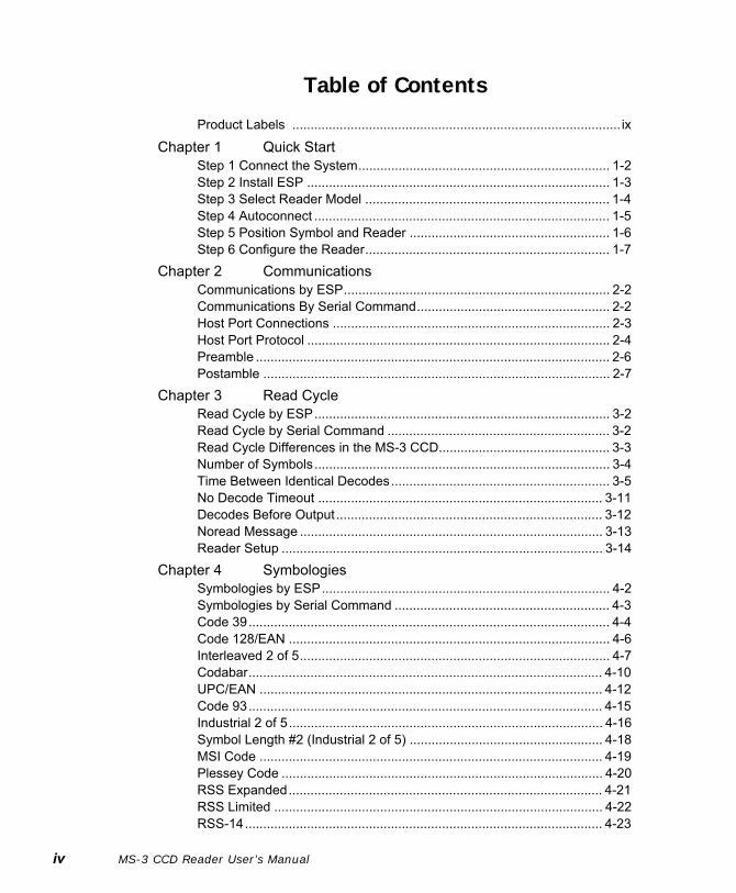
Table of Contents
Product Labels .......................................................................................... ix
Chapter 1 Quick StartStep 1 Connect the System..................................................................... 1-2Step 2 Install ESP ................................................................................... 1-3Step 3 Select Reader Model ................................................................... 1-4Step 4 Autoconnect ................................................................................. 1-5Step 5 Position Symbol and Reader ....................................................... 1-6Step 6 Configure the Reader................................................................... 1-7
Chapter 2 CommunicationsCommunications by ESP......................................................................... 2-2Communications By Serial Command..................................................... 2-2Host Port Connections ............................................................................ 2-3Host Port Protocol ................................................................................... 2-4Preamble ................................................................................................. 2-6Postamble ............................................................................................... 2-7
Chapter 3 Read CycleRead Cycle by ESP................................................................................. 3-2Read Cycle by Serial Command ............................................................. 3-2Read Cycle Differences in the MS-3 CCD............................................... 3-3Number of Symbols................................................................................. 3-4Time Between Identical Decodes............................................................ 3-5No Decode Timeout .............................................................................. 3-11Decodes Before Output......................................................................... 3-12Noread Message ................................................................................... 3-13Reader Setup ........................................................................................ 3-14
Chapter 4 SymbologiesSymbologies by ESP............................................................................... 4-2Symbologies by Serial Command ........................................................... 4-3Code 39................................................................................................... 4-4Code 128/EAN ........................................................................................ 4-6Interleaved 2 of 5..................................................................................... 4-7Codabar................................................................................................. 4-10UPC/EAN .............................................................................................. 4-12Code 93................................................................................................. 4-15Industrial 2 of 5...................................................................................... 4-16Symbol Length #2 (Industrial 2 of 5) ..................................................... 4-18MSI Code .............................................................................................. 4-19Plessey Code ........................................................................................ 4-20RSS Expanded...................................................................................... 4-21RSS Limited .......................................................................................... 4-22RSS-14.................................................................................................. 4-23
iv MS-3 CCD Reader User’s Manual

Symbology ID ........................................................................................ 4-24
Chapter 5 UtilitiesUtilities by ESP Menu .............................................................................. 5-2Summary of Utilities Commands ............................................................. 5-2Firmware.................................................................................................. 5-3Device Control ......................................................................................... 5-4Defaulting/Saving/Resetting .................................................................... 5-4Reader Status Requests ......................................................................... 5-5
Chapter 6 Terminal ModeTerminal Window..................................................................................... 6-2Find Function........................................................................................... 6-3Macros..................................................................................................... 6-4Terminal Window Functions .................................................................... 6-5
AppendicesAppendix A General Specifications .........................................................A-2Appendix B Electrical Specifications .......................................................A-4Appendix C Connectivity .........................................................................A-5Appendix D Serial Configuration Commands ........................................A-10Appendix E Serial Command Format ....................................................A-12Appendix F ASCII Table ........................................................................A-14Appendix G Defaulting/Saving/Resetting ..............................................A-15Appendix H Object Detector ..................................................................A-17Appendix I Formulas for Number of Decodes .......................................A-18Appendix J Operational Tips .................................................................A-20Appendix K Glossary of Terms..............................................................A-21
MS-3 CCD Reader User’s Manual v

Table of Contents
Table 3-1 Filters by Symbol Size ............................................................. 3-15Table 5-1 Software Reset/Save/Recall Commands ................................... 5-4Table A-1 MS-3 CCD Host Connector, 15-pin ...........................................A-4Table A-2 Host 25-pin Connector ..............................................................A-8Table A-3 Trigger 4-pin Connector ............................................................A-8Table A-4 Power 3-pin Connector ..............................................................A-8Table A-5 Reader 15-pin Connector ..........................................................A-8Table A-6 Network 25-pin Connector .........................................................A-8Table A-7 MS-3 CCD Serial Configuration Commands ...........................A-10Table A-8 ASCII Table with Control Characters .......................................A-14Table A-9 Software Reset/Save/Recall Commands ................................A-15
List of Figures
Figure 1-1 Hardware Connections ............................................................. 1-2Figure 1-2 Symbol/Reader Position ........................................................... 1-6Figure 3-1 External Level Trigger .............................................................. 3-7Figure 3-2 Trigger Edge ............................................................................. 3-8Figure 3-3 Filter Selection ........................................................................ 3-16Figure 6-1 Terminal Window ...................................................................... 6-2Figure A-1 MS-3 CCD Dimensions ............................................................A-2Figure A-2 MS-3 Right Angle Dimensions .................................................A-2Figure A-3 MS-3 CCD Read Ranges .........................................................A-3Figure A-4 MS-3/IB-131 Typical Setup ......................................................A-5Figure A-5 IC-332 READER Pinouts .........................................................A-6Figure A-6 IC-332 EXTERNAL Pinouts (to IB-131) ....................................A-6Figure A-7 IB-131 Mechanical ...................................................................A-9Figure A-8 Hyperterminal Dialog ..............................................................A-11Figure A-1 Object Detector ......................................................................A-17Figure A-2 Ladder ....................................................................................A-18Figure A-3 Picket Fence ..........................................................................A-18Figure A-4 Angled Picket Fence ..............................................................A-19
vi MS-3 CCD Reader User’s Manual
About the MS-3 CCD Reader
At 270 decodes per second, the MS-3 CCD offers the best read performance in its class of embedded compact CCD readers. Advanced CCD technology coupled with pro-prietary algorithms makes reading small, damaged, or poorly printed symbols routine. The ultra-compact size and wide read angle allow for flexible mounting and position-ing when embedded into OEM instruments.
About This Manual
This manual provides complete information on setting up, installing, and configuring the reader. The chapters are presented in the order in which a reader might be setup and made ready for industrial operation. Host serial commands are presented side-by-side with ESP menus.
Host Communications
There are two ways the reader can be programmed:1. Microscan’s Windows based ESP (Easy Setup Program), the preferred method,
which offers point-and-click ease of use and visual responses to user adjustments.
2. Serial commands such as <K100,1> can be sent from a terminal program. They can also be sent from the Terminal or Utility window within ESP.
Note: You can learn the current setting of any parameter by inserting a question mark after the number, as in <K100?> To see all “K” commands, send <K?>.
Highlighting
Serial commands, selections inside instructions, and menu defaults are highlighted in red bold. Cross-references are highlighted in blue. Web links and outside references are high-lighted in blue bold italics. References to menu topics are highlighted in Bold Initial Caps. References to topic headings within this manual or other documents are enclosed in quotation marks.
MS-3 CCD Reader User’s Manual vii

Product LabelsThe following labels are located on the top and bottom of the MS-3 CCD Reader:
Approvals
This equipment is in compliance or approved by the following organizations:• UL (Underwriters Laboratories, Inc.)
• cUL (UL mark of Canada)
• FCC (Federal Communication Commission)
• CE Compliant
• BSMI (Bureau of Standards, Metrology and Inspection)P
WR
GO
OD
RE
AD
11-000069-01
MS-3CCD
THIS DEVICE COMPLIES WITH PART 15 OF THE FCC RULES. OPERATION IS SUBJECT TO THE FOLLOWING TWO CONDITIONS. (1) THIS DEVICE MAY NOT CAUSE HARMFUL INTERFERENCE, AND (2) THIS DEVICE MUST ACCEPT ANY INTERFERENCE RECEIVED, INCLUDING INTERFERENCE THAT MAY CAUSE UNDESIRED OPERATION.
CLASS B DEVICE
LISTED UL 609504k68
www.microscan.com 1201 SW 7th St. Renton, WA 98055
R US
Made in USA
5V1 Watt max.
0.90"(22.9 mm)
11-000070-01
Top Bottom
viii MS-3 CCD Reader User’s Manual

Quick Start
Chapter Contents
This section is designed to get the reader up and running quickly so the user can get a sense of its capabilities and test sample bar code symbols. Detailed setup information for configuring the reader for your specific application can be obtained in the subse-quent chapters.
Chapter
1
Step 1 Connect the System .....................................................................1-2Step 2 Install ESP....................................................................................1-3Step 3 Select Reader Model ....................................................................1-4Step 4 Autoconnect .................................................................................1-5Step 5 Position Symbol and Reader........................................................1-6Step 6 Configure the Reader ...................................................................1-7
MS-3 CCD Reader User’s Manual 1-1
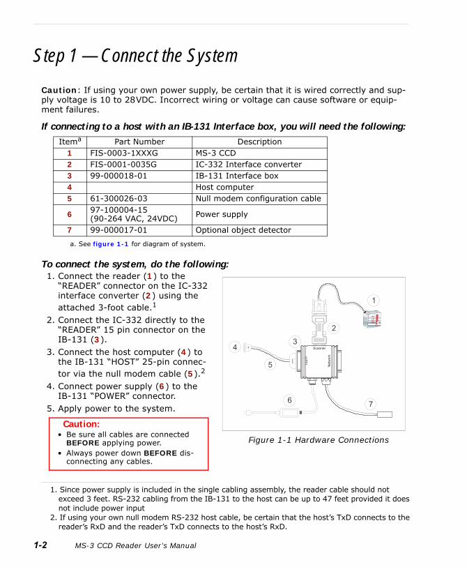
Step 1 — Connect the SystemCaution: If using your own power supply, be certain that it is wired correctly and sup-ply voltage is 10 to 28 VDC. Incorrect wiring or voltage can cause software or equip-ment failures.
If connecting to a host with an IB-131 Interface box, you will need the following:
To connect the system, do the following:1. Connect the reader (1) to the
“READER” connector on the IC-332 interface converter (2) using the attached 3-foot cable.1
2. Connect the IC-332 directly to the “READER” 15 pin connector on the IB-131 (3).
3. Connect the host computer (4) to the IB-131 “HOST” 25-pin connec-tor via the null modem cable (5).2
4. Connect power supply (6) to the IB-131 “POWER” connector.
5. Apply power to the system.
Itema
a. See figure 1-1 for diagram of system.
Part Number Description1 FIS-0003-1XXXG MS-3 CCD2 FIS-0001-0035G IC-332 Interface converter3 99-000018-01 IB-131 Interface box4 Host computer5 61-300026-03 Null modem configuration cable
6 97-100004-15 (90-264 VAC, 24VDC) Power supply
7 99-000017-01 Optional object detector
1. Since power supply is included in the single cabling assembly, the reader cable should not exceed 3 feet. RS-232 cabling from the IB-131 to the host can be up to 47 feet provided it does not include power input
2. If using your own null modem RS-232 host cable, be certain that the host’s TxD connects to the reader’s RxD and the reader’s TxD connects to the host’s RxD.
Figure 1-1 Hardware Connections
�
�
�
�
�
�
����
�������
���
�
Caution:• Be sure all cables are connected
BEFORE applying power.• Always power down BEFORE dis-
connecting any cables.
1-2 MS-3 CCD Reader User’s Manual

Chapter 1 Quick Start
Step 2 — Install ESP (ESP is short for Easy Setup Program.)With your reader connected to a host computer with Windows operating system, you can use the ESP to configure and control the reader. 1. Insert your Microscan CD into your computer’s CD drive. 2. Launch Setup.exe under ESP and follow the prompts.
If downloading from the web:
a) Go to http://www.microscan.com/downloadcenter/b) Enter company information.c) Select ESP and download to your computer hard drive.d) Extract ESP files to a directory of your choice.
3. Note where your ESP.exe file is stored on your hard drive.At the end of the install process, you should see the following icon on your desktop:
4. Click the ESP icon to start the program.
MS-3 CCD Reader User’s Manual 1-3
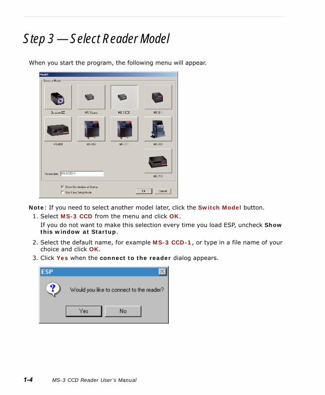
Step 3 — Select Reader ModelWhen you start the program, the following menu will appear.
Note: If you need to select another model later, click the Switch Model button.1. Select MS-3 CCD from the menu and click OK.
If you do not want to make this selection every time you load ESP, uncheck Show this window at Startup.
2. Select the default name, for example MS-3 CCD-1, or type in a file name of your choice and click OK.
3. Click Yes when the connect to the reader dialog appears.
1-4 MS-3 CCD Reader User’s Manual
Chapter 1 Quick Start
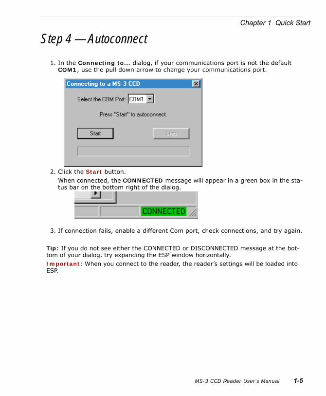
Step 4 — Autoconnect1. In the Connecting to... dialog, if your communications port is not the default
COM1, use the pull down arrow to change your communications port.
2. Click the Start button.When connected, the CONNECTED message will appear in a green box in the sta-tus bar on the bottom right of the dialog.
3. If connection fails, enable a different Com port, check connections, and try again.
Tip: If you do not see either the CONNECTED or DISCONNECTED message at the bot-tom of your dialog, try expanding the ESP window horizontally.Important: When you connect to the reader, the reader’s settings will be loaded into ESP.
MS-3 CCD Reader User’s Manual 1-5
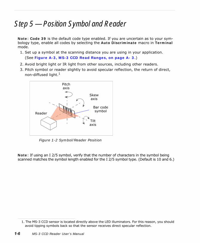
Step 5 — Position Symbol and ReaderNote: Code 39 is the default code type enabled. If you are uncertain as to your sym-bology type, enable all codes by selecting the Auto Discriminate macro in Terminal mode.1. Set up a symbol at the scanning distance you are using in your application.
(See Figure A-3, MS-3 CCD Read Ranges, on page A- 3.)
2. Avoid bright light or IR light from other sources, including other readers.3. Pitch symbol or reader slightly to avoid specular reflection, the return of direct,
non-diffused light.1
Note: If using an I 2/5 symbol, verify that the number of characters in the symbol being scanned matches the symbol length enabled for the I 2/5 symbol type. (Default is 10 and 6.)
1. The MS-3 CCD sensor is located directly above the LED illuminators. For this reason, you should avoid tipping symbols back so that the sensor receives direct specular reflection.
Figure 1-2 Symbol/Reader Position
Bar code symbol
Skewaxis
Tiltaxis
Pitchaxis
Reader
1-6 MS-3 CCD Reader User’s Manual
Chapter 1 Quick Start
Step 6 — Configure the Reader See the succeeding chapters and Appendices to see specific configuration command explanations for both ESP and serial commands.
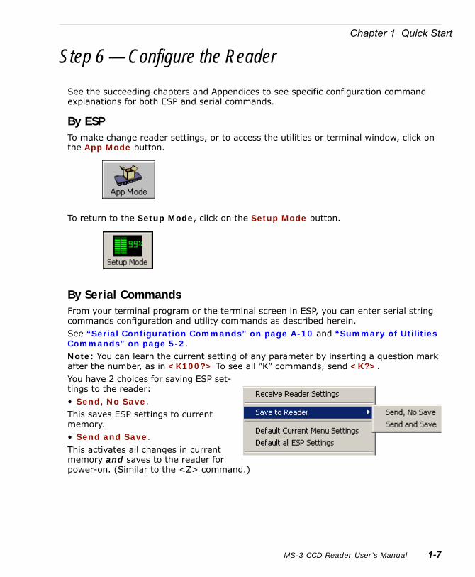
By ESPTo make change reader settings, or to access the utilities or terminal window, click on the App Mode button.
To return to the Setup Mode, click on the Setup Mode button.
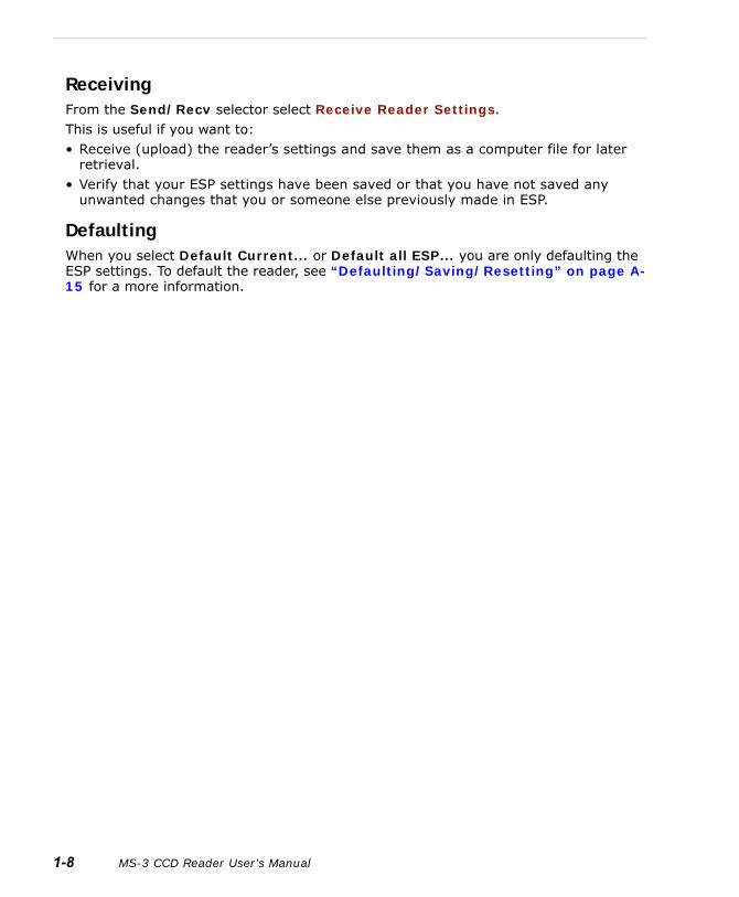
By Serial CommandsFrom your terminal program or the terminal screen in ESP, you can enter serial string commands configuration and utility commands as described herein.See “Serial Configuration Commands” on page A-10 and “Summary of Utilities Commands” on page 5-2.Note: You can learn the current setting of any parameter by inserting a question mark after the number, as in <K100?> To see all “K” commands, send <K?>.You have 2 choices for saving ESP set-tings to the reader:• Send, No Save. This saves ESP settings to current memory. • Send and Save. This activates all changes in current memory and saves to the reader for power-on. (Similar to the <Z> command.)
MS-3 CCD Reader User’s Manual 1-7
ReceivingFrom the Send/Recv selector select Receive Reader Settings.This is useful if you want to:• Receive (upload) the reader’s settings and save them as a computer file for later
retrieval.• Verify that your ESP settings have been saved or that you have not saved any
unwanted changes that you or someone else previously made in ESP.
DefaultingWhen you select Default Current... or Default all ESP... you are only defaulting the ESP settings. To default the reader, see “Defaulting/Saving/Resetting” on page A-15 for a more information.
1-8 MS-3 CCD Reader User’s Manual

Communications
Chapter Contents
With Microscan’s ESP (Easy Setup Program), configuration changes can be made in the ESP menus, then sent and saved to your reader. The user can also send serial com-mands to the reader via the ESP’s Terminal window.This section includes connecting parameters and options for communicating by the aux-iliary port and various interfaces.Note: When assigning characters in user-defined fields, the characters NULL <> and , can only be entered through embedded menus, not through ESP or serial commands.
Note: Default settings for establishing communications are:Baud = 9600
Parity = Even
Stop Bits = One
Data Bits = Seven
Flow Control = None
Note: You can learn the current setting of any parameter by inserting a question mark after the number, as in <K100?> To see all “K” commands, send <K?>.
Chapter
2
Communications by ESP .........................................................................2-2Communications By Serial Command .....................................................2-2Preamble .................................................................................................2-6Postamble................................................................................................2-7
MS-3 CCD Reader User’s Manual 2-1
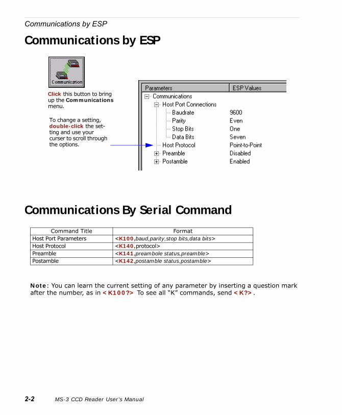
Communications by ESP
Communications by ESP
Communications By Serial Command
Note: You can learn the current setting of any parameter by inserting a question mark after the number, as in <K100?> To see all “K” commands, send <K?>.
Command Title FormatHost Port Parameters <K100,baud,parity,stop bits,data bits>Host Protocol <K140, protocol>Preamble <K141,preambole status,preamble>Postamble <K142,postamble status,postamble>
Click this button to bring up the Communications menu.
To change a setting, double-click the set-ting and use your curser to scroll through the options.
2-2 MS-3 CCD Reader User’s Manual
Chapter 2 Communications
Host Port Connections
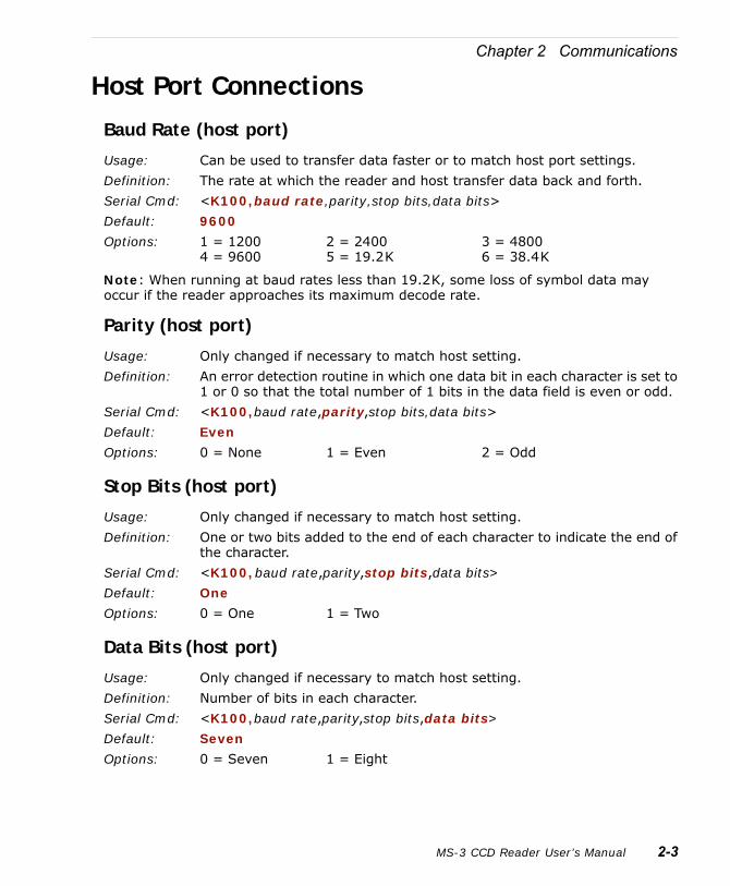
Baud Rate (host port)
Note: When running at baud rates less than 19.2 K, some loss of symbol data may occur if the reader approaches its maximum decode rate.
Parity (host port)
Stop Bits (host port)
Data Bits (host port)
Usage: Can be used to transfer data faster or to match host port settings.
Definition: The rate at which the reader and host transfer data back and forth.
Serial Cmd: <K100, baud rate,parity,stop bits,data bits>
Default: 9600
Options: 1 = 1200 2 = 2400 3 = 4800 4 = 9600 5 = 19.2 K 6 = 38.4 K
Usage: Only changed if necessary to match host setting.
Definition: An error detection routine in which one data bit in each character is set to 1 or 0 so that the total number of 1 bits in the data field is even or odd.
Serial Cmd: <K100, baud rate,parity,stop bits,data bits>
Default: Even
Options: 0 = None 1 = Even 2 = Odd
Usage: Only changed if necessary to match host setting.
Definition: One or two bits added to the end of each character to indicate the end of the character.
Serial Cmd: <K100, baud rate,parity,stop bits,data bits>
Default: One
Options: 0 = One 1 = Two
Usage: Only changed if necessary to match host setting.
Definition: Number of bits in each character.
Serial Cmd: <K100, baud rate,parity,stop bits,data bits>
Default: Seven
Options: 0 = Seven 1 = Eight
MS-3 CCD Reader User’s Manual 2-3

Host Port Protocol
Host Port Protocol
Point-to-Point (standard)
Usage: In general, the point-to-point protocols will work well in most applica-tions. They require no address and must use RS-232 or RS-422 commu-nications standards.
Definition: Protocols define the sequence and format in which information is trans-ferred between the reader and the host, or in the case of Multidrop, between readers and a concentrator.
Serial Cmd: <K140,protocol>
Default: Point-to-Point
Options: 0 = Point-to-Point 1 = Point-to-Point with RTS/CTS2 = Point-to-Point with XON/XOFF 3 = Point-to-Point with RTS/CTS & XON/XOFF
4 = Polling Mode D 5 = Multidrop 6 = User Defined7 = User Defined Multidrop
If selecting one of the options from 0 to 4 (Point-to-Point, Point-to-Point with RTS/CTS, Point-to-Point with XON/XOFF, Point-to-Point with RTS/CTS and XON/XOFF, or Polling Mode D), use the <K140,protocol> format.Option 5 through 7 are special cases and discussed later in this section.
Usage: Used only with RS232 or RS422.
Definition: Standard Point-to-Point requires no address and sends data to the host whenever it is available, without any request or handshake from the host.
Serial Cmd: <K140, 0>
2-4 MS-3 CCD Reader User’s Manual
Chapter 2 Communications
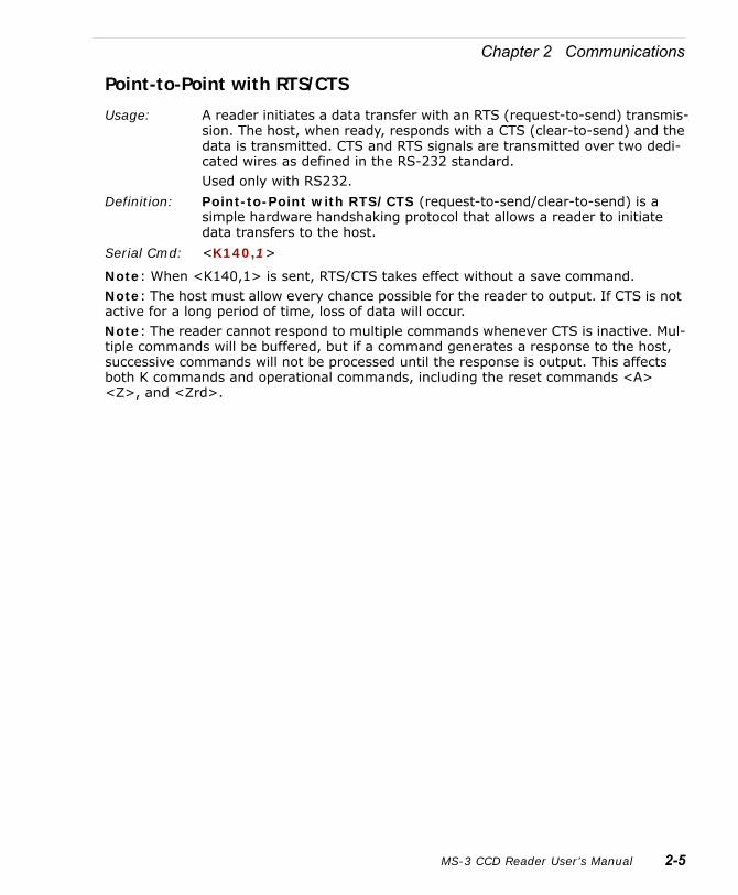
Point-to-Point with RTS/CTS
Note: When <K140,1> is sent, RTS/CTS takes effect without a save command.Note: The host must allow every chance possible for the reader to output. If CTS is not active for a long period of time, loss of data will occur.Note: The reader cannot respond to multiple commands whenever CTS is inactive. Mul-tiple commands will be buffered, but if a command generates a response to the host, successive commands will not be processed until the response is output. This affects both K commands and operational commands, including the reset commands <A> <Z>, and <Zrd>.
Usage: A reader initiates a data transfer with an RTS (request-to-send) transmis-sion. The host, when ready, responds with a CTS (clear-to-send) and the data is transmitted. CTS and RTS signals are transmitted over two dedi-cated wires as defined in the RS-232 standard.Used only with RS232.
Definition: Point-to-Point with RTS/CTS (request-to-send/clear-to-send) is a simple hardware handshaking protocol that allows a reader to initiate data transfers to the host.
Serial Cmd: <K140,1>
MS-3 CCD Reader User’s Manual 2-5
Preamble
Preamble
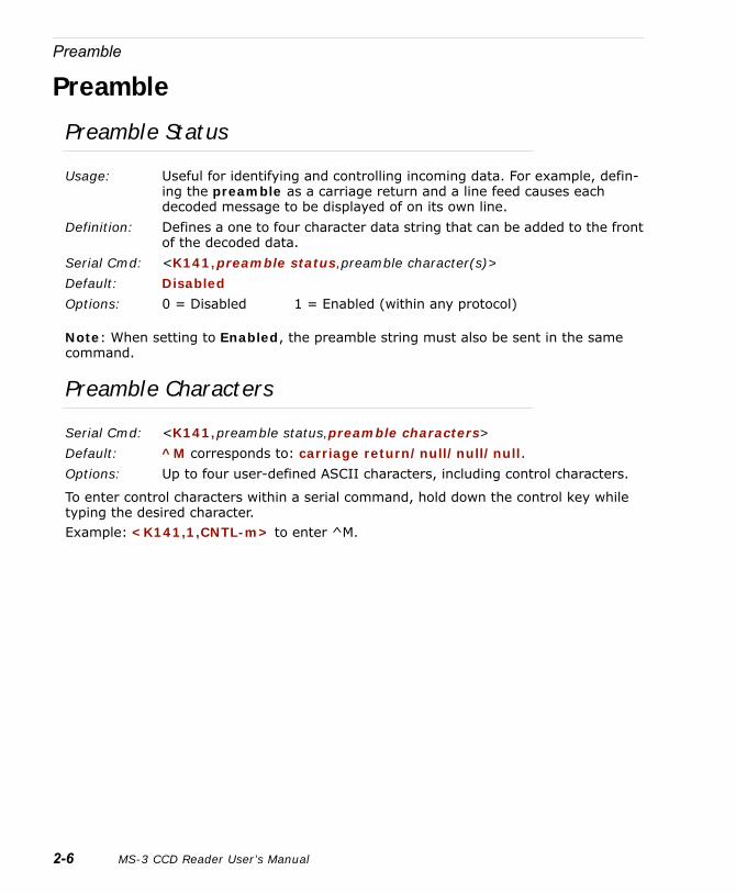
Preamble Status
Note: When setting to Enabled, the preamble string must also be sent in the same command.
Preamble Characters
To enter control characters within a serial command, hold down the control key while typing the desired character. Example: <K141,1,CNTL-m> to enter ^M.
Usage: Useful for identifying and controlling incoming data. For example, defin-ing the preamble as a carriage return and a line feed causes each decoded message to be displayed of on its own line.
Definition: Defines a one to four character data string that can be added to the front of the decoded data.
Serial Cmd: <K141, preamble status,preamble character(s)>
Default: Disabled
Options: 0 = Disabled 1 = Enabled (within any protocol)
Serial Cmd: <K141, preamble status,preamble characters>
Default: ^M corresponds to: carriage return/null/null/null.
Options: Up to four user-defined ASCII characters, including control characters.
2-6 MS-3 CCD Reader User’s Manual
Chapter 2 Communications
Postamble
Postamble Status
Note: When setting to Enabled, the postamble string must also be sent in the same command.
Postamble Characters
To enter control characters within a serial command, hold down the control key while typing the desired character.Example: <K142,CNTL-m CNTL-j> to enter ^M^J.
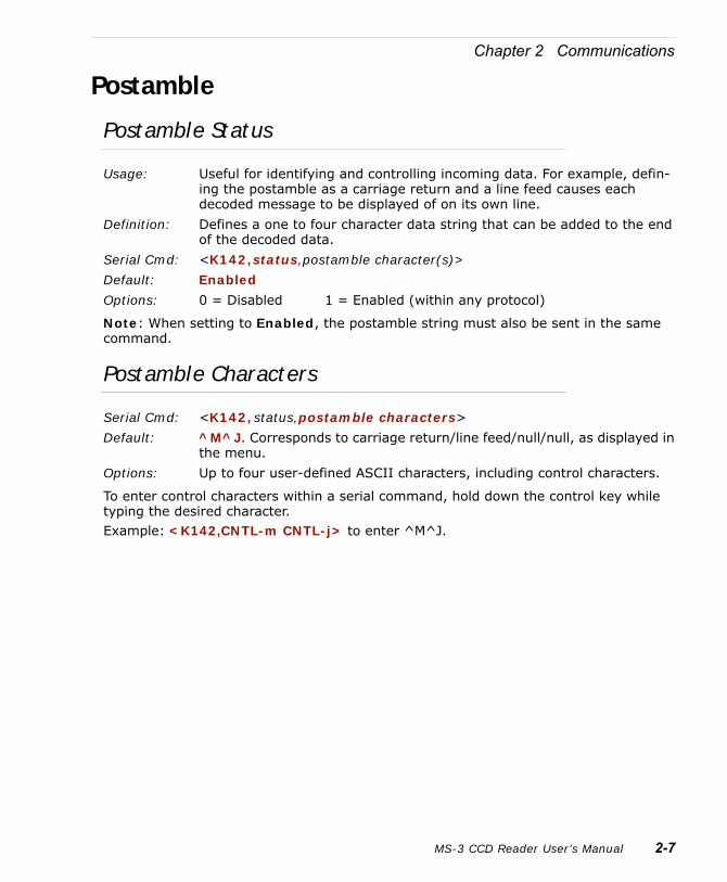
Usage: Useful for identifying and controlling incoming data. For example, defin-ing the postamble as a carriage return and a line feed causes each decoded message to be displayed of on its own line.
Definition: Defines a one to four character data string that can be added to the end of the decoded data.
Serial Cmd: <K142, status,postamble character(s)>
Default: Enabled
Options: 0 = Disabled 1 = Enabled (within any protocol)
Serial Cmd: <K142, status,postamble characters>
Default: ^M^J. Corresponds to carriage return/line feed/null/null, as displayed in the menu.
Options: Up to four user-defined ASCII characters, including control characters.
MS-3 CCD Reader User’s Manual 2-7

Postamble
2-8 MS-3 CCD Reader User’s Manual
Read Cycle
Chapter Contents
After you’ve established communications and completed basic read rate testing, you will need to address the spatial and timing parameters associated with your application. In a typical operation a bar coded item moves along a line past a reader. A trigger or timer activates a read cycle during which the reader actively searches for symbols. You will need to decide how to initiate the read cycle and how and when to end it.Note: When assigning characters in user-defined fields, the characters NULL <> and , can only be entered through embedded menus, not through ESP or serial commands.Note on Serial Commands: To preserve continuity with other Microscan products, some serial configuration commands may include 0s (zeros) or 1s as placeholders. In order for a these commands to be implemented, the parameter values or a comma must be included.
Chapter
3
Read Cycle by ESP .................................................................................3-2Read Cycle by Serial Command..............................................................3-2Read Cycle Differences in the MS-3 CCD...............................................3-3Number of Symbols .................................................................................3-4Time Between Identical Decodes ............................................................3-5No Decode Timeout ...............................................................................3-11Decodes Before Output .........................................................................3-12Noread Message ...................................................................................3-13Reader Setup.........................................................................................3-14
MS-3 CCD Reader User’s Manual 3-1
Read Cycle by ESP
Read Cycle by ESP
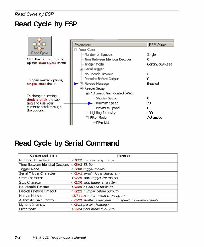
Read Cycle by Serial CommandCommand Title Format
Number of Symbols <K222, number of symbols>Time Between Identical Decodes <K503,TBID>Trigger Mode <K200,trigger mode>Serial Trigger Character <K201, serial trigger character>Start Character <K229,start trigger character>Stop Character <K230, stop trigger character>No Decode Timeout <K220, no decode timeout>Decodes Before Timeout <K221, number before output>Noread Message <K714, status,noread message>Automatic Gain Control <K522,shutter speed,minimum speed,maximum speed>Lighting Intensity <K523,percent lighting>Filter Mode <K524,filter mode,filter list>
Click this Button to bring up the Read Cycle menu
To change a setting, double-click the set-ting and use your curser to scroll through the options.
To open nested options, single-click the +.
3-2 MS-3 CCD Reader User’s Manual

Chapter 3 Read Cycle
Read Cycle Differences in the MS-3 CCDImportant: With the MS-3 CCD, symbol data is output as soon as it is decoded. There is no “end of read cycle” option. Because of this limitation, multisymbol operations can only be emulated by controlling the read cycle duration and the time allowed between identical consecutive decodes.In read cycle timing, the MS-3 CCD differs from standard Microscan readers in the fol-lowing ways:1. In Single symbol mode, a read cycle ends only on a decode, falling trigger or a
timeout.2. In Multiple symbol mode, the read cycle begins upon a triggered event, but
starts over after any symbol has been decoded.3. There is no “new trigger” feature.4. There is no timeout for level trigger read cycle mode.
In general, read cycle timeout and end of read cycle outputs are determined by “Trig-ger Mode”, “No Decode Timeout”, and “Time Between Identical Decodes”.
MS-3 CCD Reader User’s Manual 3-3

Number of Symbols
Number of SymbolsNote: Multiple symbol scanning is different in the MS-3 CCD from other Microscan products in that the multisymbol operation is emulated by setting timeout conditions and timing between identical decodes.
Usage: Commonly used where a shipping symbol contains individual symbols for part number, quantity, etc.
Definition: Determines whether a single symbol or multiple symbols can be read and decoded in a single read cycle.
Conditions: The following conditions apply:1. When Number of Symbols is set to Single, the read cycle ends
when one symbol is decoded and output. 2. When Number of Symbols is set to Multiple, all decoded symbol
data (for both the same and different symbols) are output while the read cycle is active and/or no timeout has occurred.
3. If set to Multiple and TBIDa is less than the decode time (typically about 4 mS), the same symbol can be output multiple times.
a. Time Between Identical Decodes
Serial Cmd: <K222, number of symbols>
Default: Single
Options: 0 = Multiple 1 = Single
3-4 MS-3 CCD Reader User’s Manual
Chapter 3 Read Cycle
Time Between Identical Decodes
Usage: Can be used to prevents repetition of decode outputs. Also useful for emulating multisymbol operations. When used in conjunction with Number of Symbols set to Multiple, Timing Between Identical Decodes can be set so that more than one symbol can be read within a read cycle.
Definition: Sets the length of time that the reader will wait before allowing a sym-bol that has been output from outputting again.
Serial Cmd: <K503,TBID>
Default: 0
Options: 0 to 2550 mS.
MS-3 CCD Reader User’s Manual 3-5
Time Between Identical Decodes
Trigger
Trigger Mode
Continuous Read
Continuous Read 1 Emulation
Caution: In automated environments, Continuous Read 1 Emulation is not recom-mended because there is no one to verify that a symbol was missed.
Definition: The type of trigger event that will initiate the read cycle.
Serial Cmd: <K200,trigger mode>
Default: Continuous
Options: 0 = Continuous Read See “Continuous Read 1 Emula-tion” on page 3-6. 2 = External Level 3 = External Edge 4 = Serial Data 5 = Serial Data & External Edge 6 = Custom (custom configured via symbol setup)
Usage: Continuous Read is useful in testing symbol readability or reader func-tions. It is not recommended for normal operations.
Definition: In Continuous Read, trigger input options are disabled, the reader is always in the read cycle, and it will attempt to decode and output every scan crossing a symbol.
Serial Cmd: <K200, 0>
Usage: Continuous Read 1 Emulation can be useful in applications where it is not feasible to use a trigger and all succeeding symbols contain different information. It is also effective in applications where the objects are hand-presented.
Definition: In Continuous Read 1 Emulation the reader triggers whenever it decodes a new symbol.
Operation: Continuous Read 1 is emulated by enabling TBID to any value other than zero and works best if the TBID timeout is longer than the decode time.
Hint: Set TBID (“Time Between Identical Decodes” on page 3-5) to maxi-mum to ensure enough time for decode to take place.
3-6 MS-3 CCD Reader User’s Manual

Chapter 3 Read Cycle
External Level
Important: Level and Edge apply to the active state of the trigger that exists while the object is in a read cycle. Negative is the electrical state (0 V/gnd) of the trigger sig-nal associated with the appearance of an object. Positive is the electrical state of the trigger signal received by the reader and associated with the subsequent disappearance of the object.
Usage: This mode is effective in an application where the speeds of the convey-ing apparatus are variable and the time the reader spends scanning each object is not predictable. It also allows the user to determine if a noread has occurred.
Definition: External Level allows the read cycle to begin when a trigger (change of state) from an external sensing device is received. The read cycle endures until the object moves out of the sensor range and the active trigger state changes again.
Serial Cmd: <K200,2>
��
��������������
��������������
��
�
������
�
������
Figure 3-1 External Level Trigger
Initiate Read Cycle:Object # 1, moving in front of the detector beam, causes a change in the trigger state, initi-ating the read cycle.
End Read Cycle:The same object, moving out of the detector beam, causes another change in the trigger state, ending the read cycle.
MS-3 CCD Reader User’s Manual 3-7
Time Between Identical Decodes
External Trigger Edge
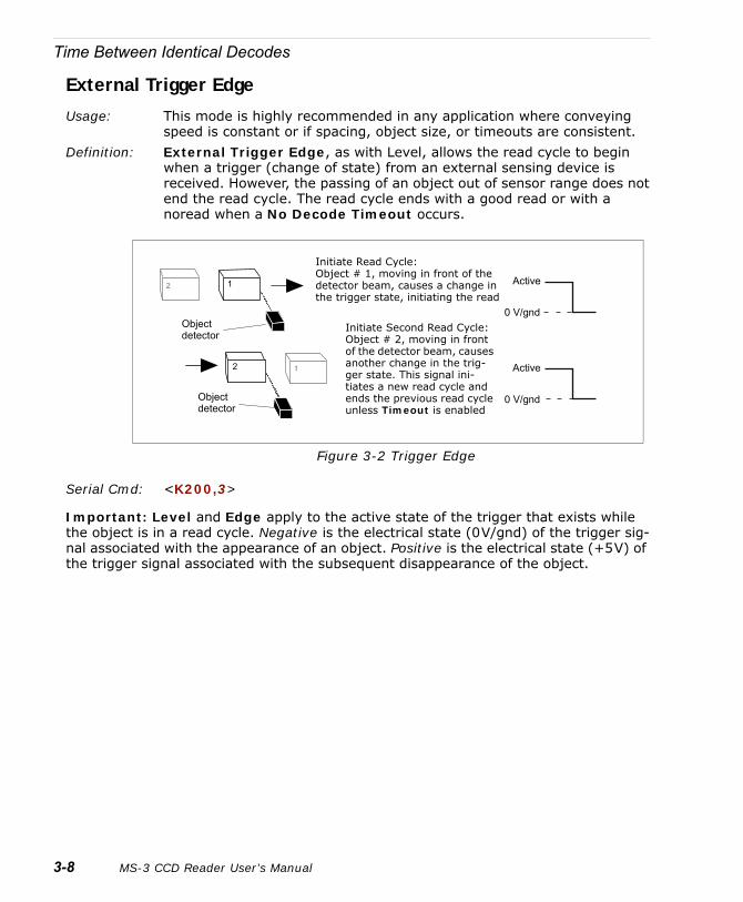
Important: Level and Edge apply to the active state of the trigger that exists while the object is in a read cycle. Negative is the electrical state (0 V/gnd) of the trigger sig-nal associated with the appearance of an object. Positive is the electrical state (+5 V) of the trigger signal associated with the subsequent disappearance of the object.
Usage: This mode is highly recommended in any application where conveying speed is constant or if spacing, object size, or timeouts are consistent.
Definition: External Trigger Edge, as with Level, allows the read cycle to begin when a trigger (change of state) from an external sensing device is received. However, the passing of an object out of sensor range does not end the read cycle. The read cycle ends with a good read or with a noread when a No Decode Timeout occurs.
Serial Cmd: <K200,3>
��
��������������
��
��������������
���� �
������
���� �
������
Figure 3-2 Trigger Edge
Initiate Read Cycle:Object # 1, moving in front of the detector beam, causes a change in the trigger state, initiating the read
Initiate Second Read Cycle:Object # 2, moving in front of the detector beam, causes another change in the trig-ger state. This signal ini-tiates a new read cycle and ends the previous read cycle unless Timeout is enabled
3-8 MS-3 CCD Reader User’s Manual
Chapter 3 Read Cycle
Serial Data
Serial Data or External Edge
Serial Trigger Character
Note: Serial Data or Serial Data & Edge triggering mode must be enabled for Serial Trigger Character to take effect.
Usage: Highly recommended in any application where conveying speed is con-stant or if spacing, object size, or timeouts are consistent.
Definition: In Serial Data, the reader accepts an ASCII character from the host or controlling device as a trigger to start a read cycle. A Serial Data trigger behaves the same as an External Edge trigger.
Serial Cmd: <K200,4>
Usage: Serial Data or External Edge is seldom used but can be useful in an application that primarily uses an external sensing device but occasion-ally needs to be manually triggered.
Definition: In this mode the reader accepts either a serial ASCII character or an external trigger pulse to start the read cycle.
Serial Cmd: <K200,5>
Usage: Useful in applications where a single serial character enclosed in angle brackets initiates the read cycle.
Definition: A trigger character is one that starts the read cycle, is enclosed by delim-iters < > and can only be sent when the trigger mode is set to Serial Data or Serial Data & Edge.
Serial Cmd: <K201, serial trigger character>
Default: ^] (corresponds to <GS>
Options: Any single ASCII character, including control characters, except NUL (00H), an existing host command character, or an on-line protocol char-acter.
MS-3 CCD Reader User’s Manual 3-9

Time Between Identical Decodes
Non-delimited Start and Stop Characters
Note: If the serial trigger character that you assign is already assigned as an opera-tional command—for example a “Z” character that is used in the <Z> command—the command will no longer function as intended.Both Start and Stop non-delimited characters can be defined and will function accord-ing to the trigger event, as follows:When defining Start and Stop trigger characters, the following rules apply:• In External Edge the reader looks only for the Start Trigger Character and
ignores any Stop Trigger Character that may be defined.• In External Level, the Start Trigger Character begins the read cycle and Stop
Trigger Character ends it. Note that even after a symbol has been decoded and the symbol data transmitted, the reader remains in External Level trigger read cycle until a Stop character is received.
• In Serial Data & Edge trigger mode, command, either a Start Trigger Character or a hardware trigger can start an Edge trigger read cycle.
Start Character (non-delimited)
Stop Character (non-delimited)
See Appendix F — “ASCII Table” for ASCII character information.
Usage: It is useful in applications where different characters are required to start and end a read cycle.
Definition: A single ASCII host serial trigger character that starts the read cycle and is not enclosed by delimiters such as < and >.
Serial Cmd: <K229, start trigger character>
Default: Null (disabled)
Options: Two hex digits representing an ASCII character except < , and >.
Usage: It is useful in applications where different characters are required to start and end a read cycle.
Definition: A single ASCII host serial trigger character that ends the read cycle and is not enclosed by delimiters such as < and >.
Serial Cmd: <K230, stop trigger character>
Default: Null (disabled)
Options: Two hex digits representing an ASCII character except <, >, XON and XOFF.
3-10 MS-3 CCD Reader User’s Manual
Chapter 3 Read Cycle
No Decode Timeout
The MS-3 CCD times out if no symbol is decoded during the No Decode Timeout period. If a symbol is decoded before the timeout expires, then the timeout period starts over again.No Decode Timeout only applies to Edge, Serial Data, and Serial Data and Edge trigger modes.In Single symbol mode (<K222,1>), No Decode Timeout is the maximum amount of time the reader will attempt to decode after a trigger is activated.In Multiple symbol mode (<K222,0>), No Decode Timeout is the time in which there are no decodes, not the time since the trigger went active. That is, if the reader contin-ues to decode symbols in front of it, it will not exit the read cycle unless the time between decodes exceeds the time set in No Decode Timeout.For Level trigger mode, the read cycle ends when the trigger falls, or a symbol is decoded and output in single-symbol mode.
Usage: Useful in many tightly controlled applications requiring a read cycle to end before the next object appears.
Definition: The duration of the read cycle as measured from either the beginning of the read cycle or from the last decode.
Serial Cmd: <K220, 0,no decode timeout>a
a. The first parameter is always a zero(0) and does not change.
Default: 2 (seconds)
Options: 1 to 4095 seconds
MS-3 CCD Reader User’s Manual 3-11
Decodes Before Output
Decodes Before OutputNote: When setting up, determine if the reader’s scan rate is capable of scanning your longest symbol the required number of times.
If in Single symbol mode it doesn’t achieve the number of required decodes during the read cycle, a noread will be sent.Note: Higher settings will decrease throughput speed.
Usage: This is a very useful feature to increase reliability of reads for symbolo-gies that do not have internal error checking such as I 2/5.
Definition: The number of decodes required per symbol before a its data is sent. It requires the reader to successfully decode a symbol a designated number of times before it is sent.
Serial Cmd: <K221, number before output>
Default: 0
Options: 0 to 10 (0 = “auto adaptive”)
3-12 MS-3 CCD Reader User’s Manual

Chapter 3 Read Cycle
Noread MessageNote: A Noread Message can only be transmitted when in Single symbol mode and no decodes occur.
Noread Status
Noread Message
Note: A Noread Message is not output when in scanning disabled mode (an <I> command has been sent).
Usage: Used in applications where the host needs serial verification that a sym-bol has not been read and especially useful in new print verification.
Definition: When enabled, and if no symbol has been decoded before timeout or the end of the read cycle, the noread message will be transmitted to the host.
Serial Cmd: <K714, status,noread message>
Default: Enabled
Options: 0 = Disabled 1 = Enabled
Definition: Any combination of ASCII characters can be defined as the noread mes-sage.
Serial Cmd: <K714, status,noread message>
Default: NOREAD
Options: 1 to 20 ASCII characters.
MS-3 CCD Reader User’s Manual 3-13
Reader Setup
Reader Setup
Automatic Gain Control
Allows shutter speeds to be controlled automatically, set to a specific value, or defined within a fixed range.
Shutter Speed
Minimum Speed
Maximum Speed
Definition: Shutter speed is the time that the sensor is exposed to light.
Usage: Faster shutter speeds may be necessary in fast moving applications. Slower shutter speeds are useful in slower and lower contrast applica-tions.
Serial Cmd: <K522,shutter speed,minimum speed,maximum speed>
Default: 0 (0 = automatic)
Options: 70 to 65535
Definition: Slowest shutter speed and longest time that the sensor is exposed to the light.
Usage: Applications with variable speeds, symbol sizes and distances.
Serial Cmd: <K522,shutter speed,minimum speed,maximum speed>
Default: 70
Options: 70 to 65535
Definition: Fastest shutter speed and shortest time that the sensor is exposed to the light.
Usage: Applications with variable speeds, symbol sizes and distances.
Serial Cmd: <K522,shutter speed,minimum speed,maximum speed>
Default: 250 (1/250 second)
Options: 70 to 65535
3-14 MS-3 CCD Reader User’s Manual
Chapter 3 Read Cycle
Lighting Intensity
Filter Mode
Filter List
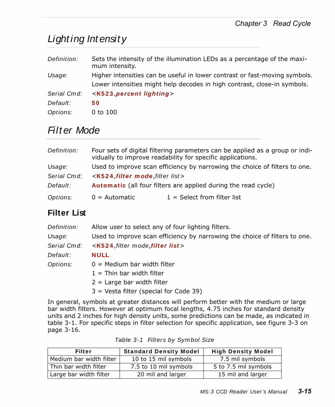
In general, symbols at greater distances will perform better with the medium or large bar width filters. However at optimum focal lengths, 4.75 inches for standard density units and 2 inches for high density units, some predictions can be made, as indicated in table 3-1. For specific steps in filter selection for specific application, see figure 3-3 on page 3-16.
Definition: Sets the intensity of the illumination LEDs as a percentage of the maxi-mum intensity.
Usage: Higher intensities can be useful in lower contrast or fast-moving symbols.Lower intensities might help decodes in high contrast, close-in symbols.
Serial Cmd: <K523,percent lighting>
Default: 50
Options: 0 to 100
Definition: Four sets of digital filtering parameters can be applied as a group or indi-vidually to improve readability for specific applications.
Usage: Used to improve scan efficiency by narrowing the choice of filters to one.
Serial Cmd: <K524,filter mode,filter list>
Default: Automatic (all four filters are applied during the read cycle)
Options: 0 = Automatic 1 = Select from filter list
Definition: Allow user to select any of four lighting filters.
Usage: Used to improve scan efficiency by narrowing the choice of filters to one.
Serial Cmd: <K524,filter mode,filter list>
Default: NULL
Options: 0 = Medium bar width filter1 = Thin bar width filter2 = Large bar width filter3 = Vesta filter (special for Code 39)
Table 3-1 Filters by Symbol Size
Filter Standard Density Model High Density ModelMedium bar width filter 10 to 15 mil symbols 7.5 mil symbolsThin bar width filter 7.5 to 10 mil symbols 5 to 7.5 mil symbolsLarge bar width filter 20 mil and larger 15 mil and larger
MS-3 CCD Reader User’s Manual 3-15

Reader Setup
Filter Selection
When Filter Mode is set for Automatic, you can compare filter success rates in an actual scanning application by sending a <C> command from the Terminal window. Each filter will output its number of successes. In figure 3-3 the four filters (0 through 3) are shown in succession from left to right. Filter 1 acquires 95 reads, the others 0. The choice is obvious. When you enable Filter 1 in Filter List only, the other filters are omitted and the number of captures and decodes per second should significantly improve.
Figure 3-3 Filter Selection
Filter 0 Filter 2
Filter 1 Filter 3
3-16 MS-3 CCD Reader User’s Manual
Symbologies
Chapter Contents
This section describes the various symbol types that can be read and decoded by the reader.Code 39 is enabled by default. See http://www.aimglobal.org/standards/aimpubs.asp for additional information about symbologies.Note: When assigning characters in user-defined fields, the characters NULL <> and , can only be entered through embedded menus, not through ESP or serial commands.
Chapter
4
Symbologies by ESP ...............................................................................4-2Symbologies by Serial Command............................................................4-3Code 39 ...................................................................................................4-4Code 128/EAN.........................................................................................4-6Interleaved 2 of 5 .....................................................................................4-7Codabar .................................................................................................4-10UPC/EAN...............................................................................................4-12Code 93 .................................................................................................4-15Industrial 2 of 5 ......................................................................................4-16Symbol Length #2 (Industrial 2 of 5) ......................................................4-18MSI Code...............................................................................................4-19Plessey Code.........................................................................................4-20RSS Expanded ......................................................................................4-21RSS Limited...........................................................................................4-22RSS-14 ..................................................................................................4-23Symbology ID ........................................................................................4-24
MS-3 CCD Reader User’s Manual 4-1
Symbologies by ESP
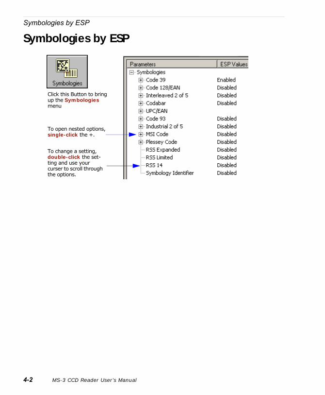
Symbologies by ESP
To change a setting, double-click the set-ting and use your curser to scroll through the options.
To open nested options, single-click the +.
Click this Button to bring up the Symbologies menu
4-2 MS-3 CCD Reader User’s Manual

Chapter 4 Symbologies
Symbologies by Serial Command
Command Title Format
Code 39 <K470, status,check digit status,check digit output sta-tus,unused,unused,minimum symbol length,full ASCII set>
Code 128/EAN <K474, status,unused,minimum symbol length,1,1,unused,application record separator character>
Interleaved 2 of 5 <K472, status,check digit status,check digit output status,symbol length #1,symbol length #2>
Codabar<K471, status,unused,start & stop output status,unused,symbol length status,symbol length,check digit type,check digit status,check digit output status>
UPC/EAN<K489,UPC-A status,UPC-E status,EAN-8 status,EAN-13 status,supplemen-tal status,supplemental 2 status,supplemental 5 status,UPC-A as EAN-13, UPC-E as A,EAN-8 as EAN-13>
Code 93 <K475, status,unused,minimum length>
Industrial 2 of 5 <K488, status,check digit status,check digit output status,format,symbol length #1,symbol length #2>
MSI Code <K486, status,check digit mode,check digit output status,unused,minimum symbol length>
Plessey <K487, status,check digit output status,unused,minimum symbol length>RSS Expanded <K484, status>RSS Limited <K483, status>RSS-14 <K482, status>Symbology ID <K450, 0,symbology identifier status>
MS-3 CCD Reader User’s Manual 4-3
Code 39
Code 39
Code 39 Status
Check Digit Status (Code 39)
Check Digit Output (Code 39)
Usage: Code 39 is considered the standard for non-retail bar code applications.
Definition: An alphanumeric symbol with unique start/stop symbol patterns, com-posed of 9 black and white elements per character, of which 3 are wide.
Serial Cmd: <K470, status,check digit status,check digit output sta-tus,unused,unused,minimum symbol length,full ASCII set>
Default: Enabled Note: This is the only symbol type enabled by default.
Options: 0 = Disabled 1 = Enabled
Serial Cmd: <K470,code 39 status,check digit status,check digit output sta-tus,unused,unused,minimum symbol length,full ASCII set>
Default: Disabled
Options: 0 = Disabled 1 = Enabled
Usage: Check Digit Output Status, added to the symbol, provides additional security.
Definition: When enabled, the check digit character is read and sent along with the symbol data. When disabled, symbol data is sent without the check digit.Note: When in Single symbol mode and Check Digit Output Status and an External or Serial trigger option enabled, an invalid check digit calculation will cause a noread message to be transmitted at the end of the read cycle.
Serial Cmd: <K470, status,check digit status,check digit output sta-tus,unused,unused,minimum symbol length,full ASCII set>
Default: Disabled
Options: 0 = Disabled 1 = Enabled
4-4 MS-3 CCD Reader User’s Manual

Chapter 4 Symbologies
Minimum Symbol Length (Code 39)
Important: When setting Symbol Length to any number other than 0, add 1 to account for a check digit. For example, if your symbol has 3 characters, set Symbol Length to 4.
Full ASCII Set (Code 39)
Usage: Minimum symbol Length helps prevent truncations and increases data integrity by ensuring that a minimum symbol length will be accepted.
Definition: Specifies a number of characters that the reader will recognize, including start and stop and check digit characters. The reader ignores any symbol smaller than the specified length.
Serial Cmd: <K470, status,check digit status,check digit output sta-tus,unused,unused,minimum symbol length,full ASCII set>
Default: 0
Options: 0 to 32
Usage: Must be enabled when reading characters outside the standard character set (0-9, A-Z, etc.)User must know in advance whether or not to use Full ASCII Set option. Since Full ASCII Set requires two symbol words to encode one charac-ter, it is less efficient.
Definition: Standard Code 39 encodes 43 characters; zero through nine, capital “A” through capital “Z”, minus symbol, plus symbol, forward slash, space, dec-imal point, dollar sign and percent symbol. When Full ASCII Set is enabled, the reader can read the full ASCII character set, from 0 to 255.
Serial Cmd: <K470,status,check digit status,check digit output sta-tus,unused,unused,minimum symbol length,full ASCII set>
Default: Disabled
Options: 0 = Disabled 1 = Enabled
MS-3 CCD Reader User’s Manual 4-5
Code 128/EAN
Code 128/EAN
Code 128/EAN Status
Note: Status includes both Code 128 and EAN.Note: Fixed Symbol Length Status must be enabled for Symbol Length to take effect.
Minimum Symbol Length (Code 128/EAN)Note: Minimum Symbol Length is enabled by setting the default to any value other than zero.
Application Record Separator Character (Code 128/EAN)Note: Application Record Separator Character Status is enabled by setting the parameter to any value other than a null.
Usage: Code 128/EAN is useful in applications with tight spots and high security needs.
Definition: A very dense alphanumeric symbology. It encodes all 128 ASCII charac-ters; it is continuous, has variable length, and uses multiple element widths measured edge to edge.
Serial Cmd: <K474, status,unused,minimum symbol length,1,1,unused,application record separator character>
Default: Disabled
Options: 0 = Disabled 1 = Enabled
Usage: Minimum Symbol Length helps prevent truncations and increases data integrity by ensuring that only minimum length symbols will be accepted.
Definition: Specifies a number of characters that the reader will recognize, including start and stop and check digit characters. The reader ignores any symbol smaller than the specified length.
Serial Cmd: <K474, status,unused,minimum symbol length,1,1,unused,application record separator character>
Default: 0 (0 = any length)
Options: 0 to 32
Definition: Allows the user to define an ASCII character as an application record sep-arator.
Serial Cmd: <K474, status,unused,minimum symbol length,1,1,unused,application record separator character>
Default: Null (0x00) (disabled, no separator output)Options: User Defined ASCII character
4-6 MS-3 CCD Reader User’s Manual
Chapter 4 Symbologies
Interleaved 2 of 5
Interleaved 2 of 5 Status
Check Digit Status (Interleaved 2 of 5)
Check Digit Output Status (Interleaved 2 of 5)
Usage: It is has been popular because it is the most dense symbol for printing numeric characters less than 10 characters in length; however Microscan does not recommend this symbology for any new applications because of inherent problems such as truncation.
Definition: A dense, continuous, self-checking, numeric symbology. Characters are paired together so that each character has five elements, two wide and three narrow, representing numbers 0 through 9, with the bars repre-senting the first character and the interleaved spaces representing the second character. (A check digit is highly recommended.) Important: You must set Symbol Length in order to decode I 2/5 sym-bols.
Serial Cmd: <K472, status,check digit status,check digit output status,symbol length #1,symbol length #2>
Default: Disabled
Options: 0 = Disabled 1 = Enabled
Usage: It is typically not used but can be enabled for additional security in appli-cations where the host requires redundant check digit verification.
Definition: An error correcting routine in which the check digit character is added.
Serial Cmd: <K472, status,check digit status,check digit output status,symbol length #1,symbol length #2>
Default: Disabled
Options: 0 = Disabled 1 = Enabled
Definition: When enabled, a check digit character is sent along with the bar symbol data for added data security.
Serial Cmd: <K472, status,check digit status,check digit output status,symbol length #1,symbol length #2>
Default: Disabled
Options: 0 = Disabled 1 = Enabled
MS-3 CCD Reader User’s Manual 4-7
Interleaved 2 of 5
Symbol Length #1 (Interleaved 2 of 5)
Usage: With Industrial 2/5, two symbol lengths can be defined. When using only one symbol length in an application, setting Symbol Length #2 to 0 (zero) to ensure data integrity is recommended.
Definition: Specifies a number of characters that the reader will recognize, including start and stop and check digit characters. The reader ignores any symbol smaller than the specified length. Because Industrial 2/5 is a continuous symbol, it is prone to substitution errors. Hence, a symbol length must be defined and a bar symbol must contain an even number of digits.
Note: If Range Mode is set to Enable, the settings for Symbol Length #1 and Symbol Length #2 will define the range of symbol lengths that can be decoded.
Serial Cmd: <K472, status,check digit status,check digit output status,symbol length #1,symbol length #2>
Default: 6
Options: 0 to 32Rules:Both Symbol Length #1 and Symbol Length #2 must be sent at the same time for the command to take effect.To set for any length, Length #1 and Length #2 must both equal zero.To set for minimum length, both Length #1 and Length #2 must be equal to each other and be any number other than zero.To set for a fixed length, Length #1 and Length #2 must not be equal to each other and must both be greater than zero.
4-8 MS-3 CCD Reader User’s Manual

Chapter 4 Symbologies
Symbol Length #2 (Interleaved 2 of 5)
Important: When setting Symbol Length to any number other than 0, add 1 to account for a reserved space. For example, if your symbol has 3 characters, set Sym-bol Length to 4.
Usage: If using a second symbol, a zero or any even symbol length in the option range may be specified. If not using a second symbol, set Symbol Length #2 to 0 to ensure data integrity.
Definition: Specifies a number of characters that the reader will recognize, including start and stop and check digit characters. The reader ignores any symbol smaller than the specified length.Note: If Range Mode is set to Enable, the settings for Symbol Length #1 and Symbol Length #2 will define the range of symbol lengths that can be decoded.
Serial Cmd: <K472, status,check digit status,check digit output status,symbol length #1,symbol length #2>
Default: 10
Options: 0 to 32Rules:See “Symbol Length #1 (Interleaved 2 of 5)” for rules for saving.
MS-3 CCD Reader User’s Manual 4-9

Codabar
Codabar
Codabar Status
Start & Stop Output Status (Codabar)
Symbol Length Status (Codabar)
Usage: Used in photo-finishing and library applications. Formerly used in some medical applications but not typically used in newer applications.
Definition: Codabar is a 16-character set (0 through 9, and the characters $, :, /, ., +, and –) with start/stop codes and at least two distinctly different bar widths.
Serial Cmd: <K471, status,unused,start & stop match output status,unused,symbol length status,symbol length,check digit status,check digit output status>
Default: Disabled
Options: 0 = Disabled 1 = Enabled
Usage: Used to verify matching.
Definition: Causes the start and stop characters to be transmitted with symbol data.
Serial Cmd: <K471, status,unused,start & stop output status,unused,symbol length status,symbol length,check digit status,check digit output status>
Default: Enabled
Options: 0 = Disabled 1 = Enabled
Usage: Restricting symbol lengths can help prevent truncations and increase data integrity by ensuring that only one or a defined range of symbol lengths will be accepted.
Definition: When set to Fixed, the reader will check the symbol length against the Symbol Length field. When set to Any/Minimum, any length is consid-ered a valid symbol. The following rules apply:
Serial Cmd: <K471, status,unused,start & stop output status,unused,symbol length status,symbol length,check digit status,check digit output status>
Default: Any/Minimum
Options: 0 = Any/Minimum 1 = Fixed
4-10 MS-3 CCD Reader User’s Manual

Chapter 4 Symbologies
Symbol Length (Codabar)
Note: Because of symbology limitations, setting Symbol Length to any number less than four will produce undetermined results.
Check Digit Status (Codabar)
Check Digit Output Status (Codabar)
Definition: Specifies a number of characters that the reader will recognize, including start and stop and check digit characters. The reader ignores any symbol smaller than the specified length.Important Notes:• When setting Symbol Length to any number other than zero, add 2
to account for reserved spaces. For example, if your symbol has 3 characters, set Symbol Length to 5.
• If Symbol Length is set to zero (0) and Symbol Length Status is set to Any/Minimum, all symbol lengths are decoded.
Serial Cmd: <K471, status,unused,start & stop output status,unused,symbol length status, symbol length,check digit status,check digit output status>
Default: 6
Options: 0 to 32 (Zero equals any length.)
Usage: Modulus 16 is used in the photo-finishing market.
Definition: Allows the user to select the check digit type Codabar will use.
Serial Cmd: <K471, status,unused,start & stop output status,unused,symbol length status, symbol length,check digit status,check digit output status>
Default: Disabled
Options: 0 = Disabled 1 = Enable (Modulus 16)
Usage: For additional security a check digit can be added to the symbol.
Definition: When enabled, the check digit character is sent along with the symbol data. When disabled, symbol data is sent without the check digit.
Serial Cmd: <K471, status,unused,start & stop output status,unused,symbol length status, symbol length,check digit type,check digit status,check digit output status>
Default: Disabled
Options: 0 = Disabled 1 = Enabled
MS-3 CCD Reader User’s Manual 4-11

UPC/EAN
UPC/EAN
UPC-A Status
UPC-E Status
EAN-8 Status
EAN-13 Status
Usage: Used primarily in POS application in the retail industry.Definition: UPC (Universal Product Code) is a fixed length numeric, continuous sym-
bology. UPC can have two- or five-digit supplemental symbol data follow-ing the normal symbol. The U.P.C., Version A (U.P.C., A) symbol is used to encode a 12 digit number. The first digit is the number system character, the next five are the manufacturer number, the next five are the product number, and the last digit is the checksum character.
Serial Cmd: <K489,UPC-A status,UPC-E status,EAN-8 status,EAN-13 status,supple-mentals required,supplemental 2 status,supplemental 5 status,UPC-A as EAN-13,UPC-E as A,EAN-8 as EAN-13>
Default: Enabled
Options: 0 = Disabled 1 = Enabled
Serial Cmd: <K489,UPC-A status,UPC-E status,EAN-8 status,EAN-13 status,supple-mentals required,supplemental 2 status,supplemental 5 status,UPC-A as EAN-13,UPC-E as A,EAN-8 as EAN-13>
Default: Enabled
Options: 0 = Disabled 1 = Enabled
Serial Cmd: <K489,UPC-A status,UPC-E status,EAN-8 status,EAN-13 status,supple-mentals required,supplemental 2 status,supplemental 5 status,UPC-A as EAN-13,UPC-E as A,EAN-8 as EAN-13>
Default: Enabled
Options: 0 = Disabled 1 = Enabled
Serial Cmd: <K489,UPC-A status,UPC-E status,EAN-8 status,EAN-13 status,supple-mentals required,supplemental 2 status,supplemental 5 status, UPC-A as EAN-13, UPC-E as A,EAN-8 as EAN-13>
Default: Enabled
Options: 0 = Disabled 1 = Enabled
4-12 MS-3 CCD Reader User’s Manual

Chapter 4 Symbologies
Supplementals
Required (UPC/EAN)
Supplemental 2 Status
Supplemental 5 Status
Usage: Reads Supplementals typically used in publications and documentation.Definition: A supplemental is a 2 or 5 digit symbol appended to the main symbol.
When set to Enabled (Required), the reader reads supplemental symbol data that has been appended to the standard UPC or EAN codes.
Serial Cmd: <K489,UPC-A status,UPC-E status,EAN-8 status,EAN-13 status,supple-mentals required,supplemental 2 status,supplemental 5 status, UPC-A as EAN-13, UPC-E as A,EAN-8 as EAN-13>
Default: Disabled (Not Required)Options: 0 = Not required, but output if decoded
1 = Enabled (Required)
Default: DisabledSerial Cmd: <K489,UPC-A status,UPC-E status,EAN-8 status,EAN-13 status,supple-
mentals required,supplemental 2 status,supplemental 5 status, UPC-A as EAN-13, UPC-E as A,EAN-8 as EAN-13>
Options: 0 = Disabled 1 = Enabled
Default: DisabledSerial Cmd: <K489,UPC-A status,UPC-E status,EAN-8 status,EAN-13 status,supple-
mentals required,supplemental 2 status,supplemental 5 status, UPC-A as EAN-13,UPC-E as A,EAN-8 as EAN-13>
Options: 0 = Disabled 1 = Enabled
MS-3 CCD Reader User’s Manual 4-13
UPC/EAN
Output Format
UPC-A as EAN-13
UPC-E as UPC-A
EAN-8 as EAN-13
Definition UPC-A will be transmitted as EAN-13Serial Cmd: <K489,UPC-A status,UPC-E status,EAN-8 status,EAN-13 status,supple-
mentals required,supplemental 2 status,supplemental 5 status, UPC-A as EAN-13,UPC-E as A,EAN-8 as EAN-13>
Default: Enabled
Options: 0 = Disabled 1 = Enabled
Definition UPC-E will be transmitted as UPC-ASerial Cmd: <K489,UPC-A status,UPC-E status,EAN-8 status,EAN-13 status,supple-
mentals required,supplemental 2 status,supplemental 5 status, UPC-A as EAN-13 UPC-E as A,EAN-8 as EAN-13>
Default: Disabled
Options: 0 = Disabled 1 = Enabled
Definition EAN-8 will be transmitted as EAN-13Serial Cmd: <K489,UPC-A status,UPC-E status,EAN-8 status,EAN-13 status,supple-
mentals required,supplemental 2 status,supplemental 5 status, UPC-A as EAN-13,UPC-E as A,EAN-8 as EAN-13>
Default: Disabled
Options: 0 = Disabled 1 = Enabled
4-14 MS-3 CCD Reader User’s Manual
Chapter 4 Symbologies
Code 93
Code 93 Status
Minimum Symbol Length (Code 93)
Usage: Used occasionally in clinical industry.Definition: Code 93 is a variable length, continuous symbology employing four ele-
ment widths. Each Code 93 character has nine modules that may be either black or white. Each character contains three bars and three spaces.
Serial Cmd: <K475, status,unused,minimum length>Default: Disabled
Options: 0 = Disabled 1 = Enabled
Usage: Minimum Symbol Length helps prevent truncations and increases data integrity by ensuring that a minimum symbol length will be accepted.
Definition: Specifies the minimum number of characters that the reader will recog-nize (this does not include start and stop and check digit characters). The reader ignores any symbol smaller than the specified length.Important: When setting Symbol Length to any number other than zero, add 1 to account for a reserved space. For example, if your symbol has 3 characters, set Symbol Length to 4.
Serial Cmd: <K475, status,unused,minimum symbol length>Default: 10Options: 0 to 32
MS-3 CCD Reader User’s Manual 4-15

Industrial 2 of 5
Industrial 2 of 5
Industrial 2 of 5 Status
Check Digit Status (Industrial 2 of 5)
Check Digit Output Status (Industrial 2 of 5)
Usage: Also called “Standard 2 of 5,” it has been used widely in the photofinish-ing and warehouse sorting industries, as well as sequentially numbering airline tickets. Microscan does not recommend this symbology for any new applications because of inherent problems such as truncation.
Definition: A non-interleaved, low-density, continuous, self-checking numeric sym-bology that does not require a checksum. The encoding method is essentially the same as Interleaved 2 of 5 except that with Industrial spaces are fixed width and used only to separate the bars. Interleaved 2 of 5 allows information to be encoded in both the bars and spaces.(A check digit is highly recommended.) Important: You must set Symbol Length in order to decode Industrial 2/5 symbols.
Serial Cmd: <K488, status,check digit status,check digit output status,format,sym-bol length #1,symbol length #2>
Default: Disabled
Options: 0 = Disabled 1 = Enabled
Usage: It is typically not used but can be enabled for additional security in appli-cations where the host requires redundant check digit verification.
Definition: An error correcting routine in which the check digit character is added.
Serial Cmd: <K488, status,check digit status,check digit output status,format, symbol length #1,symbol length #2>
Default: Disabled
Definition: When enabled, a check digit character is sent along with the bar symbol data for added data security.
Serial Cmd: <K488, status,check digit status,check digit output status,format, symbol length #1,symbol length #2>
Default: Disabled
Options: 0 = Disabled 1 = Enabled
4-16 MS-3 CCD Reader User’s Manual

Chapter 4 Symbologies
Format (Industrial 2 of 5)
Symbol Length #1 (Industrial 2 of 5)
Definition: Sets the number of start and stop characters
Serial Cmd: <K488, status,check digit status,check digit output status,format, sym-bol length #1,symbol length #2>
Default: 3 start/3 stop
Options: 0 = 3 start/3 stop 1 = 2 start/2 stop
Usage: With Industrial 2/5, two symbol lengths can be defined. When using only one symbol length in an application, setting Symbol Length #2 to 0 (zero) to ensure data integrity is recommended.
Definition: Specifies a number of characters that the reader will recognize, including a check digit character. Allows user to define the symbol length as any length, a minimum length, or a fixed length.
Serial Cmd: <K488, status,check digit status,check digit output status,format,sym-bol length #1,symbol length #2>
Serial Cmd: <K472, status,check digit status,check digit output status,format, sym-bol length #1,symbol length #2>
Default: 10
Options: 0 to 32Rules:• Both Symbol Length #1 and Symbol Length #2 must be saved at
the same time for the command to take effect.• To set for any length, Length #1 and Length #2 must both equal
zero.• To set for minimum length, both Symbol Length #1 and Symbol
Length #2 must be equal to each other and be any number other than zero.
• To set fixed lengths, Length #1 and Length #2 must not be equal to each other and either one greater than zero.
MS-3 CCD Reader User’s Manual 4-17

Symbol Length #2 (Industrial 2 of 5)
Symbol Length #2 (Industrial 2 of 5)
Usage: If using a second symbol, a zero or any symbol length from 0 to 32 may be specified. If not using a second symbol, set Symbol Length #2 to 0 to ensure data integrity.
Definition: Specifies a number of characters that the reader will recognize, including a check digit character. Allows user to define a second symbol length for Industrial 2/5.
Serial Cmd: <K488, status,check digit status,check digit output status,format,symbol length #1,symbol length #2>
Default: 6
Options: 0 to 32See “Symbol Length #1 (Industrial 2 of 5)”for rules for saving.
4-18 MS-3 CCD Reader User’s Manual

Chapter 4 Symbologies
MSI Code
MSI Status
Check Digit Mode (MSI Code)
Check Digit Output Status (MSI Code)
Minimum Symbol Length (MSI Code)
Usage: Used in retail and inventory markets.Definition: A variation of Plessey, MSI is a numeric, continuous code, with each char-
acter consisting of four bits in a binary format.
Serial Cmd: <K486, status,check digit mode,check digit output status,unused,mini-mum symbol length>
Default: Disabled
Options: 0 = Disabled 1 = Enabled
Serial Cmd: <K486, status,check digit mode,check digit output status,unused,mini-mum symbol length>
Default: Mod10
Serial Cmd: <K486, status,check digit mode,check digit output sta-tus,unused,minimum symbol length>
Default: Enabled
Options: 0 = Disabled 1 = Enabled
Definition: Specifies a number of characters that the reader will recognize, including a check digit character.
Serial Cmd: <K486, status,check digit mode,check digit output status,unused,mini-mum symbol length>
Default: 6Options: 0 to 32
Zero equals any length. 1 through 32 sets a minimum length.
MS-3 CCD Reader User’s Manual 4-19

Plessey Code
Plessey Code
Plessey Status
Check Digit Output Status (Plessey Code)
Minimum Symbol Length (Plessey Code)
Usage: First developed in March 1971, it has been used extensively in libraries, retail, production, and stock control.
Definition: Plessey Code consists of pairs of wide/narrow bars that represent 1s and 0s which, taken in units of 12, define hexidecimal characters.
Serial Cmd: <K487, status,check digit output status,unused,minimum symbol length>
Default: Disabled
Options: 0 = Disabled 1 = Enabled
Serial Cmd: <K487, status,check digit output status,unused,minimum symbol length>
Default: Disabled
Options: 0 = Disabled 1 = Enabled
Definition: Specifies a number of characters that the reader will recognize, including a check digit character.
Serial Cmd: <K487, status,check digit output status,unused,minimum symbol length>
Default: 0
Options: 0 to 32
4-20 MS-3 CCD Reader User’s Manual

Chapter 4 Symbologies
RSS Expanded
Usage: Used to encode primary and supplementary data in retail point-of-sale and other applications.
Definition: RSS Expanded is a variable length symbology that can encode supple-mentary information in addition to the 14-digit EAN.UCC item identifica-tion number and is capable of encoding up to 74 numeric or 41 alphabetic characters.
Serial Cmd: <K484, status>
Default: Disabled
Options: 0 = Disabled 1 = Enabled
MS-3 CCD Reader User’s Manual 4-21

RSS Limited
RSS Limited
Usage: RSS Limited is designed to be read by laser and CCD readers. It is not recommended for omnidirectional slot readers.
Definition: Encodes a smaller 14-digit symbol (74 modules wide) that is not omnidi-rectional.
Serial Cmd: <K483, status>
Default: Disabled
Options: 0 = Disabled 1 = Enabled
4-22 MS-3 CCD Reader User’s Manual
Chapter 4 Symbologies
RSS-14
Usage: Used in the grocery retail and prescription drug industries where full 14-digit EAN.UCC item identification may be needed.
Definition: RSS-14 (Reduced Space Symbology) is a fixed length symbology that encodes 14-digits, including a 1 digit indicator digit and is 96 modules wide. It can be stacked into two rows, read omnidirectional if printed in full height, or not if height-truncated for small marking.
Serial Cmd: <K482, status>
Default: Disabled
Options: 0 = Disabled 1 = Enabled
MS-3 CCD Reader User’s Manual 4-23
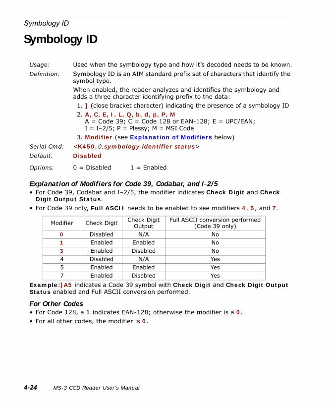
Symbology ID
Symbology ID
Explanation of Modifiers for Code 39, Codabar, and I–2/5• For Code 39, Codabar and I–2/5, the modifier indicates Check Digit and Check
Digit Output Status. • For Code 39 only, Full ASCII needs to be enabled to see modifiers 4, 5, and 7.
Example:]A5 indicates a Code 39 symbol with Check Digit and Check Digit Output Status enabled and Full ASCII conversion performed.
For Other Codes• For Code 128, a 1 indicates EAN-128; otherwise the modifier is a 0.• For all other codes, the modifier is 0.
Usage: Used when the symbology type and how it’s decoded needs to be known.
Definition: Symbology ID is an AIM standard prefix set of characters that identify the symbol type.When enabled, the reader analyzes and identifies the symbology and adds a three character identifying prefix to the data:1. ] (close bracket character) indicating the presence of a symbology ID2. A, C, E, I, L, Q, b, d, p, P, M
A = Code 39; C = Code 128 or EAN-128; E = UPC/EAN; I = I–2/5; P = Plessy; M = MSI Code
3. Modifier (see Explanation of Modifiers below)
Serial Cmd: <K450, 0,symbology identifier status>
Default: Disabled
Options: 0 = Disabled 1 = Enabled
Modifier Check Digit Check Digit Output
Full ASCII conversion performed (Code 39 only)
0 Disabled N/A No1 Enabled Enabled No3 Enabled Disabled No4 Disabled N/A Yes5 Enabled Enabled Yes7 Enabled Disabled Yes
4-24 MS-3 CCD Reader User’s Manual
Utilities
Chapter Contents
Utility commands are generally commands that are performed during reader operations to perform miscellaneous operations on reader hardware. Serial utility commands are not prefaced with a “K” and a numeric code. They can be entered from within any ter-minal program or from within ESP in the Terminal window.Note on Serial Com-mands: To preserve continuity with other Microscan products, some serial configuration commands may include 0s (zeros) or 1s as placeholders. In order for a these commands to be implemented, the placeholder values or commas must be included.
Chapter
5
Utilities by ESP Menu ..............................................................................5-2Summary of Utilities Commands..............................................................5-2Firmware..................................................................................................5-3Device Control .........................................................................................5-4Reader Status Requests..........................................................................5-5
MS-3 CCD Reader User’s Manual 5-1
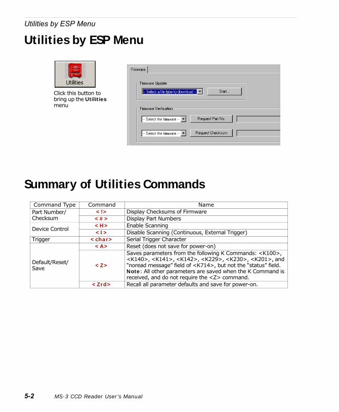
Utilities by ESP Menu
Utilities by ESP Menu
Summary of Utilities CommandsCommand Type Command NamePart Number/Checksum
<!> Display Checksums of Firmware<#> Display Part Numbers
Device Control<H> Enable Scanning<I> Disable Scanning (Continuous, External Trigger)
Trigger <char> Serial Trigger Character
Default/Reset/Save
<A> Reset (does not save for power-on)
<Z>
Saves parameters from the following K Commands: <K100>, <K140>, <K141>, <K142>, <K229>, <K230>, <K201>, and “noread message” field of <K714>, but not the “status” field.Note: All other parameters are saved when the K Command is received, and do not require the <Z> command.
<Zrd> Recall all parameter defaults and save for power-on.
Click this button to bring up the Utilities menu
5-2 MS-3 CCD Reader User’s Manual
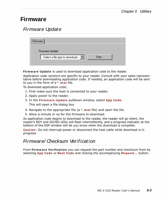
Chapter 5 Utilities
Firmware
Firmware Update
Firmware Update is used to download application code to the reader. Application code versions are specific to your reader. Consult with your sales represen-tative before downloading application code. If needed, an application code will be sent to you in the form of a *.mot file.To download application code:1. First make sure the host is connected to your reader.2. Apply power to the reader.3. In the Firmware Update pulldown window, select App Code.
This will open a file dialog box.
4. Navigate to the appropriate file (a *.mot file) and open the file.5. Allow a minute or so for the firmware to download.
As application code begins to download to the reader, the reader will go silent, the reader’s RDY and GD/RD LEDs will flash intermittently, and a progress indicator at the bottom of the ESP window will let you know when the download is complete.Caution: Do not interrupt power or disconnect the host cable while download is in progress.
Firmware/Checksum Verification
From Firmware Verification you can request the part number and checksum from by selecting App Code or Boot Code and clicking the accompanying Request... button.
MS-3 CCD Reader User’s Manual 5-3
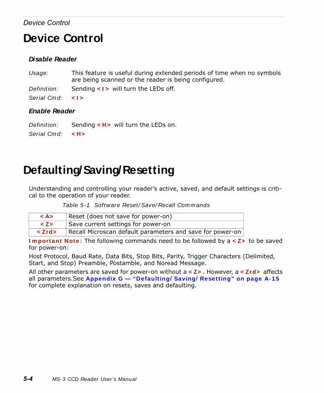
Device Control
Device Control
Disable Reader
Enable Reader
Defaulting/Saving/ResettingUnderstanding and controlling your reader’s active, saved, and default settings is criti-cal to the operation of your reader.
Important Note: The following commands need to be followed by a <Z> to be saved for power-on:Host Protocol, Baud Rate, Data Bits, Stop Bits, Parity, Trigger Characters (Delimited, Start, and Stop) Preamble, Postamble, and Noread Message. All other parameters are saved for power-on without a <Z>. However, a <Zrd> affects all parameters.See Appendix G — “Defaulting/Saving/Resetting” on page A-15 for complete explanation on resets, saves and defaulting.
Usage: This feature is useful during extended periods of time when no symbols are being scanned or the reader is being configured.
Definition: Sending <I> will turn the LEDs off.
Serial Cmd: <I>
Definition: Sending <H> will turn the LEDs on.
Serial Cmd: <H>
Table 5-1 Software Reset/Save/Recall Commands
<A> Reset (does not save for power-on)<Z> Save current settings for power-on
<Zrd> Recall Microscan default parameters and save for power-on
5-4 MS-3 CCD Reader User’s Manual
Chapter 5 Utilities
Reader Status Requests
<K?> Configuration Command StatusReturns the current status of all configuration commands.
MS-3 CCD Reader User’s Manual 5-5

Reader Status Requests
5-6 MS-3 CCD Reader User’s Manual
Terminal Mode
Chapter Contents
This section describes the terminal window and macro functions.
Note: The characters NULL <> and , can only be entered through embedded menus, not through ESP or serial commands.
Chapter
6
Terminal Window.........................................................................................6-2Find Function...............................................................................................6-3Macros.........................................................................................................6-4Terminal Window Functions ........................................................................6-5
MS-3 CCD Reader User’s Manual 6-1

Terminal Window
Terminal Window
To use the terminal mode, click on the Terminal button.
You will see the following window:
The terminal screen allows you to enter serial commands (in red) from the macro box, by copying, or directly from your keyboard.The terminal screen also displays bar code data or information from the reader (in blue).You can also right click in the terminal screen to bring up a handy option box.
Clear screen
Copy, paste, and save
Macro List on this bar
Type in text here to find in terminal window
Terminal screen
Figure 6-1 Terminal Window
Click on Macros arrow to Add Macro, Remove Macro or Edit Macro
Click on Macro to Run
6-2 MS-3 CCD Reader User’s Manual
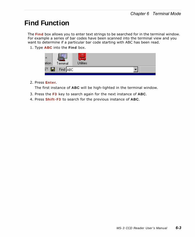
Chapter 6 Terminal Mode
Find FunctionThe Find box allows you to enter text strings to be searched for in the terminal window. For example a series of bar codes have been scanned into the terminal view and you want to determine if a particular bar code starting with ABC has been read. 1. Type ABC into the Find box.
2. Press Enter. The first instance of ABC will be high-lighted in the terminal window.
3. Press the F3 key to search again for the next instance of ABC.4. Press Shift-F3 to search for the previous instance of ABC.
MS-3 CCD Reader User’s Manual 6-3
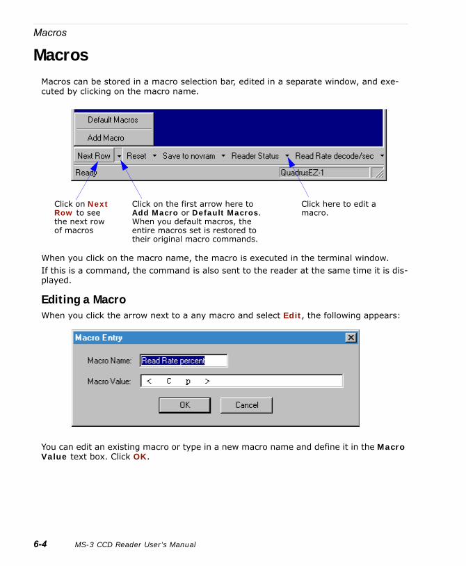
Macros
MacrosMacros can be stored in a macro selection bar, edited in a separate window, and exe-cuted by clicking on the macro name.
When you click on the macro name, the macro is executed in the terminal window. If this is a command, the command is also sent to the reader at the same time it is dis-played.
Editing a MacroWhen you click the arrow next to a any macro and select Edit, the following appears:
You can edit an existing macro or type in a new macro name and define it in the Macro Value text box. Click OK.
Click on Next Row to see the next row of macros
Click on the first arrow here to Add Macro or Default Macros.When you default macros, the entire macros set is restored to their original macro commands.
Click here to edit a macro.
6-4 MS-3 CCD Reader User’s Manual
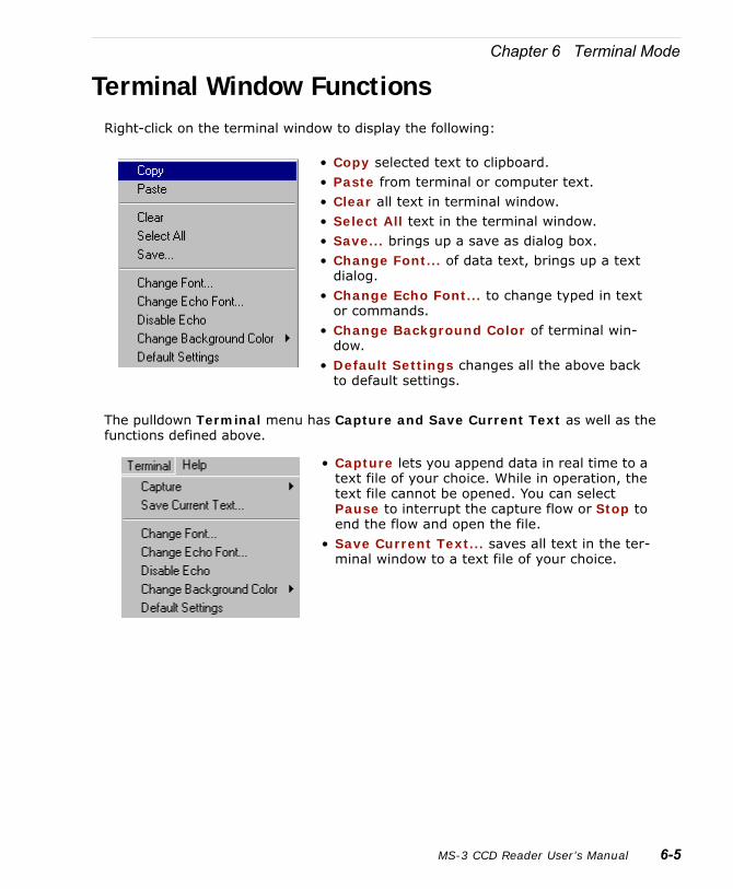
Chapter 6 Terminal Mode
Terminal Window FunctionsRight-click on the terminal window to display the following:
The pulldown Terminal menu has Capture and Save Current Text as well as the functions defined above.
• Copy selected text to clipboard.• Paste from terminal or computer text.• Clear all text in terminal window.• Select All text in the terminal window.• Save... brings up a save as dialog box.• Change Font... of data text, brings up a text
dialog.• Change Echo Font... to change typed in text
or commands.• Change Background Color of terminal win-
dow.• Default Settings changes all the above back
to default settings.
• Capture lets you append data in real time to a text file of your choice. While in operation, the text file cannot be opened. You can select Pause to interrupt the capture flow or Stop to end the flow and open the file.
• Save Current Text... saves all text in the ter-minal window to a text file of your choice.
MS-3 CCD Reader User’s Manual 6-5

Terminal Window Functions
6-6 MS-3 CCD Reader User’s Manual

Appendices
Chapter ContentsAppendix A General Specifications .........................................................A-2Appendix B Electrical Specifications .......................................................A-4Appendix C Connectivity .........................................................................A-5Appendix D Serial Configuration Commands ........................................A-10Appendix E Serial Command Format ....................................................A-12Appendix F ASCII Table ........................................................................A-14Appendix G Defaulting/Saving/Resetting ..............................................A-15Appendix H Object Detector ..................................................................A-17Appendix I Formulas for Number of Decodes .......................................A-18Appendix J Operational Tips .................................................................A-20Appendix K Glossary of Terms..............................................................A-21
MS-3 CCD Reader User’s Manual A-1

General Specifications
s
Appendix A — General SpecificationsMechanical
Height: 0.85” (21.6 mm)Width: 1.75” (44.5 mm)Depth: 1.75” (44.5 mm)Weight: 2.0 oz. (57 g)
EnvironmentalEnclosure rating: IP54, category 2Operating temperature: –30° to 60° C (–22° to 140° F)Humidity: Up to 90% (non-condensing)Operating life: 40,000 hours at 25° CAmbient light: Works in any lighting condi-tions, from 0 to 100,000 lux
CE MARKGeneral immunity for light industry:EN 55024: 1998 ITE Immunity StandardRadiated and Conducted Emissions of ITE equipment: EN 55022:98, ITE disturbances class A.
OpticsSlotted CCD
Scanning ParametersScan rate (decoded mode): 270 scans per second, auto-adaptiveMinimum X dimension: down to 0.05 mm (2 mil) on Code 39Depth of field: 0 to 49.2 cm (19.4”)Bar code width: up to 18 cm (7”) on 0.3 mm (12 mil) resolution codePrint contrast: down to 20%Scan width angle: 48° nominalPitch: ±50°; Skew: ±40°Symbol contrast: 25% min. @ 650 nM
Connector3 ft. (914 mm) cable terminated with 15-pin D-sub socket connector
CommunicationsRS-232 TTL, Wedge
.85" (21.6 mm)
2X M3 x 0.55.3 mm depth
.31"(7.8 mm)
Beam
1.75" (44.5 mm)
1.41"(35.8 mm)
1.75"(44.5 mm)
.90"(22.8 mm)
.22" (5.6 mm)
�!��"
#��!�$$%
!��"#��!�$$%
�!��"#��!&$$%
!��"#��!�$$%
!&�"#��!�$$%
�'�(�)�!��$$�(* +,-.�
�!��"#��!�$$%
����
!/�"#��!/�$$%
��0
1���,$�����
����
Figure A-1 MS-3 CCD Dimensions
Figure A-2 MS-3 CCD Right Angle Dimension
A-2 MS-3 CCD Reader User’s Manual

Appendices
Read Ranges
Safety CertificationsFCC, UL/cUL, CE, BSMIISO 9001:2000 Certification No. 03-1212Product specifications are given for typical performance at 23°C (74°F) using grade A sym-bols. Some performance characteristics may vary at high temperatures or other environmental extremes.© 2006 Microscan Systems, Inc. Specifications subject to change.
���! �
� �������$
��
��
�$ �!�
�
�
�
��
��
��
��
��
��
2 �
!����"!�/��$$
!���"!����$$
!���"!��&�$$
����$
��! �� � �
��
�
�
�
�
�
�
�!�$
2 �
� �
!���"!����$$ !���"
!��&�$$
!���"!����$$
Low Density RangesHigh Density Ranges
Figure A-3 MS-3 CCD Read Ranges
Note: The above graphs are not drawn to the same scale.
MS-3 CCD Reader User’s Manual A-3
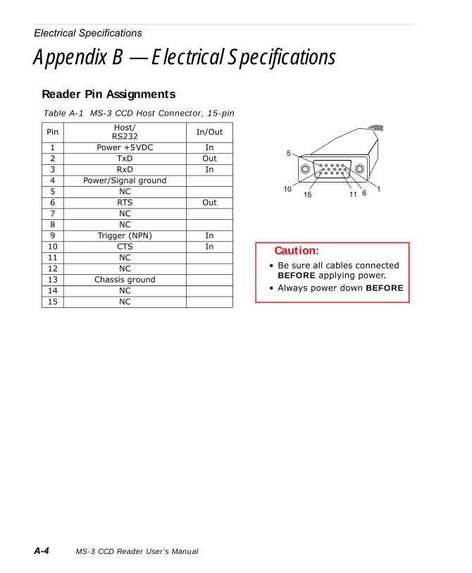
Electrical Specifications
Appendix B — Electrical SpecificationsReader Pin AssignmentsTable A-1 MS-3 CCD Host Connector, 15-pin
Pin Host/RS232 In/Out
1 Power +5 VDC In2 TxD Out3 RxD In4 Power/Signal ground5 NC6 RTS Out7 NC8 NC9 Trigger (NPN) In10 CTS In11 NC12 NC13 Chassis ground14 NC15 NC
1
5
1015 11 6
Caution:• Be sure all cables connected
BEFORE applying power.• Always power down BEFORE
A-4 MS-3 CCD Reader User’s Manual
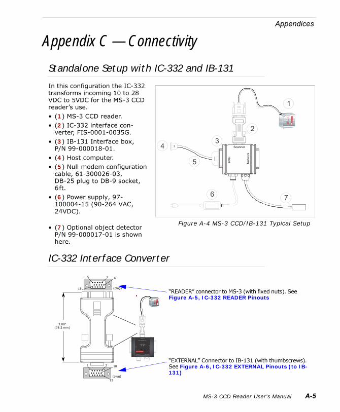
Appendices
Appendix C — ConnectivityStandalone Setup with IC-332 and IB-131
In this configuration the IC-332 transforms incoming 10 to 28 VDC to 5VDC for the MS-3 CCDreader’s use.• (1) MS-3 CCD reader.• (2) IC-332 interface con-
verter, FIS-0001-0035G.• (3) IB-131 Interface box,
P/N 99-000018-01.• (4) Host computer.• (5) Null modem configuration
cable, 61-300026-03, DB-25 plug to DB-9 socket, 6 ft.
• (6) Power supply, 97- 100004-15 (90-264 VAC, 24VDC).
• (7) Optional object detector P/N 99-000017-01 is shown here.
IC-332 Interface Converter
4
1
2
3
7
5
Scanner
Net
wor
k
Host
6
Figure A-4 MS-3 CCD/IB-131 Typical Setup
��
������
��
��
������
�
��
�� ��� ������
“READER” connector to MS-3 (with fixed nuts). See Figure A-5, IC-332 READER Pinouts
“EXTERNAL” Connector to IB-131 (with thumbscrews).See Figure A-6, IC-332 EXTERNAL Pinouts (to IB-131)
MS-3 CCD Reader User’s Manual A-5
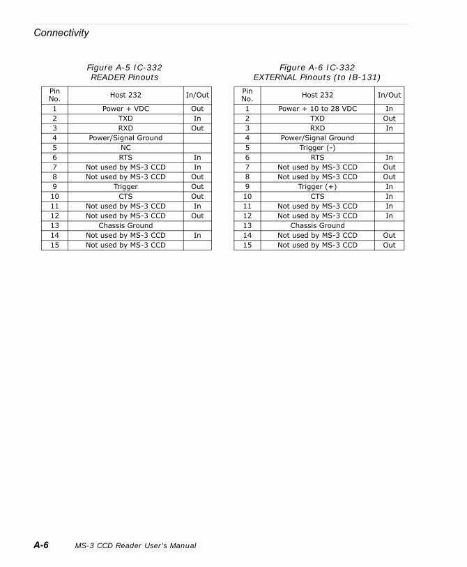
Connectivity
Figure A-5 IC-332 READER Pinouts
Figure A-6 IC-332 EXTERNAL Pinouts (to IB-131)
Pin No. Host 232 In/Out
1 Power + VDC Out2 TXD In3 RXD Out4 Power/Signal Ground5 NC6 RTS In7 Not used by MS-3 CCD In8 Not used by MS-3 CCD Out9 Trigger Out10 CTS Out11 Not used by MS-3 CCD In12 Not used by MS-3 CCD Out13 Chassis Ground14 Not used by MS-3 CCD In15 Not used by MS-3 CCD
Pin No. Host 232 In/Out
1 Power + 10 to 28 VDC In2 TXD Out3 RXD In4 Power/Signal Ground5 Trigger (-)6 RTS In7 Not used by MS-3 CCD Out8 Not used by MS-3 CCD Out9 Trigger (+) In10 CTS In11 Not used by MS-3 CCD In12 Not used by MS-3 CCD In13 Chassis Ground14 Not used by MS-3 CCD Out15 Not used by MS-3 CCD Out
A-6 MS-3 CCD Reader User’s Manual
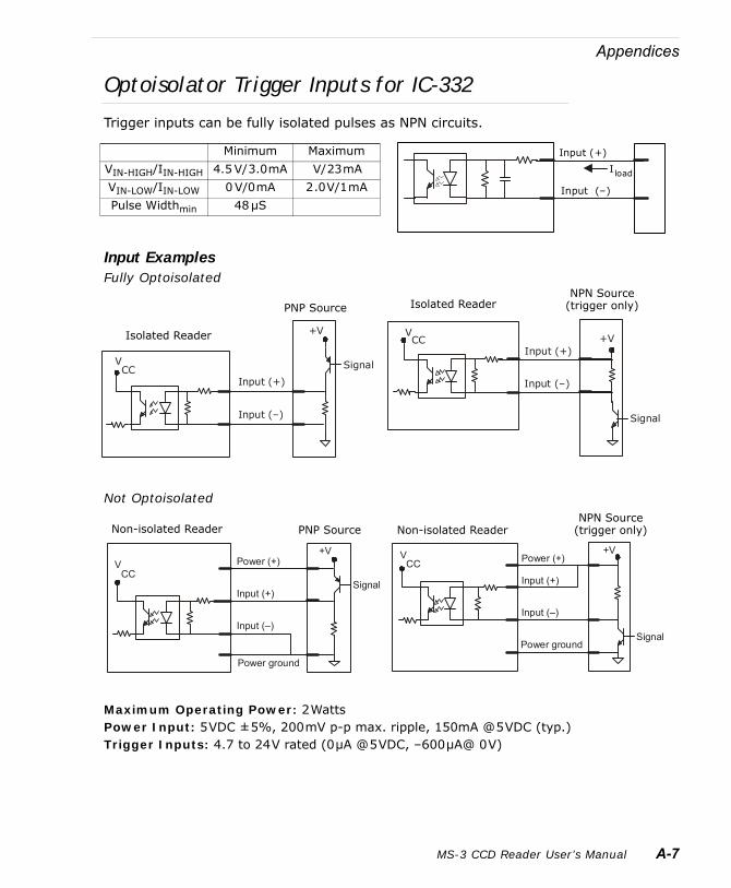
Appendices
Optoisolator Trigger Inputs for IC-332
Trigger inputs can be fully isolated pulses as NPN circuits.
Input ExamplesFully Optoisolated
Not Optoisolated
Maximum Operating Power: 2 WattsPower Input: 5 VDC ± 5%, 200 mV p-p max. ripple, 150mA @ 5 VDC (typ.)Trigger Inputs: 4.7 to 24 V rated (0 µA @ 5 VDC, –600 µA@ 0 V)
Input (+)
Input (–)
I load
Minimum Maximum
VIN-HIGH/IIN-HIGH 4.5 V/ 3.0 mA V/ 23 mA
VIN-LOW/IIN-LOW 0 V/0 mA 2 .0 V/1 mA
Pulse Widthmin 48 µS
Isolated ReaderPNP Source
+V
Signal
VCC
Input (–)
Input (+)
+V
SignalVCC
Input (+)
Input (–)
NPN Source (trigger only)
Isolated Reader
Non-isolated Reader Non-isolated ReaderNPN Source
(trigger only)PNP Source
Signal
+VVCC
Input (–)
Input (+)
Power (+)
Power ground
+V
Signal
VCC
Power ground
Input (–)
Input (+)
Power (+)
MS-3 CCD Reader User’s Manual A-7
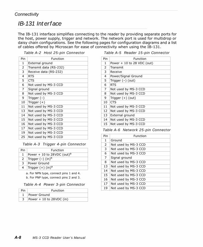
Connectivity
IB-131 Interface
The IB-131 interface simplifies connecting to the reader by providing separate ports for the host, power supply, trigger and network. The network port is used for multidrop or daisy chain configurations. See the following pages for configuration diagrams and a list of cables offered by Microscan for ease of connectivity when using the IB-131.
Table A-2 Host 25-pin Connector
Table A-3 Trigger 4-pin Connector
Table A-4 Power 3-pin Connector
Table A-5 Reader 15-pin Connector
Table A-6 Network 25-pin Connector
Pin Function1 External ground2 Transmit data (RS-232)3 Receive data (RS-232) 4 RTS5 CTS6 Not used by MS-3 CCD7 Signal ground8 Not used by MS-3 CCD9 Trigger (–)10 Trigger (+)11 Not used by MS-3 CCD13 Not used by MS-3 CCD14 Not used by MS-3 CCD15 Not used by MS-3 CCD16 Not used by MS-3 CCD17 Not used by MS-3 CCD19 Not used by MS-3 CCD25 Not used by MS-3 CCD
Pin Function1 Power + 10 to 28 VDC (out)a
a. For NPN type, connect pins 1 and 4.
2 Trigger (–) (in)b
b. For PNP type, connect pins 2 and 3.
3 Power Ground4 Trigger (+) (in)a
Pin Function1 Power Ground3 Power + 10 to 28 VDC (in)
Pin Function1 Power + 10 to 28 VDC (out)2 Transmit 3 Receive 4 Power/Signal Ground5 Trigger (–) (out)6 RTS7 Not used by MS-3 CCD8 Not used by MS-3 CCD9 Trigger (+) (out)10 CTS11 Not used by MS-3 CCD12 Not used by MS-3 CCD13 External ground14 Not used by MS-3 CCD15 Not used by MS-3 CCD
Pin Function1 Ground2 Not used by MS-3 CCD3 Not used by MS-3 CCD6 Not used by MS-3 CCD7 Signal ground8 Not used by MS-3 CCD13 Not used by MS-3 CCD14 Not used by MS-3 CCD15 Not used by MS-3 CCD16 Not used by MS-3 CCD17 Not used by MS-3 CCD19 Not used by MS-3 CCD
A-8 MS-3 CCD Reader User’s Manual

Appendices
Electrical:Voltage Input: Regulated +10 to 28 VDC
Cabling:RS-232 Cable: 61-300026-03Multidrop Cable: 61-100030-03Daisy Chain Cable: 61-100029-03
Mechanical:Length: 3.2 in. (8.13 cm)Width: 3.15 in. (8 cm)Height: 0.75 in. (1.9 cm)
�������� ���
����� � ���
�������� ������ ����������� ���� ���
�������
��!��"
#�!��
�����$
%������
&���
���' ��(� ��� )����� ������
����� ��� ���
Figure A-7 IB-131 Mechanical
MS-3 CCD Reader User’s Manual A-9
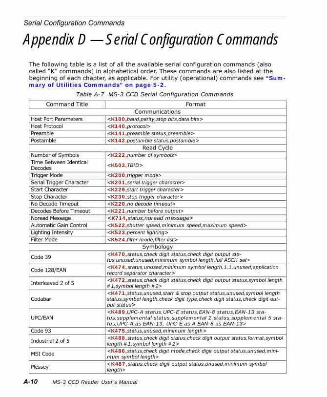
Serial Configuration Commands
Appendix D — Serial Configuration CommandsThe following table is a list of all the available serial configuration commands (also called “K” commands) in alphabetical order. These commands are also listed at the beginning of each chapter, as applicable. For utility (operational) commands see “Sum-mary of Utilities Commands” on page 5-2.
Table A-7 MS-3 CCD Serial Configuration Commands
Command Title FormatCommunications
Host Port Parameters <K100,baud,parity,stop bits,data bits>Host Protocol <K140, protocol>Preamble <K141,preamble status,preamble>Postamble <K142,postamble status,postamble>
Read CycleNumber of Symbols <K222, number of symbols>Time Between Identical Decodes <K503,TBID>
Trigger Mode <K200,trigger mode>Serial Trigger Character <K201, serial trigger character>Start Character <K229,start trigger character>Stop Character <K230, stop trigger character>No Decode Timeout <K220, no decode timeout>Decodes Before Timeout <K221, number before output>Noread Message <K714, status,noread message>Automatic Gain Control <K522,shutter speed,minimum speed,maximum speed>Lighting Intensity <K523,percent lighting>Filter Mode <K524,filter mode,filter list>
Symbology
Code 39 <K470, status,check digit status,check digit output sta-tus,unused,unused,minimum symbol length,full ASCII set>
Code 128/EAN <K474, status,unused,minimum symbol length,1,1,unused,application record separator character>
Interleaved 2 of 5 <K472, status,check digit status,check digit output status,symbol length #1,symbol length #2>
Codabar<K471, status,unused,start & stop output status,unused,symbol length status,symbol length,check digit type,check digit status,check digit out-put status>
UPC/EAN<K489,UPC-A status,UPC-E status,EAN-8 status,EAN-13 sta-tus,supplemental status,supplemental 2 status,supplemental 5 sta-tus,UPC-A as EAN-13, UPC-E as A,EAN-8 as EAN-13>
Code 93 <K475, status,unused,minimum length>
Industrial 2 of 5 <K488, status,check digit status,check digit output status,format,symbol length #1,symbol length #2>
MSI Code <K486, status,check digit mode,check digit output status,unused,mini-mum symbol length>
Plessey <K487, status,check digit output status,unused,minimum symbol length>
A-10 MS-3 CCD Reader User’s Manual
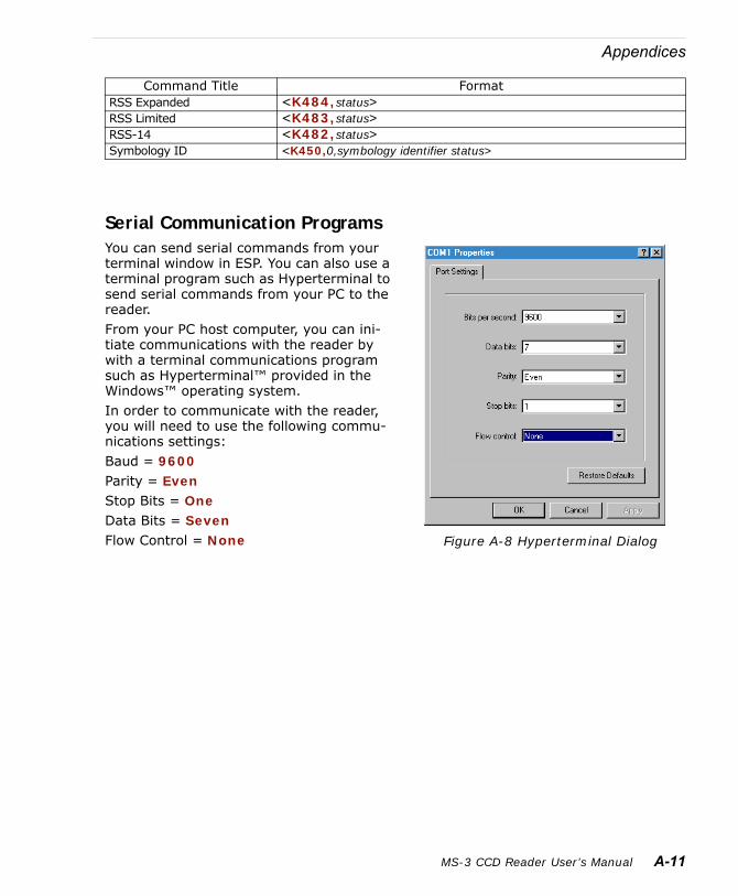
Appendices
Serial Communication ProgramsYou can send serial commands from your terminal window in ESP. You can also use a terminal program such as Hyperterminal to send serial commands from your PC to the reader.From your PC host computer, you can ini-tiate communications with the reader by with a terminal communications program such as Hyperterminal™ provided in the Windows™ operating system.In order to communicate with the reader, you will need to use the following commu-nications settings:Baud = 9600Parity = EvenStop Bits = OneData Bits = SevenFlow Control = None
RSS Expanded <K484, status>RSS Limited <K483, status>RSS-14 <K482, status>Symbology ID <K450, 0,symbology identifier status>
Command Title Format
Figure A-8 Hyperterminal Dialog
MS-3 CCD Reader User’s Manual A-11
Serial Command Format
Appendix E — Serial Command FormatSerial commands are of two types: utility and configuration.
Rules that apply to both utility and configuration commands• A less than < and greater than > characters enclose the commands unless non-
delimited commands are used. (See “Trigger Mode” on page 3-6.)• Commands and data are “case sensitive.” That is, characters must be entered as
upper or lower case, as specified.
Serial Utility CommandsThese are sent during operations and are not followed by a <A> or <Z>. See Table A-1, “Summary of Utility Serial Commands,” on page A-3.
Serial Configuration “K” CommandsThese begin with a single K character followed by a three digit numeric, a comma, data fields separated by commas, and typically, an initializing command, as follows:
<K three digit numeric,data,data,...etc.><initializing command>1
An initializing command of type “A” (not saved to non-volatile memory) or type “Z” (saved to non-volatile memory) may follow the command. For example, to enable UPC and save the change for power-on, send: <K473, 1><Z>.
Serial Configuration Command Conventions:• All data fields (except the last) must be followed by a comma (without a space).• The following characters cannot be used: , < > NUL.• All fields preceding a modified field must be included.• If there is no change in preceding fields, then commas alone can be entered in
these fields. For example, if only the last field in the following command is chang-ing, <K100,4,1,0,0> can be entered as <K100,,,0>.
• All fields following a modified field can be omitted. For example, to change Baud Rate, send <K100,3>.
1. In many commands a K command will automatically be saved for power-on with the MS-3 CCD.
A-12 MS-3 CCD Reader User’s Manual

Appendices
Concatenating Configuration CommandsCommands can be concatenated (added together) in a single string or data block.
Serial Command Status RequestThe status of a specific serial command can be requested by entering the command fol-lowed by a question mark, for example <K101?>. To see all K commands, send a <K?> command.With the MS-3 CCD, each K command is framed with a preamble and postamble and may be mixed with bar code symbol data. To prevent this, send an <I> command to disable scanning before sending the K request. Follow the K request with a <H> com-mand to restore scanning.
Entering Special Characters in Serial CommandsTo enter control characters within a serial command, hold down the control key while typing the desired character.
Entering Special Characters in Embedded Menus
Control CharactersControl characters entered on the command line are displayed in the menu as mne-monic characters, such as: <CR><LF><NUL><NUL>.Press SP (the space bar) once, then enter the control character by holding down the control key and simultaneously pressing the desired character. For example to define a line feed, press SP, then Control and J simultaneously. It is displayed as ^J on the command line and as <LF> in the menu when the screen is refreshed.
To Define a Carriage Return as a CharacterPress SP, then CR. It is displayed as ^M on the command line and as <CR> in the menu when the screen is refreshed.
To Define a Space as a CharacterPress SP twice. It is displayed as a blank space in the menu when the screen is refreshed. While it appears that nothing has been assigned, the hex value 20 will be sent during data transmission.
To Select NUL as the CharacterPress SP, then a 0 (zero). It is displayed as <NUL> in the menu when the screen is refreshed.
MS-3 CCD Reader User’s Manual A-13
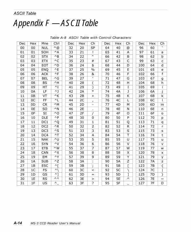
ASCII Table
Appendix F — ASCII TableTable A-8 ASCII Table with Control Characters
Dec Hex Mne Ctrl Dec Hex Ch Dec Hex Ch Dec Hex Ch00 00 NUL ^@ 32 20 SP 64 40 @ 96 60 `01 01 SOH ^A 33 21 ! 65 41 A 97 61 a02 02 STX ^B 34 22 “ 66 42 B 98 62 b03 03 ETX ^C 35 23 # 67 43 C 99 63 c04 04 EOT ^D 36 24 $ 68 44 D 100 64 d05 05 ENQ ^E 37 25 % 69 45 E 101 65 e06 06 ACK ^F 38 26 & 70 46 F 102 66 f07 07 BEL ^G 39 27 ' 71 47 G 103 67 g08 08 BS ^H 40 28 ( 72 48 H 104 68 h09 09 HT ^I 41 29 ) 73 49 I 105 69 i10 0A LF ^J 42 2A * 74 4A J 106 6A j11 0B VT ^K 43 2B + 75 4B K 107 6B k12 0C FF ^L 44 2C , 76 4C L 108 6C l13 0D CR ^M 45 2D - 77 4D M 109 6D m14 0E SO ^N 46 2E . 78 4E N 110 6E n15 0F SI ^O 47 2F / 79 4F O 111 6F o16 10 DLE ^P 48 30 0 80 50 P 112 70 p17 11 DC1 ^Q 49 31 1 81 51 Q 113 71 q18 12 DC2 ^R 50 32 2 82 52 R 114 72 r19 13 DC3 ^S 51 33 3 83 53 S 115 73 s20 14 DC4 ^T 52 34 4 84 54 T 116 74 t21 15 NAK ^U 53 35 5 85 55 U 117 75 u22 16 SYN ^V 54 36 6 86 56 V 118 76 v23 17 ETB ^W 55 37 7 87 57 W 119 77 w24 18 CAN ^X 56 38 8 88 58 X 120 78 x25 19 EM ^Y 57 39 9 89 59 Y 121 79 y26 1A SUB ^Z 58 3A : 90 5A Z 122 7A z27 1B ESC ^[ 59 3B ; 91 5B [ 123 7B {28 1C FS ^\ 60 3C < 92 5C \ 124 7C |29 1D GS ^] 61 3D = 93 5D ] 125 7D }30 1E RS ^^ 62 3E > 94 5E ^ 126 7E ~31 1F US ^_ 63 3F ? 95 5F _ 127 7F D
A-14 MS-3 CCD Reader User’s Manual

Appendices
Appendix G — Defaulting/Saving/Resetting Understanding and controlling your reader’s active, saved, and default settings is criti-cal to the operation of your reader.
Power-on ParametersPower-on parameters (saved by the <Z> command) are saved to NOVRAM and recalled and loaded into current parameters when power is cycled or the <Arp> command is issued.
Default/Reset Definitions
Defaults are original or saved customer settings that can be recalled, either by soft-ware reset <Zrd> or hardware reset (“Hardware Default” on page A-16).Defaulting the reader by <Zrd> resets the configuration parameters to Microscan default values. Defaulting might be necessary if you have make temporary changes, communications between the reader and another device are lost or interrupted, or you are using incompatible equipment (for example, a terminal that is set at 38.4 K baud communicating with a reader that is set at 115.2 K baud).1
Resets (“A” commands) affect only the current settings (active memory) and are not saved for power on or recall.Active Memory is where the reader’s active settings are stored during use. These are not available on power-on unless saved by a “Z” command.
Table A-9 Software Reset/Save/Recall Commands
<A> Reset (does not save for power-on)<Z> Save current settings for power-on
<Zrd> Recall Microscan default parameters and save for power-on
1. There are no menu options or host commands for resetting the configuration program.
MS-3 CCD Reader User’s Manual A-15
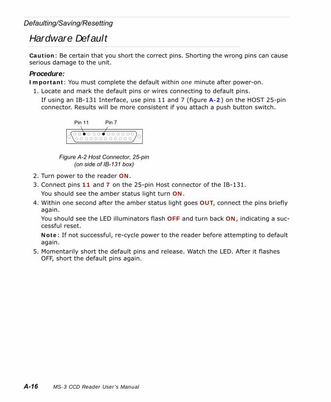
Defaulting/Saving/Resetting
Hardware Default
Caution: Be certain that you short the correct pins. Shorting the wrong pins can cause serious damage to the unit.
Procedure:Important: You must complete the default within one minute after power-on.1. Locate and mark the default pins or wires connecting to default pins.
If using an IB-131 Interface, use pins 11 and 7 (figure A-2) on the HOST 25-pin connector. Results will be more consistent if you attach a push button switch.
2. Turn power to the reader ON.3. Connect pins 11 and 7 on the 25-pin Host connector of the IB-131.
You should see the amber status light turn ON.
4. Within one second after the amber status light goes OUT, connect the pins briefly again. You should see the LED illuminators flash OFF and turn back ON, indicating a suc-cessful reset.
Note: If not successful, re-cycle power to the reader before attempting to default again.
5. Momentarily short the default pins and release. Watch the LED. After it flashes OFF, short the default pins again.
Figure A-2 Host Connector, 25-pin (on side of IB-131 box)
Pin 7Pin 11
A-16 MS-3 CCD Reader User’s Manual
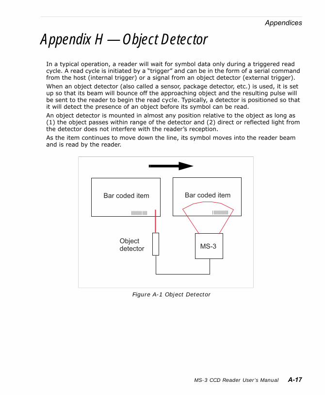
Appendices
Appendix H — Object DetectorIn a typical operation, a reader will wait for symbol data only during a triggered read cycle. A read cycle is initiated by a “trigger” and can be in the form of a serial command from the host (internal trigger) or a signal from an object detector (external trigger).When an object detector (also called a sensor, package detector, etc.) is used, it is set up so that its beam will bounce off the approaching object and the resulting pulse will be sent to the reader to begin the read cycle. Typically, a detector is positioned so that it will detect the presence of an object before its symbol can be read. An object detector is mounted in almost any position relative to the object as long as (1) the object passes within range of the detector and (2) direct or reflected light from the detector does not interfere with the reader’s reception.As the item continues to move down the line, its symbol moves into the reader beam and is read by the reader.
Bar coded item
Objectdetector MS-3
Bar coded item
Figure A-1 Object Detector
MS-3 CCD Reader User’s Manual A-17
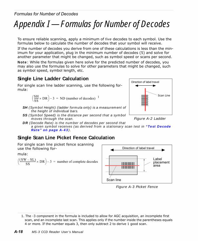
Formulas for Number of Decodes
Appendix I — Formulas for Number of DecodesTo ensure reliable scanning, apply a minimum of five decodes to each symbol. Use the formulas below to calculate the number of decodes that your symbol will receive.If the number of decodes you derive from one of these calculations is less than the min-imum for your application, plug in the minimum number of decodes (5) and solve for another parameter that might be changed, such as symbol speed or scans per second.Note: While the formulas given here solve for the predicted number of decodes, you may also use the formulas to solve for other parameters that might be changed, such as symbol speed, symbol length, etc.
Single Line Ladder CalculationFor single scan line ladder scanning, use the following for-mula:
1
SH (Symbol Height) (ladder formula only) is a measurement of the height of individual bars.
SS (Symbol Speed) is the distance per second that a symbol moves through the scan.
DR (Decode Rate) is the number of decodes per second that a given symbol receives (as derived from a stationary scan test in “Test Decode Rate” on page A-43).
Single Scan Line Picket Fence Calculation For single scan line picket fence scanning use the following for-
mula:
1. The -3 component in the formula is included to allow for AGC acquisition, an incomplete first scan, and an incomplete last scan. This applies only if the number inside the parentheses equals 4 or more. If the number equals 3, then only subtract 2 to derive 1 good scan.
Direction of label travel
Scan Line
Figure A-2 Ladder
SHSS-------- DR×
3– ND (number of decodes)=
Scan line
Labelplacementarea
Direction of label travel
Figure A-3 Picket Fence
SW SL–( )SS
--------------------------- DR× 3– number of complete decodes=
A-18 MS-3 CCD Reader User’s Manual

Appendices
Angled Picket Fence Calculation The number of complete scans for angled picket fence is calculated the same as that for picket fence, with the exception that the scan width is shortened in proportion to scan tilt.
Improving the Number of Decodes
After changing any of the parameters described in this section, recalculate the number of decodes.
Range Adjusting the symbol’s range, if possible, is one of the quickest and most effective ways to improve decode rates. However, in some applications you may need to select a less than optimum range, or one that is beyond the fringes of the ranges.
Scan WidthIncreasing scan width will increase the number of scans in a picket fence oriented appli-cation. Scan width is linked with scan range and changing one will usually require a change in the other.
Symbol SpeedApplies to both picket fence and ladder oriented symbols. If your application allows it, slowing symbol speed (the time in seconds that a symbol is fully within the scan width of the reader) is an effective way to increase the number of decodes.
Symbol Dimensions, Symbol Density, and Symbol RatioNot usually an option in most applications, but changes to symbol parameters can affect number of decodes calculations and possibly decode rates.If your application allows it, shortening the length of a picket fence symbol means the symbol will be in the scan range longer and hence receive a greater number of scans. Increasing the height of a ladder symbol means it will receive more scans. Changing symbol density and/or symbol ratio is another way ranges, decode rates, etc. can be altered.
Direction of symbol travel
Scan Line
Figure A-4 Angled Picket Fence
MS-3 CCD Reader User’s Manual A-19

Operational Tips
Appendix J — Operational TipsDo:• Check inputs (symbol speed, length, height, etc.) to ensure the desired number of
decodes per symbol.• Connect reader to host before connecting power to the reader; disconnect power
before disconnecting the host from the reader.• For optimum decodes, mount reader so that your symbols pass through the center
of the depth-of-field (minimum/maximum range). You find the center by moving your symbol in and out during a read rate test.
• Avoid excessive tilt, pitch, and skew of the symbol.• Check the symbol for readability by doing a decode rate test. If there is any ques-
tion about the symbol's readability, contact your Microscan representative at [email protected].
• After changing any parameter that might affect decode rate, repeat decode rate test.
• Clean the reader window with a clean, dry Q-tip or cotton cloth on a regular basis.
Do Not:• Aim the reader into direct light or sunlight.• Aim the reader into an external object detector or other light-emitting device.• Obstruct the reader window with mounting hardware or other objects.• Connect chassis of reader and host to different ground potentials.• Operate the reader in excessive temperature environments.
A-20 MS-3 CCD Reader User’s Manual
Appendices
Appendix K — Glossary of TermsAnalog Gain Adjustment (AGC). Adjustment to signal strength that seeks to maintain a constant level regardless of the range of the symbol.Application Record. A variation of UCC/EAN-128 which adds an application identifier to symbol data, including user-definable separators, brackets, and padding.Autodiscriminate. The ability to decode several different symbologies without chang-ing configuration.Auxiliary Port. Provides RS-232 connections to an auxiliary terminal or device for remote viewing, for the transfer of data to and from the host, and under certain condi-tions as a configuration port.Bar Code. The medium or label on which a symbol is printed or etched.Bar Code Data. The information that is transmitted from a decoded bar code symbol.Baud Rate. The number of discrete signal events per second. Bits per second.Calibration. A routine that cycles through various optical settings and selects the com-bination that produce the best read rate.Capture. The act of grabbing or recording a frame by a sensor. A frame or succession of frames that are captured.Check Digit. A Modulus 43 or Modulus 10 digit that is added to the symbol message for additional data integrity.Configuration. A setup or process of changing a reader’s settings to conform to a spe-cific application. A physical arrangement of components.Concentrator. Intermediary device that relays data from readers to a host and com-mands from the host to the reader or other devices.Connector. Physical device (plug or socket) on a device or cable to provide in/out con-nectivity for various circuits and pins.Counter. Memory space provided to keep track of reader events.Daisy Chain. Linkage of master and slave readers to allow data to be relayed up to the host via auxiliary port connections. Decode. A good read. The successful scanning and decoding of the information encoded in symbol.Default. (verb) Restore Microscan or customer default settings, initialize serial com-mands and reset all counters.Defaults. (noun) The settings that are restored whenever a default takes place.Delimited. A command or field that is bracketed by pre-defined characters.Decode Rate (DR) The number of decodes per second that a given reader is capable of receiving.Depth of Field. The distance between the minimum and maximum range in which symbols have been read.Discrete I/O. Inputs and outputs characterized by discrete signal transitions from one voltage level to another so that digital switching can occur.
MS-3 CCD Reader User’s Manual A-21

Glossary of Terms
Dynamic Setup. Testing and configuration done with symbols in motion.EPROM. Erasable, programmable, read only memory.Embedded Memory. Onboard memory device such as EPROM or flash.End of Read Cycle. The time or condition at which the reader stops expecting symbol information to decode.Edge. Allows a read cycle to be initiated by a trigger signal from an object detector when it detects the appearance of an object (rising edge). The read cycle ends with a good read, a timeout, or a new trigger.ESP. Easy Setup Program. A portable proprietary Windows/NT based program devel-oped by Microscan Systems, Inc.Falling Edge. A change of state (to inactive) associated with a level trigger in which the reader stops searching for symbols. (See Rising Edge.)Fixed Code Length. Increases data integrity by ensuring that only one symbol length will be accepted.Flash Memory. Memory that can be changed by downloading new code and recalled on power-on.Focal Length. The distance measured from the reader to the center of the depth of field, or focal point.
Focus. The point at which the tip of the scan beam is at its narrowest.Full Duplex. Auxiliary port data is sent directly to the host but not displayed on the auxiliary port screen.Gain. Optimal signal strength.Good Match. The event occurring when a scanned symbol matches the master symbol information that is stored in the memory of the device.Good Read. A decode. The successful scanning and decoding of the information encoded in a symbol.Half Duplex. Auxiliary port data is sent directly to the host and displayed on the auxil-iary port screen.Host. A computer, PLC, or other device that is used to execute commands and process data and discrete signals.Host Port. The pins or connections on a reader or other device that physically connect with a host and—using the RS-232, RS-422, or RS-485 standards—pass data and serial commands from one device to another.Initialize. Implement serial configuration commands into the reader’s active memory.Input. A channel or communications line. Decoded data or a discrete signal that is received by a device. See Output.Intercharacter Delay. The time interval in milliseconds between individual characters transmitted from the reader to the host.Intercharacter Gap. The extra space between the last element of one character and the first element of the adjacent character of a specific bar code symbol.Ladder Symbol Orientation. A bar code symbol in which the bars are parallel to the symbol’s direction of travel.Large Intercharacter Gap. Allows the reader to read symbols with gaps between
A-22 MS-3 CCD Reader User’s Manual
Appendices
symbol characters that exceed three times (3x) the narrow element width.LED. Light emitting diode.Level. The condition in which a read cycle initiated by a trigger signal from an object detector remains active and ends when the object moves out of the detector’s range.Longitudinal Redundancy Check (LRC). An error-checking routine that verifies the accuracy of transmissions.Master Symbol. A symbol or symbol data that is stored in a reader or reader’s mem-ory and is compared with subsequently read symbols.Master Reader. First reader in a daisy chain mode and linked directly to the host and in tandem to slave readers.Matchcode. The ability to compare symbol data being scanned against a master sym-bol that is stored in the memory of the reader.Embedded Menu. Configuration options embedded in the reader’s erasable memory.ESP Menu. Easy Setup Program. Configuration program that runs in Windows-based operating systems 95 and above.Mil. One thousandths of an inch or 0.0254 mm. In bar-coding, a measurement stan-dard that identifies a symbol by the width of its narrowest element. Mismatch. An event that occurs when the scanned symbol does not match the master symbol that is stored in the memory of the reader.Multisymbol. A reader mode which allows a reader to read more than one symbol in a single read cycle.Multidrop. A communications protocol for networking two or more readers or other devices with a concentrator (or controller) and characterized by the use of individual device addresses and the RS-485 standard.Narrow-bar-width. The width of the narrowest bar of a specific bar code symbol, expressed in thousands of an inch (or mils) as defined by standard code types.Narrow Margins. Allows the reader to read symbols with quiet zones less than 8 times the width of the narrow bar element.Non-delimited. A command that is not bracketed by pre-defined characters.Noread. A non-read. A condition that occurs when the reader is set up to decode sym-bols but no symbol is scanned during the read cycle.Normally Closed. A discrete output state that is only active when open.Normally Open. A discrete output state that is only active when closed.NOVRAM. Non-volatile random access memory. Data that is “saved for power-on” is saved to NOVRAM.Null. Also spelled “Nul.” A non-printed ASCII character that acts as a space-holder.Number of Decodes. The number of times a symbol is scanned by the reader during one pass through the laser beam.Object Detector. A photo electric device used to sense the presence or absence of an object (also referred to as a package detector).Output. A channel or communications line. Data or discrete signals that are transmit-ted or displayed by a device.Output Format. The modification of data output according to a user-defined index of
MS-3 CCD Reader User’s Manual A-23

Glossary of Terms
Extraction and Insertion commands.Parity. An error detection routine in which one data bit in each character is set to 1 or 0 (zero) so that the total number of 1 bits in the data field is even or odd.Picket Fence Symbol Orientation. A bar code symbol in which the bars are perpen-dicular to the symbol’s direction of travel.Pitch. Symbol (or reader) rotation around the center of a line parallel to the scan beam.Point-to-Point. A protocol consisting of a single communications event, typically used to connect a bar code reader to a terminal or host computer.Port. Logical circuit for data entry and exit. (One or more ports may be included within a single connector.)Protocol. The rules for communication between devices, providing a means to control the orderly flow of information between linked devices.Quiet Zones. Specified “clear” (non printed) areas immediately before and after the bar code symbol. The area is usually white (for black and white symbol) and at least 10 times the width of the narrowest bar, as measured in thousands of an inch. The zones can be other than white as long as their densities remain consistent and they have the required contrast relative to the bars.RAM. (Random Access Memory) Memory that is lost after power is recycled to the unit.Read Cycle. A programmed period of time or condition during which the reader will accept symbol input.Reader. (1) A reader, a bar code device that can read and decode symbols. (2) A device that reads and decodes 2D matrix codes.Read Range. The distances in which a symbol can be reliably read, as measured from the front of the reader. See “Depth of Field.”Reed-Solomon Error Correction Code. A linear, error correcting block code, suited to the correction of character errors which could be, in bar or matrix codes, the oblitera-tion or removal of part of the symbol.Read Range. The distances in which a symbol can be reliably read, as measured from the front of the reader. See “Depth of Field.”Relay. An electrical switch that allows a low power to control a higher one.Reset. Sets all counters to zero.Rising Edge. A change of state (to active) that initiates (and in some cases ends) a read cycle with a new trigger, an edge trigger, or the leading edge of a level trigger. (See Falling Edge.)ROM. (Read Only Memory) Memory that cannot be changed.Reader. A scanning device that is comprised of a scan head and a decoder integrated in one package.Scan Speed. The number of scans per second that a reader projects from the spinning mirror.Scan Width (SW) is the width across the scan beam at a given distance from the reader in which a symbol can be read. Send. Transmit data from one device to another.Secondary Reader. A reader linked to the master or preceding reader in a daisy chain
A-24 MS-3 CCD Reader User’s Manual
Appendices
which relays symbol data to the host. See “Daisy Chain.”Separator. A character that separates data fields. Serial Commands. Online data strings such as <D> or <P> sent from a host or auxil-iary terminal to a reader or other device.Serial Configuration (Host Configuration). Serial commands that change configura-tion; distinguished from operational command by the fact that they can modify non-vol-atile memory for power-on configuration.Skew. Symbol (or reader) rotation around the center of the skew axis which is perpen-dicular to the plane of the scan beam.Specular Reflection. The direct, mirror-like reflection of light back to the source caus-ing saturation and bad reads.Supplemental. A character or data string that is appended to the main bar code sym-bol.Symbol. A one or two dimensional decodable pattern that can be recognized and decoded by a bar code reader or 2D reader.Symbology. A code type, such as Code 39 or Code 128, with special rules to define the widths and positions of bars and spaces to represent specific numeric or alphanumeric information.Symbol Density. Symbol size as measured by the narrow bar width.Symbol Height. (SH) Regardless of orientation, the measurement taken along the length of a symbol’s individual bars.Symbol Length. (SL) Regardless of orientation, the measurement taken across the symbol's bars from one end to the other, including the quiet zone.Symbol Speed. (SS) the distance per second that a symbol moves in a dynamic appli-cation.Symbol Transitions. The transition of bars and spaces on a symbol, used to detect the presence of a symbol on an object.Tilt. Symbol (or reader) rotation around the centerline of the scan beam.Timeout. The termination of a read cycle or other routine by time.Timeout Duration. The actual time that elapses during a read cycle or other timed routine.Tracking. Adjustment of the precision of analog-to-digital conversion.Transmit. Send or convey signals or information from one device to another.Transparent. Data that passed between the auxiliary port and the host with keyed data echoed to the auxiliary portTrigger. A signal, transition, or character string that initiates a read cycle.Watchdog Timer. A security device that detects system crashes and attempts to reset the reader.Watchdog Reset. A reset that is forced whenever the software locks up.Wild Card. User-defined character entered into a master symbol to permit matches with variable characters.
MS-3 CCD Reader User’s Manual A-25

Glossary of Terms
A-26 MS-3 CCD Reader User’s Manual

Index
AAbout This Manual i-viiiAmbient light A-2App Mode button 1-7Application code 5-3Approvals i-ixASCII Table, including control characters
A-14Automatic Gain Control 3-14
BBaud Rate
host port 2-3BSMI i-ix
CCE Compliance i-ixCE Mark A-2Character 3-9Check Digit
Code 39 4-4I-2/5 4-7Industrial 2/5 4-16
Check Digit Output StatusMSI Code 4-19Plessy Code 4-20
Check Digit StatusIndustrial 2/5 4-16
Code 128 4-6Code 39 4-4Code 93 4-15Communications
by ESP 2-2by Serial Command 2-2
Configuration Command Status 5-5Connect the System 1-2Connectivity A-5Connector A-2Continuous Read 3-6Continuous Read 1 Output 3-6Control Characters A-13cUL i-ix
DData Bits
host port 2-3Decode Rate A-18Decodes Before Output 3-12Defaulting 5-4, A-15Definitions A-15delimited 3-9Device Control 5-4Disclaimer i-iiiDownload code 5-3
EEAN-13 Status
UPC/EAN 4-12EAN-8 as EAN-13
UPC/EAN 4-14EAN-8 Status
UPC/EAN 4-12Easy Setup Program 1-3Electrical Specifications A-4Electrical, IB-131 A-9Emulation 3-6Environmental, Specifications A-2ESP 1-3
MS-3 CCD Reader User’s Manual I-1
External Trigger Edge 3-8, 3-9External Trigger Level 3-7
FFCC i-ixFile Transfer 5-3Filter List 3-15Filter Mode 3-15Filter Selection 3-16Find Function, Terminal 6-3Firmware 5-3Firmware Verification 5-3FIS Options A-2Format
Industrial 2/5 4-17Formulas for Number of Decodes A-18Full ASCII Set (Code 39) 4-5
GGain A-19General Specifications A-2Glossary of Terms A-21
HHardware Required 1-2Highlighting i-viiiHost Communications i-viiiHost Connector A-4Host Connector (25-pin), IB-131 A-8Host Port Connections 2-3Host Port Protocol 2-4Humidity A-2
II 2/5 symbol 1-6IB-131 Interface Module A-8IC-332 A-5Immunity A-2Industrial 2 of 5 4-16Install ESP 1-3Interleaved 2 of 5 4-7
KK Commands A-12
LLabel Density A-19Label Dimensions A-19Label Ratio A-19Label Speed A-19Ladder Calculation, single line A-18Laser Scanning 5-4Lighting Intensity 3-15
MMacros 6-4Maximum Speed, shutter 3-14Mechanical A-2Minimum Speed, shutter 3-14Minimum Symbol Length 4-5
Code 93 4-15MSI Code 4-19Plessy Code 4-20
MSI Code 4-18
NNetwork Connector (25-pin), IB-131 A-8New Master Inputs A-7Non-delimited 3-10Noread Message, output 3-13Not Optoisolated A-7NULs, defining A-13Number of Symbols 3-4
OObject Detector A-17Object detector 1-2object detector A-5Operating life A-2Operational Tips A-20Optics A-2Optoisolator Inputs A-7Output Format
UPC/EAN 4-14
PParity
host port 2-3Picket Fence Calculation
Angled A-19
I-2 MS-3 CCD Reader User’s Manual
Single Scan Line A-18Pin Assignments A-4Pitch 1-6Plessey Code 4-20Point-to-Point
standard 2-4with RTS/CTS 2-5
Position Symbol 1-6Postamble Characters 2-7Power Connector (3-pin), IB-131 A-8Power Input A-7Power-on Parameters A-15Product Labels i-ix
RRange A-19Read Cycle
by ESP 3-2by Serial Command 3-2by serial command 3-2
Read Cycle Differences 3-2, 3-3Read Ranges A-3Reader Selection 1-4Reader Setup 3-14Reader Status Requests 5-5Recall factory default parameters and save for
power-on 5-4, A-15Reset 5-4, A-15RSS Limited 4-22
SSafety Certifications A-3Save current settings for power-on 5-4, A-15Saving 5-4, A-15Scan rate A-2Scan Width A-2, A-19Scanner Connector (15-pin), IB-131 A-8Scanning Performance A-2Serial Command Format A-12Serial Command Status Request A-13Serial Commands, concatenating A-13Serial Configuration Commands A-12Serial Configuration Summary
Read Cycle 3-2Serial Data 3-9
Serial Trigger Characterdelimited 3-9
Serial Utility Commands A-12Setup Mode 1-7Shutter Speed 3-14Special Characters in Embedded Menus A-13Special Characters in Serial Commands A-13Specular reflection 1-6Start Character, trigger (non-delimited) 3-10Stop Bits
host port 2-3Stop Character, trigger (non-delimited) 3-10Supplemental 2 Status
UPC/EAN 4-13Supplemental 5 Status
UPC/EAN 4-13Supplementals
UPC/EAN 4-13Symbol Length
Codabar 4-11I-2/5 4-8
Symbol Length #1Industrial 2/5 4-17
Symbol Length #2Industrial 2/5 4-18
Symbol Speed A-18Symbol Types A-2Symbologies
by ESP 4-2by serial command 4-3
Symbology ID 4-24
TTBID 3-5Terminal Window 6-2Terminal Window Functions 6-5Time Between Identical Decodes 3-5Trigger 3-6, A-7Trigger Connector (4-pin), IB-131 A-8Trigger Mode 3-6
UUL i-ixUPC/EAN 4-12UPC-A as EAN-13
UPC/EAN 4-14
MS-3 CCD Reader User’s Manual I-3

UPC-A StatusUPC/EAN 4-12
UPC-E as UPC-AUPC/EAN 4-14
UPC-E StatusUPC/EAN 4-12
Utilitiesby ESP 5-2by serial command 5-2
Utility Commands A-12
WWarranty Statement i-ivWindows 1-3
I-4 MS-3 CCD Reader User’s Manual