mrf24j40 radio utility driver program
TRANSCRIPT
© 2009 Microchip Technology Inc. DS01192B-page 1
INTRODUCTIONThe MRF24J40 Radio Utility Driver program providesdesign engineers a development and testing platformfor the MRF24J40 IEEE 802.15.4™ 2.4-GHz RF trans-ceiver. The program configures and runs tests of basictransceiver functionality such as transmission, recep-tion sleep and Turbo mode, using a command-line andmenu-driven user interface.
The MRF24J40 utility program can run on either thePICDEM™ Z or Explorer 16 development board, towhich the MRF24J40 RF transceiver is attached. Theboard is connected to a PC’s serial port and operatedfrom a hyper terminal command window. For moredetails on the setup, see the section “Getting Started”on page 1.
For more detailed testing, engineers can use additionaltools such a spectrum analyzer or the ZENA™ packetanalyzer, Microchip’s IEEE 802.15.4 sniffer program.For more details on the ZENA analyzer, see the“ZENA™ Wireless Network Analyzer User’s Guide”(DS51606).
The MRF24J40 utility program source code and hexfiles are in the application note's compressed file. Addi-tional reference material is listed in “References” onpage 22.
Supported FeaturesTable 1 gives the program’s basic features.
TABLE 1: MRF24J40 RADIO UTILITY DRIVER FEATURES
GETTING STARTEDTo set up the MRF24J40 RF transceiver:
1. Insert the MRF24J40 RF transceiver daughtercard into the development board.• If using the PICDEM™ Z development board,
see Figure 1 on page 2.• If using the Explorer 16 development board,
see Figure 2 on page 3.2. Plug in the power cord for the demonstration
board that will hold the MRF24J40 RF trans-ceiver.
3. Connect an RS-232-to-USB serial cablebetween the development board and thecomputer that will display the MRF24J40 utilityprogram user interface.
4. Program the demonstration kit with the appropri-ate hex file.
First-time users of MPLAB® ICD 2, see the“MPLAB® ICD 2 User’s Guide” (DS51331),Section 4.3.2, “Loading a Hex File.”
Author: Sushma Myneni andTeodor ManolescuMicrochip Technology Inc.
Feature Functionality
Sniffer/Packet Analysis Functions as a sniffer or packet analyzer, when transceiver is programmed in Receive mode.
IEEE 802.15.4™ Specification Compliance Transmits and receives packets compliant with the IEEE 802.15.4 specification.
All-Channel Energy Detection Performs energy-detect scans on all channels.Low-Power Testing Enables testing of the MRF24J40 RF transceiver in Sleep mode.End-to-End Testing Provides Packet Error Rate (PER) and Ping Pong testing between two transceivers.
AN1192MRF24J40 Radio Utility Driver Program

AN1192
DS01192B-page 2 © 2009 Microchip Technology Inc.
Using the PICDEM™ Z BoardThe MRF24J40 RF transceiver daughter card’s 12-pinconnector (P1) can be used to connect to thePICDEM Z motherboard’s J2 connector. That connec-tion supplies 3.3V power, four-wire SPI, Reset, wakeand interrupt connections to the MRF24J40 RF trans-ceiver.
For the schematics of the MRF24J40 RF transceiver’sdaughter card, see Appendix C of the “PICDEM™ ZDemonstration Kit User’s Guide” (DS51524).
FIGURE 1: MRF24J40 RF TRANSCEIVER ON PICDEM™ Z DEVELOPMENT BOARD

© 2009 Microchip Technology Inc. DS01192B-page 3
AN1192Using the Explorer 16 BoardThe MRF24J40 RF transceiver daughter card’s 30-pinconnector (P1), a PCB-edge connector, can be used toconnect to Explorer 16 development board’s PICtail™Plus connector (J5 or J6). That connection supplies3.3V power, four-wire SPI, Reset, wake and interruptconnections to the MRF24J40 RF transceiver.
For the schematics of the MRF24J40 RF transceiver’sdaughter card, see Appendix C of the “PICDEM™ ZDemonstration Kit User’s Guide” (DS51524). For theschematics of Explorer 16 development board, see the“Explorer 16 Development Board User’s Guide”(DS51589).
FIGURE 2: MRF24J40 RF TRANSCEIVER ON EXPLORER 16 DEVELOPMENT BOARD
Connecting to the Host PCThe PC displaying the MRF24J40 utility program’s userinterface connects to the development board throughthe PC’s serial port. PCs with the Windows® XP orWindows NT® operating system can use the HyperTer-minal program for communications to set up the userinterface.
Other serial port communications can be used andopen-source programs are available for downloadingand use.
The required configuration settings for the serial portcommunication program are shown in Table 2.
TABLE 2: SERIAL PORT SETTINGS Parameter Setting
Bits per second 19200Data bits 8Parity NoneStop bits 1Flow control None

AN1192
DS01192B-page 4 © 2009 Microchip Technology Inc.
USING THE DRIVER FIRMWARE
Firmware OverviewThe MRF24J40 utility program is operated through amenu displayed on the host computer, using a serialport communication application.
There are two major menus, shown in Figure 3.
FIGURE 3: PRIMARY MENUS
• The Main Menu primarily contains the test function commands
• The Configure Menu – accessed from the Main Menu – primarily configures the transceiver
Hot keys can be used to navigate through the menus.See Table 3.
TABLE 3: KEYBOARD HOT KEY COMMANDS
Figure 4 displays the Main Menu and the status andconfiguration values displayed by the hot keys<Ctrl> + <s>.
(a) Set the Operating Channel(b) Set TX Output Power(c) Enable/Disable Hardware CRC checking(d) Configure External PA & LNA(e) Set TX Delay Between Packets(f) Set the Number of Averaged RSSI Samples(g) Enable/Disable Turbo Mode(h) Set Ping Pong Test Package Size
(a) Configure MRF24J40(b) Set the Radio in Receiving Mode(c) Transmit Predefined Packet Continuously(d) Transmit Packet Defined by User(e) Test Low Power Mode(f) Energy Detection on All Channels(g) Test Simple Local Oscillator(h) Test Single Tone Modulation(i) Test Sequential Transmit Mode for All Channels(j) PER Test between Two Devices(k) Ping Pong Test(l) Dump Values of Transceiver’s Registers
(a)Main Menu
Configure Menu
Hot Key Functionality
<Ctrl> + <z>
Exit and return to Main Menu.
This hot key is used to stop/exit from any step.
<Ctrl> + <x>
Reset the transceiver and returnconfiguration settings to their defaultvalues.
This hot key can be used at any step.
<Ctrl> + <s>
Display the current system status andconfiguration values.
The displayed configuration values areshown in Figure 4.
This hot key can be used at any step inthe program.
<Ctrl> + <t>
Continuously transmit predefinedpacket.
This hot key can only be used from the Main Menu.
<Ctrl> + <r>
Set the radio in Receive mode (verbose).
This hot key can only be used from the Main Menu.

© 2009 Microchip Technology Inc. DS01192B-page 5
AN1192FIGURE 4: MAIN MENU AND STATUS LINE
AN1192
DS01192B-page 6 © 2009 Microchip Technology Inc.
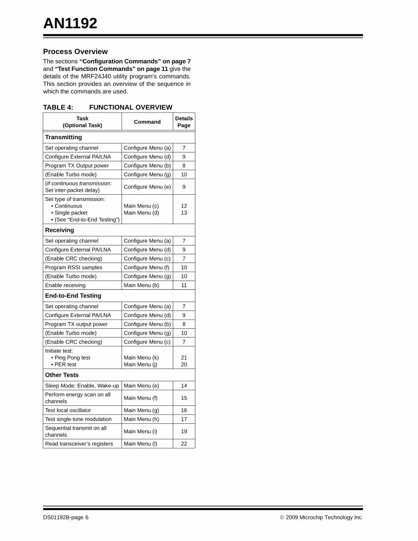
Process OverviewThe sections “Configuration Commands” on page 7and “Test Function Commands” on page 11 give thedetails of the MRF24J40 utility program’s commands.This section provides an overview of the sequence inwhich the commands are used.
TABLE 4: FUNCTIONAL OVERVIEWTask
(Optional Task) Command DetailsPage
TransmittingSet operating channel Configure Menu (a) 7Configure External PA/LNA Configure Menu (d) 9Program TX Output power Configure Menu (b) 8(Enable Turbo mode) Configure Menu (g) 10(If continuous transmission:Set inter-packet delay) Configure Menu (e) 9
Set type of transmission: • Continuous • Single packet • (See “End-to-End Testing”)
Main Menu (c)Main Menu (d)
1213
ReceivingSet operating channel Configure Menu (a) 7Configure External PA/LNA Configure Menu (d) 9(Enable CRC checking) Configure Menu (c) 7Program RSSI samples Configure Menu (f) 10(Enable Turbo mode) Configure Menu (g) 10Enable receiving Main Menu (b) 11
End-to-End TestingSet operating channel Configure Menu (a) 7Configure External PA/LNA Configure Menu (d) 9Program TX output power Configure Menu (b) 8(Enable Turbo mode) Configure Menu (g) 10(Enable CRC checking) Configure Menu (c) 7Initiate test: • Ping Pong test • PER test
Main Menu (k)Main Menu (j)
2120
Other TestsSleep Mode: Enable, Wake-up Main Menu (e) 14Perform energy scan on all channels Main Menu (f) 15
Test local oscillator Main Menu (g) 16Test single-tone modulation Main Menu (h) 17Sequential transmit on all channels Main Menu (i) 19
Read transceiver’s registers Main Menu (l) 22

© 2009 Microchip Technology Inc. DS01192B-page 7
AN1192
EXECUTING FIRMWARE COMMANDSThis section gives details about the commands issuedby the Main and Configure menus. Its subsectionsinclude:
• “Configuration Commands” – The Main Menu command for accessing the Configure Menu and the Configure Menu commands
• “Test Function Commands” – The test and functional commands on the Main Menu
Configuration CommandsThe MRF24J40 RF transceiver is ready to operate,using the MRF24J40 utility program’s default values.Those values are shown in Table 5.
TABLE 5: DEFAULT CONFIGURATION SETTINGS (1)
If desired, the values can be reconfigured through thesecondary, Configuration Menu displayed in Figure 5.
FIGURE 5: CONFIGURATION MENU
CONFIGURE MRF24J40This Main Menu command displays the ConfigurationMenu, shown in Figure 5.
SET OPERATING CHANNELThis Configuration Menu option, shown in Figure 6,enables the selection of one of the 16 operating chan-nels available in the 2.4-GHz range. The default oper-ating channel is 11.
When a channel is selected, the current system statusdisplays at the bottom of the screen. Check theChannel = value to confirm the setting.
FIGURE 6: OPERATING CHANNEL MENU
Attribute Setting
Channel 11TX Output Power 0 dBmHardware CRC Checking OnExternal PA and LNA OffTX Delay between Packets 1 unitNumber of averaged RSSI samples 1Turbo Mode OffPing Pong Test Package Size 100Note 1: Resetting the MRF24J40 RF transceiver
returns the settings to these default val-ues.
Note: For details on finding the channel with theleast noise, see “Energy Detection onAll Channels” on page 15.

AN1192
DS01192B-page 8 © 2009 Microchip Technology Inc.
SET TX OUTPUT POWERThis Configuration Menu option sets the transceiver’soutput power. The default transmitting output power is0 dBm.
This parameter is configured with a two-tier menu:
• The first menu designates the range from which the output power value will be chosen.
• The second menu specifies the output power value by indicating the value to be added to the beginning value of the previous menu’s range.See Table 6
TABLE 6: TX OUTPUT POWER MENUS – OUTPUT COMPUTATION
FIGURE 7: OUTPUT POWER RANGE AND SELECTION MENUS
The two-tier menus enable the values shown inTable 7.
TABLE 7: OUTPUT POWER VALUES
When the Tx output power value is programmed, the current system status displays on the screen. Check the TX Power = value to confirm the setting.
ENABLE/DISABLE HARDWARE CRC CHECKINGThis Configuration Menu option, as shown in Figure 8,enables or disables a Cyclic Redundancy Check (CRC)of incoming packets. If CRC checking is enabled,incoming packets with incorrect CRC will be discardedby the Medium Access Layer (MAC). If CRC checkingis disabled, even CRC-incorrect packets will be passedto the host layer.
FIGURE 8: CRC CHECKING MENU
By default, this feature is turned on.
When this parameter is set, the current system statusdisplays at the bottom of the screen. Check the statusline’s H/W CRC Checking value to confirm thechange.
Option fromRange Menu
Option fromFine-Scale Menu Output
Process x dBm to y dBm z dBm x + z dBm
Example (b)-10 to -20 dBm (b)0.5 dBm -10.5 dBM
Range Values
0 to -10 dBm
0 dBm 0.5 dBm 1.2 dBm 1.9 dBm2.8 dBm 3.7 dBm 4.9 dBm 6.3 dBm
-10 to -20 dBm
10 dBm 10.5 dBm 11.2 dBm 11.9 dBm12.8 dBm 13.7 dBm 14.9 dBm 16.3 dBm
-20 to -30 dBm
20 dBm 20.5 dBm 21.2 dBm 21.9 dBm22.8 dBm 23.7 dBm 24.9 dBm 26.3 dBm
-30 to -40 dBm
30 dBm 30.5 dBm 31.2 dBm 31.9 dBm32.8 dBm 33.7 dBm 34.9 dBm 36.3 dBm

© 2009 Microchip Technology Inc. DS01192B-page 9
AN1192CONFIGURE EXTERNAL PA AND LNAThis Configuration Menu option enables or disables anexternal Power Amplifier (PA) and Low Noise Amplifier(LNA). The configuration of those amplifiers is donethrough the MRF24J40 RF transceiver‘s generalpurpose digital I/O (GPIOx) pins. (For more informa-tion, see section 4.2 “External PA/LNA Control” ofthe MRF24J40 Data Sheet (DS39776).)
By default external PA and LNA option is disabled.
When the External PA and LAN are enabled, the cur-rent system status displays on the screen, as shown inFigure 9. Check the External PA/LNA value toconfirm the setting.
The external PA and LNA can subsequently be dis-abled by resetting the MRF24J40 RF transceiver –which returns the configuration to its default values. Todo this, press the hot keys <Ctrl> + <x>.
FIGURE 9: PA AND LNA MENU
SET TX DELAY BETWEEN PACKETSThis Configuration Menu option, shown in Figure 10,determines the size of the inter-packet delay betweencontinuously transmitted TX packets. (To have thetransmitting MRF24J40 RF transceiver send thesepackets, select Main Menu option (c) Transmit Pre-defined Packet Continuously.)
FIGURE 10: TX PACKETS DELAY MENU
The size of the delay can be set with the PC’s numberor letter keys – numbers configuring no delay to a 81-unit delay and letters setting a delay of 100 to 1,225units. (See Table 8.)
TABLE 8: TX PACKET DELAY MENU – DELAY CONFIGURATION
By default, the delay is one unit – the equivalent being:
• PICDEM Z board – 2 ms• Explorer 16 board – 4 ms
When the packet delay value is configured, the currentsystem status displays on the screen. Check thePacket Delay value to confirm the setting.
Note: Do not enable PA/LNA on theMRF24J40MA module. The module’sGPIO pins are grounded, doing that willdrive the pins to ground.
Key Type Value Example
Number n = n2 9 = 81
Letter
a = 10 = 102 b = 11 = 112
•••
z = 35 = 352
a = 100b = 121
•••
z = 1,225

AN1192
DS01192B-page 10 © 2009 Microchip Technology Inc.
SET NUMBER OF AVERAGED RSSI SAMPLESThe Received Signal Strength Indicator (RSSI) mea-sures the signal quality of a received packet. Using anRSSI measurement that is averaged over multiplereadings provides a more accurate value than a single-reading RSSI.
This Configuration Menu option, shown in Figure 11,sets the number of RSSI samples to be averaged. Theresulting measurement are displayed on the screen byusing the Main Menu option (a) Set the Radio inReceiving Mode. (See “Set the Radio in ReceivingMode” on page 11.)
FIGURE 11: RSSI SAMPLE MENU
By default, the sample size is one.
ENABLE/DISABLE TURBO MODEThe MRF24J40 RF transceiver has a Turbo mode thattransmits and receives data at 625 kbps – two and ahalf times the normal rate for proprietary protocols.
This Configuration Menu option, shown in Figure 12,enables or disables that mode.
FIGURE 12: TURBO MODE MENU
By default the Turbo mode is disabled.
When the mode is enabled or disabled, the current sys-tem status displays on the screen. Check the TurboMode value to confirm the setting.
SET PING PONG TEST PACKAGE SIZEThis Configuration Menu option, shown in Figure 12,sets the number of ping pong packets exchangedbetween the transmitting and receiving transceivers.(For more details about ping pong tests, see “PingPong Test” on page 21.)
FIGURE 13: PING PONG MENU
Type one to three digits and press <Enter>.
The default value of this parameter is 100.
Note: ZENA packet analyzer cannot capturepackets transmitted in Turbo mode.

© 2009 Microchip Technology Inc. DS01192B-page 11
AN1192Test Function CommandsTest activation and other functional commands areissued through the Main Menu, shown in Figure 14. Todisplay this menu from anywhere in the firmwareinterface, press <Ctrl> + <z>.
FIGURE 14: MAIN MENU
SET THE RADIO IN RECEIVING MODEThis Main Menu option displays a received packet’sstatistics on the screen. Two display modes are avail-able, as shown in Figure 15:
FIGURE 15: SET RADIO TO RECEIVE
• Verbose mode – Displays all of the packet data (See Figure 16.)
• Summary mode – Displays statistics accumulated and printed for every second (See Figure 17.)
FIGURE 16: RADIO IN RECEIVING MENU – VERBOSE MODE
FIGURE 17: RADIO IN RECEIVING MENU – SUMMARY MODE
When you select one of the options, the received datais displayed. To take the transceiver out of Receivingmode, press <Ctrl> + <z> – which also redisplays theMain Menu.
Before executing the command on the receiving trans-ceiver, ensure that you have executed one of the“transmit packet” commands on the transmittingtransceiver.

AN1192
DS01192B-page 12 © 2009 Microchip Technology Inc.
TRANSMIT PREDEFINED PACKET CONTINUOUSLYThis Main Menu option, shown in Figure 18, continu-ously transmits a predefined packet until <Ctrl> + <z>(Exit and Return to Main Menu) is pressed.
The predefined packet is:
FIGURE 18: TRANSMIT PREDEFINED PACKET MENU
Before executing this command:
1. Review the transmitting transceiver’s configura-tion values. (Most of these values can be dis-played by pressing <Ctrl> + <s>.)
The default configuration value are shown in“Configuration Commands” on page 7.
2. If some parameters need to be changed:• Display the Main Menu (by pressing <Ctrl> +
<z>) and select (a) Configure MRF24J40.The Configure Menu, shown in Figure 5,appears.
• Edit the desired parameter(s).• Return to the Main Menu (<Ctrl> + <z>).
The configuration for the delay between each packet(inter-packet delay) may need to be changed from itsdefault value (1 unit). If a second transceiver is usingthe MRF24J40 utility program as a receiver/sniffer, thetransmitting transceiver’s use of the default value maybe too short. The second transceiver may not be ableto display the continuously received packets. This par-ticularly can be the case when using high-speed com-munications such as the ZENA™ Packet Analyzer.
Figure 19 shows a second transceiver using the ZENAanalyzer to monitor a message sent with this com-mand.
If a second transceiver is using the MRF24J40 utilityprogram as a sniffer/analyzer, see “Set the Radio inReceiving Mode” on page 11.
FIGURE 19: TRANSMITTING MODE USING THE ZENA™ SOFTWARE DISPLAY
01 08 C4 FF FF FF FF 07 00 00 00 00 00

© 2009 Microchip Technology Inc. DS01192B-page 13
AN1192TRANSMIT PACKET DEFINED BY USERThis Main Menu option, shown in Figure 20, enablestransmission of a user-defined packet that conforms toIEEE 802.15.4™ specifications.
FIGURE 20: TRANSMIT DEFINED PACKET MENU
After the menu appears:
1. Type the hexadecimal values to be transmit-ted—capitalizing all letters.
2. Send the entered data by pressing <=> (the“equals” key).
The MRF24J40 utility program automaticallychecks if the packet conforms to the IEEE802.15.4 format.
• If the format is correct:– The message is sent.– The following message appears: Packet
Transmission – Success.– The Main Menu reappears.
• If the format is incorrect, an error message isdisplayed.
3. If an error message appears:• Double-check your message and retype it.• Repeat steps 1 and 2.
The user-defined packet is transmitted only once. Totransmit the same packet multiple times, re-execute the(d) Transmit Packet Defined by User option as manytimes as desired.
Figure 21 shows how the packet — sent in Figure 20 —appears on a second transceiver whose MRF24J40utility program has been set in Receive mode.
FIGURE 21: DEFINED PACKET, AS RECEIVED

AN1192
DS01192B-page 14 © 2009 Microchip Technology Inc.
TEST LOW-POWER MODEThis Main Menu option can:
• Put the MRF24J40 RF transceiver in Sleep mode• Wake the transceiver from Sleep mode• Reset the transceiver
The Sleep mode enables designers to measure theMRF24J40 RF transceiver’s Sleep current.
Figure 22 shows the option menu and the prompt thatappears when the transceiver is put into Sleep mode.
To bring the transceiver out of Sleep mode, use option(b) Wake up the MRF from Sleep Mode or reset thetransceiver. Resetting the transceiver returns all config-uration settings to their default values.
FIGURE 22: TEST LOW-POWER MODE MENU
© 2009 Microchip Technology Inc. DS01192B-page 15
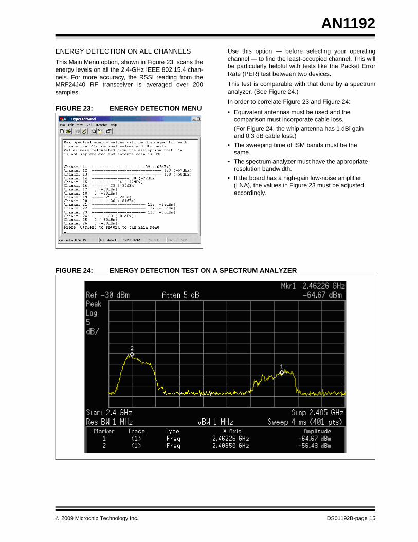
AN1192ENERGY DETECTION ON ALL CHANNELSThis Main Menu option, shown in Figure 23, scans theenergy levels on all the 2.4-GHz IEEE 802.15.4 chan-nels. For more accuracy, the RSSI reading from theMRF24J40 RF transceiver is averaged over 200samples.
FIGURE 23: ENERGY DETECTION MENU
Use this option — before selecting your operatingchannel — to find the least-occupied channel. This willbe particularly helpful with tests like the Packet ErrorRate (PER) test between two devices.
This test is comparable with that done by a spectrumanalyzer. (See Figure 24.)
In order to correlate Figure 23 and Figure 24:
• Equivalent antennas must be used and the comparison must incorporate cable loss.(For Figure 24, the whip antenna has 1 dBi gain and 0.3 dB cable loss.)
• The sweeping time of ISM bands must be the same.
• The spectrum analyzer must have the appropriate resolution bandwidth.
• If the board has a high-gain low-noise amplifier (LNA), the values in Figure 23 must be adjusted accordingly.
FIGURE 24: ENERGY DETECTION TEST ON A SPECTRUM ANALYZER

AN1192
DS01192B-page 16 © 2009 Microchip Technology Inc.
TEST SIMPLE LOCAL OSCILLATORThis Main Menu option, shown in Figure 25, can beused to check the frequency and output level of a localoscillator for a specific channel.
This command enables the local oscillator to startrunning without any modulation.
To end the test and return to the Main Menu, press<Ctrl> + <z>.
FIGURE 25: TEST LOCAL OSCILLATOR MENU
Before executing this test, select the required channel.
Figure 26 shows a comparable test by a spectrumanalyzer.
FIGURE 26: OSCILLATOR LEAKAGE TEST ON A SPECTRUM ANALYZER

© 2009 Microchip Technology Inc. DS01192B-page 17
AN1192TEST SINGLE TONE MODULATIONThis Main Menu option, shown in Figure 27, allowsusers to tune RF circuits and to see a Continuous Wave(CW) signal as the transceiver’s output. This single-tone modulation test can be done for a single channel(the first option) or for all the channels, one afteranother.
Figure 28 shows how the Single Channel test appearson a spectrum analyzer. Figure 29 shows how theSweeping Channels test appears on an analyzer.
To end the test and return to the Main Menu, press<Ctrl> + <z>.
FIGURE 27: SINGLE-TONE TEST MODULATION MENU
This Sweeping Channels option of this function alsocan be used to characterize the antenna gain on all thechannels. To do this, a good omni-directional antennashould be connected to the spectrum analyzer.
FIGURE 28: SINGLE-CHANNEL TONE TEST ON A SPECTRUM ANALYZER
Note: The actual level is 1 dB higher than the level displayed in this figure. That difference is dueto the loss in the coaxial cable used to measure the signal. This rule should be applied to allspectrum analyzer measurement presented in the application note.

AN1192
DS01192B-page 18 © 2009 Microchip Technology Inc.
FIGURE 29: SWEEPING-CHANNELS TONE TEST ON A SPECTRUM ANALYZER
© 2009 Microchip Technology Inc. DS01192B-page 19
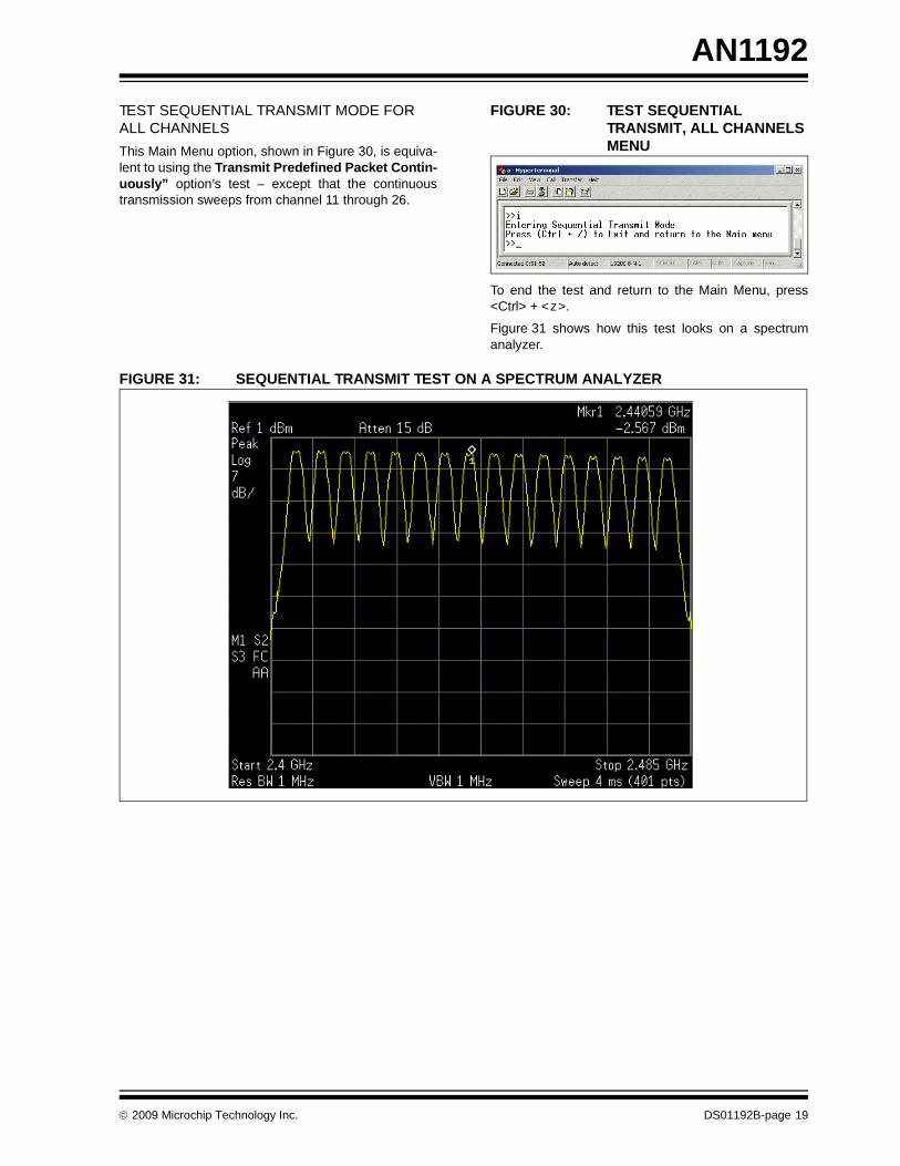
AN1192TEST SEQUENTIAL TRANSMIT MODE FOR ALL CHANNELSThis Main Menu option, shown in Figure 30, is equiva-lent to using the Transmit Predefined Packet Contin-uously” option’s test – except that the continuoustransmission sweeps from channel 11 through 26.
FIGURE 30: TEST SEQUENTIAL TRANSMIT, ALL CHANNELS MENU
To end the test and return to the Main Menu, press<Ctrl> + <z>.
Figure 31 shows how this test looks on a spectrumanalyzer.
FIGURE 31: SEQUENTIAL TRANSMIT TEST ON A SPECTRUM ANALYZER
AN1192
DS01192B-page 20 © 2009 Microchip Technology Inc.
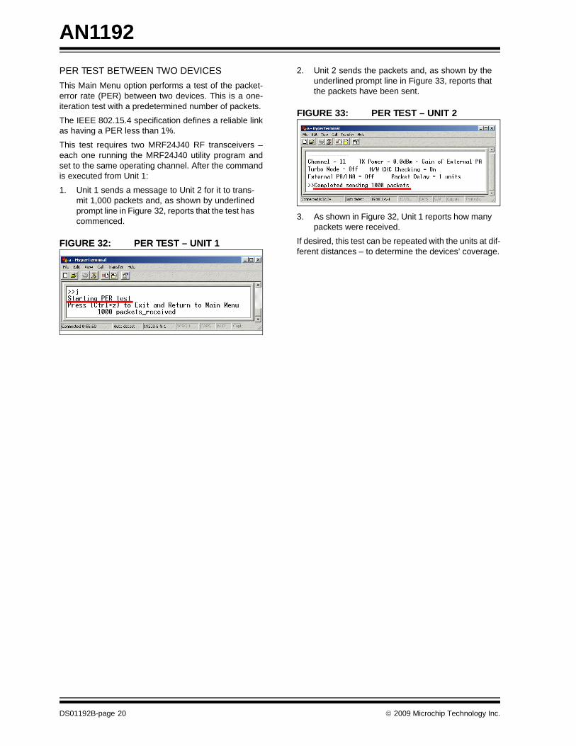
PER TEST BETWEEN TWO DEVICESThis Main Menu option performs a test of the packet-error rate (PER) between two devices. This is a one-iteration test with a predetermined number of packets.
The IEEE 802.15.4 specification defines a reliable linkas having a PER less than 1%.
This test requires two MRF24J40 RF transceivers –each one running the MRF24J40 utility program andset to the same operating channel. After the commandis executed from Unit 1:
1. Unit 1 sends a message to Unit 2 for it to trans-mit 1,000 packets and, as shown by underlinedprompt line in Figure 32, reports that the test hascommenced.
FIGURE 32: PER TEST – UNIT 1
2. Unit 2 sends the packets and, as shown by theunderlined prompt line in Figure 33, reports thatthe packets have been sent.
FIGURE 33: PER TEST – UNIT 2
3. As shown in Figure 32, Unit 1 reports how manypackets were received.
If desired, this test can be repeated with the units at dif-ferent distances – to determine the devices’ coverage.

© 2009 Microchip Technology Inc. DS01192B-page 21
AN1192PING PONG TESTThis Main Menu option tests for compliance to theEuropean standard for blocking and desensitization. Itmeasures the capability of a device to receive a signalwithout degradation due to unwanted signals at otherfrequencies.
The wanted signal’s degradation of its Packet ErrorRate (PER) must be less than 1% or the Bit Error Rate(BER) less than 0.1%.
The test requires two MRF24J40 RF transceivers –each one running the MRF24J40 utility program. Priorto initiating the test, both transceivers must be config-ured for the same operating channel (see “Set Operat-ing Channel” on page 7) and the same test-packagesize (see “Set Ping Pong Test Package Size” onpage 10).
A signal generator also will be needed. The generator’santenna should have at least 0 db gain.
To perform the test:
1. On Unit 1, select the Main Menu option (k) PingPong Test and select that menu’s option(a) Receive Ping Pong Test.
2. On Unit 2, activate the command and select theoption (b) Start Ping Pong Test.Unit 2 transmits the designated number of pack-ets to Unit 1 (see right-hand dialog box inFigure 34). Unit 1 (the left dialog box) reports thenumber of received packets and transmits thespecified number of packets to Unit 2.
The process continues until stopped.
3. While the packets are being exchanged, acti-vate a signal generator and modify its frequencysetting.
Use the signal generator to sweep a bandwidthlarge enough to create interference signals forthe two transceivers.
4. Watch the two dialog boxes and record the num-ber of lost packets.
5. To end the test and return to the Main Menu,press <Ctrl> + <z>.
If desired, this test can be repeated with the units at dif-ferent distances – to determine the devices’ coverage.
FIGURE 34: PING PONG TEST
Unit 1
Unit 2
AN1192
DS01192B-page 22 © 2009 Microchip Technology Inc.
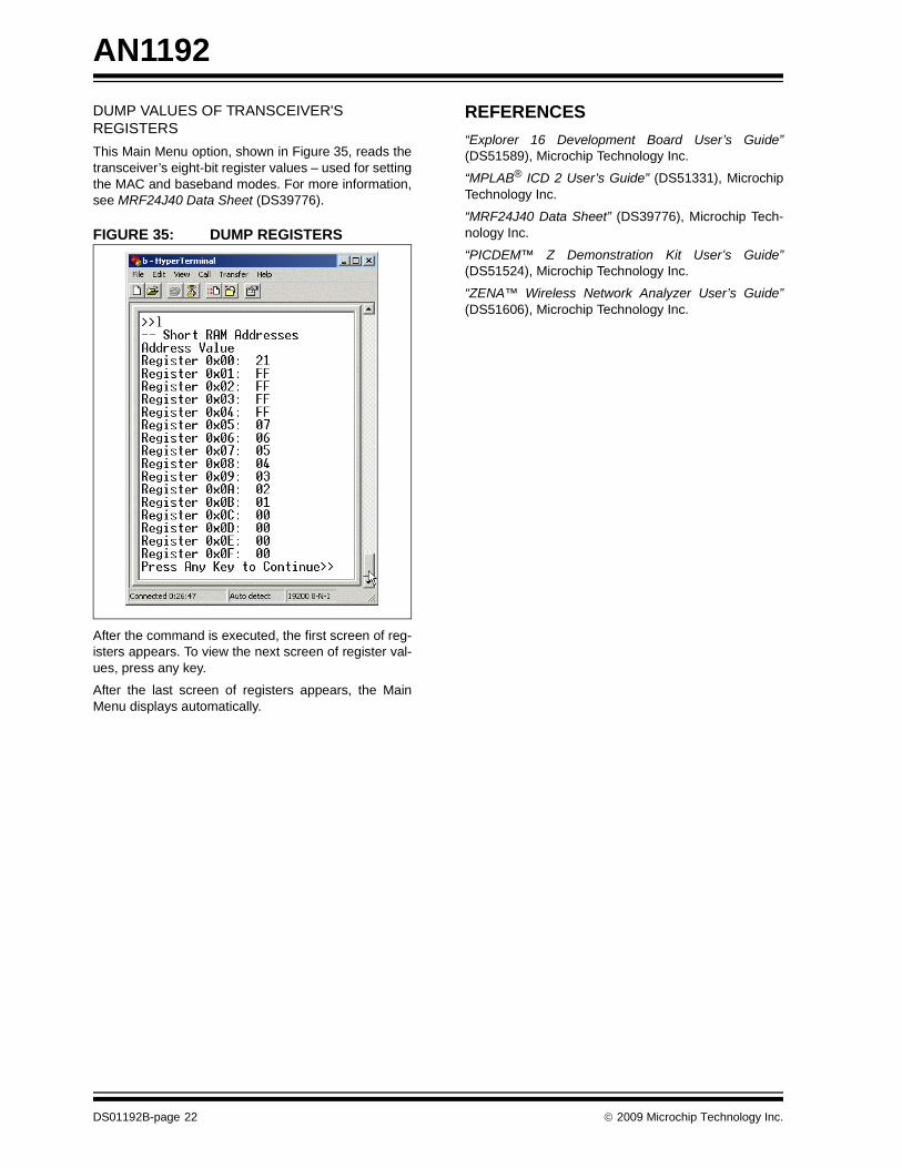
DUMP VALUES OF TRANSCEIVER'S REGISTERSThis Main Menu option, shown in Figure 35, reads thetransceiver’s eight-bit register values – used for settingthe MAC and baseband modes. For more information,see MRF24J40 Data Sheet (DS39776).
FIGURE 35: DUMP REGISTERS
After the command is executed, the first screen of reg-isters appears. To view the next screen of register val-ues, press any key.
After the last screen of registers appears, the MainMenu displays automatically.
REFERENCES“Explorer 16 Development Board User’s Guide”(DS51589), Microchip Technology Inc.
“MPLAB® ICD 2 User’s Guide” (DS51331), MicrochipTechnology Inc.
“MRF24J40 Data Sheet” (DS39776), Microchip Tech-nology Inc.
“PICDEM™ Z Demonstration Kit User’s Guide”(DS51524), Microchip Technology Inc.
“ZENA™ Wireless Network Analyzer User’s Guide”(DS51606), Microchip Technology Inc.
Note the following details of the code protection feature on Microchip devices:• Microchip products meet the specification contained in their particular Microchip Data Sheet.
• Microchip believes that its family of products is one of the most secure families of its kind on the market today, when used in the intended manner and under normal conditions.
• There are dishonest and possibly illegal methods used to breach the code protection feature. All of these methods, to our knowledge, require using the Microchip products in a manner outside the operating specifications contained in Microchip’s Data Sheets. Most likely, the person doing so is engaged in theft of intellectual property.
• Microchip is willing to work with the customer who is concerned about the integrity of their code.
• Neither Microchip nor any other semiconductor manufacturer can guarantee the security of their code. Code protection does not mean that we are guaranteeing the product as “unbreakable.”
Code protection is constantly evolving. We at Microchip are committed to continuously improving the code protection features of ourproducts. Attempts to break Microchip’s code protection feature may be a violation of the Digital Millennium Copyright Act. If such actsallow unauthorized access to your software or other copyrighted work, you may have a right to sue for relief under that Act.
Information contained in this publication regarding deviceapplications and the like is provided only for your convenienceand may be superseded by updates. It is your responsibility toensure that your application meets with your specifications.MICROCHIP MAKES NO REPRESENTATIONS ORWARRANTIES OF ANY KIND WHETHER EXPRESS ORIMPLIED, WRITTEN OR ORAL, STATUTORY OROTHERWISE, RELATED TO THE INFORMATION,INCLUDING BUT NOT LIMITED TO ITS CONDITION,QUALITY, PERFORMANCE, MERCHANTABILITY ORFITNESS FOR PURPOSE. Microchip disclaims all liabilityarising from this information and its use. Use of Microchipdevices in life support and/or safety applications is entirely atthe buyer’s risk, and the buyer agrees to defend, indemnify andhold harmless Microchip from any and all damages, claims,suits, or expenses resulting from such use. No licenses areconveyed, implicitly or otherwise, under any Microchipintellectual property rights.
© 2009 Microchip Technology Inc.
Trademarks
The Microchip name and logo, the Microchip logo, dsPIC, KEELOQ, KEELOQ logo, MPLAB, PIC, PICmicro, PICSTART, rfPIC and UNI/O are registered trademarks of Microchip Technology Incorporated in the U.S.A. and other countries.
FilterLab, Hampshire, HI-TECH C, Linear Active Thermistor, MXDEV, MXLAB, SEEVAL and The Embedded Control Solutions Company are registered trademarks of Microchip Technology Incorporated in the U.S.A.
Analog-for-the-Digital Age, Application Maestro, CodeGuard, dsPICDEM, dsPICDEM.net, dsPICworks, dsSPEAK, ECAN, ECONOMONITOR, FanSense, HI-TIDE, In-Circuit Serial Programming, ICSP, Mindi, MiWi, MPASM, MPLAB Certified logo, MPLIB, MPLINK, mTouch, Octopus, Omniscient Code Generation, PICC, PICC-18, PICDEM, PICDEM.net, PICkit, PICtail, PIC32 logo, REAL ICE, rfLAB, Select Mode, Total Endurance, TSHARC, UniWinDriver, WiperLock and ZENA are trademarks of Microchip Technology Incorporated in the U.S.A. and other countries.
SQTP is a service mark of Microchip Technology Incorporated in the U.S.A.
All other trademarks mentioned herein are property of their respective companies.
© 2009, Microchip Technology Incorporated, Printed in the U.S.A., All Rights Reserved.
Printed on recycled paper.
DS01192B-page 23
Microchip received ISO/TS-16949:2002 certification for its worldwide headquarters, design and wafer fabrication facilities in Chandler and Tempe, Arizona; Gresham, Oregon and design centers in California and India. The Company’s quality system processes and procedures are for its PIC® MCUs and dsPIC® DSCs, KEELOQ® code hopping devices, Serial EEPROMs, microperipherals, nonvolatile memory and analog products. In addition, Microchip’s quality system for the design and manufacture of development systems is ISO 9001:2000 certified.

DS01192B-page 24 © 2009 Microchip Technology Inc.
AMERICASCorporate Office2355 West Chandler Blvd.Chandler, AZ 85224-6199Tel: 480-792-7200 Fax: 480-792-7277Technical Support: http://support.microchip.comWeb Address: www.microchip.comAtlantaDuluth, GA Tel: 678-957-9614 Fax: 678-957-1455BostonWestborough, MA Tel: 774-760-0087 Fax: 774-760-0088ChicagoItasca, IL Tel: 630-285-0071 Fax: 630-285-0075ClevelandIndependence, OH Tel: 216-447-0464 Fax: 216-447-0643DallasAddison, TX Tel: 972-818-7423 Fax: 972-818-2924DetroitFarmington Hills, MI Tel: 248-538-2250Fax: 248-538-2260KokomoKokomo, IN Tel: 765-864-8360Fax: 765-864-8387Los AngelesMission Viejo, CA Tel: 949-462-9523 Fax: 949-462-9608Santa ClaraSanta Clara, CA Tel: 408-961-6444Fax: 408-961-6445TorontoMississauga, Ontario, CanadaTel: 905-673-0699 Fax: 905-673-6509
ASIA/PACIFICAsia Pacific OfficeSuites 3707-14, 37th FloorTower 6, The GatewayHarbour City, KowloonHong KongTel: 852-2401-1200Fax: 852-2401-3431Australia - SydneyTel: 61-2-9868-6733Fax: 61-2-9868-6755China - BeijingTel: 86-10-8528-2100 Fax: 86-10-8528-2104China - ChengduTel: 86-28-8665-5511Fax: 86-28-8665-7889China - Hong Kong SARTel: 852-2401-1200 Fax: 852-2401-3431China - NanjingTel: 86-25-8473-2460Fax: 86-25-8473-2470China - QingdaoTel: 86-532-8502-7355Fax: 86-532-8502-7205China - ShanghaiTel: 86-21-5407-5533 Fax: 86-21-5407-5066China - ShenyangTel: 86-24-2334-2829Fax: 86-24-2334-2393China - ShenzhenTel: 86-755-8203-2660 Fax: 86-755-8203-1760China - WuhanTel: 86-27-5980-5300Fax: 86-27-5980-5118China - XiamenTel: 86-592-2388138 Fax: 86-592-2388130China - XianTel: 86-29-8833-7252Fax: 86-29-8833-7256China - ZhuhaiTel: 86-756-3210040 Fax: 86-756-3210049
ASIA/PACIFICIndia - BangaloreTel: 91-80-3090-4444 Fax: 91-80-3090-4080India - New DelhiTel: 91-11-4160-8631Fax: 91-11-4160-8632India - PuneTel: 91-20-2566-1512Fax: 91-20-2566-1513Japan - YokohamaTel: 81-45-471- 6166 Fax: 81-45-471-6122Korea - DaeguTel: 82-53-744-4301Fax: 82-53-744-4302Korea - SeoulTel: 82-2-554-7200Fax: 82-2-558-5932 or 82-2-558-5934Malaysia - Kuala LumpurTel: 60-3-6201-9857Fax: 60-3-6201-9859Malaysia - PenangTel: 60-4-227-8870Fax: 60-4-227-4068Philippines - ManilaTel: 63-2-634-9065Fax: 63-2-634-9069SingaporeTel: 65-6334-8870Fax: 65-6334-8850Taiwan - Hsin ChuTel: 886-3-6578-300Fax: 886-3-6578-370Taiwan - KaohsiungTel: 886-7-536-4818Fax: 886-7-536-4803Taiwan - TaipeiTel: 886-2-2500-6610 Fax: 886-2-2508-0102Thailand - BangkokTel: 66-2-694-1351Fax: 66-2-694-1350
EUROPEAustria - WelsTel: 43-7242-2244-39Fax: 43-7242-2244-393Denmark - CopenhagenTel: 45-4450-2828 Fax: 45-4485-2829France - ParisTel: 33-1-69-53-63-20 Fax: 33-1-69-30-90-79Germany - MunichTel: 49-89-627-144-0 Fax: 49-89-627-144-44Italy - Milan Tel: 39-0331-742611 Fax: 39-0331-466781Netherlands - DrunenTel: 31-416-690399 Fax: 31-416-690340Spain - MadridTel: 34-91-708-08-90Fax: 34-91-708-08-91UK - WokinghamTel: 44-118-921-5869Fax: 44-118-921-5820
WORLDWIDE SALES AND SERVICE
03/26/09