mr c johnston ict teacher btec it unit 05 - lesson 03 network topologies
TRANSCRIPT

Mr C JohnstonICT Teacher
www.computechedu.co.uk
BTEC IT Unit 05 - Lesson 03
Network Topologies

Session Objectives
Be able to describe and sketch a range of network topologies,
Understand the advantages and limitations of each topology,
Know the features which make a topology useful, Know the features which make a topology vulnerable
to hardware failure.

Network Topologies Overview
The way a network laid out is called a topology, The topology used in a network determines how the computers and other devices are connected together, Common topologies which you need to be able to describe and sketch are:
Ring, Star, Bus, Tree, Mesh Drawings of a network can be either
a logical topology which shows a simplified representation of a network drawing - easy to understand but not to scale or has equipment / cable runs in the right place
a physical topology – the actual way a network is connected together - difficult to follow as will show the actual cable routes and positioning of all computers to scale – will often be drawn on a blank building plan so can see each room and floors.

The Ring Topology Made up of a number of computers / devices joined together in a continuous loop - may not be an actual ring shape but
no device has a terminator, Each device has a receiver which receives data from the device before it and a transmitter to send data to the next
device on the ring, Traffic is passed from one device to another in one direction till it reaches its destination, Device inspects each packet and if its not for it the packet gets forwarded on One computer could monitor the whole
network Becomes slower as grows
Data flows in one direction
Computers with receivers and transmitters

The Ring Topology Can be very fast as data travels one direction so no collisions, If computer switched off or faulty should be somehow for data still to be passed around the loop – if not whole network can be
fail as traffic only in one direction, Each device will re-broadcast the data packet so signal is stronger and can cover larger area than some topologies, No hubs / switches required to connect the devices together, If a cable stops working easy to find out where, Can add more computers but need to break the ring and be placed in-between two computers which can be a hassle, Quite a bit of cable use (not as much as star), Shape can make the topology inflexible.

The Star Topology Each device in the star network is connected to a central hub / switch with
its own connection, All communication is via the hub / switch so all data passes through it –
data travels in both directions, Hub broadcast all data to each device of the network but switches route
traffic to the correct port,
Client
ClientClient
ClientPrinter
Server
Hub / switch which all devices connect toDirection of data

The Star Topology Each device has own cable - The network is easy to setup, Easy to add more clients and devices and just plug them into the hub / switch, If one device / cable fails rest of the network still runs, Dependant on central hub – if this fails the whole network will fail, Easy to find faulty cable / device as will be the one which cant use the network, As each device has its own connection the network requires a lot of cabling –
metal prices are high at moment.

The Bus Topology All devices are connected in line to a common cable (backbone), Network traffic flows up and down the backbone, Each device connected to the backbone allows data to pass in both directions at
once and can send data (broadcast) from one computer to all, The cable is terminated at each end – terminators absorb the data packets, Each device must have the facility to send and receive data.
Terminator
Common Cable (Backbone)
Terminator Terminator
Direction of data

The Bus Topology Very easy to setup, Other than terminators no special connecting equipment (hubs / switches) needed and doesn’t need a lot of cable, New computers just added to the line, If a computer is turned off doesn’t effect the network that computer just cant be contacted, Network can be slow as all using the same cable – data can get corrupted, Not suitable for large or busy networks, Is a limit on the length of the backbone and number of devices which can be attached, If backbone breaks network fails.

The Tree Topology A tree topology combines characteristics of linear bus
and star topologies. It consists of groups of star networked devices
connected to a bus backbone Tree topologies allow for the expansion of an existing
network easily, Often an array of servers will sit on the backbone so
all segments will have access to them,
The Tree Topology Suitable for large networks as spilt up into manageable segments, Star networks may be one computer room with a fibre uplink to the backbone so
less cable required than making the whole network a star, Easy to expand / add more segments onto the network, If the backbone fails an entire segment may go down, Could be more difficult to configure and cable than other network topologies.

The Mesh Topology In a true mesh network every device has a connection to
every other device, Devices are connected together with many redundant
links, The network is very fast as each device can send data as
soon as it is ready to – only waiting is if the destination device is already receiving data from else where,
Each computer has its own switch which allows multiple computers to connect to it.
Every device has a connection to every other deviceEach machine needs is own switch
Switch
Direction of flow

The Mesh Topology Very fast as each device has a direct link to every other device – no collisions / corrupt data as all direct links Due to all the redundant links its fault tolerant – if one route is faulty there will be lots of others, Requires loads of cables and each device needs a switch so expensive, Every device needs to know which it is connected to, When a new device is added lots more cables are required – to add an extra device to the diagram on the last
slide another 6 cables are needed! Every existing device would need to be reconfigured so it knew how to get to the new device if the direct
cable failed.
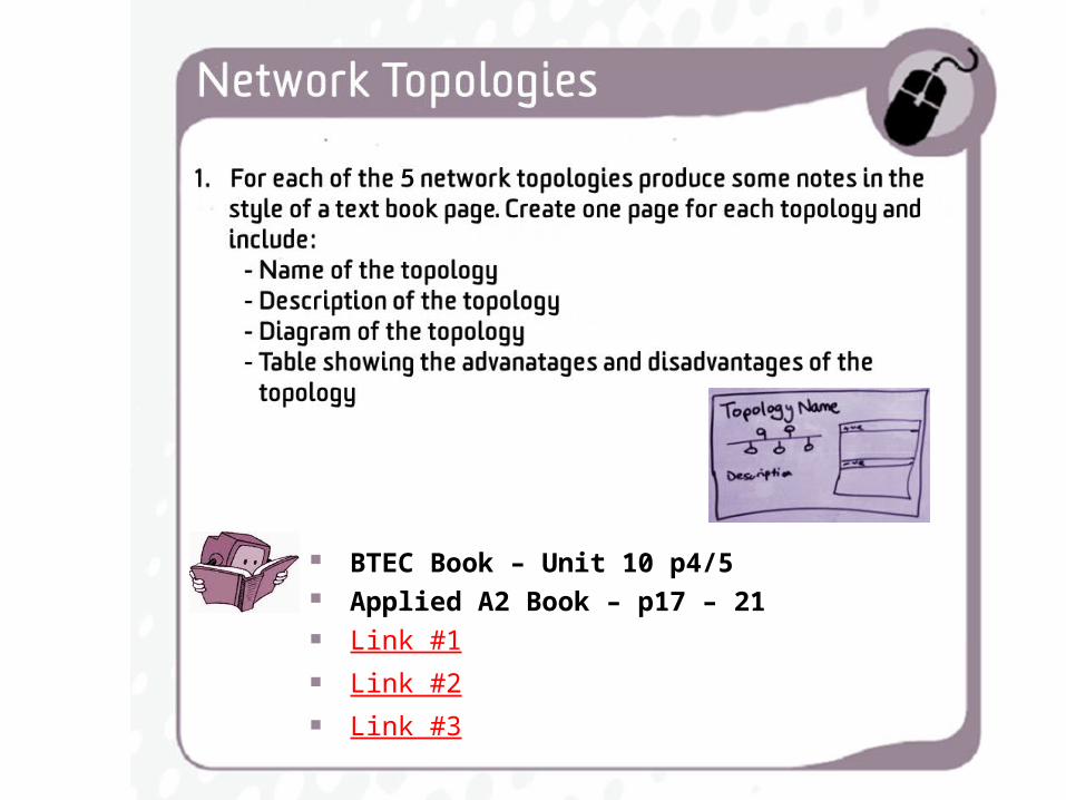
BTEC Book – Unit 10 p4/5 Applied A2 Book – p17 – 21 Link #1 Link #2 Link #3