mr angiography in the evaluation of lower extremity...
TRANSCRIPT

MR Angiography in the evaluation of
Lower Extremity Arterial Disease
March 2001
Ted Mau, Harvard Medical School Year IIIGillian Lieberman, MD
Ted MauGillian Lieberman, MD

2
Objectives
We will cover:• Indications for Magnetic Resonance
Angiography (MRA)• Basic principles of how MRA works• Advantages and limitations
Ted MauGillian Lieberman, MD

3
Our Patient
58 yo male with IDDM presents with non-healing right heel ulcer and bilateral claudication
Significant PMH: s/p right renal transplant 1994,
left renal transplant 2000
Ted MauGillian Lieberman, MD
4
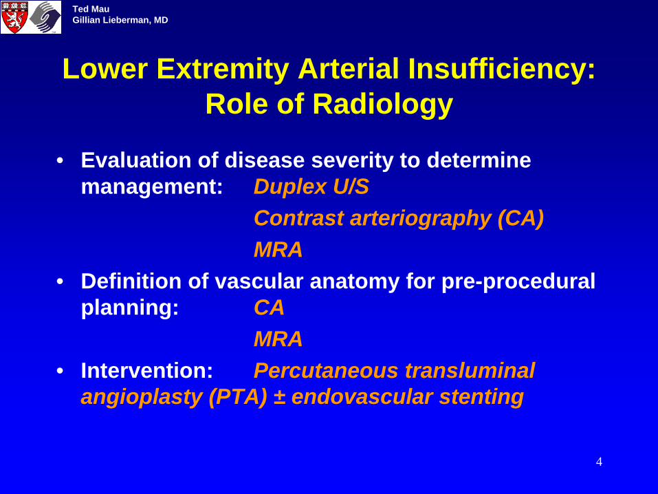
Lower Extremity Arterial Insufficiency: Role of Radiology
• Evaluation of disease severity to determine management: Duplex U/S
Contrast arteriography (CA)MRA
• Definition of vascular anatomy for pre-procedural planning: CA
MRA• Intervention: Percutaneous transluminal
angioplasty (PTA) ± endovascular stenting
Ted MauGillian Lieberman, MD

5
Contrast Arteriography: The Gold Standard
Requires:• Exposure to ionizing
radiation• Arterial puncture• Iodinated contrast -
potentially nephrotoxic (as high as 11% incidence of acute renal failure in patients with renal insufficiency* )
*O’Moore et al. Radiology 169(P):317, 1988.
thigh leg
foot
BIDMC
Superficial femoral artery
Profunda
Popliteal
Posterior tibial
Dorsalis pedis
Ted MauGillian Lieberman, MD

6
MR AngiographyAdvantages:•No ionizing radiation•Non-invasive•Contrast (gadolinium) is not nephrotoxic
Main Indication: Renal insufficiency
Ted MauGillian Lieberman, MD

7
QuestionsIf MRA has these advantages over contrast angiography:• Why don’t we use it for all patients?• Does it provide results comparable to contrast angiography?• What are its pros and cons?
A basic understanding of how MRA works will help us understand the advantages and limitations of MRA. Let’s begin by looking at what flowing blood looks like on MRI.
Ted MauGillian Lieberman, MD

8
MRA: How does it work?
Blood has variable intensity on MRI images. How do we use the same machine to selectively look at blood flow?
BIDMC
Ted MauGillian Lieberman, MD

9
Excitation and Relaxation: A Tuning Fork
Let’s review the basic concept of excitation and relaxation by looking at a tuning fork. After we strike the tuning fork (excitation), the amplitude of the vibration decreases with an exponential envelope (relaxation).
Ted MauGillian Lieberman, MD

10
Excitation and Relaxation: Nuclear Magnetization
The net magnetization of a group of protons can also undergo excitation and relaxation. At equilibrium, the magnetization vector lies in the direction of the magnetic field of the MRI spectrometer. An excitation Rf pulse can flip this vector into the transverse plane.
excitation
Note: The model presented here is grossly simplified in order to convey basic concepts. For further info please check out the tutorial “MRI of the Brain” in the head and neck section.
Ted MauGillian Lieberman, MD

11
Relaxation: t = 0
Once in the transverse plane, the magnetization will immediately start to relax back to its equilibrium orientation. We will plot the longitudinal and transverse components of the magnetization vector as it spirals back to align with the magnetic field. Click through the next few slides.
Follow longitudinal component here
Follow transverse component here
Ted MauGillian Lieberman, MD

12
Relaxation 1
Ted MauGillian Lieberman, MD

13
Relaxation 2
Ted MauGillian Lieberman, MD

14
Relaxation 3
Ted MauGillian Lieberman, MD

15
Relaxation 4
Ted MauGillian Lieberman, MD

16
Relaxation 5
Ted MauGillian Lieberman, MD

17
Relaxation 6
Ted MauGillian Lieberman, MD

18
Repetitive Excitation Pulses: 1
TR = 5 x T1
In the previous example, we applied only one excitation pulse. The longitudinal component of the magnetization recovers with a time constant of T1. Now we will apply successive pulses. In this example, T1 is 1 sec. We will apply excitation pulses at 5 sec intervals.
As you can see, the magnetization has time to relax almost completely before the next excitation pulse arrives. What happens if we shorten the time interval between pulses?
Ted MauGillian Lieberman, MD

19
Repetitive Excitation Pulses: 2
TR = 2 x T1
If we apply successive pulses with shorter time intervals, the magnetization does not have time to recover its full magnitude.
What happens if we shorten the time interval (TR) further?
Ted MauGillian Lieberman, MD

20
Saturation
TR = 0.2 x T1
With TR intervals significantly shorter than T1, the equilibrium magnetization is substantially reduced. Since the strength of the MR signal is determined largely by the equilibrium magnitude of the longitudinal component, we will get a weakened MR signal. The application of repetitive excitation pulses at short intervals to reduce the MR signal is called saturation.
Ted MauGillian Lieberman, MD

21
Saturation: A means to create contrast
If we saturate a slice of tissue with repetitive excitation pulses, the MR signal from the entire slice will be weakened…
...EXCEPT for any protons that just entered the slice and have not been around long enough to be saturated! So protons moving through the slice will have a higher MR signal relative to the rest of the slice. Saturation has maximized the contrast between the static spins and the moving spins. Put it another way, moving blood in the vessels move into the imaging plane, is not saturated and therefore shows a stronger MR signal.
Ted MauGillian Lieberman, MD

22
2D Time-of-Flight (TOF)
Axial MR image acquired with 2D TOF sequence
Saturation is the basis for one of the basic MRA techniques, called the 2D time-of-flight.
Blood vessel
Image plane
Blood flowing in a vessel
Ted MauGillian Lieberman, MD

23
2D Time-of-Flight (TOF): cont’d
However, both venous and arterial blood flows into and out of the plane being imaged. Both veins and arteries would therefore be visualized, resulting in a “busy” image. How would we suppress the signals from venous blood?
Visualization of veins can be suppressed...
Ted MauGillian Lieberman, MD

24
2D TOF: Venous Suppression...by applying pre-saturation to a slab of tissue distal to the imaging plane:
artery vein
Artery only
Distal suppression “cancels” the vein
Ted MauGillian Lieberman, MD

25
Axial 2D TOF Image: Our Patient
Anterior Tibial Peroneal Posterior Tibial
BIDMC
Axial 2D TOF slice from mid-calf
Diagnosis: Our patient shows no flow in the right posterior tibial artery
Ted MauGillian Lieberman, MD

26
MRA TechniquesA complete MRA study consists of MR data acquired with several techniques:
•Time-of-flight (TOF), phase contrast angiography (PCA)
• 2D, 3D• contrast-enhanced
The MRA images that follow are acquired with different techniques, not limited to 2D TOF. But first, let’s look at what the contrast angiography of our patient shows...
Ted MauGillian Lieberman, MD
27
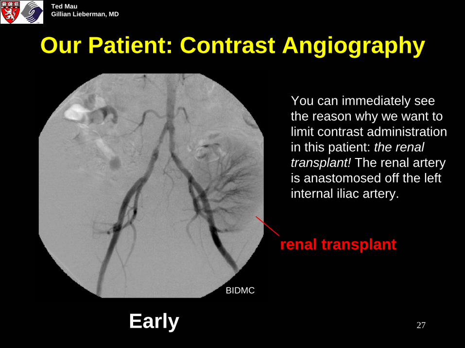
Our Patient: Contrast Angiography
Early
You can immediately see the reason why we want to limit contrast administration in this patient: the renal transplant! The renal artery is anastomosed off the left internal iliac artery.
BIDMC
renal transplant
Ted MauGillian Lieberman, MD

28
Our Patient: Contrast Angiography
Late
A little later: Now the remnants of the vascular supply to his first, failed renal transplant also becomes visible, off the right internal iliac artery. This patient relies solely on his second renal transplant!
Note the high grade stenosis in the right common iliac artery and the two low grade stenoses in the left common iliac artery.
BIDMC
failed renal transplant
Ted MauGillian Lieberman, MD

29
Our Patient: MRA
The MRA 3D reconstruction clearly shows the vasculature supplying the left renal transplant and the common iliac stenoses. Let’s take a closer look….
BIDMC
Ted MauGillian Lieberman, MD

30
CA vs. MRA: Aorto-Iliac
BIDMC
CA MRA
Ted MauGillian Lieberman, MD

31
MRA: Popliteal
BIDMC
Note 1. the high grade stenosis in the right popliteal artery proximal to the origin of the anterior anterial tibial artery, and 2. the lack of flow in the right posterior tibial artery immediately after its origin. This explains the non-healing right heel uncer.
1
2
Ted MauGillian Lieberman, MD
32
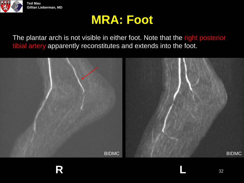
MRA: Foot
R LBIDMC BIDMC
The plantar arch is not visible in either foot. Note that the right posterior tibial artery apparently reconstitutes and extends into the foot.
Ted MauGillian Lieberman, MD

33
MRA vs. CA: Advantages
From: Baum & Carpenter, in Abram’s Angiography, 4th Ed. (1997)
One advantage of MRA is its potential to provide better definition of runoff vessels distal to a long segment of stenosis:
CA: Apparently occluded left common iliac artery
CA: No runoff vessels seen MRA: Three vessels seen
This patient does have flow to the lower leg in all 3 vessels as demonstrated by MRA. The lack of visualization on CA is because the contrast agent was not concentrated enough or did not arrive in the ankle quickly enough to be visualized on the X-ray.
Ted MauGillian Lieberman, MD

34
MRA vs. CA: Disadvantages
• Artifact problems: There is no blockage. The “gap” is due to a metallic stent artifact.
From: Baum & Carpenter, Chapter 72in Abram’s Angiography, 4th Ed. (1997)
Metal stent
Ted MauGillian Lieberman, MD

35
MRA vs. CA: Disadvantages
• Artifact problems (e.g. metal, movement)
• Difficulty in imaging certain segments: The Fem-Fem bypass was patent and functioning but the transverse direction of flow was not imaged on MRA.
From: Baum & Carpenter, Chapter 72in Abram’s Angiography, 4th Ed. (1997)
Fem-fem bypass not visualized on MRA because flow is in the plane of acquisition and the signals are saturated
Ted MauGillian Lieberman, MD
36
MRA vs. CA: Disadvantages
• Artifact problems (e.g. metal, movement)
• Difficulty in imaging certain segments
• Overestimation of severity of stenoses (due to local turbulence and resulting saturation)
• Long examination time
• Patient intolerance (e.g. claustrophobia, pace maker)
Ted MauGillian Lieberman, MD

37
Will MRA replace CA in the evaluation of LE arterial insufficiency?
• MRA may be more cost-effective1
• Some centers have switched over to MRA• MRA is a viable substitute in certain patients2
• As radiologists gain experience with MRA and the technology improves, MRA will gain wider acceptance
Ref: 1. Levy et al. J.Vasc Surg 28:995, 1998.2. Quinn et al. Radiology 206:693, 1998.
Ted MauGillian Lieberman, MD

38
Our Patient: Bilateral Iliac Stenting
pre post
Based on the MRA evaluation, it was decided to treat the high grade stenosis in the right common iliac artery with an endovascular stent. However, the left common iliac artery was also stented to avoid vascular steal from the renal transplant.
Ted MauGillian Lieberman, MD

39
ReferencesGood introductory articles and chapters:•Sheppard, S. Radiological Clinics of North America 33:91, 1995 •Baum & Carpenter, Chapter 72, in Abram’s Angiography, 4th Ed.,1997
MRA vs. CA:•Levy et al. J.Vasc Surg 28:995, 1998.•Quinn et al. Radiology 206:693, 1998.•Prince, M. Radiology 206:592, 1998.•Cambria, Chapter 14 in Magnetic Resonance Angiography: A Practical Approach, 1995.
Ted MauGillian Lieberman, MD

40
Acknowledgement
Dr. Wayne MonskyDr. Steve ReddyDr. Elvira LangLarry Barbaras and Ben Crandall our Webmasters
Ted MauGillian Lieberman, MD