mpmc powertech corp. lighting tower mlt8kl …resourcewebsite.singoo.cc/15296455582604495/en/pdf...1...
TRANSCRIPT

1
MPMC POWERTECH Corp.
Lighting Tower MLT8KL-1H/MLT8KL-2H
OPERATION AND MAINTENANCE MANUAL
This manual contains important safety information and must be made available to personnel who operate and maintain this machine.
NO : 42007100 REV : A DATE : January 2011

1
TABLE OF CONTENTS 1
TABLE OF CONTENTS ………………………………………………….………... 1 FOREWORD ………………………..……………………………………….………. 2 WARRANTY …………………………………………………………………….…… 3 DECALS ……………………………………………………………………….…….. 4 SAFETY …………………………………………………………………….………… 7 GENERAL INFORMATION ………………………………………………….…….... 13 OPERATION INSTRUCTIONS ……………………………………………..…..… 16 MAINTENANCE …………………………………….………………………...…….. 23 ELECTRICAL SYSTEMS ……………………….…………………….………..….. 32 CONTROLLER OPERATION ……………………..………………………….…… 33 FAULT FINDING ……………………………………………….…………………… 40

2
2 FOREWORD
The contents of this manual are considered to be proprietary and confidential to MPMC and should not be reproduced without the prior written permission of MPMC.
Nothing contained in this document is intended to extend any promise, warranty or representation, expressed or implied, regarding the MPMC products described herein. Any such warranties or other terms and conditions of sale of products shall be in accordance with the standard terms and conditions of sale for such products, which are available upon request.
This manual contains instructions and technical data covering all routine operation and scheduled maintenance tasks by operation and maintenance staff. Major overhauls are outside the scope of this manual and should be referred to an authorized MPMC service department.
The design specification of this machine is according to the EC directives.
All components, accessories, pipes and connectors added to the machine should be:
Of good quality, procured from a reputable manufacturer and, wherever possible, be of a type approved by MPMC.
Accompanied with instructions for safe installation, operation and maintenance.
Details of approved equipment are available from MPMC Service departments.
The use of repair parts / lubricants / fluids other than those included in the MPMC approved parts list may create hazardous conditions over which MPMC has no control. Therefore MPMC cannot be held responsible for equipment in which non-approved repair parts are installed.
MPMC reserves the right to make changes and improvements to products without notice and without incurring any obligation to make such changes or add such improvements to products sold previously.
The intended uses of this machine are outlined below and examples of unapproved usage are also given, however MPMC cannot anticipate every application or work situation that may arise.
The use of the machine in any of the situation types listed in table 1:− a) Is not approved by MPMC, b) May impair the safety of users and other
persons, and c) May prejudice any claims made against
MPMC. TABLE 1
Use of the machine exceeding the ambient temperature range specified in the GENERAL INFORMATION SECTION of this manual.
This machine is not intended and must not be used in potentially explosive atmosphere, including situations where flammable gases or vapors may be present.
Use of the machine fitted with non MPMC approved components / lubricants / fluids.
Use of the machine with safety or control components missing or disabled.
GENERATOR Use of the generator to supply load(s) greater than those specified.
Use of unsafe or unserviceable electrical equipment connected to the generator.
Use of electrical equipment: (a) Having incorrect voltage and/or frequency ratings. (b)Containing computer equipment and/or similar electronics.
The company is not liable for errors in translation of this manual from the original English version.
COPYRIGHT 2011 Millennium Power Manufacturing Corp.

3
WARRANTY 3
The warranty Period is based on the purchasing date and operation time. The one which is due first is used as the criterion, unless different specific regulations are made in this manual or in relevant commercial contracts.
·1000 working hours, or ·Twelve months after the purchase date, or ·Fifteen months since the generating sets leave the factory.
The time which occurs first is used as the criterion.
MPMC will provide a new part or repaired part, at its sole discretion, in place of any part that is found to be defective in material and workmanship during the period described above. Such parts will be repaired or replaced without charge to the initial user during normal working hours at the place of business of an MPMC distributor authorized to sell the equipment or other establishment authorized by MPMC. MPMC will log the engine serial numbers with the originating OEM and the MPMC alternators.
The above warranties do not apply to failures occurring as a result of abuse; misuse, negligent repairs, corrosion, erosion and normal wear and tear, alterations or modifications made to the product without express written consent of MPMC; or failure to follow the recommended operating practices and maintenance procedures as provided in the product’s operating and maintenance publications.
Accessories or equipment furnished by MPMC, but manufactured by others, including, but not limited to, engines, tires, batteries, electrical equipment, hydraulic transmissions, carriers, shall carry only the manufacturer’s warranty, which MPMC can lawfully assign to the initial user.
This warranty policy applies to all the products sold by Millennium Power Manufacturing Corp. to the distributors or the end users, regardless where the products are purchased. But only the customers who have commercial contract with Millennium Power Manufacturing Corp. can enjoy the warranty, the end user can enjoy warranty from the equipment supplier.
MPMC After-sales Department, authorized after-sales service centers and your local distributor are committed to providing you with superb service. If you have any problem about MPMC products or need more help, please contact MPMC After-sales Department as following: Millennium Power Manufacturing Corp.
No.111 Luda Rd. Luyuan Industrial Zone Pudong Shanghai 201322 China Tel: +86 21 60970158 Fax: +86 21 60970155 Email: [email protected]

4
4 DECALS
GRAPHIC FORM AND MEANING OF ISO SYMBOLS
Prohibition / Mandatory Information / Instructions Warning
WARNING: Electrical shock risk
WARNING − Hot surface. WARNING − Hot and harmful
exhaust gas.
WARNING − Pressurized vessel.
WARNING - Pressurized component or system
WARNING - Flammable liquid.
WARNING − Maintain correct tyre pressure. (Refer to the GENERAL INFORMATION
section of this manual).
WARNING − Before connecting the tow bar or
commencing to tow consult the operation and
maintenance manual.
WARNING − For operating temperature below 0℃,
consult the operation and maintenance manual.
5
DECALS 5
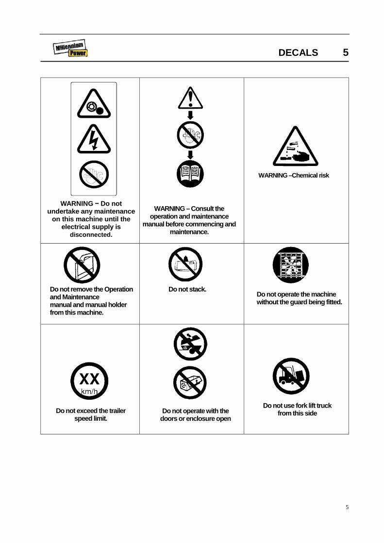
WARNING − Do not undertake any maintenance
on this machine until the electrical supply is
disconnected.
WARNING – Consult the operation and maintenance
manual before commencing and maintenance.
WARNING –Chemical risk
Do not remove the Operation and Maintenance manual and manual holder from this machine.
Do not stack. Do not operate the machine without the guard being fitted.
Do not use fork lift truck from this side Do not exceed the trailer
speed limit. Do not operate with the
doors or enclosure open

6
6 DECALS
Use fork lift truck from this side only.
Emergency stop Tie down point
Lifting point On (power) Off (power)
Read the Operation and Maintenance manual before
operation or maintenance of this machine is undertaken.
When parking use prop stand, handbrake and
wheel chocks.
No naked flames
Diesel fuel No open flame
Parking brake. Rough Service Designation. Wet Location Operation.
Warning: Ultra violet radiation. Can cause serious skin burn
and eye inflammation. Do not operate lights with missing or broken lens.
Do not operate if glass bulb is broken or punctured.
Oil drain.
Replace any cracked protective shield.

7
SAFETY 7 WARNINGS
Warnings call attention to instructions which must be followed precisely to avoid injury or death.
CAUTIONS Cautions call attention to instructions which must
be followed precisely to avoid damaging the product, process or its surroundings.
NOTES Notes are used for supplementary information.
General Information
Never operate the unit without first observing all safety warnings and carefully reading the operation and maintenance manual shipped from the factory with this machine.
Ensure that the operator reads and understands the decals and consults the manuals before maintenance or operation.
Ensure that the Operation and Maintenance manual, and the manual holder, are not removed from the machine.
Ensure that maintenance personnel are adequately trained, competent and have read the Maintenance Manuals.
This machine is not designed for operating life sustaining equipment. It is equipped with a safety shutdown system that will cause the machine to stop operating whenever a shutdown condition is present.
Hazards may exist on the jobsite should this unit shutdown automatically and all lamps be extinguished. Personnel should be advised of this and have additional lighting.
Hot pressurized fluid − remove cap slowly to relieve PRESSURE from hot radiator. Protect skin and eyes. HOT water or steam and chemical additives can cause serious personal injury.
Electrical shock hazard will cause severe injury or death. Do NOT operate the place light tower under electric power lines.
Improper operation of this machine can result in severe injury or death.
Hazardous Voltage can cause serious injury or death.
Never inspect or service the unit without first disconnecting battery cable(s) to prevent accidental starting.
Wear eye protection while cleaning unit with compressed air, to prevent debris from injuring eyes.
Do not enter ballast box while engine is running. Do not steam clean ballast box. Capacitor/Ballast can cause severe injury.
Do not operate lights with broken or missing lens or broken glass bulb. Ultra violet radiation can cause serious skin burn and eye inflammation.
Do not place hand in tower recess while tower is being lowered or raised. Pinch points can cause severe injury.
Ground equipment in accordance with applicable codes. (Consult local electrician).
Do not operate electrical equipment while standing in water, on wet ground, with wet hands or shoes.
Electrical ground/earth.

8
Use extreme caution when working on electrical components. Battery voltage (12V) is present unless the battery cables have been disconnected. Higher voltage (potentially 500 volts) is present at all times when the engine is running.
Always treat electrical circuits as if they were energized.
Before attempting any repair service, disconnect all leads to electrical power loads.
Do NOT connect or disconnect lamps while the
engine is running. Make sure that all protective covers are in place and that the canopy/doors are closed during operation.
The specification of this machine is such that the machine is not suitable for use in flammable gas risk areas. If such an application is required then all local regulations, codes of practice and site rules must be observed. To ensure that the machine can operate in a safe and reliable manner, additional equipment such as gas detection, exhaust spark
8 SAFETY arrestors, and intake (shut-off) valves may be
required, dependent on local regulations or the degree of risk involved.
A weekly visual check must be made on all fasteners/fixing screws securing mechanical parts. In particular, safety-related parts such as coupling hitch, drawbar components, road-wheels, and lifting bail should be checked for total security.
All components which are loose, damaged or unserviceable, must be rectified without delay.
This machine produces loud noise with the doors open or service valve vented. Extended exposure to loud noise can cause hearing loss. Always wear hearing protection when doors are open or service valve is vented.
Do not use petroleum products (solvents or fuels) under high pressure as this can penetrate the skin and result in serious illness. Wear eye protection while cleaning unit with compressed air to prevent debris from injuring eye(s).
Rotating fan blade can cause serious injury. Do not operate without guard in place.
Use care to avoid contacting hot surfaces (engine exhaust manifold and piping, air receiver and air discharge piping, etc.).
WARNING: Under no circumstances should volatile liquids such as Ether be used for starting this machine.
Never operate unit with guards, covers or
screens removed. Keep hands, hair, clothing, tools blow gun tips, etc. well away from moving parts.
Do not alter or modify this machine.
Materials
The following substances may be produced during the operation of this machine:
. brake lining dust
. engine exhaust fumes
AVOID INHALATION
Ensure that adequate ventilation of the cooling system and exhaust gases is maintained at all times.
The following substances are used in the manufacture of this machine and may be hazardous to health if used incorrectly:
engine lubricant preservative grease rust preventative diesel fuel battery electrolyte
AVOID INGESTION, SKIN CONTACT AND INHALATION OF FUMES
Safety data sheets for engine lubricants should be obtained from the lubricant supplier.
Never operate the engine of this machine inside a building without adequate ventilation. Avoid breathing exhaust fumes when working on or near the machine.
This machine may include such materials as oil, diesel fuel, antifreeze, brake fluid, oil/air filters and batteries which may require proper disposal when performing maintenance and service tasks. Contact local authorities for proper disposal of these materials.
When recycling or disposing of any electrical components, light bulbs etc., do not mix with general waste.

9
There is a separate collection system for used electronic products in accordance with legislation that requires proper treatment, recovery and recycling.
Please contact your local authorities for the correct method of disposal or recycling
SAFETY 9 Battery
A battery contains sulphuric acid and can give off gases which are corrosive and potentially explosive. Avoid contact with skin, eyes and clothing. In case of contact, flush area immediately with water.
DO NOT ATTEMPT TO SLAVE START A FROZEN BATTERY SINCE THIS MAY CAUSE IT TO EXPLODE.
Exercise extreme caution when using booster
battery. To jump battery, connect ends of one booster cable to the positive (+) terminal of each battery. Connect one end of other cable to the negative (−) terminal of the booster battery and other end to a ground connection away from dead battery (to avoid a spark occurring near any explosive gases that may be present). After starting unit, always disconnect cables in reverse order.
Radiator Hot engine coolant and steam can cause injury.
Ensure that the radiator filler cap is removed with due care and attention.
Do not remove the pressure cap from a HOT radiator. Allow radiator to cool down before removing pressure cap.
Generator sets The generator set is designed for safety in use.
However, the responsibility for safe operation rests with those who install, use and maintain it. The following safety precautions are offered as a guide, which, if conscientiously followed, will minimize the possibility of accidents throughout the useful life of this equipment.
Emergency Stop Controls
Important Note:− In addition to the key
operated emergency stop control on the main control panel, a second control is provided at the socket control panel in the event of electrical hazards associated with generator operation. Use this second control to immediately isolate all electrical power to all sockets, then use the key control to stop the engine.
Operation of the generator must be in accordance with recognised electrical codes and local health and safety codes.
The generator set should be operated by those who have been trained in its use and delegated to do so, and who have read and understood the operation manual. Failure to follow the instructions, procedures and safety precautions in the manual may increase the possibility of accidents and injuries.
Do not start the generator set unless it is safe to do so. Do not attempt to operate the generator set with a known unsafe condition.
Fit a danger notice to the generator set and render it inoperative by disconnecting the battery and disconnecting all ungrounded conductors so others who may not know of the unsafe condition will not attempt to operate it until the condition is corrected.
The generator set should only be used with the earth point connected directly to the general earth/ground mass. An earth spike kit is available as an optional extra for this purpose (refer to the parts catalogue).
Do not make contact with electrically energized
WARNING: DO NOT OPERATE THE MACHINE UNLESS IT HAS BEEN SUITABLY EARTHED.

10
parts of the generator set and/or interconnecting cables or conductors with any part of the body or with any non-insulated conductive object.
Make sure the generator set is effectively grounded in accordance with all applicable Regulations prior to attempting to make or break load connections and prior to attempting operation.
10 SAFETY Keep all parts of the body and any hand-held
tools or other conductive objects, away from exposed live parts of the generator set engine electrical system. Maintain dry footing, stand on insulating surfaces and do not contact any other portion of the generator set when making adjustments or repairs to exposed live parts of the generator set engine electrical system.
Close and lock all access doors when the generator set is left unattended.
Do not use extinguishers intended for Class A or Class B fires on electrical fires. Use only extinguishers suitable for class BC or class ABC fires.
Keep the towing vehicle or equipment carrier, the light tower, tools and all personnel at least 3 metres from all power lines and buried power cables.
Attempt repairs only in clean, dry, well lighted and ventilated areas. Connect the generator set only to loads and/or electrical systems that are compatible with its electrical characteristics and that are within it’s rated capacity.
Transport When loading or transporting machines, ensure
that the specified lifting and tie down points are used.
When loading or transporting machines ensure that the towing vehicle, its size, weight, towing hitch and electrical supply are all suitable to provide safe and stable towing at speeds either, up to the legal maximum for the country in which it is being towed or, as specified for the machine model if lower than the legal maximum.
Ensure that the maximum trailer weight does not exceed the maximum gross weight of the
machine (by limiting the equipment load), limited by the capacity of the running gear.
Note:
Gross mass (on data plate) is for the basic machine and fuel only, excluding any fitted options, tools, equipment and foreign materials.
Before towing the machine, ensure that:-
the tyres and towing hitch are in a serviceable condition.
the canopy is secure. all ancillary equipment is stored in a safe and
secure manner. the brakes and lights are functioning correctly
and meet necessary road traffic requirements. break-away cables/safety chains are connected
to the towing vehicle.
The machine must be towed in a level attitude in order to maintain correct handling, braking and lighting functions. This can be achieved by correct selection and adjustment of the vehicle towing hitch and, on variable height running gear, adjustment of the drawbar.
To ensure full braking efficiency, the front (towing eye) section must always be set level.
When adjusting variable height running gear:-
Ensure front (towing eye) section is set level
When raising towing eye, set rear joint first, then front joint.
When lowering towing eye, set front joint first, then rear joint.
After setting, fully tighten each joint by hand and then tighten further to the next pin. Refit the pin.
When parking always use the handbrake and, if

11
necessary, suitable wheel chocks.
Make sure wheels, tyres and tow bar connectors are in safe operating condition and tow bar is properly connected before towing.
Do not store or transport hazardous or combustible materials in or on this unit.
Do not suspend this machine with other equipment hanging from the running gear.
SAFETY 11
Safety chains / connections and their adjustment
The legal requirements for the joint operation of the breakaway cable and safety chains are as yet unidentified by 71/320/EEC or UK regulations. Consequently we offer the following advice / instructions.
Where brakes only are fitted:
a) Ensure that the breakaway cable is securely coupled to the handbrake lever and also to a substantial point on the towing vehicle.
b) Ensure that the effective cable length is as short as possible, whilst still allowing enough slackness for the trailer to articulate without the handbrake being applied.
Where brakes and safety chains are fitted:
a) Loop the chains onto the towing vehicle using the towing vehicle hitch as an anchorage point, or any other point of similar strength.
b) Ensure that the effective chain length is as short as possible whilst still allowing normal articulation of the trailer and effective operation of the breakaway cable.
Where safety chains only are fitted:
a) Loop the chains onto the towing vehicle using the towing vehicle hitch as an anchorage point, or any other point of similar strength.
b) When adjusting the safety chains there should be sufficient free length in the chains to allow normal articulation, whilst also being short enough to prevent the tow bar from touching the ground in the event of an accidental separation of the towing vehicle from the trailer.
Before towing
Make sure wheels, tires and tow bar connectors are in safe operating condition and tow bar is properly connected before towing.
Store the front outriggers and all jacks. To secure each jack handle, wrap the jack positioning pin chain around the handle to keep it from being damaged during towing.
Towing
Do not tow this unit with a vehicle whose towing capacity is less than the unit gross weight shown in General Data.
Do not exceed maximum speed of 50km/h (or local legal maximum, if lower) when towing unit.
Welding
CAUTION: Do not tow or move with mast extended.

12
Prior to any welding, disconnect alternator relays, voltage regulator, meters, circuit breakers and battery cables. Open all circuit breakers, and remove any external connections. Connect the welding ground as close as possible to the area being welded.
Mast Operation
Before and during all mast operation, ensure that the area is clear of persons and obstructions over a 2m radius and that there are no obstructions overhead. When the mast is fully extendedor is prevented from extending further, immediately
release the control switch, to ensure that no cable over tension occurs.
Check that no person is behind the machine (within 10m) while the tower is raised or lowered.
12 SAFETY
The unit must have all outriggers extended and
be level before raising mast.(use the level bubble on the top of the unit to ensure it is level).
DO NOT climb on tower. Perform repairs and
adjustments with the tower in the down (transport)

13
position.
Damaged cables may break during tower operation allowing the tower to fall. Do not operate tower with damaged cables. Replace damaged cables.
Lamps
Inspect lamps and replace broken or missing lamp lens or punctured glass bulbs. Do NOT operate lights with broken or missing lens or broken glass bulb.
Flammable fuels
This machine is fully bunded to contain leakages and spillages, which occur within the machine enclosure
The bund will contain all fluids normally installed in the machine, plus an additional 10%. Drain plugs for the bunded base are located underneath the unit.
The machine must only be operated when leveled.
Drains for engine water, engine oil and fuel tank are located at the rear right corner of the machine.
Draining of contaminated fluids
Contaminated fluid must be removed by authorized person only.
Captured fluids can be drained from the bund by removal of the plug at the rear base of the frame. This plug must be replaced after draining.
Drainage of machine fluids
During maintenance operations, drain machine fluids using the drain ports indicated. Disposal of contaminated fluids from bund
Contaminated fluids removed from bund, must be disposed to designated containers only
GENERAL INFORMATION 13
FIXED HEIGHT RUNNING GEAR
WARNING: Major leakages or spillages must be drained before the machine is towed.
14
14 GENERAL INFORMATION
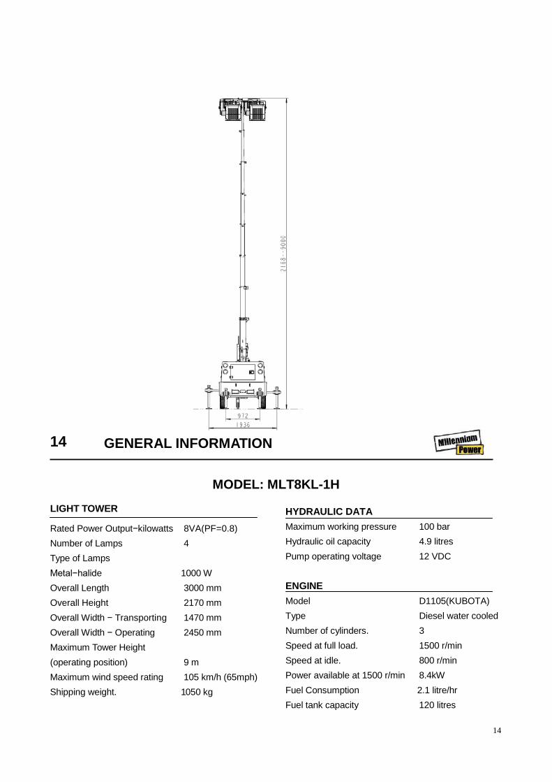
MODEL: MLT8KL-1H
LIGHT TOWER
Rated Power Output−kilowatts 8VA(PF=0.8) Number of Lamps 4 Type of Lamps Metal−halide 1000 W Overall Length 3000 mm Overall Height 2170 mm Overall Width − Transporting 1470 mm Overall Width − Operating 2450 mm Maximum Tower Height (operating position) 9 m Maximum wind speed rating 105 km/h (65mph) Shipping weight. 1050 kg
HYDRAULIC DATA Maximum working pressure 100 bar Hydraulic oil capacity 4.9 litres Pump operating voltage 12 VDC ENGINE Model D1105(KUBOTA) Type Diesel water cooled Number of cylinders. 3 Speed at full load. 1500 r/min Speed at idle. 800 r/min Power available at 1500 r/min 8.4kW Fuel Consumption 2.1 litre/hr Fuel tank capacity 120 litres

15
Electrical system. 12V negative earth Alternator 60 amps @ 12 Volts ALTERNATOR(GENERATOR) Type LYGD164B Voltage 220 V Frequency 50 Hz Power 6.5 kW Voltage stability +/− 6% Standard socket outlet 2 x 10 Amps SOUND LEVEL DATA
In compliance with 86/188/EEC. Average sound pressure level at 10m to 79/113/EEC.* 88 LWA (*Machine only : at maximum load in open site conditions) WHEELS AND TYRES
Number of wheels. 2 Tyre size. 165 R14C Tyre pressure. 3,5 bar (50 PSI)
GENERAL INFORMATION 15
MODEL: MLT8LPM-2H
LIGHT TOWER
Rated Power Output−kilowatts 7.5 kW Number of Lamps 4 Type of Lamps Metal−halide 1000 W Overall Length 3000 mm Overall Height 2170 mm Overall Width − Transporting 1470 mm Overall Width − Operating 2450 mm Maximum Tower Height (operating position) 9 m Maximum wind speed rating 105 km/h (65mph) Shipping weight. 1050 kg
HYDRAULIC DATA
Maximum working pressure 100 bar Hydraulic oil capacity 4.9 litres Pump operating voltage 12 VDC ENGINE
Model D1105(KUBOTA) Type Diesel water cooled Number of cylinders. 2 Speed at full load. 1800 r/min Speed at idle. 1200 r/min
Further information may be obtained by request through mpmc customer services department.

16
Power available at 1800 r/min 9.5kW Fuel Consumption 2.4 litre/hr Fuel tank capacity 120 litres Electrical system. 12V negative earth Alternator 60 amps @ 12 Volts ALTERNATOR(GENERATOR)
Type LYGD164B Voltage 220 V Frequency 60 Hz Power 7.5 kW Voltage stability +/−1% Standard socket outlet 2 x 10 Amps SOUND LEVEL DATA
In compliance with 86/188/EEC. Average sound pressure level at 10m to 79/113/EEC.* 88 LWA (*Machine only : at maximum load in open site conditions) WHEELS AND TYRES
Number of wheels. 2 Tyre size. 165 R14C Tyre pressure. 3,5 bar (50 PSI)
16 OPERATING INSTRUCTION COMMISSIONING
Upon receipt of the unit, and prior to putting it into service, it is important to strictly adhere to the instructions given below PRIOR TO STARTING.
Ensure that the operator reads and understands the decals and consults the manuals before maintenance or operation.
Ensure that the position of the emergency stop device is known and recognized by its markings. Ensure that it is functioning correctly and that the method of operation is known.
Running gear drawbar − Machines are shipped to some areas with the drawbar removed. Fitting involves four nuts / bolts to secure the drawbar to the axle and two bolts to fit the drawbar to the front of the
machine with the saddle and spacer block.
Support the side of the machine, fit the wheel chocks to stop the machine moving and attach the drawbar. Refer to the torque value table in the MAINTENANCE section of this manual for the correct torque values.
Fit the prop stand and coupling. Remove the supports and set the machine level.
Before towing the unit, ensure that the tyre pressures are correct (refer to the GENERAL INFORMATION section of this manual) and that the handbrake is functioning correctly (refer to the MAINTENANCE section of this manual). Before
CAUTION: This is a safety critical procedure. Double check
the torque settings after assembly (see table)
Further information may be obtained by request through mpmc customer services department.

17
towing the unit during the hours of darkness, ensure that the lights are functioning correctly (where fitted).
Ensure that all transport and packing materials are discarded.
Ensure that the correct fork lift truck slots or marked lifting / tie down points are used whenever the machine is lifted or transported.
When selecting the working position of the machine ensure that there is sufficient clearance for ventilation and exhaust requirements, observing any specified minimum dimensions (to walls, floors etc.).
Adequate clearance needs to be allowed around and above the machine to permit safe access for specified maintenance tasks.
Ensure that the machine is positioned securely and on a stable foundation. Any risk of movement should be removed by suitable means, especially to avoid strain on any rigid discharge piping.
Attach the battery cables to the battery(s) ensuring that they are tightened securely. Attach the negative cable before attaching the positive cable.
SET−UP (PRIOR TO RAISING MAST)
1. Make sure the unit is detached from towing vehicle.
2. Make sure the parking brake is correctly engaged.
3. Inspect cables. Cables should not be frayed, cut, abraded, or otherwise damaged. Replace
damaged cables.
4. Check hydraulic oil level. Fill if necessary / as required.
5. Ensure no obstruction is overhead within 15 meters.
6. Be sure lamps are secure on cross bar and position as desired.
7. Extend all outriggers fully and insert locking pins fully. Ensure drawbar jack and all outrigger and/or jacks are firmly in contact with ground.
8. Level unit using jacks and bubble level indicator.
9. Jacks must support entire unit weight (tyres off the ground).
BEFORE STARTING THE ENGINE Before starting the engine, carry out the following checks:
1. Engine oil level: Add as specified.
2. Engine coolant level: Add as specified.
3. Fuel/water filter: Drain any accumulation of water. Clean or replace element as required.
4. Air cleaner service indicator (if equipped): Service when showing “red”
5. Fuel level in tank: Fill, using CLEAN DIESEL fuel, at the end of the day to minimize condensation.
OPERATING INSTRUCTION 17 6. Battery: Keep terminals clean and lightly greased.
7. Engine belts and hoses: Check for proper fit and/or damage.Service as required.
8. Air Vents/Grilles: Both engine radiator and
generator cooling air Check for obstructions (leaves, paper, etc.).
9. Visual inspection: Check for excessive fluid leaks, evidence of arcing around control panel, loose wire-routing clamps, etc.
CAUTION: Call a qualified person to make electrical repairs.

18
18 OPERATING INSTRUCTION
1 2 4 10 9 11

19
OPERATING INSTRUCTION 19 STARTING THE ENGINE
1. The Lamp power breaker should be “OFF”. 2. Turn the control system power switch “ON”. 3. Keep pressing the engine start button for 3-5
seconds to start the engine. 4 Release the start button as soon as the engine
continues to run. 5. Allow the engine to warm up for 3 to 5 minutes. 6. Turn the main power breaker on.
7. The Lamp power breaker may now be switched “ON”.
Reference Description Function
1 OFF
Stop the engine Reset when alarm
2 RUN
Run/start the engine.
3 Fuel level meter Fuel level display
4 Control system Power switch Protects control system circuits
5 Timer Auto stop timer control.
6 Main power breaker General power control (for all 4 lamps)
7 Lamp power breaker Controls individual lamps.
8 Outlet Socket circuit breaker
9 Mast raise button Operates to raise the mast
10 Mast down button Operates to lower the mast
11 Control panel lighting LED Illuminates the switches at night (always on)
3 5 6 7 8
WARNING: Keep side doors closed for optimum cooling and safety of unit while running.
NOTE: The engine in this unit is protected with sensors for high coolant temperature and low oil pressure. Should either of these conditions occur, the engine will automatically stop causing a loss of power to all lamps. Before restarting the unit, check the fuel level and engine/radiator thoroughly and correct the problem. The lamps should not be restarted in 15 minutes.

20
SOCKET OUTLETS With engine running
1. Turn on the socket breakers.
2. Plug the equipment into the sockets.
STOPPING THE ENGINE while lights are ON
1. Turn the Lamps “OFF” by switching the main breaker (6) “OFF”
2. Turn the socket breakers “OFF” if they are on.
3. Turn the main power breaker “OFF”.
4. Press the stop button to stop the engine.
5. Turn control system power “OFF”.
20 OPERATING INSTRUCTION
NOTE: If the lights are turned off, they should not be restarted for 15 minutes.
UNIT SHOWN WITH MAST IN TRANSPORT POSITON
Standard power socket outlet (10A, 1Phase, 220V)
1 1
2
3

21
MAST OPERATION Raising the tower 1. Remove the transport straps and mast locks
2. Start the engine.
3. Use the mast control switch to raise the tower.
4. Lift the pin [2] & loosen the screw [3] to rotate
tower. Release the pin [2] & tighten the screw [3] after rotating the tower to the desired position.
Lowering the tower 1. Start the engine.
2. Switch the lamps off.
3. Loose the screw [3], lift the pin [2] to rotate mast. Release the pin [2] & tie the screw [3] after rotating the mast to the desired position.
4. Make sure that the pin has engaged and locked the mast in position.
5. Use the mast control switch to lower the mast to transport position
OPERATING INSTRUCTION 21 TOWING
1. Connect the machine to the vehicle.
2. Rotate the lamps to transport position and secure by fitting straps [1] around the lamp bodies.
3. Make sure that the tow vehicles hitch [5] is the
WARNING: Check that no person is behind the machine (within 10m) while the tower is raised or lowered.
Check that no obstruction is overhead.
Before operating the mast, inspect the cable for damage. Replace damaged cables if necessary.
Before and during all mast operation, ensure the area is clear of persons and obstructions within a 2m radius.
When the mast has reached its maximum travel height, immediately release the control switch, to avoid cable over tension.
WARNING: Make sure that the tow vehicle has a towing capacity of the weight of this unit as stated in “GENERAL INFORMATION” section of this manual.
NOTE: This unit is equipped with a mast lowering switch. When parking brake is released the mast will lower. Avoid towing with raised mast
WARNING: Beware of lamps lowering when operating under mast area.
WARNING: The lamp bodies may be HOT.
4 5
8 6 7
22
proper size to securely connect to the eye or coupler on the unit.
4. Check eye or coupler bolts for any looseness or wear. Tighten or replace as required.
5. Check the wheels.
6. Position the tow vehicle to align the hitch with the eye or coupler [5].
7. Stand aside while operating the jockey wheel [6] to seat the eye or coupler onto the hitch.
8. Secure the hitch.
9. Make sure outriggers and jacks are stored in transport position and the handles are secured by the chains.
10. Attach the brake actuator breakaway chain /cable [8].
11. Make sure the units towing lights are working properly, in accordance to the towing vehicle’s lighting as well as local regulations.
12. Connect the towing lighting plug. 13. Remove wheel chocks.
14. Release hand brake [4].
15. Check that the units brakes are operating correctly.
16. Unit is ready to be towed. LIFTING THE MACHINE Before lifting the machine, carry out the following checks:
1. No loose objects are stored inside or on top of the machine.
2. No additional equipment is hung onto or under the machine.
3. Any device used for lifting is rated at a minimum of 2000kg.
4. No personnel should be on or under the machine at any time during lifting.
Lifting can be done by either:
1. using the lifting eye on the top of the unit or
2. 2. Using the fork tynes at the rear of the unit
RE−STARTING AFTER AN EMERGENCY STOP If the machine has been switched off because of
a machine malfunction, then identify and correct the fault before attempting to re-start. Check the DSE controller for error messages.
If the machine has been switched off for reasons of safety, then ensure that the machine can be operated safely before re-starting.
Refer to the PRIOR TO STARTING and STARTING THE UNIT instructions earlier in this section before re-starting the machine.
MONITORING DURING OPERATION Should any of the safety shut-down conditions occur, the unit will stop. These are:
Low engine oil pressure
High engine water temperature
22 OPERATING INSTRUCTION DECOMMISSIONING When the machine is to be permanently decommissioned or dismantled, it is important to ensure that all hazard risks are either eliminated or notified to the recipient of the machine. In particular:-
Do not destroy batteries or components containing asbestos without disposing the materials safely.
Do not dispose of any pressure vessel that is not clearly marked with its relevant data plate information or rendered unusable by drilling, cutting etc.
Do not allow lubricants or coolants to be released into land surface or drains.
WARNING: Make sure the hitch is completely engaged to the tow vehicle and is secure. Failure to do so could result in serious personal injury.
Do not use the eye or coupler with any bent or otherwise damaged parts.

23
Do not dispose of a complete machine without documentation relating to instructions for its use.
MAINTENANCE 23

24
*Disregard if not appropriate for this particular machine.
(1) or 3000 miles/5000km whichever is the sooner (2) or as defined by local or national legislation C = Check (adjust, clean or replace as necessary) CBT =check before towing. CR = Check and report D = Drain
G = Grease
R=Replace T = Test W I =or when indicated if earlier. Refer to specific sections of the operation manual for more information.
MAINTENANCE SCHEDULE
Initial.
Daily Weekly
Hours Monthly / Hours km
(miles) Hours 200/400 1/− 3/250 6/500 12/1,000
850(500) 50 Engine Oil Level C *Radiator Coolant Level C Gauges/Lamps C *Air Cleaner Service Indicators C Fuel Tank (Fill at end of day) C *Fuel/Water Separator Drain C Oil Leaks C Fuel Leaks C Drain Water From Fuel Filters C Coolant Leaks C Header Tank Cap. C Fan/Alternator Belts C Battery Connections/Electrolyte C Tire Pressure and Surface C *Wheel Lug Nuts C Hoses (Oil, Air, Intake, etc.) C Automatic Shutdown System C Air Cleaner System C *Engine Rad/Oil Cooler Exterior C Fasteners, Guards C Air Cleaner Elements R/WI *Fuel/Water Separator Element R Engine Oil Change R R/− Engine Oil Filter R R/− *Water Pump Grease. R *Wheels (Bearings, Seals, etc.) C *Engine Coolant C

25
24 MAINTENANCE
Initial.
Daily Weekly
Hours Monthly / Hours km
(miles) Hours 200/400 1/− 3/250 6/500 12/1,000
850(500) 50 Fuel Filter Element −/R *Injection Nozzle Check C Shutdown Switch Settings T

26
*Disregard if not appropriate for this particular machine. (1) or 3000 miles/5000km whichever is the sooner (2) or as defined by local or national legislation C = Check (adjust, clean or replace as necessary) CBT =check before towing. CR = Check and report D = Drain G = Grease
R=Replace T = Test W I =or when indicated if earlier. Refer to specific sections of the operation manual for more information.
Do not tow this unit with a vehicle that has a towing capacity that is less than the unit gross weight shown in General Data.
MAINTENANCE 25 ROUTINE MAINTENANCE
This section refers to the various components which require periodic maintenance and replacement.
The SERVICE/MAINTENANCE CHART indicates the various components’ descriptions and the intervals when maintenance has to take place. Oil capacities, etc., can be found in the GENERAL INFORMATION section of this manual.
For any specification or specific requirement on service or preventative maintenance for the engine, refer to the Engine Manufacturer’s Manual.
Ensure that maintenance personnel are adequately trained, competent and have read the Maintenance Manuals.
Prior to attempting any maintenance work, ensure that:-
*Feed Pump Strainer Cleaning. C Coolant Replacement R *Valve Clearance Check C Lights (running, brake, & turn) CBT Pintle Eye Bolts CBT *Brakes C C *Brake linkage C Emergency stop T Fasteners C Running gear linkage G Running gear bolts(1) C Evidence of Arcing Around Elect. Terminals C Tower Cables C Nylon Guides / Slide check C Hydraulic Oil Level C R Loose Wire Routing Clamps C Proper Grounding Circuit C Wiring Insulation C Obstructions in Air Vents C Control Compartment (Interior) C Engine Shutdown System Switches (setting)
C
Exterior Finish As needed Engine Refer to Engine Operation Manual Decals Replace decals if removed, damaged or missing

27
the machine cannot be started accidentally or otherwise, by posting warning signs and/or fitting appropriate anti-start devices.
all residual electrical power sources (mains and battery) are isolated.
Prior to opening or removing panels or covers to work inside a machine, ensure that:-
anyone entering the machine is aware of the reduced level of protection and the additional hazards, including hot surfaces and intermittently moving parts.
the machine cannot be started accidentally or otherwise, by posting warning signs and/or fitting appropriate anti-start devices.
Prior to attempting any maintenance work on a running machine, ensure that:-
the work carried out is limited to only those tasks which require the machine to run.
the work carried out with safety protection devices disabled or removed is limited to only those tasks which require the machine to be running with safety protection devices disabled or removed.
all hazards present are known (e.g. pressurized components, electrically live components, removed panels, covers and guards, extreme temperatures, inflow and outflow of air, intermittently moving parts, safety valve discharge etc.).
appropriate personal protective equipment is worn.
loose clothing, jewelry, long hair etc. is made safe.
warning signs indicating that Maintenance Work is
in Progress are posted in a position that can be clearly seen.
Upon completion of maintenance tasks and prior to returning the machine into service, ensure that:-
The machine is suitably tested.
All guards and safety protection devices are refitted.
All panels are replaced, canopy and doors closed.
Hazardous materials are effectively contained and disposed of.
ELECTRICAL SYSTEM
Inspect the safety shutdown system switches and the instrument panel relay contacts for evidence of arcing and pitting. Clean where necessary.
Check the mechanical action of the components.
Check the security of electrical terminals on the switches and relays i.e. nuts or screws loose, which may cause local hot spot oxidation.
Inspect the components and wiring for signs of overheating i.e. discoloration, charring of cables, deformation of parts, acrid smells and blistered paint.
ELECTRICAL TERMINALS Check daily for evidence of arcing around the
electrical terminals
GROUNDING CIRCUIT Daily check that the grounding circuit is in
accordance with local code requirements. Check to ensure continuity between the grounding terminal, frame, generator and engine block.
WIRING INSULATION Daily check for loose, or frayed wiring insulation
or sleeving.
26 MAINTENANCE BATTERY
Keep the battery terminals and cable clamps clean and lightly coated with petroleum jelly to prevent corrosion.
The retaining clamp should be kept tight enough to prevent the battery from moving.
INSTRUMENTS
Inspect the instrument lamps, gauges and switches prior to start-up and during operation to ensure proper functioning.
CONTROL COMPARTMENT
Every six months or 500 hours with the unit “OFF”, perform visual inspection for loose connections, dirt, arcing, damage to electrical components.
TOWER CABLES
WARNING: Always disconnect the battery cables before performing any maintenance or service.

28
Each day the tower lifting cables should be inspected to ensure the ends are attached securely. The cables should be checked for fraying or other damage and replaced if damaged. Also the pulleys should be checked for unusual wear or damage and replaced if worn excessively or damaged.
WIRE ROUTING CLAMPS
Daily check for loose wire routing clamps. Clamps must be secure and properly mounted. Also check wiring for wear, deterioration and vibration abrasion.
TOWER GUIDES
Every month inspect all of the tower guides for proper operation. Clean sliding surfaces. Replace any missing or damaged parts before raising the tower.
ENGINE RADIATOR Check the coolant level in the radiator. The
coolant must cover the tubes in the top tank (approximately 1 inch high on a clean measuring rod, inserted down filler neck).
The engine coolant system is normally filled with a 50/50 mixture of water and ethylene glycol. This permanent type anti-freeze contains rust inhibitors and provides protection to−35℉ (−37℃). The use of such a mixture is recommended for both summer and winter operation.
It is recommended to test the freezing protection of the coolant every six months or prior to freezing temperatures. Replenish with a fresh mixture every twelve months.
Each month, inspect the radiator exterior for obstructions, dirt and debris. If present, blow water or compressed air containing a non-flammable solvent between the fins in a direction opposite the normal air flow. Should the radiator be clogged internally, reverse flushing, using a commercial product and the supplier’s recommended procedure, may correct the problem.
ENGINE PROTECTION SHUTDOWN SYSTEM
The operation of the engine protection shutdown system should be checked every month, or whenever it appears to be not operating properly. The three switches involved in this protective shutdown system are the engine coolant high temperature switch, the engine oil pressure switch and the low fuel level switch (optional).
The engine oil pressure switch prevents the engine from operating with low oil pressure. Once a month, remove a wire from the engine oil pressure switch to check the shutdown system for proper operation.
Test the engine oil pressure switch by removing it and connecting it to a source of controlled pressure while monitoring an ohmmeter connected to the switch terminals.
As pressure is applied slowly from the controlled source, the switch should close at 12 psi (84 kPa) and show continuity through the contacts. As the pressure is slowly decreased to 10 psi (70 kPa) the contacts should open and the ohmmeter should show a lack of continuity through the contacts. Replace a defective switch before continuing to operate the unit.
Once a year, the temperature actuated switch should be tested by removing it from the unit and placing it in a bath of heated oil. The engine coolant high temperature switch will require a temperature of approximately 220℉ (104℃) to actuate.
MAINTENANCE 27 AIR FILTER ELEMENTS
The air filter should be inspected regularly (refer to the SERVICE/MAINTENANCE CHART) and the element replaced when the restriction indicator shows red or every 6 Months (500 hours), whichever comes first. The dust collector box(es) should be
cleaned daily (more frequently in dusty operating conditions) and not allowed to become more than half full.
Removal
WARNING: Remove cap slowly to relieve Pressure from HOT radiator. Protect skin and eyes. Hot water or steam and chemical additives can cause serious personal injury.
CAUTION: Never operate the unit with a defective safety shutdown switch or by by−passing a switch.
CAUTION: Never remove and replace element(s) when the machine is running.

29
Clean the exterior of the filter housing and
remove the filter element by releasing the nut.
Inspection Check for cracks, holes or any other damage to
the element by holding it up to a light source, or by passing a lamp inside.
Check the seal at the end of the element and replace if any sign of damage is evident.
Reassembly Assemble the new element into the filter housing
ensuring that the seal seats properly.
Reset the restriction indicator by depressing the rubber diaphragm. Assemble the dust collector box parts, ensuring that they are correctly positioned.
Before restarting the machine, check that all clamps are tight.
VENTILATION Always check that the air inlets and outlets are
clear of debris etc.
COOLING FAN DRIVE
Periodically check that the fan mounting bolts in the fan hub have not loosened. If, for any reason, it becomes necessary to remove the fan or re-tighten the fan mounting bolts, apply a good grade of commercially available thread locking compound to the bolt threads and tighten to the torque value shown in the TORQUE SETTING TABLE later in this section.
The fan belt(s) should be checked regularly for wear and correct tensioning.
FUEL SYSTEM
The fuel tank should be filled daily or every eight hours. To minimize condensation in the fuel tank(s), it is advisable to top up after the machine is shut down or at the end of each working day. At six month intervals drain any sediment or condensate that may have accumulated in the tank(s).
FUEL FILTER WATER SEPARATOR The fuel filter water separator contains a filter
element which should be replaced at regular intervals (see the SERVICE/MAINTENANCE CHART).
LUBRICATION The engine is initially supplied with engine oil
sufficient for a nominal period of operation (for more information, consult the Engine section of this manual).
If, for any reason, the unit has been drained, it must be re-filled with new oil before it is put into operation.
ENGINE LUBRICATING OIL
The engine oil should be changed at the engine manufacturer’s recommended intervals. Refer to the Engine section of this manual.
ENGINE LUBRICATING OIL SPECIFICATION
Refer to the Engine section of this manual.
ENGINE OIL FILTER ELEMENT
The engine oil filter element should be changed at the engine manufacturer’s recommended intervals. Refer to the Engine section of this manual.
TYRES/TYRE PRESSURE See the GENERAL INFORMATION section of
this manual.
RUNNING GEAR/WHEELS
Check the wheel nut torque 20 miles (30 kilometres) after refitting the wheels. Refer to the TORQUE SETTING TABLE later in this section.
Lifting jacks should only be used under the axle.
The bolts securing the running gear to the chassis should be checked periodically for tightness (refer to the SERVICE/MAINTENANCE CHART for frequency) and re-tightened where necessary. Refer to the TORQUE SETTING TABLE later in this section.
28 MAINTENANCE RUNNING GEAR WHEEL BEARINGS
Wheel bearings should be packed with grease every 6 months. The type of grease used should conform to specification MIL−G−10924.
BRAKES
Check and adjust the brake linkage at 500 miles (850Km) then every 3000 miles (5000Km) or 3 months (whichever is the sooner) to compensate for any stretch of the adjustable cables. Check and
CAUTION: NEVER clean by blowing air inwards.
CAUTION: Always check the oil levels before a new machine is put into service.

30
adjust the wheel brakes to compensate for wear.
ADJUSTING THE OVERRUN BRAKING SYSTEM 1: Preparation
Jack up the machine
Disengage the handbrake lever [1].
Fully extend the draw bar [2] on the overrun braking system.
1 Handbrake lever
2 Draw bar and bellows
3 Handbrake lever pivot
4. Spring sleeve complete.
5 Brake cable
6 Breakaway Cable
Requirements:
During the adjustment procedure always start with the wheel brakes. Always rotate the wheel in the direction of forward movement.
Ensure that an M10 safety screw is fitted to the handbrake pivot.
The brake actuators must not be pre-tensioned − if necessary loosen the brake linkage [7] on the brake equalization assembly [8].
Check that brake actuators and cables [11] operate smoothly.
7 Brake linkage
8 Equalization assembly
9 Compression spring
10 Equalizer plate
11 Cable
MAINTENANCE 29
2. Brake Shoe Adjustment
CAUTION
The compression spring [9] must only be lightly pre-tensioned and when operating must never touch the axle tube.
Never adjust the brakes at the brake linkage [7].

31
12 Adjusting screw
13 Cable entry
Width across flats of adjusting screw [12]
Brake size Key width 60x35 / 200x50 SW 17 250x40 SW 19 300x60 SW 22
Tighten adjusting screw [12] clockwise until the
wheel locks.
Loosen adjusting screw [12] anti-clockwise (approx. ½ turn) until the wheel can be moved freely.
Slight dragging noises that do not impede the free movement of the wheel are permissible.
This adjustment procedure must be carried out as described on both wheel brakes.
When the brake has been adjusted accurately the actuating distance is approximately 5−8mm on the cable [11]
3: Compensator assembly adjustment Variable Height models
Fit an M10 safety screw to the handbrake pivot. Disconnect the handbrake cable [5] at one end.
Pre-adjust brake linkage [7] lengthways (a little play is permissible) and re-insert the cable [5], adjusting it to give a small amount of play.
Remove the M10 safety screw from the handbrake pivot.
All Models
Engage the handbrake lever [1] and check that the position of the equalizer plate [10] is at right angles to the pulling direction. If necessary correct the position of the equalizer plate [10] on the cables [11].
The compression spring [9] must only be slightly pre-tensioned and when engaged must not touch the axle tube.
4: Brake linkage adjustment
Adjust the brake linkage [7] lengthways without pre-tension..
Readjustment
Engage the handbrake lever [1] forcefully a number of times to set the brake.
Check the alignment of the equalization assembly [8], this should be at right angles to the pulling direction
Check the play in the brake linkage [7]
If necessary adjust the brake linkage [7] again without play and without pre-tensioning
There must still be a little play in cable [5] (Variable Height Only)
Check the position of the hand brake lever [1]. The start of resistance should be approximately 10−15mm above the horizontal position.
Check that the wheels move freely when the handbrake is disengaged.
Final test
Check the fastenings on the transmission system (cables, brake equalization system and linkage).
Check the handbrake cable [5] for a small amount of play and adjust if necessary (Variable height only)
Check the compression spring [9] for pre-tensioning.
Test run
If necessary carry out 2−3 test brake actions.
Test brake action
Check the play in brake linkage [7] and if necessary adjust the length of brake linkage [7] until there is no play.
30 MAINTENANCE
Apply the handbrake while rolling the machine

32
forward, travel of the handbrake lever up to 2/3 of maximum is allowed.
Re-adjusting the overrun braking system
Re-adjustment of the wheel brakes will compensate for brake lining wear. Follow the procedure described in 2: Brake Shoe Adjustment.
Check the play in the brake linkage [7] and re-adjust if necessary.
Important
Check the brake actuators and cables [11]. The brake actuators must not be pre-tensioned.
Excessive operation of the handbrake lever, which may have been caused by worn brake linings, must not be corrected by re-adjusting (shortening) the brake linkage [7].
Re-adjustment
The handbrake lever [1] should be engaged forcefully several times to set the braking system.
Check the setting of the brake equalization assembly [8], which should be at right angles to the pulling direction.
Check the play in the brake linkage [7] again, ensuring that there is no play in the brake linkage and that it is adjusted without pre-tension Check the position of the hand brake lever [1], cable [5] (with little play) and the compression spring [9] (only slight pre-tension). The start of resistance of the handbrake lever should be approximately 10−15mm above the horizontal position.
Final test
Check the fastenings on the transmission system (cables, brake equalization system and linkage).
Apply the handbrake while rolling the machine forward, travel of the handbrake lever up to 2/3 of maximum is allowed.
Check the handbrake cable [5] for a small amount of play and adjust if necessary (Variable height only)
Check the compression spring [9] for slight pre-tensioning.
GENERAL CLEANING INSTRUCTIONS Keeping the machine clean of any oil and dirt is
recommended for both appearance and maximum service life of the equipment. The frequency of cleaning will be dependent on local conditions and the severity and frequency of operation.
TORQUE VALUES TABLE 1
ft lbf Nm
Engine mounts to engine 29−35 39−47
Air filter to bracket 16−20 22−27
Autella clamp to exhaust 9−11 12−15
Enclosure 9−11 12−15
Drop Leg 53−63 72−85
Exhaust flange to manifold 17−21 23−28
Fan guard 9−11 12−15
Fan to hub 12−15 16−20
Running gear front to chassis 63−69 82−93
Running gear rear to chassis 63−69 82−93
Running gear drawbar to axle 29−35 39−47
Band clamp on hose 106−133 143−180
Wheel nuts 50−80 67−109
USE VALUES FROM TABLE 2 IF NOT SPECIFIED IN TABLE 1
MAINTENANCE 31
NOTE: Do not use high pressure water, steam or solvent on the exterior finish of the unit housing.
CAUTION: Check the wheel nut torque 20 miles (30 kilometres) after refitting the wheels (Refer to the TORQUE SETTING TABLE later in this section).
33
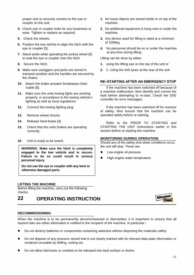
TABLE2 METRIC FASTENERS
CAPSCREW OR NUT
THREAD SIZE AND PITCH
NOMNAL DESIGN TORQUE PROPERTY GRADE8.8
(HEAD MARKING)
PROPERTY GRADE 10.9
(HEAD MARKING)
PROPERTY GRADE 12.9
(HEAD MARKING)
(Nm.) (FT-LBF) (Nm.) (FT-LBF) (Nm.) (FT-LBF)
M6×1.0 11 8 15 11 18 13
M8×1.25 26 19 36 27 43 31
M10×1.5 52 36 72 53 84 62
M12×1.75 91 67 126 93 147 109
M14×2 146 107 200 148 234 173
M16×2 226 166 313 231 365 270
M20×2.5 441 325 610 450 713 526
32 ELECTRICAL SYSETM
TYPICAL RECTANGULAR TORQUE PATTERN
TYPICAL SQUARE TORQUE PATTERN
TYPICALCIRCULAR TORQUE PATTERN

34
SCHEMATIC DIAGRAM FOR AC ELECTRICAL HARNESS
DSE3110 CONTROLLER OPERATION 33
35
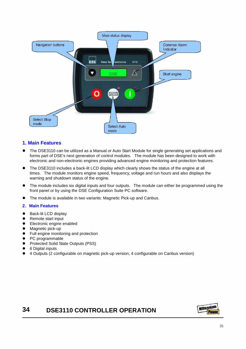
1. Main Features The DSE3110 can be utilized as a Manual or Auto Start Module for single generating set applications and
forms part of DSE's next generation of control modules. The module has been designed to work with electronic and non-electronic engines providing advanced engine monitoring and protection features.
The DSE3110 includes a back-lit LCD display which clearly shows the status of the engine at all times. The module monitors engine speed, frequency, voltage and run hours and also displays the warning and shutdown status of the engine.
The module includes six digital inputs and four outputs. The module can either be programmed using the front panel or by using the DSE Configuration Suite PC software.
The module is available in two variants: Magnetic Pick-up and Canbus.
2.Main Features Back-lit LCD display Remote start input Electronic engine enabled Magnetic pick-up Full engine monitoring and protection PC programmable Protected Solid State Outputs (PSS) 6 Digital inputs 4 Outputs (2 configurable on magnetic pick-up version, 4 configurable on Canbus version)
34 DSE3110 CONTROLLER OPERATION
36
3.Benefits Hours counter provides accurate information for monitoring maintenance and warranty periods Multiple engine parameters are monitored simultaneously Suitable for engine only applications Module can be configured to suit individual applications IP65/Nema 12 rating offers advanced resistance to water ingress (Gasket required) No need for additional metering equipment Wide range of engines can be specified Uses the DSE Configuration Suite PC Software for simplified programming 4.QUICKSTART GUIDE This section provides a quick start guide to the module’s operation.
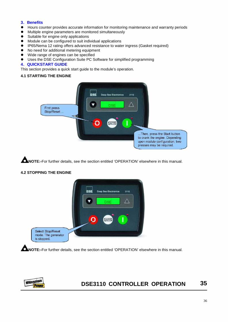
4.1 STARTING THE ENGINE
NOTE:-For further details, see the section entitled ‘OPERATION’ elsewhere in this manual. 4.2 STOPPING THE ENGINE
NOTE:-For further details, see the section entitled ‘OPERATION’ elsewhere in this manual.
DSE3110 CONTROLLER OPERATION 35

37
4.3 VIEWING THE DSE DISPLAY It is possible to scroll to display the different pages of information by repeatedly operating the scroll button Once selected the page will remain on the LCD display until the user selects a different page or after an extended period of inactivity, the module will revert to the status display.
When scrolling manually, the display will automatically return to the Status page if no buttons are pressed for the duration of the configurable LCD Page Timer. If an alarm becomes active while viewing the status page, the display shows the Alarms page to draw the operator’s attention to the alarm condition.
Page order:
4. Operation 4.1 AUTOMATIC MODE OF OPERATION
Activate auto mode by pressing the pushbutton. The icon is displayed to indicate Auto Mode Operation if no alarms is present. Auto mode will allow the generator to operate fully automatically, starting and stopping as required with no user intervention.
4.1.1 WAITING IN AUTO MODE
If a starting request is made, the starting sequence will begin. Starting requests can be from the following sources:
Activation of an auxiliary input that has been configured to remote start Activation of the inbuilt exercise scheduler.
36 DSE3110 CONTROLLER OPERATION 4.1.2 STARTING SEQUENCE
Engine Speed
Generator Volts
Generator Frequency
Engine Run Time
Battery Volts
NOTE:-If a digital input configured to panel lock is active, changing module modes will not be possible. Viewing the instruments and event logs is NOT affected by panel lock.

38
To allow for ‘false’ start requests, the start delay timer begins.
Should all start requests be removed during the start delay timer, the unit will return to a stand-by state. If a start request is still present at the end of the start delay timer, the fuel relay is energized and the engine will be cranked.
If the engine fails to fire during this cranking attempt then the starter motor is disengaged for the crank rest duration after which the next start attempt is made. Should this sequence continue beyond the set number of attempts, the start sequence will be terminated and the display shows Fail to Start.
When the engine fires, the starter motor is disengaged. Speed detection is factory configured to be derived from the main alternator output frequency but can additionally be measured from a Magnetic Pickup mounted on the flywheel (Selected by PC using the 3000 series configuration software).
Additionally, rising oil pressure can be used to disconnect the starter motor (but cannot detect underspeed or overspeed).
After the starter motor has disengaged, the Safety On timer activates, allowing Oil Pressure, High Engine Temperature, Under-speed, Charge Fail and any delayed Auxiliary fault inputs to stabilize without triggering the fault.
4.1.3 ENGINE RUNNING
Once the engine is running and all starting timers have expired, the animated icon is displayed. DSE3110 -The generator will be placed on load if configured to do so.
If all start requests are removed, the stopping sequence will begin.
4.1.4 STOPPING SEQUENCE
The return delay timer operates to ensure that the starting request has been permanently removed and isn’t just a short term removal. Should another start request be made during the cooling down period, the set will return on load.
If there are no starting requests at the end of the return delay timer, the load is removed from the generator to the mains supply and the cooling timer is initiated.
The cooling timer allows the set to run off load and cool sufficiently before being stopped. This is particularly important where turbo chargers are fitted to the engine.
After the cooling timer has expired, the set is stopped.
DSE3110 CONTROLLER OPERATION 37 4.2 MANUAL OPERATION
NOTE:-If the unit has been configured for CAN, compatible ECU’s will receive the start command via CAN.
NOTE:-If the unit has been configured for CAN, speed sensing is via CAN.
NOTE:-The load transfer signal remains inactive until the Oil Pressure has risen. This prevents excessive wear on the engine.
39
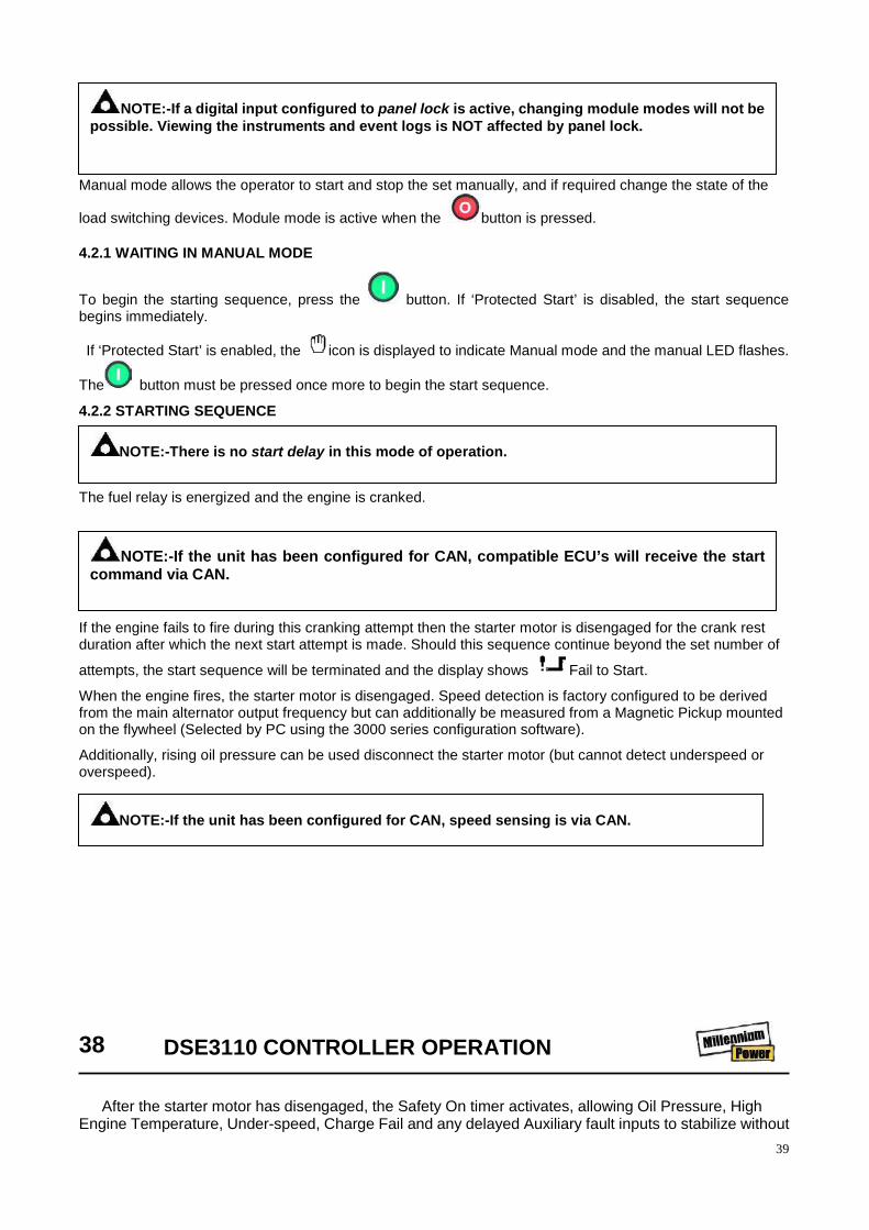
Manual mode allows the operator to start and stop the set manually, and if required change the state of the
load switching devices. Module mode is active when the button is pressed. 4.2.1 WAITING IN MANUAL MODE
To begin the starting sequence, press the button. If ‘Protected Start’ is disabled, the start sequence begins immediately.
If ‘Protected Start’ is enabled, the icon is displayed to indicate Manual mode and the manual LED flashes.
The button must be pressed once more to begin the start sequence.
4.2.2 STARTING SEQUENCE
The fuel relay is energized and the engine is cranked.
If the engine fails to fire during this cranking attempt then the starter motor is disengaged for the crank rest duration after which the next start attempt is made. Should this sequence continue beyond the set number of
attempts, the start sequence will be terminated and the display shows Fail to Start.
When the engine fires, the starter motor is disengaged. Speed detection is factory configured to be derived from the main alternator output frequency but can additionally be measured from a Magnetic Pickup mounted on the flywheel (Selected by PC using the 3000 series configuration software).
Additionally, rising oil pressure can be used disconnect the starter motor (but cannot detect underspeed or overspeed).
38 DSE3110 CONTROLLER OPERATION
After the starter motor has disengaged, the Safety On timer activates, allowing Oil Pressure, High
Engine Temperature, Under-speed, Charge Fail and any delayed Auxiliary fault inputs to stabilize without
NOTE:-If a digital input configured to panel lock is active, changing module modes will not be possible. Viewing the instruments and event logs is NOT affected by panel lock.
NOTE:-There is no start delay in this mode of operation.
NOTE:-If the unit has been configured for CAN, compatible ECU’s will receive the start command via CAN.
NOTE:-If the unit has been configured for CAN, speed sensing is via CAN.

40
triggering the fault. 4.2.3 ENGINE RUNNING
In manual mode, the load is not transferred to the generator unless a ‘loading request’ is made. A loading request can come from a number of sources. Activation of an auxiliary input that has been configured to remote start on load Activation of the inbuilt exercise scheduler if configured for ‘on load’ runs. Once the load has been transferred to the generator, it will not be automatically removed. To manually transfer the load back to the mains either:
• Press the auto mode button to return to automatic mode. The set will observe all auto mode start requests and stopping timers before beginning the Auto mode stopping sequence.
4.2.4 STOPPING SEQUENCE
In manual mode the set will continue to run until either:
The stop button is pressed – The set will immediately stop
The auto button is pressed. The set will observe all auto mode start requests and stopping timers before beginning the Auto mode stopping sequence.
4.3 FAULT ICONS
DSE3110 CONTROLLER OPERATION 39
ICON DESCRIPTION
AUXILIARY INPUTS Auxiliary inputs can be user configured and will display the message as written by the
user.
FAIL TO STOP The module has detected a condition that indicates that the engine is running when it
has been instructed to stop.
NOTE:-‘Fail to Stop’ could indicate a faulty oil pressure sensor -If engine is at rest check oil sensor wiring and configuration.
LOW OIL PRESSURE The module detects that the engine oil pressure has fallen below the low oil pressure
pre-alarm setting level after the Safety On timer has expired.
FAIL TO START The engine has not fired after the preset number of start attempts
NOTE:-The load transfer signal remains inactive until the Oil Pressure has risen. This prevents excessive wear on the engine.

41
40 FAULT FINDING
ICON DESCRIPTION
ENGINE HIGH TEMPERATURE
The module detects that the engine coolant temperature has exceeded the high engine temperature pre-alarm setting level after the Safety On timer has expired.
UNDERSPEED The engine speed has fallen below the underspeed pre alarm setting
OVERSPEED The engine speed has risen above the overspeed pre alarm setting
CHARGE FAILURE The auxiliary charge alternator voltage is low as measured from the W/L terminal.
LOW FUEL LEVEL The level detected by the fuel level sensor is below the low fuel level setting.
BATTERY UNDER VOLTAGE / BATTERY OVER VOLTAGE
The DC supply has fallen below or risen above the low/high volts setting level.
GENERATOR UNDER VOLTAGE
The generator output voltage has fallen below the pre-set pre-alarm setting after the Safety On timer has expired.
GENERATOR OVER VOLTAGE
The generator output voltage has risen above the pre-set pre-alarm setting.
GENERATOR UNDER FREQUENCY
The generator output frequency has fallen below the pre-set pre-alarm setting after the Safety On timer has expired.
GENERATOR OVER FREQUENCY
The generator output frequency has risen above the pre-set pre-alarm setting.
CAN ECU WARNING CAN ECU SHUTDOWN
The engine ECU has detected an alarm – CHECK ENGINE LIGHT Contact Engine Manufacturer for support.
CAN DATA FAIL The module is configured for CAN operation and does not detect data on the engine
Can datalink.
EMERGENCY STOP
The emergency stop button has been depressed. This is a failsafe (normally closed to battery positive) input and will immediately stop the set should the signal be removed. Removal of the battery positive supply from the emergency stop input will also remove DC supply from the Fuel and Start outputs of the controller.
NOTE:-The Emergency Stop Positive signal must be present otherwise the unit will shutdown.
MAGNETIC PICKUP FAILURE
Pulses are no longer being detected from the magnetic pickup probe (3110-xxx-01 magnetic pickup version only)
INTERNAL MEMORY ERROR
Either the configuration file or engine file memory is corrupted. Contact your supplier for assistance.
FAULT CAUSE REMEDY

42
FAULT FINDING 41
Engine fails to start.
Low battery charge. Check the fan belt tension, battery and cable connections. Bad earth connection.
Check the earth cables, clean as required.
Loose connection.
Locate and make the connection good.
Fuel starvation.
Check the fuel level and fuel system components. Replace the fuel filter if necessary.
Relay failed. Replace the relay.
Engine starts but stalls when the switch returns to position I.
Electrical fault Test the electrical circuits. Low engine oil pressure. Check the oil level and the oil filter(s). Faulty relay
Check the relays.
Faulty key-switch Check the key-switch.
Engine starts but will not run or engine shuts down prematurely.
Electrical fault. Test the electrical circuits Low engine oil pressure. Check the oil level and oil filter(s).
Safety shut-down system in operation.
Check the safety shut-down switches
Fuel starvation. Check the fuel level and fuel system components. Replace the fuel filter if necessary.
Switch failure Test the switches.
Water present in fuel system. Check the water separator and clean if required.
Faulty relay. Check the relay in the holder and replace if necessary.
Engine Overheats.
Reduced cooling air from fan. Check the fan and the drive belts. Check for any obstruction inside the cowl.
Engine speed too high.
Incorrect throttle arm setting. Check the engine speed setting.
FAULT CAUSE REMEDY
Engine speed too low.
Incorrect throttle arm setting. Check the throttle setting.
Blocked fuel filter. Check and replace if necessary
Blocked air filter. Check and replace the element if necessary.
Excessive vibration. Engine speed too low. See “Engine speed too low”
FAULT CAUSE REMEDY

43
The mast does not rise.
Pump does not operate. Battery is not connected/charged. Key switch is not in “ON” position. Emergency stop button is pushed in.
Pump operates but mast does not rise.
Hydraulic oil level is too low. The hydraulic hose is defective or leaking. Lowering valve has failed in open position. Suction tube in the tank is defective.
Mast rise but not completely. A pulley mounting pin is defective or missing. Cable assembly is damaged. Hydraulic oil level is too low.
FAULT CAUSE REMEDY The mast lowers on its own.
The mast has lowered when the operator returns to the machine.
The hydraulic hose is defective or leaking.
The mast does not lower.
Hydraulic cylinder does not lower.
Key switch is not in “ON” position. Emergency stop button is pushed in. The hydraulic hose is defective. Mast is jammed or damaged in raised position. The mast is raised while machine not leveled properly. The hose burst valve in cylinder is damaged or blocked. Damaged sliding pads stop the mast from coming down.
Mast falls down.
Mast falls down suddenly and very fast.
Cable failed. Pulley failed.