mpls configuration
TRANSCRIPT

8/11/2019 MPLS Configuration
http://slidepdf.com/reader/full/mpls-configuration 1/98
Corporate Headquarters
Cisco Systems, Inc.170 West Tasman DriveSan Jose, CA 95134-1706USAhttp://www.cisco.comTel: 408 526-4000
800 553-NETS (6387)Fax: 408 526-4100
Cisco IOS-XR MPLS Configuration Guide
Cisco IOS-XR Software Release 2.0
Text Part Number: OL-5553-01

8/11/2019 MPLS Configuration
http://slidepdf.com/reader/full/mpls-configuration 2/98
THE SPECIFICATIONS AND INFORMATION REGARDING THE PRODUCTS IN THIS MANUAL ARE SUBJECT TO CHANGE WITHOUT NOTICE. ALL
STATEMENTS, INFORMATION, AND RECOMMENDATIONS IN THIS MANUAL ARE BELIEVED TO BE ACCURATE BUT ARE PRESENTED WITHOUT
WARRANTY OF ANY KIND, EXPRESS OR IMPLIED. USERS MUST TAKE FULL RESPONSIBILITY FOR THEIR APPLICATION OF ANY PRODUCTS.
THE SOFTWARE LICENSE AND LIMITED WARRANTY FOR THE ACCOMPANYING PRODUCT ARE SET FORTH IN THE INFORMATION PACKET THAT
SHIPPED WITH THE PRODUCT AND ARE INCORPORATED HEREIN BY THIS REFERENCE. IF YOU ARE UNA BLE TO LOCATE THE SOFTWARE LICENSEOR LIMITED WARRANTY, CONTACT YOUR CISCO REPRESENTATIVE FOR A COPY.
The Cisco implementation of TCP header compression is an adaptation of a program developed by the University of California, Berkeley (U CB) as part of UCB’s public
domain version of the UNIX operating system. All rights reserved. Copyright © 1981, Regents of the University of California.
NOTWITHSTANDING ANY OTHER WARRANTY HEREIN, ALL DOCUMENT FILES AND SOFTWARE OF THESE SUPPLIERS ARE PROVIDED “AS IS” WITH
ALL FAULTS. CISCO AND THE ABOVE-NAMED SUPPLIERS DISCLAIM ALL WARRANTIES, EXPRESSED OR IMPLIED, INCLUDING, WITHOUT
LIMITATION, THOSE OF MERCHANTABILITY, FITNESS FOR A PARTICULAR PURPOSE AND NONINFRINGEMENT OR ARISING FROM A COURSE OF
DEALING, USAGE, OR TRADE PRACTICE.
IN NO EVENT SHALL CISCO OR ITS SUPPLIERS BE LIABLE FOR ANY IND IRECT, SPECIAL, CONSEQUENTIAL, OR INCIDENTAL DAMAGES, INCLUDING,
WITHOUT LIMITATION, LOST PROFITS OR LOSS OR DAMAGE TO DATA ARISING OUT OF THE USE OR INABILITY TO USE THIS MANUAL, EVEN IF CISCO
OR ITS SUPPLIERS HAVE BEEN ADVISED OF THE POSSIBILITY OF SUCH DAMAG ES.
Cisco IOS-XR MPLS Configuration Guide
Copyright © 2004 Cisco Systems, Inc. All rights reserved.
CCIP, CCSP, the Cisco Arrow logo, the Cisco Powered Network mark, Cisco Unity, Follow Me Browsing, FormShare, and StackWise are trademarks of Cisco Systems, Inc.;
Changing the Way We Work, Live, Play, and Learn, and iQuick Study are service marks of Cisco Systems, Inc.; and Aironet, ASIST, BPX, Catalyst, CCDA, CCDP, CCIE, CCNA,
CCNP, Cisco, the Cisco Certified Internetwork Expert logo, Cisco IOS, the Cisco IOS logo, Cisco Press, Cisco Systems, Cisco Systems Capital, the Cisco Systems logo,
Empowering the Internet Generation, Enterprise/Solver, EtherChannel, EtherFast, EtherSwitch, Fast Step, GigaDrive, GigaStack, HomeLink, Internet Quotient, IOS, IP/TV, iQ
Expertise, the iQ logo, iQ Net Readiness Scorecard, LightStream, Linksys, MeetingPlace, MGX, the Networkers logo, Networking Academy, Network Registrar, Packet , PIX,
Post-Routing, Pre-Routing, ProConnect, RateMUX, Registrar, ScriptShare, SlideCast, SMARTnet, StrataView Plus, SwitchProbe, TeleRouter, The Fastest Way to Increase Your
Internet Quotient, TransPath, and VCO are registered trademarks of Cisco Systems, Inc. and/or its affiliates in the United States and certain other countries.
All other trademarks mentioned in this document or Website are the property of their respective owners. The use of the word partner does not imply a partnership relationship
between Cisco and any other company. (0403R)

8/11/2019 MPLS Configuration
http://slidepdf.com/reader/full/mpls-configuration 3/98
iii
Cisco IOS-XR MPLS Configuration Guide
C O N T E N T S
Implementing MPLS Label Distribution Protocol on Cisco IOS-XR Software MPC-1
Contents MPC-1
Prerequisites for Implementing Cisco MPLS LDP MPC-2
Information About Implementing Cisco MPLS LDP MPC-2
Comparison Between Cisco IOS and Cisco IOS-XR MPC-2
Overview of Label Distribution Protocol MPC-2
Label Switched Paths MPC-2
LDP Control Plane MPC-3
Exchanging Label Bindings MPC-4
Setting Up LDP Forwarding MPC-5
LDP Graceful Restart MPC-6
Control Plane Failure MPC-6
Phases in Graceful Restart MPC-8
How to Implement LDP on Cisco IOS-XR Software MPC-10
Configuring LDP Discovery Parameters MPC-10
Configuring LDP Discovery Over a Link MPC-12
Prerequisites MPC-12
Configuring LDP Discovery for Active Targeted Hellos MPC-14
Prerequisites MPC-14
Configuring LDP Discovery for Passive Targeted Hellos MPC-15
Prerequisites MPC-15
Setting Up LDP Neighbors MPC-17
Prerequisites MPC-17
Setting Up LDP Forwarding MPC-19
Prerequisites MPC-19
Setting Up LDP NSF Using Graceful Restart MPC-21
Prerequisites MPC-21
Configuration Examples for Implementing LDP MPC-24Configuring LDP with Graceful Restart: Example MPC-24
Configuring LDP Discovery: Example MPC-24
Configuring LDP Link: Example MPC-24
Configuring LDP Discovery for Targeted Hellos: Example MPC-25
Configuring for LDP Neighbors: Example MPC-25
Configuring MPLS LDP Forwarding: Example MPC-25
Configuring LDP Non-Stop Forwarding with Graceful Restart: Example MPC-25

8/11/2019 MPLS Configuration
http://slidepdf.com/reader/full/mpls-configuration 4/98
Contents
iv
Cisco IOS-XR MPLS Configuration Guide
Where to Go Next MPC-26
Additional References MPC-26
Related Documents MPC-26
Standards MPC-26
MIBs MPC-27
RFCs MPC-27
Technical Assistance MPC-27
Glossary MPC-28
Implementing MPLS Traffic Engineering on Cisco IOS-XR Software MPC-31
Contents MPC-31
Prerequisites for Implementing Cisco MPLS Traffic Engineering MPC-32
Information About Implementing MPLS Traffic Engineering MPC-32
Comparison of Cisco IOS MPLS-TE and Cisco IOS-XR MPLS-TE MPC-32
Overview of MPLS Traffic Engineering MPC-33
Benefits of MPLS Traffic Engineering MPC-33
How MPLS Traffic Engineering Works MPC-33
Protocol-Based CLI MPC-34
Differentiated Services Traffic Engineering MPC-34
Flooding MPC-34
Flooding Triggers MPC-35
Flooding Thresholds MPC-35
Fast Reroute MPC-35
How to Implement Traffic Engineering on Cisco IOS-XR MPC-36
Building MPLS-TE Topology MPC-36
Prerequisites MPC-36
Creating an MPLS-TE Tunnel MPC-39
Prerequisites MPC-39
Forwarding over the MPLS-TE Tunnel MPC-42
Prerequisites MPC-42
Protecting the MPLS Tunnel with Fast Reroute MPC-44
Prerequisites MPC-44
Restrictions MPC-44
Creating a Diff-Serv (Differentiated Services) TE Tunnel MPC-46
Prerequisites MPC-46
Configuration Examples for Cisco MPLS Traffic Engineering MPC-48
Configuring Fast Reroute and SONET APS: Example MPC-48
Building MPLS-TE Topology and Tunnels: Example MPC-49
Additional References MPC-50

8/11/2019 MPLS Configuration
http://slidepdf.com/reader/full/mpls-configuration 5/98
Contents
v
Cisco IOS-XR MPLS Configuration Guide
Related Documents MPC-50
Standards MPC-50
MIBs MPC-50
RFCs MPC-50
Technical Assistance MPC-51
Glossary MPC-52
Implementing MPLS Forwarding on Cisco IOS-XR Software MPC-55
Comparison of Cisco IOS MPLS Forwarding and Cisco IOS-XR MPLS Forwarding MPC-55
MFI Control Plane Services MPC-55
MFI Data Plane Services MPC-55
Implementing RSVP for MPLS-TE and MPLS O-UNI on Cisco IOS-XR Software MPC-57
Contents MPC-57
Prerequisites for Implementing RSVP for MPLS-TE and MPLS O-UNI MPC-58
Information About Implementing RSVP for MPLS-TE and MPLS O-UNI MPC-58
Comparison of Cisco IOS RSVP and Cisco IOS-XR RSVP MPC-58
Overview of RSVP for MPLS-TE and MPLS O-UNI MPC-58
LSP Setup MPC-59
High Availability MPC-60
Graceful Restart MPC-60
Differential Service Tunnels MPC-62
How to Implement RSVP on Cisco IOS-XR MPC-62
Configuring Traffic Engineering Tunnel Bandwidth MPC-62
Confirming DiffServ TE Bandwidth MPC-63
Configuring MPLS O-UNI Bandwidth MPC-65
Enabling Graceful Restart MPC-65
Verifying RSVP Configuration MPC-66
Configuration Examples for RSVP MPC-69
Bandwidth Configuration: Example MPC-69
Refresh Reduction and Reliable Messaging Configuration: Example MPC-69
Changing the Refresh Interval and the Number of Refresh Messages MPC-69
Configuring Retransmit Time Used in Reliable Messaging MPC-70Configuring Acknowledgement Times MPC-70
Changing the Summary Refresh Message Size MPC-70
Disabling Refresh Reduction MPC-70
Configuring Graceful Restart: Example MPC-70
Enabling the Graceful Restart Feature MPC-70
Changing the Restart-Time MPC-71
Changing the Hello Interval MPC-71

8/11/2019 MPLS Configuration
http://slidepdf.com/reader/full/mpls-configuration 6/98
Contents
vi
Cisco IOS-XR MPLS Configuration Guide
Setting DSCP for RSVP Packets: Example MPC-71
Additional References MPC-71
Related Documents MPC-71
Standards MPC-72
MIBs MPC-72
RFCs MPC-72
Technical Assistance MPC-72
Glossary MPC-73
Implementing MPLS Optical User Network Interface Protocol on Cisco IOS-XR Software MPC-75
Contents MPC-75
Prerequisites for Implementing Cisco MPLS O-UNI MPC-76
Information About Implementing Cisco MPLS O-UNI MPC-76
Comparison of Cisco IOS O-UNI and Cisco IOS-XR O-UNI MPC-76
O-UNI Overview MPC-77
How to Implement O-UNI on Cisco Cisco IOS-XR MPC-78
Setting Up an O-UNI Connection MPC-79
Prerequisites MPC-79
Tearing Down an O-UNI Connection MPC-82
Verifying MPLS O-UNI Configuration MPC-84
Configuration Examples for MPLS O-UNI MPC-87
O-UNI Neighbor and Data Link Configuration: Examples MPC-87
O-UNI Router ID ConfigurationMPC-87
O-UNI-N Neighbor Configuration MPC-87
O-UNI Data Link Configuration MPC-87
O-UNI Connection Establishment: Example MPC-88
O-UNI Connection Configuration at Active Side MPC-88
O-UNI Connection Configuration at Passive Side MPC-88
O-UNI Connection Tear-Down: Example MPC-88
O-UNI Connection Deletion at Active Side MPC-88
O-UNI Connection Deletion at Passive Side MPC-88
Additional References MPC-89
Related Documents MPC-89
Standards MPC-89
MIBs MPC-89
RFCs MPC-90
Technical Assistance MPC-90
Glossary MPC-91

8/11/2019 MPLS Configuration
http://slidepdf.com/reader/full/mpls-configuration 7/98
Corporate Headquarters:
Copyright © 2004 Cisco Systems, Inc. All rights reserved.
Cisco Systems, Inc., 170 West Tasman Drive, San Jose, CA 95134-1706 USA
Implementing MPLS Label Distribution Protocolon Cisco IOS-XR Software
Multiprotocol Label Switching (MPLS) is a standards-based solution driven by the Internet Engineering
Task Force (IETF) that was devised to convert the Internet and IP backbones from best-effort networks
into business-class transport mediums.
MPLS, with its label switching capabilities, eliminates the need for an IP route look-up and creates a
virtual circuit (VC) switching function, allowing enterprises the same performance on their IP-based
network services as with those delivered over traditional networks such as Frame Relay or ATM.
Label Distribution Protocol (LDP) is a protocol that performs label distribution in MPLS environments.
LDP performs hop-by-hop or dynamic path setup; it does not provide end-to-end switching services.
LDP assigns labels to routes using the underlying Interior Gateway Protocols (IGP) routing protocols.
LDP can also provide constraint-based routing using LDP extensions for traffic engineering.
LDP is deployed in the core of the network and is one of the key protocols used in MPLS-based layer 2
and 3 Virtual Private Networks (VPNs).
Feature History for the Cisco MPLS LDP Feature
Contents Prerequisites for Implementing Cisco MPLS LDP, page MPC-2
• Information About Implementing Cisco MPLS LDP, page MPC-2
• How to Implement LDP on Cisco IOS-XR Software, page MPC-10
• Configuration Examples for Implementing LDP, page MPC-24
• Where to Go Next, page MPC-26
• Additional References, page MPC-26
• Glossary, page MPC-28
Feature History
Release Modification
Release 2.0 This feature was introduced.

8/11/2019 MPLS Configuration
http://slidepdf.com/reader/full/mpls-configuration 8/98
Implementing MPLS Label Distribution Protocol on Cisco IOS-XR Software
Prerequisites for Implementing Cisco MPLS LDP
MPC-2
Cisco IOS-XR MPLS Configuration Guide
Prerequisites for Implementing Cisco MPLS LDPThe following are required to implement MPLS LDP on the router:
• Cisco CRS-1 Series router.
• An installed composite mini-image and the MPLS package.• IGP activated on the router.
• The task ID mpls-ldp, which provides the user with these task privileges:
– The read privilege for show and debug commands.
– The read and write privileges for any action commands (such as clear, show, or test)
Information About Implementing Cisco MPLS LDPTo implement MPLS LDP you must understand the following concepts:
• Comparison Between Cisco IOS and Cisco IOS-XR, page MPC-2• Overview of Label Distribution Protocol, page MPC-2
• LDP Graceful Restart, page MPC-6
Comparison Between Cisco IOS and Cisco IOS-XR
• Protocol-based command-line interface (CLI), as implemented in both Cisco IOS software and
Cisco IOS-XR software.
• New configuration modes in Cisco IOS-XR software.
• Task IDs are implemented for a new level of system control.
• Router IDs are configured globally, unless they are overridden using the mpls ldp router-id
command.
• New show commands to facilitate Cisco IOS-XR software operation.
Overview of Label Distribution Protocol
LDP performs label distribution in MPLS environments. LDP uses hop-by-hop or dynamic path setup,
but does not provide end-to-end switching services. Labels are assigned to routes that are chosen by the
underlying IGP routing protocols. The Label Switched Paths (LSPs) that result from the routes forward
labeled traffic across the MPLS backbone to adjacent nodes.
Label Switched Paths
LSPs are created in the network by enabling MPLS. They can be created statically, by RSVP traffic
engineering (TE) or by LDP. LSPs created by LDP perform hop-by-hop path setup instead of an
end-to-end path.

8/11/2019 MPLS Configuration
http://slidepdf.com/reader/full/mpls-configuration 9/98
Implementing MPLS Label Distribution Protocol on Cisco IOS-XR Software
Information About Implementing Cisco MPLS LDP
MPC-3
Cisco IOS-XR MPLS Configuration Guide
LDP Control Plane
The control plane enables label switched routers (LSRs) to discover their potential peer routers and then
to establish LDP sessions with those peers to exchange label binding information. Figure 1 shows the
control messages exchanged between LDP peers.
Figure 1 LDP Control Protocol
LDP uses the hello discovery mechanism to discover its neighbor/peer on the network. When LDP is
enabled on an interface, it sends hello messages to a link-local multicast address, and joins a specific
Multicast group to receive hellos from any other LSR present on the given link. When LSRs on a given
link receive hellos, they discover their neighbors and LDP session (using TCP) is established. hellos are
not only used to discover and trigger LDP sessions, but are also required to maintain LDP sessions. If acertain number of hellos from a given peer are missed in sequence, LDP sessions are brought down, until
the peer is discovered again.
LDP also supports non-link neighbors that could be multiple hops away on the network, using the
targeted hello mechanism. In these cases, hellos are sent on a directed, unicast address.
The first message in the session establishment phase is the initialization message, which is used to
negotiate session parameters. After session establishment, LDP sends a list of all its interface addresses
to its peers in an address message. Whenever a new address becomes available or unavailable, the peers
are notified regarding such changes via ADDRESS or ADDRESS_WITHDRAW messages respectively.
When MPLS LDP learns an IGP prefix, it allocates a label locally as the inbound label. The local binding
between the prefix label is conveyed to its peers via LABEL_MAPPING message. If the binding breaks
(the prefix becomes unavailable), then a LABEL_WITHDRAW message is sent to all its peers, which
then respond with a LABEL_RELEASE message.
The local label binding and remote label binding received from its peer(s) is used to setup forwarding
entries. Using routing information from the IGP protocol using the forwarding information base (FIB),
the next active hop is selected, and label binding learned from the next hop peer is used as the outbound
label while setting up the forwarding plane.
The LDP session is also kept alive using the LDP keepalive mechanism, where an LSR sends a keepalive
message periodically to its peers. If no messages are received and a certain number of keepalive
messages are missed from a peer, the session is declared dead, and brought down immediately.
9 5 1 3 0
R1HELLO
R2
R3
INITADDRESS, ADDRES_WITHDRAWLABEL_MAPPING, LABEL_WITHDRAW,LABEL_RELEASEKEEP_ALIVE
R4
8/11/2019 MPLS Configuration
http://slidepdf.com/reader/full/mpls-configuration 10/98
Implementing MPLS Label Distribution Protocol on Cisco IOS-XR Software
Information About Implementing Cisco MPLS LDP
MPC-4
Cisco IOS-XR MPLS Configuration Guide
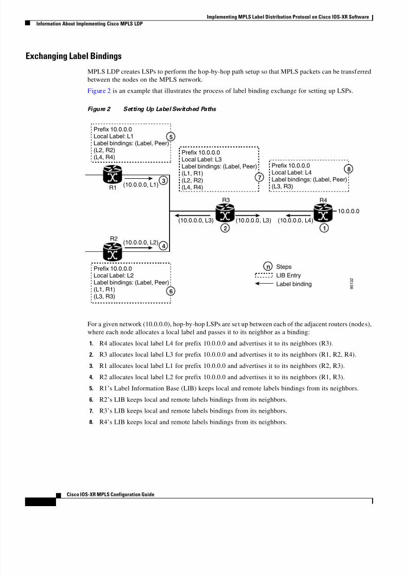
Exchanging Label Bindings
MPLS LDP creates LSPs to perform the hop-by-hop path setup so that MPLS packets can be transferred
between the nodes on the MPLS network.
Figure 2 is an example that illustrates the process of label binding exchange for setting up LSPs.
Figure 2 Setting Up Label Switched Paths
For a given network (10.0.0.0), hop-by-hop LSPs are set up between each of the adjacent routers (nodes),
where each node allocates a local label and passes it to its neighbor as a binding:
1. R4 allocates local label L4 for prefix 10.0.0.0 and advertises it to its neighbors (R3).
2. R3 allocates local label L3 for prefix 10.0.0.0 and advertises it to its neighbors (R1, R2, R4).
3. R1 allocates local label L1 for prefix 10.0.0.0 and advertises it to its neighbors (R2, R3).
4. R2 allocates local label L2 for prefix 10.0.0.0 and advertises it to its neighbors (R1, R3).
5. R1’s Label Information Base (LIB) keeps local and remote labels bindings from its neighbors.
6. R2’s LIB keeps local and remote labels bindings from its neighbors.
7. R3’s LIB keeps local and remote labels bindings from its neighbors.
8. R4’s LIB keeps local and remote labels bindings from its neighbors.
9 5 1 3 2
R1
R2
R3
(10.0.0.0, L3)
(10.0.0.0, L1)
(10.0.0.0, L2)
(10.0.0.0, L3) (10.0.0.0, L4)
10.0.0.0R4
n
12
4
3
Prefix 10.0.0.0Local Label: L3Label bindings: (Label, Peer)(L1, R1)(L2, R2)(L4, R4)
Prefix 10.0.0.0Local Label: L1Label bindings: (Label, Peer)(L2, R2)(L4, R4)
Prefix 10.0.0.0Local Label: L2Label bindings: (Label, Peer)(L1, R1)(L3, R3)
Prefix 10.0.0.0Local Label: L4Label bindings: (Label, Peer)(L3, R3)
Steps
LIB Entry
Label binding
5
7
8
6

8/11/2019 MPLS Configuration
http://slidepdf.com/reader/full/mpls-configuration 11/98
Implementing MPLS Label Distribution Protocol on Cisco IOS-XR Software
Information About Implementing Cisco MPLS LDP
MPC-5
Cisco IOS-XR MPLS Configuration Guide
Setting Up LDP Forwarding
Once label bindings are learned, the MPLS LDP control plane is ready to setup the MPLS forwarding
plane as shown in Figure 3.
Figure 3 Forwarding Setup
1. Because R3 is next hop for 10.0.0.0 as notified by the forwarding information base (FIB), R1 selectslabel binding from R3 and installs forwarding entry (L1, L3).
2. Because R3 is next hop for 10.0.0.0 (as notified by FIB), R2 selects label binding from R3 and
installs forwarding entry (L2, L3).
3. Because R4 is next hop for 10.0.0.0 (as notified by FIB), R3 selects label binding from R4 and
installs forwarding entry (L3, L4).
4. Because next hop for 10.0.0.0 (as notified by FIB) is beyond R4, R4 uses NO-LABEL as the
outbound and installs the forwarding entry (L4); the outbound packet will be forwarded IP-only.
5. Incoming IP traffic on ingress LSR R1 gets label-imposed and is forwarded as an MPLS packet with
label L3.
6. Incoming IP traffic on ingress LSR R2 gets label-imposed and is forwarded as an MPLS packet with
label L3.
7. R3 receives an MPLS packet with label L3, looks up in the MPLS label forwarding table and
switches this packet as an MPLS packet with label L4.
8. R4 receives an MPLS packet with label L4, looks up in the MPLS label forwarding table and finds
that it should go Unlabeled, pops the top label, and passes it to the IP forwarding plane.
9. IP forwarding takes over and forwards the packet onward.
9 5 1 2 8
Prefix10.0.0.0
In LabelL1
Out LabelL3
L3
R1
R2
R3
Packet in-transit
R4
n
Prefix10.0.0.0
In LabelL3
Out LabelL4
Steps
Forwarding Entry
LSP
Packet
Prefix10.0.0.0
In LabelL4
Out LabelUnlabelled
Prefix10.0.0.0
In LabelL2
Out LabelL3
IPL3 IP
L3 IP
L4 IP
IP
IPIP
1
3
7 8 9
2
5
6
4

8/11/2019 MPLS Configuration
http://slidepdf.com/reader/full/mpls-configuration 12/98
Implementing MPLS Label Distribution Protocol on Cisco IOS-XR Software
Information About Implementing Cisco MPLS LDP
MPC-6
Cisco IOS-XR MPLS Configuration Guide
LDP Graceful Restart
MPLS LDP graceful restart (GR), provides a control plane mechanism to ensure high availability, allows
detection and recovery from failure conditions while preserving Non-Stop Forwarding (NSF) services.
Graceful restart is a way to recover from signaling and control plane failures without impacting
forwarding.Without LDP graceful restart, when an established session fails, the corresponding forwarding states are
cleaned immediately from the restarting and peer nodes. In this case LDP forwarding will have to restart
from the beginning, causing a potential loss of data and connectivity.
The LDP graceful restart capability is negotiated between two peers during session initialization time,
in FT SESSION TLV. In this typed length value (TLV), each peer advertises the following information
to its peers:
• Reconnect time: the maximum time that other peer should wait for this LSR to reconnect after
control channel failure.
• Recovery time: Max time that other peer has on its side to reinstate or refresh its states with this
LSR. This time is used only during session reestablishment after earlier session failure.
• FT flag: This flag indicates whether a restart could restore the preserved (local) node state.
Once the graceful restart session parameters are conveyed and session is up and running, GR procedures
are activated.
Control Plane Failure
When a control plane failure occurs, connectivity can be affected. The forwarding states installed by the
router control planes are lost, and the in-transit packets could be dropped, thus breaking NSF.
Figure 4 illustrates a control plane failure and shows the process and results of a control plane failure
leading to loss of connectivity.

8/11/2019 MPLS Configuration
http://slidepdf.com/reader/full/mpls-configuration 13/98
Implementing MPLS Label Distribution Protocol on Cisco IOS-XR Software
Information About Implementing Cisco MPLS LDP
MPC-7
Cisco IOS-XR MPLS Configuration Guide
Figure 4 Control Plane Failure
1. The R4 LSR control plane restarts.2. LIB is lost when the control plane restarts.
3. The forwarding states installed by the R4 LDP control plane are immediately deleted.
4. Any in-transit packets flowing from R3 to R4 (still labelled with L4) arrive at R4.
5. The MPLS forwarding plane at R4 performs a lookup on local label L4 which fails. Because of this
failure, the packet is dropped and NSF is not met.
6. The R3 LDP peer detects the failure of the control plane channel and then deletes its label bindings
from R4.
7. The R3 control plane stops using outgoing labels from R4 and deletes the corresponding forwarding
state (rewrites), which in turn causes forwarding disruption.
8. The established LSPs connected to R4 are terminated at R3, resulting in broken end-to-end LSPsfrom R1 to R4.
9. The established LSPs connected to R4 are terminated at R3, resulting in broken LSPs end-to-end
from R2 to R4.
9 5 1 2 7
Prefix10.0.0.0
In LabelL1
Out LabelL3
L3
R1
R2
R3
Packet in-transit
R4
6
9
2
37
8
n
1
5
4
Prefix10.0.0.0
In LabelL3
Out LabelL4
Prefix 10.0.0.0Local Label: L3Label bindings: (Label, Peer)
(L1, R1)(L2, R2)(L4, R4)
Prefix 10.0.0.0Local Label: L3Label bindings: (Label, Peer)(L3, R3)
Steps
Forwarding Entry
LSP
Packet
Prefix10.0.0.0
In LabelL4
Out LabelUnlabelled
Prefix10.0.0.0
In LabelL2
Out LabelL3
IP L4 IP
Drop
bucket

8/11/2019 MPLS Configuration
http://slidepdf.com/reader/full/mpls-configuration 14/98
Implementing MPLS Label Distribution Protocol on Cisco IOS-XR Software
Information About Implementing Cisco MPLS LDP
MPC-8
Cisco IOS-XR MPLS Configuration Guide
Phases in Graceful Restart
The graceful restart mechanism can be divided into different phases as follows:
• Control communication failure detection
• Forwarding state maintenance during failure
• Control state recovery
Control Communication Failure Detection
Control communication failure is detected when the system detects either:
• Missed LDP hello discovery messages
• Missed LDP keepalive protocol messages
• Detection of Transmission Control Protocol (TCP) disconnection a with a peer
Forwarding State Maintenance During Failure
Persistent forwarding states at each LSR are achieved through persistent storage (checkpoint) by theLDP control plane. While the control plane is in the process of recovering, the forwarding plane keeps
the forwarding states, but marks them as stale. Similarly, the peer control plane also keeps (and marks
as stale) the installed forwarding rewrites associated with the node that is restarting. The combination of
local node forwarding and remote node forwarding plane states ensures NSF and no disruption in the
traffic.
Control State Recovery
Recovery occurs when the session is reestablished and label bindings are exchanged again. This process
allows the peer nodes to synchronize and to refresh stale forwarding states.
Recovery with Graceful-Restart
Figure 5 illustrates the process of failure recovery using graceful restart.

8/11/2019 MPLS Configuration
http://slidepdf.com/reader/full/mpls-configuration 15/98
Implementing MPLS Label Distribution Protocol on Cisco IOS-XR Software
Information About Implementing Cisco MPLS LDP
MPC-9
Cisco IOS-XR MPLS Configuration Guide
Figure 5 Recovering with Graceful-Restart
1. The router R4 LSR control plane restarts.
2. With the control plane restart, LIB is gone but forwarding states installed by R4’s LDP control plane
are not immediately deleted but are marked as stale.
3. Any in-transit packets from R3 to R4 (still labelled with L4) arrive at R4.
4. The MPLS forwarding plane at R4 performs a successful lookup for the local label L4 as forwarding
is still intact. The packet is then forwarded accordingly.
5. The router R3 LDP peer detects the failure of the control plane and channel and deletes the label
bindings from R4. The peer, however, does not delete the corresponding forwarding states but marks
them as stale.
6. At this point there are no forwarding disruptions.
7. The peer also starts the neighbor reconnect timer using the reconnect time value.
8. The established LSPs going toward the router R4 are still intact, and there are no broken LSPs.
When the LDP control plane recovers, the restarting LSR starts its forwarding state hold timer and
restores its forwarding state from the checkpointed data. This action reinstates the forwarding state and
entries and marks them as not stale.
The restarting LSR then reconnects to its peer, indicating in the FT Session TLV, that it either was or was
not able to restore its state successfully. If it was able to restore the state, then the bindings are
resynchronized.
9 5 1 2 6
Prefix10.0.0.0
In LabelL1
Out LabelL3
L3
R1
R2
R3
Packet in-transit
R4
5 2
n
1
43
Prefix10.0.0.0
In LabelL3
Out LabelL4
Prefix 10.0.0.0Local Label: L3Label bindings: (Label, Peer)
(L1, R1)(L2, R2)(L4, R4)
Prefix 10.0.0.0
Local Label: L3Label bindings: (Label, Peer)(L3, R3)
Steps
Forwarding Entry
LSP
Packet
Prefix10.0.0.0
In LabelL4
Out LabelUnlabelled
Prefix10.0.0.0
In LabelL2
Out LabelL3
IP L4 IP IP

8/11/2019 MPLS Configuration
http://slidepdf.com/reader/full/mpls-configuration 16/98
Implementing MPLS Label Distribution Protocol on Cisco IOS-XR Software
How to Implement LDP on Cisco IOS-XR Software
MPC-10
Cisco IOS-XR MPLS Configuration Guide
The peer LSR stops the neighbor reconnect timer (started by the restarting LSR), when the restarting
peer connects and starts the neighbor recovery timer. The peer LSR checks the FT Session TLV if the
restarting peer was able to restore its state successfully. It then reinstates the corresponding forwarding
state entries and receives binding from the restarting peer. When the recovery timer expires, any
forwarding state that is still marked as stale is deleted.
If the restarting LSR fails to recover (restart), the restarting LSR forwarding state and entries willeventually timeout and will be deleted, while neighbor-related forwarding states or entries are removed
by the Peer LSR on expiration of the reconnect or recovery timers.
How to Implement LDP on Cisco IOS-XR SoftwareA typical MPLS LDP deployment requires coordination among several global neighbor routers. There
are various configuration tasks that are required to implement MPLS LDP on Cisco IOS-XR. These tasks
include configuration of LDP discovery parameters, link discovery, discovery using targeted hello
messages, LDP neighbors, MPLS forwarding, and graceful restart.
This section contains the following procedures:
• Configuring LDP Discovery Parameters, page MPC-10
• Configuring LDP Discovery Over a Link, page MPC-12
• Configuring LDP Discovery for Active Targeted Hellos, page MPC-14
• Setting Up LDP Neighbors, page MPC-17
• Setting Up LDP Forwarding, page MPC-19
• Setting Up LDP NSF Using Graceful Restart, page MPC-21
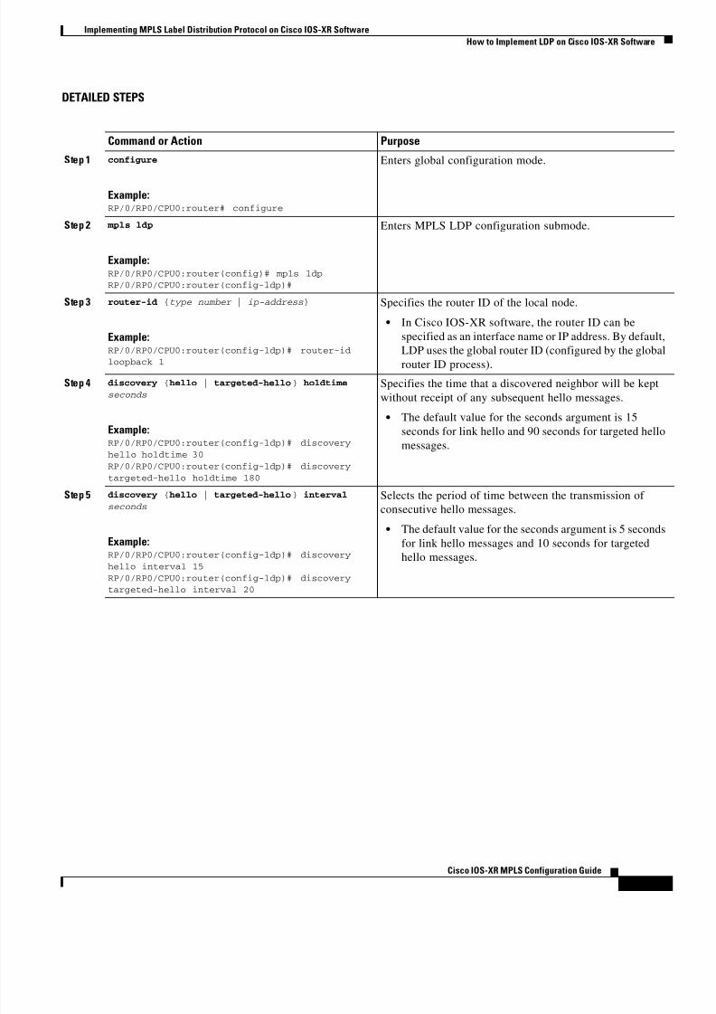
Configuring LDP Discovery Parameters
Perform this task to configure LDP discovery parameters, which may be crucial for LDP operations. TheLDP discovery mechanism is used to discover/locate neighbor nodes.
SUMMARY STEPS
1. configure
2. mpls ldp
3. router-id {type number | ip-address}
4. discovery {hello | targeted-hello} holdtime seconds
5. discovery {hello | targeted-hello} interval seconds
6. end or commit
7. show mpls ldp parameters
8/11/2019 MPLS Configuration
http://slidepdf.com/reader/full/mpls-configuration 17/98
Implementing MPLS Label Distribution Protocol on Cisco IOS-XR Software
How to Implement LDP on Cisco IOS-XR Software
MPC-11
Cisco IOS-XR MPLS Configuration Guide
DETAILED STEPS
Command or Action Purpose
Step 1 configure
Example:RP/0/RP0/CPU0:router# configure
Enters global configuration mode.
Step 2 mpls ldp
Example:RP/0/RP0/CPU0:router(config)# mpls ldpRP/0/RP0/CPU0:router(config-ldp)#
Enters MPLS LDP configuration submode.
Step 3 router-id {type number | ip-address}
Example:
RP/0/RP0/CPU0:router(config-ldp)# router-idloopback 1
Specifies the router ID of the local node.
• In Cisco IOS-XR software, the router ID can be
specified as an interface name or IP address. By default,
LDP uses the global router ID (configured by the globalrouter ID process).
Step 4 discovery {hello | targeted-hello} holdtime
seconds
Example:RP/0/RP0/CPU0:router(config-ldp)# discovery
hello holdtime 30
RP/0/RP0/CPU0:router(config-ldp)# discovery
targeted-hello holdtime 180
Specifies the time that a discovered neighbor will be kept
without receipt of any subsequent hello messages.
• The default value for the seconds argument is 15
seconds for link hello and 90 seconds for targeted hello
messages.
Step 5 discovery {hello | targeted-hello} interval
seconds
Example:RP/0/RP0/CPU0:router(config-ldp)# discovery
hello interval 15
RP/0/RP0/CPU0:router(config-ldp)# discoverytargeted-hello interval 20
Selects the period of time between the transmission of
consecutive hello messages.
• The default value for the seconds argument is 5 secondsfor link hello messages and 10 seconds for targeted
hello messages.
8/11/2019 MPLS Configuration
http://slidepdf.com/reader/full/mpls-configuration 18/98
Implementing MPLS Label Distribution Protocol on Cisco IOS-XR Software
How to Implement LDP on Cisco IOS-XR Software
MPC-12
Cisco IOS-XR MPLS Configuration Guide
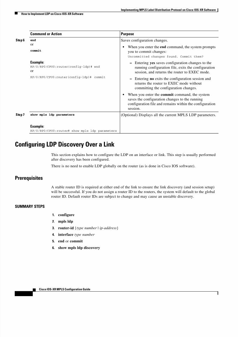
Configuring LDP Discovery Over a Link
This section explains how to configure the LDP on an interface or link. This step is usually performed
after discovery has been configured.
There is no need to enable LDP globally on the router (as is done in Cisco IOS software).
Prerequisites
A stable router ID is required at either end of the link to ensure the link discovery (and session setup)
will be successful. If you do not assign a router ID to the routers, the system will default to the global
router ID. Default router IDs are subject to change and may cause an unstable discovery.
SUMMARY STEPS
1. configure
2. mpls ldp
3. router-id {type number | ip-address}
4. interface type number 5. end or commit
6. show mpls ldp discovery
Step 6 end
or
commit
Example:RP/0/RP0/CPU0:router(config-ldp)# end
or
RP/0/RP0/CPU0:router(config-ldp)# commit
Saves configuration changes.
• When you enter the end command, the system prompts
you to commit changes:
Uncommitted changes found. Commit them?
– Entering yes saves configuration changes to the
running configuration file, exits the configuration
session, and returns the router to EXEC mode.
– Entering no exits the configuration session and
returns the router to EXEC mode without
committing the configuration changes.
• When you enter the commit command, the system
saves the configuration changes to the running
configuration file and remains within the configuration
session.
Step 7 show mpls ldp parameters
Example:RP/0/RP0/CPU0:router# show mpls ldp parameters
(Optional) Displays all the current MPLS LDP parameters.
Command or Action Purpose

8/11/2019 MPLS Configuration
http://slidepdf.com/reader/full/mpls-configuration 19/98
Implementing MPLS Label Distribution Protocol on Cisco IOS-XR Software
How to Implement LDP on Cisco IOS-XR Software
MPC-13
Cisco IOS-XR MPLS Configuration Guide
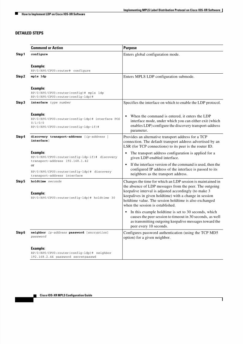
DETAILED STEPS
Command or Action Purpose
Step 1 configure
Example:RP/0/RP0/CPU0:router# configure
Enters global configuration mode.
Step 2 mpls ldp
Example:RP/0/RP0/CPU0:router(config)# mpls ldpRP/0/RP0/CPU0:router(config-ldp)#
Enters MPLS LDP configuration mode.
Step 3 router-id {type number | ip-address}
Example:
RP/0/RP0/CPU0:router(config-ldp)# router-idloopback 1
(Optional) Specifies the router ID of the local node.
• In Cisco IOS-XR, the router ID can be specified as an
interface name or IP address. By default, LDP uses the
global router ID (configured by the global router IDprocess).
Step 4 interface type number
Example:RP/0/RP0/CPU0:router(config-ldp)# interface POS0/1/0/0
RP/0/RP0/CPU0:router(config-ldp-if)#
Specifies the interface on which to enable the LDP protocol.
• When the command is entered, it displays the LDP
interface mode prompt, under which you can either exit
(which enables LDP) or configure the discovery
transport-address parameter.
Step 5 end
or
commit
Example:RP/0/RP0/CPU0:router(config-ldp-if)# end
or
RP/0/RP0/CPU0:router(config-ldp-if)# commit
Saves configuration changes.
• When you enter the end command, the system prompts
you to commit changes:
Uncommitted changes found. Commit them?
– Entering yes saves configuration changes to the
running configuration file, exits the configuration
session, and returns the router to EXEC mode.
– Entering no exits the configuration session and
returns the router to EXEC mode without
committing the configuration changes.
• When you enter the commit command, the system
saves the configuration changes to the running
configuration file and remains within the configuration
session.
Step 6 show mpls ldp discovery
Example:RP/0/RP0/CPU0:router# show mpls ldp discovery
(Optional) Displays the status of the LDP discovery
process.
• This command, without an interface filter, generates a
list of interfaces over which the LDP discovery process
is running. The output information contains the state of
the link (xmt/rcv hellos), local LDP identifier, the
discovered peer’s LDP identifier, and holdtime values.

8/11/2019 MPLS Configuration
http://slidepdf.com/reader/full/mpls-configuration 20/98
Implementing MPLS Label Distribution Protocol on Cisco IOS-XR Software
How to Implement LDP on Cisco IOS-XR Software
MPC-14
Cisco IOS-XR MPLS Configuration Guide
Configuring LDP Discovery for Active Targeted Hellos
Perform this task to configure LDP discovery for (active) targeted hellos. The active side for targeted
hellos is the side that initiates the unicast hello toward a specific destination.
Although the targeted-hello procedures are the same between Cisco IOS and Cisco IOS-XR, they are
being presented here due to their procedural importance.
Note This section works in same way as Cisco IOS targeted hellos.
Prerequisites
The following prerequisites are required to configure LDP discovery for active targeted hellos:
• A stable router ID is required at either end of the targeted session. If you do not assign a router ID
to the routers, the system will default to the global router ID. Please note that default router IDs are
subject to change and may cause an unstable discovery.
• One or more MPLS Traffic Engineering tunnels are established between non-directly connectedLSRs.
SUMMARY STEPS
1. configure
2. mpls ldp
3. router-id {type number | ip-address}
4. interface type number
5. end or commit
6. show mpls ldp discovery
DETAILED STEPS
Command or Action Purpose
Step 1 configure
Example:RP/0/RP0/CPU0:router# configure
Enters global configuration mode.
Step 2 mpls ldp
Example:RP/0/RP0/CPU0:router(config)# mpls ldpRP/0/RP0/CPU0:router(config-ldp)#
Enters MPLS LDP configuration submode.
Step 3 router-id [type number | ip-address]
Example:RP/0/RP0/CPU0:router(config-ldp)# router-idloopback 1
Specifies the router ID of the local node.
In Cisco IOS-XR, the router ID can be specified as an
interface name or IP address. By default, LDP uses the
global router ID (configured by global router ID process).

8/11/2019 MPLS Configuration
http://slidepdf.com/reader/full/mpls-configuration 21/98
Implementing MPLS Label Distribution Protocol on Cisco IOS-XR Software
How to Implement LDP on Cisco IOS-XR Software
MPC-15
Cisco IOS-XR MPLS Configuration Guide
Configuring LDP Discovery for Passive Targeted Hellos
A passive side for targeted hello is the destination router (tunnel tail), which passively waits for an
incoming hello message. Because targeted hellos are unicast, the passive side waits for an incoming hello
message to respond with hello toward its discovered neighbor.
Prerequisites
A stable router ID is required at either end of the link to ensure the link discovery (and session setup)will be successful. If you do not assign a router ID to the routers, the system will default to the global
router ID. Default router IDs are subject to change and may cause an unstable discovery.
SUMMARY STEPS
1. configure
2. mpls ldp
Step 4 interface type number
Example:RP/0/RP0/CPU0:router(config-ldp)# interface
tunnel-te 12001RP/0/RP0/CPU0:router(config-ldp-if)#
Specifies the MPLS TE tunnel interface on which to enable
the LDP protocol. It initiates a targeted Hello using unicast
towards the tunnel destination.
• When the command is entered, it enters the LDP
interface mode, under which you can either exit (which
enables LDP) configure the discovery transport-address
parameter.
Step 5 end
or
commit
Example:RP/0/RP0/CPU0:router(config-ldp-if)# end
or
RP/0/RP0/CPU0:router(config-ldp-if)# commit
Saves configuration changes.
• When you enter the end command, the system prompts
you to commit changes:
Uncommitted changes found. Commit them?
– Entering yes saves configuration changes to the
running configuration file, exits the configuration
session, and returns the router to EXEC mode.
– Entering no exits the configuration session and
returns the router to EXEC mode without
committing the configuration changes.
• When you enter the commit command, the system
saves the configuration changes to the running
configuration file and remains within the configuration
session.
Step 6 show mpls ldp discovery
Example:RP/0/RP0/CPU0:router# show mpls ldp discovery
(Optional) Displays the status of the LDP discovery
process.
• This command, without an interface filter, generates a
list of interfaces over which the LDP discovery process
is running. The output information contains the state of
the link (xmt/rcv hellos), local LDP identifier, thediscovered peer’s LDP identifier, and holdtime values.
Command or Action Purpose

8/11/2019 MPLS Configuration
http://slidepdf.com/reader/full/mpls-configuration 22/98
Implementing MPLS Label Distribution Protocol on Cisco IOS-XR Software
How to Implement LDP on Cisco IOS-XR Software
MPC-16
Cisco IOS-XR MPLS Configuration Guide
3. router-id [type number | ip-address]
4. discovery targeted-hello accept
5. end or commit
6. show mpls ldp discovery
DETAILED STEPS
Command or Action Purpose
Step 1 configure
Example:RP/0/RP0/CPU0:router# configure
Enters global configuration mode.
Step 2 mpls ldp
Example:RP/0/RP0/CPU0:router(config)# mpls ldp
RP/0/RP0/CPU0:router(config-ldp)#
Enters MPLS LDP configuration mode.
Step 3 router-id [type number | ip-address]
Example:RP/0/RP0/CPU0:router(config-ldp)# router-id
loopback 1
(Optional) Specifies the router ID of the local node.
• In Cisco IOS-XR, the router ID can be specified as an
interface name or IP address. By default, LDP uses the
global router ID (configured by global router ID
process).
Step 4 discovery targeted-hello accept
Example:RP/0/RP0/CPU0:router(config-ldp)# discovery
targeted-hello accept
Directs the system to accept targeted hello messages from a
specified interface and activates passive mode on the LSR
for targeted hello acceptance.
• This command is executed on the tail-end node (with
respect to a given MPLS TE tunnel).

8/11/2019 MPLS Configuration
http://slidepdf.com/reader/full/mpls-configuration 23/98
Implementing MPLS Label Distribution Protocol on Cisco IOS-XR Software
How to Implement LDP on Cisco IOS-XR Software
MPC-17
Cisco IOS-XR MPLS Configuration Guide
Setting Up LDP Neighbors
The following section describes how to configure an LDP session between two neighbors and how to
tune various related parameters.
Prerequisites
A stable router ID is required at either end of the link to ensure the link discovery (and session setup)
will be successful. If you do not assign a router ID to the routers, the system will default to the global
router ID. Default router IDs are subject to change and may cause an unstable discovery.
SUMMARY STEPS
1. configure
2. mpls ldp
3. interface {type number }
4. discovery transport-address [ip-address | interface]
5. holdtime seconds
6. neighbor ip-address password [encryption] password
7. backoff initial maximum
8. end or commit
9. show mpls ldp neighbor
Step 5 end
or
commit
Example:RP/0/RP0/CPU0:router(config-ldp)# end
or
RP/0/RP0/CPU0:router(config-ldp)# commit
Saves configuration changes.
• When you enter the end command, the system prompts
you to commit changes:
Uncommitted changes found. Commit them?
– Entering yes saves configuration changes to the
running configuration file, exits the configuration
session, and returns the router to EXEC mode.
– Entering no exits the configuration session and
returns the router to EXEC mode without
committing the configuration changes.
• When you enter the commit command, the system
saves the configuration changes to the running
configuration file and remains within the configuration
session.
Step 6 show mpls ldp discovery
Example:RP/0/RP0/CPU0:router# show mpls ldp discovery
(Optional) Displays the status of the LDP discovery
process.
• This command, without an interface filter, generates a
list of interfaces over which the LDP discovery process
is running. The output information contains the state of
the link (xmt/rcv hellos), local LDP identifier, the
discovered peer’s LDP identifier, and holdtime values.
Command or Action Purpose
8/11/2019 MPLS Configuration
http://slidepdf.com/reader/full/mpls-configuration 24/98
Implementing MPLS Label Distribution Protocol on Cisco IOS-XR Software
How to Implement LDP on Cisco IOS-XR Software
MPC-18
Cisco IOS-XR MPLS Configuration Guide
DETAILED STEPS
Command or Action Purpose
Step 1 configure
Example:RP/0/RP0/CPU0:router# configure
Enters global configuration mode.
Step 2 mpls ldp
Example:RP/0/RP0/CPU0:router(config)# mpls ldpRP/0/RP0/CPU0:router(config-ldp)#
Enters MPLS LDP configuration submode.
Step 3 interface type number
Example:
RP/0/RP0/CPU0:router(config-ldp)# interface POS0/1/0/0
RP/0/RP0/CPU0:router(config-ldp-if)#
Specifies the interface on which to enable the LDP protocol.
• When the command is entered, it enters the LDP
interface mode, under which you can either exit (whichenables LDP) configure the discovery transport-address
parameter.
Step 4 discovery transport-address [ip-address |
interface]
Example:RP/0/RP0/CPU0:router(onfig-ldp-if)# discoverytransport-address 192.168.1.42
or
RP/0/RP0/CPU0:router(onfig-ldp)# discovery
transport-address interface
Provides an alternative transport address for a TCP
connection. The default transport address advertised by an
LSR (for TCP connections) to its peer is the router ID.
• The transport address configuration is applied for a
given LDP-enabled interface.
• If the interface version of the command is used, then the
configured IP address of the interface is passed to its
neighbors as the transport address.
Step 5 holdtime seconds
Example:RP/0/RP0/CPU0:router(onfig-ldp)# holdtime 30
Changes the time for which an LDP session is maintained inthe absence of LDP messages from the peer. The outgoing
keepalive interval is adjusted accordingly (to make 3
keepalives in given holdtime) with a change in session
holdtime value. The session holdtime is also exchanged
when the session is established.
• In this example holdtime is set to 30 seconds, which
causes the peer session to timeout in 30 seconds, as well
as transmitting outgoing keepalive messages toward the
peer every 10 seconds.
Step 6 neighbor ip-address password [encryption]
password
Example:RP/0/RP0/CPU0:router(config-ldp)# neighbor192.168.2.44 password secretpasswd
Configures password authentication (using the TCP MD5
option) for a given neighbor.

8/11/2019 MPLS Configuration
http://slidepdf.com/reader/full/mpls-configuration 25/98
Implementing MPLS Label Distribution Protocol on Cisco IOS-XR Software
How to Implement LDP on Cisco IOS-XR Software
MPC-19
Cisco IOS-XR MPLS Configuration Guide
Setting Up LDP Forwarding
By default, the LDP control plane implements the penultimate hop popping (PHOP) mechanism. The
PHOP mechanism requires that LSR use the implicit-null label as a local label for the given Forwarding
Equivalence Class (FEC) for which LSR is the penultimate hop. Although PHOP has certain advantages,
it may be required to extend LSP up to the ultimate hop under certain circumstances (for example, to
propagate MPL QoS). This is done using a special local label (explicit-null) advertised to the peers after
which the peers use this label when forwarding traffic toward the ultimate hop (egress LSR).
Prerequisites
A stable router ID is required at either end of the link to ensure the link discovery (and session setup)
will be successful. If you do not assign a router ID to the routers, the system will default to the global
router ID. Default router IDs are subject to change and may cause an unstable discovery.
Step 7 backoff initial maximum
Example:RP/0/RP0/CPU0:router(config-ldp)# backoff 10 20
Configures the parameters for the LDP backoff mechanism.
• The LDP backoff mechanism prevents two
incompatibly configured LSRs from engaging in an
unthrottled sequence of session setup failures. If a
session setup attempt fails due to such incompatibility,
each LSR delays its next attempt (backs off), increasing
the delay exponentially with each successive failure
until the maximum backoff delay is reached.
Step 8 end
or
commit
Example:RP/0/RP0/CPU0:router(config-ldp)# end
or
RP/0/RP0/CPU0:router(config-ldp)# commit
Saves configuration changes.
• When you enter the end command, the system prompts
you to commit changes:
Uncommitted changes found. Commit them?
– Entering yes saves configuration changes to the
running configuration file, exits the configuration
session, and returns the router to EXEC mode.
–Entering no exits the configuration session and
returns the router to EXEC mode without
committing the configuration changes.
• When you enter the commit command, the system
saves the configuration changes to the running
configuration file and remains within the configuration
session.
Step 9 show mpls ldp neighbor
Example:RP/0/RP0/CPU0:router# show mpls ldp neighbor
(Optional) Displays the status of the LDP session with its
neighbors.
• This command can be run with various filters as well as
with the brief option.
Command or Action Purpose

8/11/2019 MPLS Configuration
http://slidepdf.com/reader/full/mpls-configuration 26/98
Implementing MPLS Label Distribution Protocol on Cisco IOS-XR Software
How to Implement LDP on Cisco IOS-XR Software
MPC-20
Cisco IOS-XR MPLS Configuration Guide
SUMMARY STEPS
1. configure
2. mpls ldp
3. explicit-null
4. end or commit
5. show mpls ldp forwarding
6. show mpls forwarding
7. ping ip-address
DETAILED STEPS
Command or Action Purpose
Step 1 configure
Example:RP/0/RP0/CPU0:router# configure
Enters global configuration mode.
Step 2 mpls ldp
Example:RP/0/RP0/CPU0:router(config)# mpls ldp
RP/0/RP0/CPU0:router(config-ldp)#
Enters MPLS LDP configuration submode.
Step 3 explicit-null
Example:RP/0/RP0/CPU0:router(config-ldp)# explicit-null
Causes a router to advertise an explicit null label in
situations where it would normally advertise an implicit
null label (for example, to enable an ultimate-hop
disposition instead of PHOP).
Step 4 end
or
commit
Example:RP/0/RP0/CPU0:router(config-ldp)# end
or
RP/0/RP0/CPU0:router(config-ldp)# commit
Saves configuration changes.
• When you enter the end command, the system prompts
you to commit changes:
Uncommitted changes found. Commit them?
– Entering yes saves configuration changes to the
running configuration file, exits the configuration
session, and returns the router to EXEC mode.
– Entering no exits the configuration session and
returns the router to EXEC mode without
committing the configuration changes.
• When you enter the commit command, the systemsaves the configuration changes to the running
configuration file and remains within the configuration
session.
Step 5 show mpls ldp forwarding
Example:RP/0/RP0/CPU0:router# show mpls ldp forwarding
(Optional) Displays the MPLS LDP view of installed
forwarding states (rewrites).
8/11/2019 MPLS Configuration
http://slidepdf.com/reader/full/mpls-configuration 27/98
Implementing MPLS Label Distribution Protocol on Cisco IOS-XR Software
How to Implement LDP on Cisco IOS-XR Software
MPC-21
Cisco IOS-XR MPLS Configuration Guide
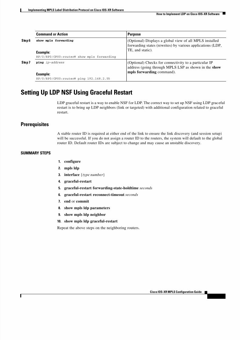
Setting Up LDP NSF Using Graceful Restart
LDP graceful restart is a way to enable NSF for LDP. The correct way to set up NSF using LDP graceful
restart is to bring up LDP neighbors (link or targeted) with additional configuration related to graceful
restart.
Prerequisites
A stable router ID is required at either end of the link to ensure the link discovery (and session setup)
will be successful. If you do not assign a router ID to the routers, the system will default to the global
router ID. Default router IDs are subject to change and may cause an unstable discovery.
SUMMARY STEPS
1. configure
2. mpls ldp
3. interface {type number }
4. graceful-restart
5. graceful-restart forwarding-state-holdtime seconds
6. graceful-restart reconnect-timeout seconds
7. end or commit
8. show mpls ldp parameters
9. show mpls ldp neighbor
10. show mpls ldp graceful-restart
Repeat the above steps on the neighboring routers.
Step 6 show mpls forwarding
Example:RP/0/RP0/CPU0:router# show mpls forwarding
(Optional) Displays a global view of all MPLS installed
forwarding states (rewrites) by various applications (LDP,
TE, and static).
Step 7 ping ip-address
Example:RP/0/RP0/CPU0:router# ping 192.168.2.55
(Optional) Checks for connectivity to a particular IP
address (going through MPLS LSP as shown in the show
mpls forwarding command).
Command or Action Purpose

8/11/2019 MPLS Configuration
http://slidepdf.com/reader/full/mpls-configuration 28/98

8/11/2019 MPLS Configuration
http://slidepdf.com/reader/full/mpls-configuration 29/98
Implementing MPLS Label Distribution Protocol on Cisco IOS-XR Software
How to Implement LDP on Cisco IOS-XR Software
MPC-23
Cisco IOS-XR MPLS Configuration Guide
Step 7 end
or
commit
Example:RP/0/RP0/CPU0:router(config-ldp)# end
or
RP/0/RP0/CPU0:router(config-ldp)# commit
Saves configuration changes.
• When you enter the end command, the system prompts
you to commit changes:
Uncommitted changes found. Commit them?
– Entering yes saves configuration changes to the
running configuration file, exits the configuration
session, and returns the router to EXEC mode.
– Entering no exits the configuration session and
returns the router to EXEC mode without
committing the configuration changes.
• When you enter the commit command, the system
saves the configuration changes to the running
configuration file and remains within the configuration
session.
Step 8 show mpls ldp parameters
Example:RP/0/RP0/CPU0:router# show mpls ldp parameters
(Optional) Displays all the current MPLS LDP parameters.
Step 9 show mpls ldp neighbor
Example:RP/0/RP0/CPU0:router# show mpls ldp neighbor
(Optional) Displays the status of the LDP session with its
neighbors.
• This command can be run with various filters as well as
with the brief option.
Step 10 show mpls ldp graceful-restart
Example:RP/0/RP0/CPU0:router# show mpls ldp
graceful-restart
(Optional) Displays the status of the LDP graceful restart
feature.
• The output of this command not only shows states of
different graceful restart timers, but also a list of
graceful restart neighbors, their state, and reconnect
count.
Command or Action Purpose

8/11/2019 MPLS Configuration
http://slidepdf.com/reader/full/mpls-configuration 30/98
Implementing MPLS Label Distribution Protocol on Cisco IOS-XR Software
Configuration Examples for Implementing LDP
MPC-24
Cisco IOS-XR MPLS Configuration Guide
Configuration Examples for Implementing LDPThis section provides the following configuration examples:
• Configuring LDP with Graceful Restart: Example, page MPC-24
• Configuring LDP Discovery: Example, page MPC-24• Configuring LDP Link: Example, page MPC-24
• Configuring LDP Discovery for Targeted Hellos: Example, page MPC-25
• Configuring for LDP Neighbors: Example, page MPC-25
• Configuring MPLS LDP Forwarding: Example, page MPC-25
• Configuring LDP Non-Stop Forwarding with Graceful Restart: Example, page MPC-25
Configuring LDP with Graceful Restart: Example
The following example shows how to enable LDP with graceful restart on the POS interface 0/2/0/0:
mpls ldp graceful-restart
interface pos0/2/0/0 end
Configuring LDP Discovery: Example
The following example shows how to configure LDP discovery parameters:
configure
mpls ldp
router-id loopback0 discovery hello holdtime 15
discovery hello interval 5
end
!show mpls ldp parameters
!show mpls ldp discovery
Configuring LDP Link: Example
The following example shows how to configure LDP link parameters:
configure
mpls ldp interface pos 0/1/0/0
end!
show mpls ldp discovery

8/11/2019 MPLS Configuration
http://slidepdf.com/reader/full/mpls-configuration 31/98
Implementing MPLS Label Distribution Protocol on Cisco IOS-XR Software
Configuration Examples for Implementing LDP
MPC-25
Cisco IOS-XR MPLS Configuration Guide
Configuring LDP Discovery for Targeted Hellos: Example
The following example shows how to configure LDP Discovery to accept targeted hello messages:
Active: (tunnel head)
configure mpls ldp
router-id loopback0 interface tunnel-te 12001
end
Passive: (tunnel tail)
configure
mpls ldp router-id loopback0
discovery targeted-hello accept
end
Configuring for LDP Neighbors: Example
The following example shows how to configure LDP neighbors:
configure
mpls ldp
neighbor password psswd
backoff 10 20 interface pos0/1/0/0
endUncommitted changes found, commit them? [yes]: yes
Configuring MPLS LDP Forwarding: Example
The following example shows how to configure LDP forwarding:
configure
mpls ldp explicit-null
end
Uncommitted changes found, commit them? [yes]: yes
!show mpls ldp forwarding
!show mpls forwarding
Configuring LDP Non-Stop Forwarding with Graceful Restart: Example
The following example shows how to configure LDP nonstop forwarding with graceful restart:
configure mpls ldp
graceful-restart
graceful-restart forwarding state-holdtime 180

8/11/2019 MPLS Configuration
http://slidepdf.com/reader/full/mpls-configuration 32/98
Implementing MPLS Label Distribution Protocol on Cisco IOS-XR Software
Where to Go Next
MPC-26
Cisco IOS-XR MPLS Configuration Guide
graceful-restart reconnect-timeout 15
interface pos0/1/0/0
endUncommitted changes found, commit them? [yes]: yes
!show mpls ldp graceful-restart
Where to Go NextAfter implementing LDP you may want to consult the following publications:
• Implementing RSVP for MPLS-TE and MPLS O-UNI on Cisco IOS-XR Software
• Implementing MPLS Traffic Engineering on Cisco IOS-XR Software
• Implementing MPLS Optical User Network Interface Protocol on Cisco IOS-XR Software
• Implementing MPLS Forwarding on Cisco IOS-XR Software
Additional ReferencesFor additional information related to Implementing MPLS Label Distribution Protocol, refer to the
following references:
Related Documents
Standards
Related Topic Document Title
Cisco IOS-XR LDP commands MPLS Label Distribution Protocol Commands on Cisco IOS-XR
Software
IOS MPLS overview Multiprotocol Label Switching Overview
IOS MPLS configuration Configuring Multiprotocol Label Switching
Standards1
1. Not all supported standards are listed.
Title
No new or modified standards are supported by the
features in this document, and support for existing
standards had not been modified by the features in this
document.

8/11/2019 MPLS Configuration
http://slidepdf.com/reader/full/mpls-configuration 33/98
Implementing MPLS Label Distribution Protocol on Cisco IOS-XR Software
Additional References
MPC-27
Cisco IOS-XR MPLS Configuration Guide
MIBs
RFCs
Technical Assistance
MIBs1
1. Not all supported MIBs are listed.
MIBs Link
None To locate and download MIBs for selected platforms, Cisco IOS
releases, and feature sets, use Cisco MIB Locator found at the
following URL:
http://www.cisco.com/go/mibs
RFCs1
1. Not all supported RFCs are listed.
Title
RFC 3031 Multiprotocol Label Switching Architecture
RFC 3036 LDP Speci fication
RFC 3037 LDP Applicability
RFC 3478 Graceful Restart Mechanism for Label Distribution Protocol
Description Link
Technical Assistance Center (TAC) home page,
containing 30,000 pages of searchable technical
content, including links to products, technologies,
solutions, technical tips, and tools. RegisteredCisco.com users can log in from this page to access
even more content.
http://www.cisco.com/public/support/tac/home.shtml

8/11/2019 MPLS Configuration
http://slidepdf.com/reader/full/mpls-configuration 34/98
Implementing MPLS Label Distribution Protocol on Cisco IOS-XR Software
Glossary
MPC-28
Cisco IOS-XR MPLS Configuration Guide
GlossaryAAA—authentication, authorization, and accounting.
API—application programming interface. The means by which an application program talks to
communications software. Standardized APIs allow application programs to be developed independently
of the underlying method of communication. A set of standard software interrupts, calls, and data
formats that computer application programs use to initiate contact with other devices (for example,
network services, mainframe communications programs, or other program-to-program
communications).
CE router—customer edge router. A router that is part of a customer network and that interfaces to a
provider edge (PE) router.
CoS—class of service. An indication of how an upper-layer protocol requires a lower-layer protocol to
treat its messages. In SNA subarea routing, CoS definitions are used by subarea nodes to determine the
optimal route to establish a given session. A CoS definition comprises a virtual route number and a
transmission priority field.
CSPF—Constrained Shortest Path First. A routing algorithm used in MPLS-TE.
DPM—call defect per million. Lost stable (connected call) or non-stable (call being setup) call due toany hardware or software failure, procedural error, or other causes. Note that a Call Defect does not
include misrouted calls or loss of call features.
DRP—Distributed Route Processor. In the Cisco CRS-1 Carrier Routing System, the DRP is a service
card that can handle routing, MPLS, or FCAPS management functionality.
DSCP—Differentiated Service Code Point.
DS-TE—Diff-Serv aware traffic engineering feature that supports different bandwidth constraints for
different traffic classes using Diff-Serv model with bandwidth pools. In combination with other features,
this may be used to achieve MPLS Guaranteed Bandwidth services.
DWDM—Dense Wave Division Multiplexing.
ERO—Explicit Route Object. One of the fields in RSVP messages. It specifies the route that the RSVPtunnel should take.
FCAPS—Fault, configuration, accounting, performance, and security.
FEC—Forwarding Equivalence Class.
FIB—Forwarding Information Base. Table that is used on the line card to prepare the packet for
forwarding.
FRR—Fast Reroute.
FT—fault tolerant.
Generalized MPLS—Extensions to the protocols used for control of MPLS-TE LSPs, which support
the use of a variety of switching techniques.
GMPLS-TE—Generalized MPLS Traffic Engineering.GR—Graceful Restart.
HA—High Availability.
IPCC—IP Control Channel.
ICMP—Internet Control Message Protocol.
IETF—Internet Engineering Task Force.
IGP—Interior Gateway Protocol. A class of routing protocol.

8/11/2019 MPLS Configuration
http://slidepdf.com/reader/full/mpls-configuration 35/98
Implementing MPLS Label Distribution Protocol on Cisco IOS-XR Software
Glossary
MPC-29
Cisco IOS-XR MPLS Configuration Guide
IM—Interface Manager
IOS—Cisco’s Internetwork Operating System.
IPC—interprocess communications. This mechanism makes it possible to create large systems that are
complex in function, yet simple and streamlined in design.
LC—line card.
LDP—Label Distribution Protocol
LIB—Label Information Base. The table that contains the labels in use on the node.
LM—link manager.
LSA—link-state advertisement. Broadcast packet used by link-state protocols that contains information
about neighbors and path costs. LSAs are used by the receiving routers to maintain their routing tables.
LSD—label switching database.
LSP—label switched path. a sequence of hops along which packets are forwarded using MPLS
mechanisms. Dynamic label switched paths are typically used to forward packets across networks using
labels advertised via LDP for routing prefixes. Static LSPs are typically used to forward packets along
traffic engineered paths.
LSP Tunnel / MPLS TE Tunnel—A tunnel that uses static LSPs to forward packets to the destination.
This phrase is often used in the abstract sense, with emphasis on the fact that the tunnel is using an LSP
to forward data, but without emphasis on the implementation of the tunnel itself.
LSR—label switch router. The role of an LSR is to forward packets in an MPLS network by looking
only at the fixed-length label.
MAC—Media Access Control.
MIB—Management Information Base. Database of network management information that is used and
maintained by a network management protocol, such as SNMP or CMIP.
MP—merge point (in fast rerouting).
MPLS—Multiprotocol Label Switching. Switching method that forwards IP traffic using a label. This
label instructs the routers and the switches in the network where to forward the packets based onpreestablished IP routing information.
MPlS—Multiprotocol lambda switching. Also known as Generalized MPLS.
MPLS-TE—MPLS traffic engineering.
NSF—Non-stop forwarding. Generic table mechanism in which the goal is to have continuous packet
forwarding despite failures in the system control plane (routing protocols and others).
PHOP—penultimate hop popping mechanism.
QoS—quality of service.
RIB—Routing Information Base.
RP—Route Processor. In a distributed system, the RP is where all the routing protocol processes run.
RSVP—Resource Reservation Protocol. Protocol that supports the reservation of resources across an IP
network. Applications running on IP end systems can use RSVP to indicate to other nodes the nature
(bandwidth, jitter, maximum burst, and so on) of the packet streams they want to receive. RSVP depends
on IPv6.
TE—traffic engineering. Mechanisms used to cause certain data packets to follow a predetermined path
through the network, other than that which the IGP specifies as being the current shortest path.
TED—traffic engineering database.

8/11/2019 MPLS Configuration
http://slidepdf.com/reader/full/mpls-configuration 36/98
Implementing MPLS Label Distribution Protocol on Cisco IOS-XR Software
Glossary
MPC-30
Cisco IOS-XR MPLS Configuration Guide
TLV—typed length value. TLV advertises the reconnect time, recovery time, and FT flag to a node’s
peers.
VC—virtual circuit.
VPN—virtual private network.
VRF—VPN routing/forwarding instance.
Copyright © 2004 Cisco Systems, Inc. All rights reserved.
CIP, CCSP, the Cisco Arrow logo, the Cisco Powered Network mark, Cisco Unity, Follow Me Browsing, FormShare, and StackWise are trademarks of
isco Systems, Inc.; Changing the Way We Work, Live, Play, and Learn, and iQuick Study are service marks of Cisco Systems, Inc.; and Aironet, ASIST,
BPX, Catalyst, CCDA, CCDP, CCIE, CCNA, CCNP, Cisco, the Cisco Certified Internetwork Expert logo, Cisco IOS, the Cisco IOS logo, Cisco Press,
isco Systems, Cisco Systems Capital, the Cisco Systems logo, Empowering the Internet Generation, Enterprise/Solver, EtherChannel, EtherFast,
EtherSwitch, Fast Step, GigaDrive, GigaStack, HomeLink, Internet Quotient, IOS, IP/TV, iQ Expertise, the iQ logo, iQ Net Readiness Scorecard,
LightStream, Linksys, MeetingPlace, MGX, the Networkers logo, Networking Academy, Network Registrar, Packet , PIX, Post-Routing, Pre-Routing,
ProConnect, RateMUX, Registrar, ScriptShare, SlideCast, SMARTnet, StrataView Plus, SwitchProbe, TeleRouter, The Fastest Way to Increase Your
Internet Quotient, TransPath, and VCO are registered trademarks of Cisco Systems, Inc. and/or its affiliates in the United States and certain other
ountries.
All other trademarks mentioned in this document or Website are the property of their respective owners. The use of the word partner does not imply a
artnership relationship between Cisco and any other company. (0403R)

8/11/2019 MPLS Configuration
http://slidepdf.com/reader/full/mpls-configuration 37/98
Corporate Headquarters:
Copyright © 2004 Cisco Systems, Inc. All rights reserved.
Cisco Systems, Inc., 170 West Tasman Drive, San Jose, CA 95134-1706 USA
Implementing MPLS Traffic Engineering onCisco IOS-XR Software
Multiprotocol Label Switching (MPLS) is a standards-based solution driven by the Internet Engineering
Task Force (IETF) that was devised to convert the Internet and IP backbones from best-effort networks
into business-class transport mediums.
MPLS, with its label switching capabilities, eliminates the need for an IP route look-up and creates a
virtual circuit (VC) switching function, allowing enterprises the same performance on their IP-based
network services as with those delivered over traditional networks such as Frame Relay or Asynchronous
Transfer Mode (ATM).
MPLS traffic engineering software enables an MPLS backbone to replicate and expand upon the traffic
engineering capabilities of Layer 2 ATM and Frame Relay networks. MPLS is an integration of Layer 2
and Layer 3 technologies. By making traditional Layer 2 features available to Layer 3, MPLS enables
traffic engineering. Thus, you can offer in a one-tier network what now can be achieved only by
overlaying a Layer 3 network on a Layer 2 network.
Feature History for the Cisco MPLS-TE Feature
Contents• Prerequisites for Implementing Cisco MPLS Traffic Engineering, page MPC-32
• Information About Implementing MPLS Traffic Engineering, page MPC-32
• How to Implement Traffic Engineering on Cisco IOS-XR, page MPC-36
• Configuration Examples for Cisco MPLS Traffic Engineering, page MPC-48• Additional References, page MPC-50
• Glossary, page MPC-52
Feature HistoryRelease Modification
Release 2.0 This feature was introduced.

8/11/2019 MPLS Configuration
http://slidepdf.com/reader/full/mpls-configuration 38/98
Implementing MPLS Traffic Engineering on Cisco IOS-XR Software
Prerequisites for Implementing Cisco MPLS Traffic Engineering
MPC-32
Cisco IOS-XR MPLS Configuration Guide
Prerequisites for Implementing Cisco MPLS Traffic EngineeringThe following are required to implement MPLS-TE on the Cisco HFR router:
• A router that runs Cisco IOS-XR software.
• An installed composite mini-image and the MPLS package, or a full composite image.• IGP activated on the router.
• The Task ID mpls-te—the user must be set up with these task privileges:
– The read privilege for show and debug commands.
– The read and write privileges for any action commands (such as clear, EXEC, or test).
Information About Implementing MPLS Traffic EngineeringTo implement MPLS-TE you must understand the following concepts:
• Comparison of Cisco IOS MPLS-TE and Cisco IOS-XR MPLS-TE, page MPC-32• Overview of MPLS Traffic Engineering, page MPC-33
• Protocol-Based CLI, page MPC-34
• Differentiated Services Traffic Engineering, page MPC-34
• Fast Reroute, page MPC-35
• How to Implement Traffic Engineering on Cisco IOS-XR, page MPC-36
Comparison of Cisco IOS MPLS-TE and Cisco IOS-XR MPLS-TE
The following characteristics and features of MPLS-TE are similar on both Cisco IOS software and
Cisco IOS-XR software:
• MPLS-TE topology.
• Path calculation (PCALC).
• Differentiated Services Traffic Engineering (DS-TE).
• Fast reroute.
• Flooding.
The following characteristics and features of MPLS-TE are new in Cisco IOS-XR software:
• New configuration modes.
• Protocol-based command line interface (CLI).
• Task IDs are implemented for a new level of system control.
• Router IDs are configured globally, unless they are overridden using the mpls traffic-eng router-id
command.
• New show commands to facilitate Cisco IOS-XR software operation.
• While MPLS-TE tunnel functionality is similar to Cisco IOS software, Cisco IOS-XR software
features a new interface tunnel-te command and eliminates the tunnel mode mpls traffic-eng mode.
• Elimination of the mpls traffic-eng tunnels command.

8/11/2019 MPLS Configuration
http://slidepdf.com/reader/full/mpls-configuration 39/98
Implementing MPLS Traffic Engineering on Cisco IOS-XR Software
Information About Implementing MPLS Traffic Engineering
MPC-33
Cisco IOS-XR MPLS Configuration Guide
Overview of MPLS Traffic Engineering
MPLS traffic engineering software enables an MPLS backbone to replicate and expand upon the traffic
engineering capabilities of Layer 2 ATM and Frame Relay networks. MPLS is an integration of Layer 2
and Layer 3 technologies. By making traditional Layer 2 features available to Layer 3, MPLS enables
traffic engineering. Thus, you can offer in a one-tier network what now can be achieved only byoverlaying a Layer 3 network on a Layer 2 network.
Traffic engineering is essential for service provider and Internet service provider (ISP) backbones. Such
backbones must support a high use of transmission capacity, and the networks must be very resilient so
that they can withstand link or node failures. MPLS traffic engineering provides an integrated approach
to traffic engineering. With MPLS, traffic engineering capabilities are integrated into Layer 3, which
optimizes the routing of IP traffic, given the constraints imposed by backbone capacity and topology.
Benefits of MPLS Traffic Engineering
Traffic engineering enables ISPs to route network traffic to offer the best service to their users in terms
of throughput and delay. By making the service provider more efficient, traffic engineering reduces the
cost of the network.
Currently, some ISPs base their services on an overlay model. In the overlay model, transmission
facilities are managed by Layer 2 switching. The routers see only a fully meshed virtual topology,
making most destinations appear one hop away. If you use the explicit Layer 2 transit layer, you can
precisely control how traffic uses available bandwidth. However, the overlay model has numerous
disadvantages. MPLS traffic engineering achieves the traffic engineering benefits of the overlay model
without running a separate network, and without needing a non-scalable, full mesh of router
interconnects.
How MPLS Traffic Engineering Works
MPLS traffic engineering automatically establishes and maintains label switched paths (LSPs) across the
backbone by using resource reservation protocol (RSVP). The path that an LSP uses is determined bythe LSP resource requirements and network resources, such as bandwidth. Available resources are
flooded by means of extensions to a link-state-based Interior Gateway Protocol (IGP).
Traffic engineering tunnels are calculated at the LSP head router based on a fit between the required and
available resources (constraint-based routing). The IGP automatically routes the traffic onto these LSPs
Typically, a packet crossing the MPLS traffic engineering backbone travels on a single LSP that connects
the ingress point to the egress point. MPLS traffic engineering is built on the following Cisco IOS
mechanisms:
• IP tunnel interfaces—From a Layer 2 standpoint, an MPLS tunnel interface represents the head of
an LSP. It is configured with a set of resource requirements, such as bandwidth and media
requirements, and priority. From a Layer 3 standpoint, an LSP tunnel interface is the head-end of a
unidirectional virtual link to the tunnel destination.• MPLS traffic engineering path calculation module—This calculation module operates at the LSP
head. The module determines a path to use for an LSP. The path calculation uses a link-state
database containing flooded topology and resource information.
• RSVP with traffic engineering extensions—RSVP operates at each LSP hop and is used to signal
and maintain LSPs based on the calculated path.

8/11/2019 MPLS Configuration
http://slidepdf.com/reader/full/mpls-configuration 40/98
Implementing MPLS Traffic Engineering on Cisco IOS-XR Software
Information About Implementing MPLS Traffic Engineering
MPC-34
Cisco IOS-XR MPLS Configuration Guide
• MPLS traffic engineering link management module—This module operates at each LSP hop,
performs link call admission on the RSVP signaling messages, and performs bookkeeping on
topology and resource information to be flooded.
• Link-state IGP (Intermediate System-to-Intermediate System [IS-IS] or Open Shortest Path First
[OSPF]—each with traffic engineering extensions)—These IGPs are used to globally flood topology
and resource information from the link management module.• Enhancements to the shortest path first (SPF) calculation used by the link-state IGP (IS-IS or
OSPF)—The IGP automatically routes traffic onto the appropriate LSP tunnel, based on tunnel
destination. Static routes can also be used to direct traffic onto LSP tunnels.
• Label switching forwarding—This forwarding mechanism provides routers with a Layer 2-like
ability to direct traffic across multiple hops of the LSP established by RSVP signaling.
One approach to engineering a backbone is to define a mesh of tunnels from every ingress device to every
egress device. The MPLS traffic engineering path calculation and signaling modules determine the path
taken by the LSPs for these tunnels, subject to resource availability and the dynamic state of the network.
The IGP, operating at an ingress device, determines which traffic should go to which egress device, and
steers that traffic into the tunnel from ingress to egress. A flow from an ingress device to an egress device
might be so large that it cannot fit over a single link, so it cannot be carried by a single tunnel. In thiscase, multiple tunnels between a given ingress and egress can be configured, and the flow is distributed
using load sharing among the tunnels.
Protocol-Based CLI
Cisco IOS-XR software provides a protocol-based command line interface. The CLI provides commands
that can be used with the multiple IGP protocols supported by MPLS traffic engineering.
Differentiated Services Traffic Engineering
MPLS Differentiated Services (diff-serv) aware Traffic Engineering (DS-TE) is an extension of the
regular MPLS Traffic Engineering (TE) feature. Regular traffic engineering does not provide bandwidth
guarantees to different traffic classes. A single bandwidth pool (global pool) is used in regular TE that
is shared by all traffic. In order to support various classes of service (CoS), you must have the ability to
provide multiple bandwidth pools. These bandwidth pools then can be treated differently based on the
requirement for the traffic class using that pool.
MPLS diff-serv traffic engineering provides the ability to configure global and subpool(s) to provide
reservable bandwidths on an interface basis.
When a TE tunnel is configured to use one of these bandwidth pools, available bandwidth from all
configured bandwidth pools is advertised via IGP. Path calculation and admission control then takes the
bandwidth pool type into consideration. RSVP is used to signal the TE tunnel with bandwidth pool
requirements.
Flooding
Available bandwidth in all configured bandwidth pools is flooded onto the network in order to calculate
accurate constraint paths when a new TE tunnel is configured. Flooding uses IGP protocol extensions
and mechanisms to determine when to flood the network with bandwidth.

8/11/2019 MPLS Configuration
http://slidepdf.com/reader/full/mpls-configuration 41/98
Implementing MPLS Traffic Engineering on Cisco IOS-XR Software
Information About Implementing MPLS Traffic Engineering
MPC-35
Cisco IOS-XR MPLS Configuration Guide
Flooding Triggers
TE Link Management (TE-Link) notifies IGP for both global pool and subpool available bandwidth and
maximum bandwidth to flood the network in the following events:
• The periodic timer expires (this does not depend on bandwidth pool type).
• The tunnel origination node has out-of-date information for either available global pool, or subpoolbandwidth, causing tunnel admission failure at the midpoint.
• Consumed bandwidth crosses user configured thresholds. The same threshold is used for both global
pool and subpool. If one bandwidth crosses the threshold, both bandwidths will be flooded.
Flooding Thresholds
Flooding frequently can burden a network because all routers must send out and process these updates.
Infrequent flooding causes tunnel heads (tunnel-originating nodes) to have out-of-date information,
causing tunnel admission to fail at the midpoints.
You can control the frequency of flooding by configuring a set of thresholds. When locked bandwidth
(at one or more priority levels) crosses one of these thresholds, flooding is triggered.Thresholds apply to a percentage of the maximum available bandwidth (the global pool), which is
locked, and the percentage of maximum available guaranteed bandwidth (the subpool), which is locked.
If, for one or more priority levels, either of these percentages crosses a threshold, flooding is triggered.
Note Setting up a global pool TE tunnel may cause the locked bandwidth allocated to subpool tunnels to be
reduced (and hence to cross a threshold). A subpool TE tunnel setup may similarly cause the locked
bandwidth for global pool TE tunnels to cross a threshold. Thus, subpool TE and global pool TE tunnels
may affect each other when flooding is triggered by thresholds.
Fast RerouteFast Reroute (FRR) provides link protection to LSPs enabling the traffic carried by LSPs that encounter
a failed link to be rerouted around the failure. The reroute decision is controlled locally by the router
connected to the failed link. The headend router on the tunnel is notified of the link failure through IGP
or through RSVP. When it is notified of a link failure, the headend router attempts to establish a new
LSP that bypasses the failure. This provides a path to reestablish links that fail, providing protection to
data transfer.
FRR (link, node, or path protection) is supported over subpool tunnels the same way as for regular TE
tunnels. In particular, when link protection is activated for a given link, TE tunnels eligible for FRR get
redirected into the protection LSP regardless of whether they are subpool or global pool tunnels.
Note The ability to configure FRR on a per-LSP basis, it is possible to effectively provide different levels of
fast restoration to tunnels from different bandwidth pools.

8/11/2019 MPLS Configuration
http://slidepdf.com/reader/full/mpls-configuration 42/98
Implementing MPLS Traffic Engineering on Cisco IOS-XR Software
How to Implement Traffic Engineering on Cisco IOS-XR
MPC-36
Cisco IOS-XR MPLS Configuration Guide
How to Implement Traffic Engineering on Cisco IOS-XRTraffic engineering requires coordination among several global neighbor routers, creating traffic
engineering tunnels, setting up forwarding across traffic engineering tunnels, setting up FRR, and
creating differential service. This section explains the following procedures:
• Building MPLS-TE Topology, page MPC-36
• Creating an MPLS-TE Tunnel, page MPC-39
• Forwarding over the MPLS-TE Tunnel, page MPC-42
• Protecting the MPLS Tunnel with Fast Reroute, page MPC-44
• Creating a Diff-Serv (Differentiated Services) TE Tunnel, page MPC-46
Building MPLS-TE Topology
Perform this task to configure MPLS-TE topology, which is required for traffic engineering tunnel
operations. Building the MPLS-TE topology is done in the following basic steps:
• Enabling MPLS-TE on the port interface.
• Enabling RSVP on the port interface.
• Enabling an IGP such as OSPF or IS-IS for MPLS-TE.
Prerequisites
The following are the requirements for traffic engineering:
• You must have a router ID for the neighbor router being linked in order to configure discovery for
the local router.
• A stable router ID is required at either end of the link to ensure the link will be successful. If you
do not assign a router ID to the routers, the system will default to the global router ID as it does in
Cisco IOS software. Default router IDs are subject to change causing an unstable link.
• If you are going to use non-default holdtime or intervals, you must decide the values to which they
will be set.
SUMMARY STEPS
1. configure
2. mpls traffic-eng
3. interface type number
4. router-id {interface-name | ip-address}
5. router ospf instance-name
6. router-id {interface-name | ip-address}
7. area area-id
8. interface type number
9. interface interface-name
10. mpls traffic-eng router-id

8/11/2019 MPLS Configuration
http://slidepdf.com/reader/full/mpls-configuration 43/98
Implementing MPLS Traffic Engineering on Cisco IOS-XR Software
How to Implement Traffic Engineering on Cisco IOS-XR
MPC-37
Cisco IOS-XR MPLS Configuration Guide
11. mpls traffic-eng area area-id
12. rsvp
13. interface type number
14. bandwidth bandwidth
15. end or commit
16. show mpls traffic topology
17. show mpls traffic-eng link-management advertisements
DETAILED STEPS
Command or Action Purpose
Step 1 configure
Example:
configure
Enters the configuration mode.
Step 2 mpls traffic-eng
Example:RP/0/RP0/CPU0:router(config)# mpls traffic-eng
Enters the mpls traffic-engineering configuration mode.
Step 3 interface type number
Example:RP/0/RP0/CPU0:router(config-mpls-te)# interface
POS0/6/0/0
Enters the MPLS traffic-engineering interface configuration
mode, and enables traffic engineering on a particular
interface on the originating node. In this case, POS interface
0/6/0/0.
Step 4 router id {interface-name | ip-address}
Example:RP/0/RP0/CPU0:router(config)# router id
loopback0
Specifies the router ID of the local node.
• In Cisco IOS-XR software, the router ID can be
specified with an interface name or an IP address. By
default, MPLS uses the global router ID, the same as
Cisco IOS software.
Step 5 router ospf instance-name
Example:RP/0/RP0/CPU0:router(config)# router ospf 1
Configures an OSPF routing instance.
• Enter the IGP submode and configure the area and
interface for an IGP such as OSPF or IS-IS.
Step 6 router-id {interface-name | ip-address}
Example:
RP/0/RP0/CPU0:router(config-router)# router-id192.168.25.66
Configures a router ID for the OSPF process using an IP
address.
Step 7 area area-id
Example:RP/0/RP0/CPU0:router(config-router)# area 0
Configures an area for the OSPF process.
• Backbone areas have an area ID of 0.
• Non-backbone areas have a non-zero area ID.

8/11/2019 MPLS Configuration
http://slidepdf.com/reader/full/mpls-configuration 44/98
Implementing MPLS Traffic Engineering on Cisco IOS-XR Software
How to Implement Traffic Engineering on Cisco IOS-XR
MPC-38
Cisco IOS-XR MPLS Configuration Guide
Step 8 interface type number
Example:RP/0/RP0/CPU0:router(config-ospf-ar)# interface
pos 0/6/0/0
Configures one or more interfaces for the area configured in
Step 7.
Step 9 interface interface-name
Example:RP/0/RP0/CPU0:router(config-ospf-ar)# interfaceloopback 0
Enables IGP on the loopback0 MPLS router ID.
Step 10 mpls traffic-eng router-id loopback 0
Example:RP/0/RP0/CPU0:router(config-router)# mpls
traffic-eng router-id loopback 0
Sets the MPLS traffic engineering loopback interface.
Step 11 mpls traffic-eng area area-id
Example:RP/0/RP0/CPU0:router(config-router)# mpls
traffic-eng area 0
Sets the MPLS traffic engineering area.
Step 12 rsvp
Example:RP/0/RP0/CPU0:router(config)# rsvp
Enables RSVP, and enters the RSVP configuration
submode.
Step 13 interface type number
Example:RP/0/RP0/CPU0:router(config-rsvp)# pos 0/6/0/0
Enters RSVP interface submode, and enables RSVP on a
particular interface on the originating node. In this case, on
the POS interface 0/6/0/0.
Step 14 bandwidth bandwidth
Example:RP/0/RP0/CPU0:router(config-rsvp-if)# bandwidth
100
Sets the reserved RSVP bandwidth available on this
interface. Physical interface bandwidth is not used by
MPLS traffic-engineering.
Command or Action Purpose
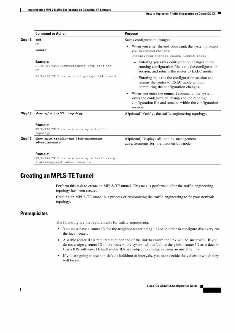
8/11/2019 MPLS Configuration
http://slidepdf.com/reader/full/mpls-configuration 45/98
Implementing MPLS Traffic Engineering on Cisco IOS-XR Software
How to Implement Traffic Engineering on Cisco IOS-XR
MPC-39
Cisco IOS-XR MPLS Configuration Guide
Creating an MPLS-TE TunnelPerform this task to create an MPLS-TE tunnel. This task is performed after the traffic engineering
topology has been created.
Creating an MPLS-TE tunnel is a process of customizing the traffic engineering to fit your network
topology.
Prerequisites
The following are the requirements for traffic engineering:
• You must have a router ID for the neighbor router being linked in order to configure discovery for
the local router.
• A stable router ID is required at either end of the link to ensure the link will be successful. If you
do not assign a router ID to the routers, the system will default to the global router ID as it does in
Cisco IOS software. Default router IDs are subject to change causing an unstable link.
• If you are going to use non-default holdtime or intervals, you must decide the values to which they
will be set.
Step 15 end
or
commit
Example:RP/0/RP0/CPU0:router(config-rsvp-if)# end
or
RP/0/RP0/CPU0:router(config-rsvp-if)# commit
Saves configuration changes.
• When you enter the end command, the system prompts
you to commit changes:
Uncommitted changes found. Commit them?
– Entering yes saves configuration changes to the
running configuration file, exits the configuration
session, and returns the router to EXEC mode.
– Entering no exits the configuration session and
returns the router to EXEC mode without
committing the configuration changes.
• When you enter the commit command, the system
saves the configuration changes to the running
configuration file and remains within the configuration
session.
Step 16 show mpls traffic topology
Example:RP/0/RP0/CPU0:router# show mpls traffic
topology
(Optional) Verifies the traffic engineering topology.
Step 17 show mpls traffic-eng link-management
advertisements
Example:RP/0/RP0/CPU0:router# show mpls traffic-eng
link-management advertisements
(Optional) Displays all the link-management
advertisements for the links on this node.
Command or Action Purpose

8/11/2019 MPLS Configuration
http://slidepdf.com/reader/full/mpls-configuration 46/98
Implementing MPLS Traffic Engineering on Cisco IOS-XR Software
How to Implement Traffic Engineering on Cisco IOS-XR
MPC-40
Cisco IOS-XR MPLS Configuration Guide
SUMMARY STEPS
1. configure
2. interface tunnel-te number
3. tunnel destination ip-address
4. ipv4 unnumbered loopback number
5. path-option path-id dynamic
6. bandwidth bandwidth
7. end or commit
8. show mpls traffic-eng tunnels
9. show ipv4 interface brief
10. show mpls traffic-eng link-management admission-control
DETAILED STEPS
Command or Action Purpose
Step 1 configure
Example:RP/0/RP0/CPU0:router# configure
Enters the configuration mode.
Step 2 interface tunnel-te number
Example:RP/0/RP0/CPU0:router(config)# interfacetunnel-te 1
Enters MPLS TE interface configuration mode. In this case,
on traffic-engineering tunnel interface 1.
Step 3 tunnel destination ip-address
Example:RP/0/RP0/CPU0:router(config-if)# tunneldestination 192.168.92.125
Assigns a destination address on the new tunnel. Thedestination address is the remote node’s MPLS
traffic-engineering router ID.
Step 4 ipv4 unnumbered loopback number
Example:RP/0/RP0/CPU0:router(config-if)# ipv4unnumbered loopback0
Assigns a source address so that forwarding can be
performed on the new tunnel.
Step 5 path-option path-id dynamic
Example:RP/0/RP0/CPU0:router(config-if)# path-option l
dynamic
Sets the path option to dynamic and also assigns the path
ID.
Step 6 bandwidth bandwidth
Example:RP/0/RP0/CPU0:router(config-if)# bandwidth 100
Sets the bandwidth required on this interface.

8/11/2019 MPLS Configuration
http://slidepdf.com/reader/full/mpls-configuration 47/98
Implementing MPLS Traffic Engineering on Cisco IOS-XR Software
How to Implement Traffic Engineering on Cisco IOS-XR
MPC-41
Cisco IOS-XR MPLS Configuration Guide
Step 7 end
or
commit
Example:RP/0/RP0/CPU0:router(config-if)# end
or
RP/0/RP0/CPU0:router(config-if)# commit
Saves configuration changes.
• When you enter the end command, the system prompts
you to commit changes:
Uncommitted changes found. Commit them?
– Entering yes saves configuration changes to the
running configuration file, exits the configuration
session, and returns the router to EXEC mode.
– Entering no exits the configuration session and
returns the router to EXEC mode without
committing the configuration changes.
• When you enter the commit command, the system
saves the configuration changes to the running
configuration file and remains within the configuration
session.
Step 8 show mpls traffic-eng tunnels
Example:RP/0/RP0/CPU0:router# show mpls traffic-eng
tunnels
Verifies that the tunnel is connected (in the UP state) by
displaying all the traffic-engineering tunnels configured on
the router.
Step 9 show ipv4 interface brief
Example:RP/0/RP0/CPU0:router# show ipv4 interface brief
Displays all the traffic-engineering tunnel interfaces on the
router.
Step 10 show mpls traffic-eng link-management
admission-control
Example:RP/0/RP0/CPU0:router# show mpls traffic-eng
link-management admission-control
Displays all the tunnels on this node.
Command or Action Purpose

8/11/2019 MPLS Configuration
http://slidepdf.com/reader/full/mpls-configuration 48/98
Implementing MPLS Traffic Engineering on Cisco IOS-XR Software
How to Implement Traffic Engineering on Cisco IOS-XR
MPC-42
Cisco IOS-XR MPLS Configuration Guide
Forwarding over the MPLS-TE Tunnel
Perform this task to enable forwarding over the MPLS-TE tunnel created in the pervious task. This
allows MPLS packets to be forwarded on the link between the neighbor routers in the network.
Prerequisites
• You must have a router ID for the neighbor router being linked in order to configure discovery for
the local router.
• A stable router ID is required at either end of the link to ensure the link will be successful. If you
do not assign a router ID to the routers, the system will default to the global router ID as it does in
Cisco IOS software. Default router IDs are subject to change causing an unstable link.
SUMMARY STEPS
1. configure
2. interface tunnel-te number
3. ipv4 unnumbered loopback number
4. autoroute announce
5. route ipv4 ip-address / bits tunnel-te number
6. end or commit
7. ping {ip-address | hostname}
8. show mpls traffic autoroute
9. show ipv4 route
DETAILED STEPS
Command or Action Purpose
Step 1 configure
Example:RP/0/RP0/CPU0:router# configure
Enters the configuration mode.
Step 2 interface tunnel-te number
Example:RP/0/RP0/CPU0:router(config)# interface
tunnel-te 1
Enters the MPLS TE interface configuration mode. In this
case, on tunnel TE interface 1.
Step 3 ipv4 unnumbered loopback number
Example:RP/0/RP0/CPU0:router(config-if)# ipv4
unnumbered loopback0
Assigns a source address so that forwarding can be
performed on the new tunnel.

8/11/2019 MPLS Configuration
http://slidepdf.com/reader/full/mpls-configuration 49/98
Implementing MPLS Traffic Engineering on Cisco IOS-XR Software
How to Implement Traffic Engineering on Cisco IOS-XR
MPC-43
Cisco IOS-XR MPLS Configuration Guide
Step 4 autoroute announce
Example:RP/0/RP0/CPU0:router(config-if)# autoroute
announce
Enables messages that notify the neighbor nodes about the
routes that are forwarding.
Step 5 route ipv4 ip-address / bits tunnel-te number
Example:RP/0/RP0/CPU0:router(config-if)# route ipv4192.168.12.52/32 tunnel-te1
Enables a route using IP version 4 addressing, identifies the
destination address, and identifies the tunnel on which
forwarding is enabled.
Step 6 end
or
commit
Example:
RP/0/RP0/CPU0:router(config-if)# endor
RP/0/RP0/CPU0:router(config-if)# commit
Saves configuration changes.
• When you enter the end command, the system prompts
you to commit changes:
Uncommitted changes found. Commit them?
– Entering yes saves configuration changes to the
running configuration file, exits the configurationsession, and returns the router to EXEC mode.
– Entering no exits the configuration session and
returns the router to EXEC mode without
committing the configuration changes.
• When you enter the commit command, the system
saves the configuration changes to the running
configuration file and remains within the configuration
session.
Step 7 ping {ip-address | hostname }
Example:RP/0/RP0/CPU0:router# ping 192.168.12.52
(Optional) Checks for connectivity to a particular IP
address or host name.
Step 8 show mpls traffic autoroute
Example:RP/0/RP0/CPU0:router# show mpls traffic
autoroute
(Optional) Verifies forwarding by displaying what is
advertised to IGP for the traffic-engineering tunnel.
Step 9 show ipv4 route
Example:RP/0/RP0/CPU0:router# show ipv4 route
(Optional) Verifies forwarding by displaying the routes for
static and autoroute tunnels.
Command or Action Purpose
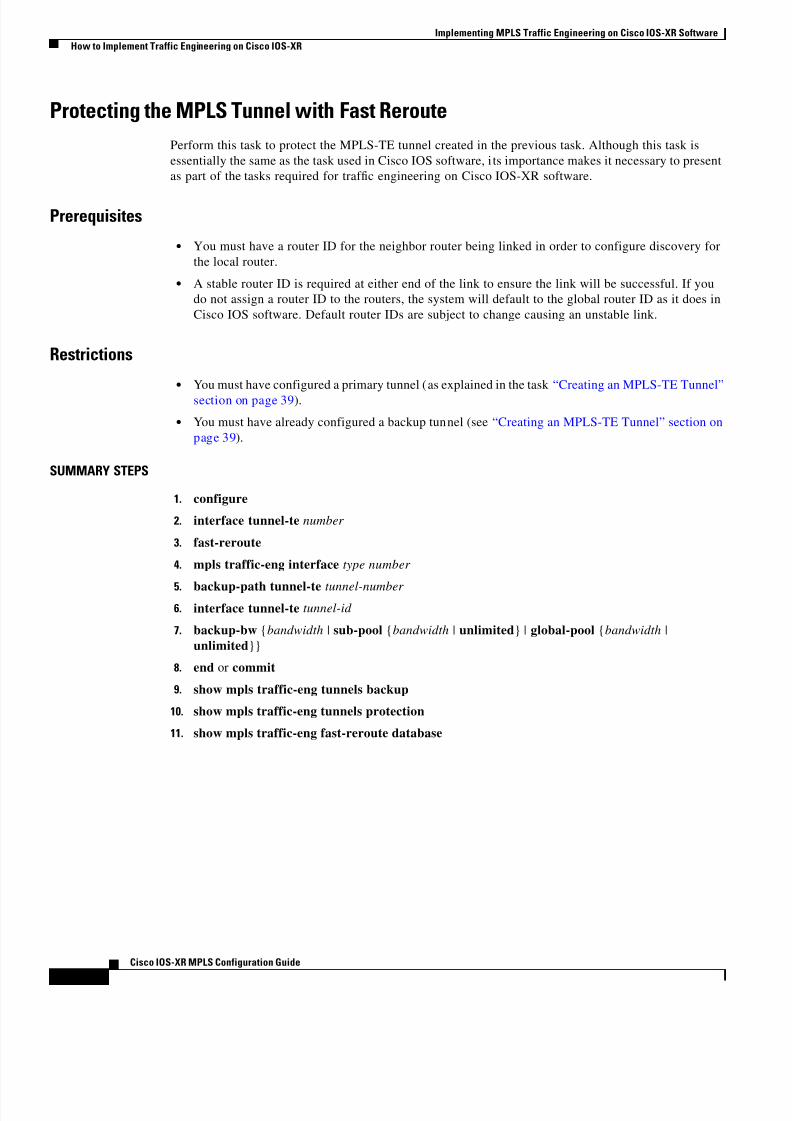
8/11/2019 MPLS Configuration
http://slidepdf.com/reader/full/mpls-configuration 50/98
Implementing MPLS Traffic Engineering on Cisco IOS-XR Software
How to Implement Traffic Engineering on Cisco IOS-XR
MPC-44
Cisco IOS-XR MPLS Configuration Guide
Protecting the MPLS Tunnel with Fast Reroute
Perform this task to protect the MPLS-TE tunnel created in the previous task. Although this task is
essentially the same as the task used in Cisco IOS software, i ts importance makes it necessary to present
as part of the tasks required for traffic engineering on Cisco IOS-XR software.
Prerequisites
• You must have a router ID for the neighbor router being linked in order to configure discovery for
the local router.
• A stable router ID is required at either end of the link to ensure the link will be successful. If you
do not assign a router ID to the routers, the system will default to the global router ID as it does in
Cisco IOS software. Default router IDs are subject to change causing an unstable link.
Restrictions
• You must have configured a primary tunnel (as explained in the task “Creating an MPLS-TE Tunnel”
section on page 39).
• You must have already configured a backup tunnel (see “Creating an MPLS-TE Tunnel” section on
page 39).
SUMMARY STEPS
1. configure
2. interface tunnel-te number
3. fast-reroute
4. mpls traffic-eng interface type number
5. backup-path tunnel-te tunnel-number 6. interface tunnel-te tunnel-id
7. backup-bw {bandwidth | sub-pool {bandwidth | unlimited} | global-pool {bandwidth |
unlimited}}
8. end or commit
9. show mpls traffic-eng tunnels backup
10. show mpls traffic-eng tunnels protection
11. show mpls traffic-eng fast-reroute database

8/11/2019 MPLS Configuration
http://slidepdf.com/reader/full/mpls-configuration 51/98
Implementing MPLS Traffic Engineering on Cisco IOS-XR Software
How to Implement Traffic Engineering on Cisco IOS-XR
MPC-45
Cisco IOS-XR MPLS Configuration Guide
DETAILED STEPS
Command or Action Purpose
Step 1 configure
Example:RP/0/RP0/CPU0:router# configure
Enters the configuration mode.
Step 2 interface tunnel-te number
Example:RP/0/RP0/CPU0:router(config)# interfacetunnel-te1
Enters the MPLS traffic-engineering tunnel interface mode.
In this case, on tunnel TE interface 1.
Step 3 fast-reroute
Example:
RP/0/RP0/CPU0:router(config-if)# fast-reroute
Enables fast reroute.
Step 4 mpls traffic-eng interface type number
Example:RP/0/RP0/CPU0:router(config)# mpls traffic-eng
interface pos0/6/0/0
Enters the MPLS traffic-engineering configuration mode,
and enables traffic engineering on a particular interface on
the originating node. In this case, on pos interface 0/6/0/0.
Step 5 backup-path tunnel-te tunnel-number
Example:RP/0/RP0/CPU0:router(mpls-te-config)# backup-path tunnel-te 2
Sets the backup path to the backup tunnel to ensure that the
backup tunnel outgoing interface is different than POS
interface 0/6/0/0 (for which protection is required).
Step 6 interface tunnel-te tunnel-id
Example:RP/0/RP0/CPU0:router(config)# interfacetunnel-te2
Enters the MPLS traffic-engineering tunnel interface mode.
In this case, on tunnel TE interface 2 (backup tunnel).
Step 7 backup-bw {bandwidth | sub-pool {bandwidth |
unlimited} | global-pool {bandwidth |
unlimited}}
Example:RP/0/RP0/CPU0:router(config-if)# backup-bw
global-pool 5000
Configures backup limited bandwidth of 5000 kbps to
enable bandwidth protection.

8/11/2019 MPLS Configuration
http://slidepdf.com/reader/full/mpls-configuration 52/98
Implementing MPLS Traffic Engineering on Cisco IOS-XR Software
How to Implement Traffic Engineering on Cisco IOS-XR
MPC-46
Cisco IOS-XR MPLS Configuration Guide
Creating a Diff-Serv (Differentiated Services) TE Tunnel
Perform this task to create a differentiated services traffic engineering tunnel.
Prerequisites
• You must have a router ID for the neighbor router being linked in order to configure discovery for
the local router.
• A stable router ID is required at either end of the link to ensure the link will be successful. If you
do not assign a router ID to the routers, the system will default to the global router ID as it does in
Cisco IOS software. Default router IDs are subject to change causing an unstable link.
Step 8 end
or
commit
Example:RP/0/RP0/CPU0:router(config-if)# end
or
RP/0/RP0/CPU0:router(config-if)# commit
Saves configuration changes.
• When you enter the end command, the system prompts
you to commit changes:
Uncommitted changes found. Commit them?
– Entering yes saves configuration changes to the
running configuration file, exits the configuration
session, and returns the router to EXEC mode.
– Entering no exits the configuration session and
returns the router to EXEC mode without
committing the configuration changes.
• When you enter the commit command, the system
saves the configuration changes to the running
configuration file and remains within the configuration
session.
Step 9 show mpls traffic-eng tunnels backup
Example:RP/0/RP0/CPU0:router# show mpls traffic-eng
tunnels backup
(Optional) Displays the backup tunnel information.
Step 10 show mpls traffic-eng tunnels protection
Example:RP/0/RP0/CPU0:router# show mpls traffic-eng
tunnels protection
(Optional) Displays the tunnel protection information.
Step 11 show mpls traffic-eng fast-reroute database
Example:RP/0/RP0/CPU0:router# show mpls traffic-eng
fast-reroute database
(Optional) Displays the protected tunnel state; for instance,
it displays the tunnel’s current ready or active state.
Command or Action Purpose

8/11/2019 MPLS Configuration
http://slidepdf.com/reader/full/mpls-configuration 53/98
Implementing MPLS Traffic Engineering on Cisco IOS-XR Software
How to Implement Traffic Engineering on Cisco IOS-XR
MPC-47
Cisco IOS-XR MPLS Configuration Guide
SUMMARY STEPS
1. configure
2. rsvp
3. interface type number
4. bandwidth total-bandwidth max-flow sub-pool sub-pool-bw
5. interface tunnel-te tunnel-id
6. bandwidth {bandwidth | sub-pool bandwidth}
7. end or commit
DETAILED STEPS
Command or Action Purpose
Step 1 configure
Example:RP/0/RP0/CPU0:router# configure
Enters the configuration mode.
Step 2 rsvp
Example:RP/0/RP0/CPU0:router(config)# rsvp
Enters RSVP configuration mode.
Step 3 interface type number
Example:RP/0/RP0/CPU0:router(config-rsvp)# interface
pos0/6/0/0
Selects the RSVP interface.
Step 4 bandwidth total-bandwidth max-flow sub-pool sub-pool-bw
Example:RP/0/RP0/CPU0:router(config-rsvp-if)# bandwidth 100 150 sub-pool 50
Sets the global maximum RSVP, and sub-pool bandwidth
available on this interface.
Step 5 interface tunnel-te tunnel-id
Example:RP/0/RP0/CPU0:router(config-rsvp-if)# interfacetunnel-te 1
Enters the MPLS traffic-engineering tunnel interface mode.
In this case, on tunnel TE interface 1.

8/11/2019 MPLS Configuration
http://slidepdf.com/reader/full/mpls-configuration 54/98
Implementing MPLS Traffic Engineering on Cisco IOS-XR Software
Configuration Examples for Cisco MPLS Traffic Engineering
MPC-48
Cisco IOS-XR MPLS Configuration Guide
Configuration Examples for Cisco MPLS Traffic EngineeringThis section provides the following examples:
• Configuring Fast Reroute and SONET APS: Example, page MPC-48
• Building MPLS-TE Topology and Tunnels: Example, page MPC-49
Configuring Fast Reroute and SONET APS: Example
When SONET Automatic Protection Switching (APS) is configured on a router, it does not offer
protection for tunnels; because of this limitation, fast reroute (FRR) still remains the protection
mechanism for MPLS traffic-engineering.
When APS is configured in a SONET core network, an alarm might be generated toward a router
downstream. If this router is configured with FRR, the hold-off timer must be configured at the SONET
level in order to prevent FRR from being triggered while the core network is performing a restoration.
Enter the following commands to configure the delay:
RP/0/RP0/CPU0:Route-3(config)# controller sonet 0/6/0/0 delay trigger line 250
RP/0/RP0/CPU0:Route-3(config)# controller sonet 0/6/0/0 path delay trigger 300
Step 6 bandwidth {bandwidth | sub-pool bandwidth}
Example:RP/0/RP0/CPU0:router(mpls-if)# bandwidth
sub-pool 10
Sets the subpool bandwidth available on this interface.
Step 7 end
or
commit
Example:RP/0/RP0/CPU0:router(mpls-if)# end
or
RP/0/RP0/CPU0:router(mpls-if)# commit
Saves configuration changes.
• When you enter the end command, the system prompts
you to commit changes:
Uncommitted changes found. Commit them?
– Entering yes saves configuration changes to the
running configuration file, exits the configuration
session, and returns the router to EXEC mode.
– Entering no exits the configuration session and
returns the router to EXEC mode without
committing the configuration changes.
• When you enter the commit command, the system
saves the configuration changes to the running
configuration file and remains within the configuration
session.
Command or Action Purpose

8/11/2019 MPLS Configuration
http://slidepdf.com/reader/full/mpls-configuration 55/98
Implementing MPLS Traffic Engineering on Cisco IOS-XR Software
Configuration Examples for Cisco MPLS Traffic Engineering
MPC-49
Cisco IOS-XR MPLS Configuration Guide
Building MPLS-TE Topology and Tunnels: Example
The following example shows how to build a topology and a tunnel:
configure
mpls traffic-eng interface pos 0/6/0/0
router id loopback 0 router ospf 1
router-id 192.168.25.66 area 0
interface pos 0/6/0/0
interface loopback 0
mpls traffic-eng loopback 0 mpls traffic-eng area 0
rsvp pos 0/6/0/0
bandwidth 100
commit
show mpls traffic-eng topologyshow mpls traffic-eng link-management advertisement
!interface tunnel-te 1
tunnel destination 192.168.92.125
ipv4 unnumbered loopback 0
path-option l dynamic bandwidth 100
commit
show mpls traffic-eng tunnels
show ipv4 interface brief
show mpls traffic-eng link-management admission-control!
interface tunnel-te1
ipv4 unnumbered loopback 0
autoroute announce route ipv4 192.168.12.52/32 tunnel-te1
commitping 192.168.12.52
show mpls traffic autoroute
!
interface tunnel-te1 fast-reroute
mpls traffic-eng interface pos 0/6/0/0 backup-path tunnel-te 2
interface tunnel-te2
backup-bw global-pool 5000
commitshow mpls traffic-eng tunnels backup
!rsvp
interface pos 0/6/0/0
bandwidth 100 150 sub-pool 50 interface tunnel-te1
bandwidth sub-pool 10commit

8/11/2019 MPLS Configuration
http://slidepdf.com/reader/full/mpls-configuration 56/98
Implementing MPLS Traffic Engineering on Cisco IOS-XR Software
Additional References
MPC-50
Cisco IOS-XR MPLS Configuration Guide
Additional ReferencesFor additional information related to implementing traffic engineering, refer to the following references:
Related Documents
Standards
MIBs
RFCs
Related Topic Document Title
Cisco IOS-XR MPLS RSVP commands RSVP Infrastructure Commands on Cisco IOS-XR Software
Cisco IOS-XR LDP commands MPLS Label Distribution Protocol Commands on Cisco IOS-XR
Software
Cisco IOS-XR O-UNI commands MPLS Optical User Network Interface Commands on Cisco IOS-XR
Software
Cisco IOS-XR MPLS-TE commands MPLS Traffic Engineering Commands on Cisco IOS-XR Software
Cisco IOS MPLS overview guide Multiprotocol Label Switching Overview
Cisco IOS MPLS configuration guide Configuring Multiprotocol Label Switching
Standards Title
No new or modified standards are supported by the
features in this document, and support for existing
standards had not been modified by the features in this
document.
—
MIBs MIBs Link
None To locate and download MIBs for selected platforms, Cisco IOS
releases, and feature sets, use Cisco MIB Locator found at the
following URL:
http://www.cisco.com/go/mibs
RFCs Title
No new or modified RFCs are supported by this
feature, and support for existing RFCs has not been
modified by this feature.

8/11/2019 MPLS Configuration
http://slidepdf.com/reader/full/mpls-configuration 57/98
Implementing MPLS Traffic Engineering on Cisco IOS-XR Software
Additional References
MPC-51
Cisco IOS-XR MPLS Configuration Guide
Technical Assistance
Description Link
Technical Assistance Center (TAC) home page,
containing 30,000 pages of searchable technical
content, including links to products, technologies,solutions, technical tips, and tools. Registered
Cisco.com users can log in from this page to access
even more content.
http://www.cisco.com/public/support/tac/home.shtml

8/11/2019 MPLS Configuration
http://slidepdf.com/reader/full/mpls-configuration 58/98
Implementing MPLS Traffic Engineering on Cisco IOS-XR Software
Glossary
MPC-52
Cisco IOS-XR MPLS Configuration Guide
GlossaryAAA—authentication, authorization, and accounting.
CoS—class of service. An indication of how an upper-layer protocol requires a lower-layer protocol to
treat its messages. In SNA subarea routing, CoS definitions are used by subarea nodes to determine the
optimal route to establish a given session. A CoS definition comprises a virtual route number and a
transmission priority field.
CSPF—Constrained Shortest Path First. A routing algorithm used in MPLS-TE.
DS-TE—Diff-Serv aware traffic engineering feature that supports different bandwidth constraints for
different traffic classes using Diff-Serv model with bandwidth pools. In combination with other features,
this may be used to achieve MPLS Guaranteed Bandwidth services.
DWDM—Dense Wave Division Multiplexing.
ERO—Explicit Route Object. One of the fields in RSVP messages. It specifies the route that the RSVP
tunnel should take.
FCAPS—Fault, configuration, accounting, performance, and security.
FIB—Forwarding Information Base. Table that is used on the line card to prepare the packet forforwarding.
FRR—fast reroute.
Generalized MPLS—Extensions to the protocols used for control of MPLS-TE LSPs, which support
the use of a variety of switching techniques.
GMPLS-TE—Generalized MPLS Traffic Engineering.
GR—Graceful Restart.
HA—High Availability.
ICMP—Internet Control Message Protocol.
IGP—Interior Gateway Protocol. A class of routing protocol.
IPCC—IP Control Channel.
IS-IS—Intermediate System-to-Intermediate System. An IGP protocol.
LM—link manager.
LSA—link-state advertisement. Broadcast packet used by link-state protocols that contains information
about neighbors and path costs. LSAs are used by the receiving routers to maintain their routing tables.
LSD—label switching database.
LSP—label switched path. a sequence of hops along which packets are forwarded using MPLS
mechanisms. Dynamic label switched paths are typically used to forward packets across networks using
labels advertised via LDP for routing prefixes. Static LSPs are typically used to forward packets along
traffic engineered paths.
LSP Tunnel / MPLS TE Tunnel—A tunnel that uses static LSPs to forward packets to the destination.
This phrase is often used in the abstract sense, with emphasis on the fact that the tunnel is using an LSP
to forward data, but without emphasis on the implementation of the tunnel itself.
LSR—label switch router. The role of an LSR is to forward packets in an MPLS network by looking
only at the fixed-length label.
MIB—Management Information Base. Database of network management information that is used and
maintained by a network management protocol, such as SNMP or CMIP.

8/11/2019 MPLS Configuration
http://slidepdf.com/reader/full/mpls-configuration 59/98
Implementing MPLS Traffic Engineering on Cisco IOS-XR Software
Glossary
MPC-53
Cisco IOS-XR MPLS Configuration Guide
MP—merge point (in fast rerouting).
MPLS—Multiprotocol Label Switching. Switching method that forwards IP traffic using a label. This
label instructs the routers and the switches in the network where to forward the packets based on
preestablished IP routing information.
MPlS—Multiprotocol lambda switching. Also known as Generalized MPLS.
MPLS-TE—MPLS traffic engineering.
NSF—Non-stop forwarding. Generic table mechanism in which the goal is to have continuous packet
forwarding despite failures in the system control plane (routing protocols and others).
QoS—quality of service.
RIB—Routing Information Base.
RP—Route Processor. In a distributed system, the RP is where all the routing protocol processes run.
RSVP—Resource Reservation Protocol. Protocol that supports the reservation of resources across an IP
network. Applications running on IP end systems can use RSVP to indicate to other nodes the nature
(bandwidth, jitter, maximum burst, and so on) of the packet streams they want to receive. RSVP depends
on IPv6.
TE—traffic engineering. Mechanisms used to cause certain data packets to follow a predetermined path
through the network, other than that which the IGP specifies as being the current shortest path.
TED—traffic engineering database.
VRF—VPN routing/forwarding instance.
Note Refer to the Internetworking Terms and Acronyms for terms not included in this glossary.

8/11/2019 MPLS Configuration
http://slidepdf.com/reader/full/mpls-configuration 60/98
Implementing MPLS Traffic Engineering on Cisco IOS-XR Software
Glossary
MPC-54
Cisco IOS-XR MPLS Configuration Guide

8/11/2019 MPLS Configuration
http://slidepdf.com/reader/full/mpls-configuration 61/98
Corporate Headquarters:
Copyright © 2004 Cisco Systems, Inc. All rights reserved.
Cisco Systems, Inc., 170 West Tasman Drive, San Jose, CA 95134-1706 USA
Implementing MPLS Forwarding onCisco IOS-XR Software
Comparison of Cisco IOS MPLS Forwarding and Cisco IOS-XR
MPLS ForwardingThe Multiprotocol Label Switching (MPLS) Forwarding feature in Cisco IOS-XR software functions the
same as it does in Cisco IOS software.
All MPLS features require a core set of MPLS label management and forwarding services; the MPLS
Forwarding Infrastructure (MFI) supplies these services.
MPLS combines the performance and capabilities of Layer 2 (data link layer) switching with the proven
scalability of Layer 3 (network layer) routing. MPLS enables service providers to meet the challenges
of growth in network utilization while providing the opportunity to differentiate services without
sacrificing the existing network infrastructure. The MPLS architecture is flexible and can be employed
in any combination of Layer 2 technologies. MPLS support is offered for all Layer 3 protocols, and
scaling is possible well beyond that typically offered in today’s networks.
MFI Control Plane Services
The MFI control plane provides services to MPLS applications, such as Label Distribution Protocol
(LDP) and Traffic Engineering (TE), that include enabling and disabling MPLS on an interface, local
label allocation, MPLS rewrite setup (including backup links), management of MPLS label tables, and
the interaction with other forwarding paths (IPv4 for example) to set up imposition and disposition.
MFI Data Plane Services
The MFI data plane provides a software implementation of MPLS forwarding in all of its forms:imposition, disposition, and label swapping.

8/11/2019 MPLS Configuration
http://slidepdf.com/reader/full/mpls-configuration 62/98
Implementing MPLS Forwarding on Cisco IOS-XR Software
Comparison of Cisco IOS MPLS Forwarding and Cisco IOS-XR MPLS Forwarding
MPC-56
Cisco IOS-XR MPLS Configuration Guide
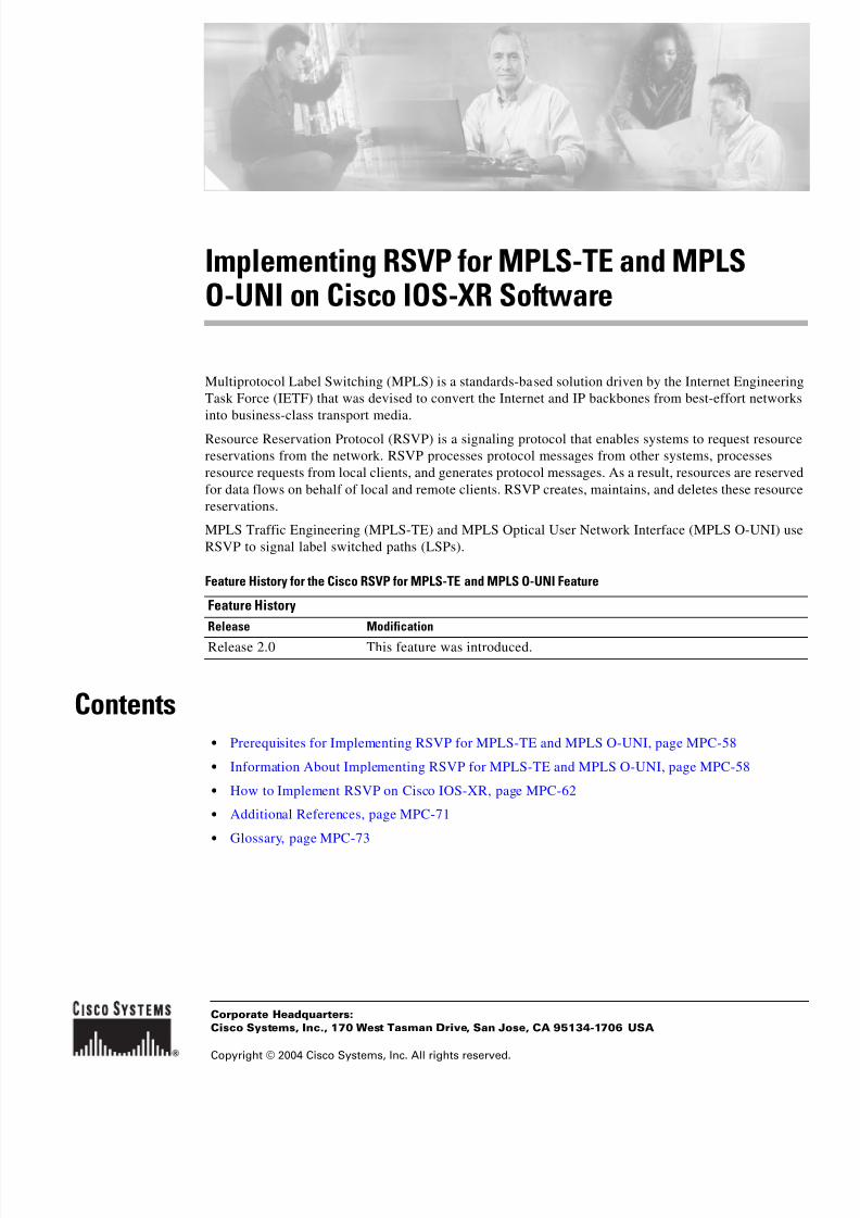
8/11/2019 MPLS Configuration
http://slidepdf.com/reader/full/mpls-configuration 63/98
Corporate Headquarters:
Copyright © 2004 Cisco Systems, Inc. All rights reserved.
Cisco Systems, Inc., 170 West Tasman Drive, San Jose, CA 95134-1706 USA
Implementing RSVP for MPLS-TE and MPLSO-UNI on Cisco IOS-XR Software
Multiprotocol Label Switching (MPLS) is a standards-based solution driven by the Internet Engineering
Task Force (IETF) that was devised to convert the Internet and IP backbones from best-effort networks
into business-class transport media.
Resource Reservation Protocol (RSVP) is a signaling protocol that enables systems to request resource
reservations from the network. RSVP processes protocol messages from other systems, processes
resource requests from local clients, and generates protocol messages. As a result, resources are reserved
for data flows on behalf of local and remote clients. RSVP creates, maintains, and deletes these resource
reservations.
MPLS Traffic Engineering (MPLS-TE) and MPLS Optical User Network Interface (MPLS O-UNI) use
RSVP to signal label switched paths (LSPs).
Feature History for the Cisco RSVP for MPLS-TE and MPLS O-UNI Feature
Contents• Prerequisites for Implementing RSVP for MPLS-TE and MPLS O-UNI, page MPC-58
• Information About Implementing RSVP for MPLS-TE and MPLS O-UNI, page MPC-58
• How to Implement RSVP on Cisco IOS-XR, page MPC-62
• Additional References, page MPC-71
• Glossary, page MPC-73
Feature History
Release Modification
Release 2.0 This feature was introduced.

8/11/2019 MPLS Configuration
http://slidepdf.com/reader/full/mpls-configuration 64/98
Implementing RSVP for MPLS-TE and MPLS O-UNI on Cisco IOS-XR Software
Prerequisites for Implementing RSVP for MPLS-TE and MPLS O-UNI
MPC-58
Cisco IOS-XR MPLS Configuration Guide
Prerequisites for Implementing RSVP for MPLS-TE and MPLSO-UNI
The following are prerequisites for implementing RSVP for MPLS-TE and MPLS O-UNI on the router:
• Either a composite mini-image plus a MPLS package, or a full image, must be installed.
• You must be a member of a user group associated with the MPLS-TE and O-UNI task IDs.
Information About Implementing RSVP for MPLS-TE and MPLSO-UNI
To implement MPLS RSVP on Cisco IOS-XR software, you must understand the following concepts:
• Comparison of Cisco IOS RSVP and Cisco IOS-XR RSVP, page MPC-58
• Overview of RSVP for MPLS-TE and MPLS O-UNI, page MPC-58
• LSP Setup, page MPC-59
• High Availability, page MPC-60
• Graceful Restart, page MPC-60
• Differential Service Tunnels, page MPC-62
Comparison of Cisco IOS RSVP and Cisco IOS-XR RSVP
• Cisco IOS-XR RSVP uses a protocol-based command line interface (CLI) (instead of
interface-based CLI as in Cisco IOS software).
• Cisco IOS-XR RSVP CLI (config, show, and debug) accepts rsvp as well as ip rsvp. The ip rsvp version of the commands is hidden.
• Cisco IOS-XR RSVP uses a default refresh interval of 45 seconds (instead of 30 seconds as in Cisco
IOS software).
• In Cisco IOS-XR software, all the refresh configuration is per-interface, whereas in Cisco IOS
software it is global.
Overview of RSVP for MPLS-TE and MPLS O-UNI
RSVP is a network-control protocol that enables Internet applications to signal LSPs for MPLS-TE, and
LSPs for O-UNI. The RSVP implementation is compliant with the IETF RFC 2205, RFC 3209, and
OIF2000.125.7.
When configuring an O-UNI LSP, the RSVP session is bidirectional. The exchange of data between a
pair of machines actually constitutes a single RSVP session. The RSVP session is established using an
Out-Of-Band (OOB) IP Control Channel (IPCC) with the neighbor. The RSVP messages are transported
over an interface other than the data interface.

8/11/2019 MPLS Configuration
http://slidepdf.com/reader/full/mpls-configuration 65/98
Implementing RSVP for MPLS-TE and MPLS O-UNI on Cisco IOS-XR Software
Information About Implementing RSVP for MPLS-TE and MPLS O-UNI
MPC-59
Cisco IOS-XR MPLS Configuration Guide
RSVP supports extensions according to OIF2000.125.7 requirements such as:
• Generalized Label Request
• Generalized UNI Attribute
• UNI Session
• New Error Spec sub-codes
RSVP is automatically enabled on interfaces on which MPLS-TE is configured. For MPLS-TE LSPs
with non-zero bandwidth, the RSVP bandwidth has to be configured on the interfaces. There is no need
to configure RSVP, if all MPLS-TE LSPs have zero bandwidth. For O-UNI, there is no need for any
RSVP configuration.
RSVP Refresh Reduction, defined in RFC2961, includes support for reliable messages and summary
refresh messages. Reliable messages are retransmitted rapidly if the message is lost. Because each
summary refresh message contains information to refresh multiple states, this greatly reduces the
amount of messaging needed to refresh states. For refresh reduction to be used between two routers, it
must be enabled on both routers. Refresh Reduction is enabled by default.
Message rate limiting for RSVP allows you to set a maximum threshold on the rate at which RSVP
messages are sent on an interface. Message rate limiting is disabled by default.
The process that implements RSVP is restartable. A software upgrade, process placement or process
failure of RSVP or any of its collaborators, has been designed to ensure Nonstop Forwarding (NSF) of
the data plane.
RSVP supports graceful restart, which is compliant with RFC 3473. It follows the procedures that apply
when the node reestablishes communication with the neighbor’s control plane within a configured restart
time.
It is important to note that RSVP is not a routing protocol. RSVP works in conjunction with routing
protocols and installs the equivalent of dynamic access lists along the routes that routing protocols
calculate. Because of this, implementing RSVP in an existing network does not require migration to a
new routing protocol.
LSP Setup
LSP setup is initiated when the LSP head node sends path messages to the tail node. (See Figure 6.)
Figure 6 RSVP Operation
9 5 1 3 5
R1
In Out
IP route 17
R2 R3 R4
Path
Ingress routing table
RESV
Label = 17
IngressLSR
EgressLSRPath
RESV
Label = 20
Path
RESV
Label = 3
In Out
17 20
MPLS table
In Out
20 3
MPLS table
In Out
3 IP route
Egress routing table

8/11/2019 MPLS Configuration
http://slidepdf.com/reader/full/mpls-configuration 66/98
Implementing RSVP for MPLS-TE and MPLS O-UNI on Cisco IOS-XR Software
Information About Implementing RSVP for MPLS-TE and MPLS O-UNI
MPC-60
Cisco IOS-XR MPLS Configuration Guide
The Path messages reserve resources along the path to each node, creating Path soft states on each node.
When the tail node receives a path message, it sends a reservation (RESV) message with a label back to
the previous node. When the reservation message arrives at the previous node, it causes the reserved
resources to be locked and forwarding entries are programmed with the MPLS label sent from the
tail-end node. A new MPLS label is allocated and sent to the next node upstream.
When the reservation message reaches the head node, the label is programmed and the MPLS data startsto flow along the path.
The above example illustrates an LSP setup for non-O-UNI applications. In the case of an O-UNI
application, the RSVP signaling messages are exchanged on a control channel, and the corresponding
data channel to be used is acquired from the LMP Manager module based on the control channel. Also
the O-UNI LSP’s are by default bidirectional while the MPLS-TE LSP’s are uni-directional.
High Availability
RSVP has been designed to ensure nonstop forwarding under the following constraints:
• Ability to tolerate the failure of one or more MPLS/O-UNI processes.
• Ability to tolerate the failure of one RP of a 1:1 redundant pair.
• Hitless software upgrade.
The RSVP high availability (HA) design follows the constraints of the underlying architecture where
processes can fail without affecting the operation of other processes. A process failure of RSVP or any
of its collaborators does not cause any traffic loss or cause established LSPs to go down. When RSVP
restarts, it recovers its signaling states from its neighbors. No special configuration or manual
intervention are required. You may configure RSVP graceful restart, which offers a standard mechanism
to recover RSVP state information from neighbors after a failure.
Graceful Restart
RSVP graceful restart provides a control plane mechanism to ensure high availability, which allows
detection and recovery from failure conditions while preserving nonstop forwarding services on the
systems running Cisco IOS-XR software.
RSVP graceful restart provides a mechanism that minimizes the negative effects on MPLS O-UNI traffic
caused by the following types of faults:
• Disruption of communication channels between two nodes when the communication channels are
separate from the data channels. This is called control channel failure.
• The control plane of a node fails but the node preserves its data forwarding states. This is called node
failure.
The procedure for RSVP graceful restart is described in the “Fault Handling” section of RFC 3473:
Generalized MPLS Signaling, RSVP-TE Extensions. One of the main advantages of using RSVP gracefulrestart is recovery of the control plane while preserving nonstop forwarding and existing labels. RSVP
graceful restart is configured globally on the router. Figure 7 illustrates how RSVP graceful restart
handles a node failure condition.

8/11/2019 MPLS Configuration
http://slidepdf.com/reader/full/mpls-configuration 67/98
Implementing RSVP for MPLS-TE and MPLS O-UNI on Cisco IOS-XR Software
Information About Implementing RSVP for MPLS-TE and MPLS O-UNI
MPC-61
Cisco IOS-XR MPLS Configuration Guide
Figure 7 Node Failure with RSVP
RSVP graceful restart requires the use of RSVP hello messages. Hello messages are used between RSVP
neighbors. Each neighbor can autonomously issue a hello message containing a hello request object. A
receiver that supports the hello extension replies with a hello message containing a hello
acknowledgement (ACK) object. This means that a hello message contains either a hello Request or ahello ACK object. These two objects have the same format.
The restart cap object indicates a node’s restart capabilities. It is carried in hello messages if the sending
node supports state recovery. The restart cap object has the following two fields:
• Restart Time: This is the amount of time after a control-plane restart (on the sender node) within
which RSVP can start exchanging hello messages. It is possible for a user to manually configure the
Restart Time.
• Recovery Time: This is the amount of time that the sender waits for the recipient to re-synchronize
states after the re-establishment of hello messages. This value is computed and advertised based on
number of states that existed before the fault occurred.
For graceful restart, the hello messages are sent with an IP Time to Live (TTL) of 64. This is because
the destination of the hello messages can be multiple hops away. If graceful restart is enabled, hellomessages (containing the restart cap object) are send to an RSVP neighbor when RSVP states are shared
with that neighbor.
Restart cap objects are sent to an RSVP neighbor when RSVP states are shared with that neighbor. If the
neighbor replies with hello messages containing the restart cap object, then the neighbor is considered
to be graceful restart capable. If the neighbor does not reply with hello messages or replies with hello
messages that do not contain the restart cap object, RSVP backs off sending hellos to that neighbor. If
graceful restart is disabled, no hello messages (Requests or ACKs) are sent. If a hello Request message
is received from an unknown neighbor, no hello ACK is sent back.
9 5 1 3 3
XRSVP Hellos stopped
RSVP Hellos resume
RSVP Hellos being exchanged
SI = 0x23da459f DI = 0x12df3487Restart Time = 60 sec.Recovery Time = 160 sec.
Different SI values
indicate a node failure
SI = 0x12df3487 DI = 0x23da459fRestart Time = 90 sec.Recovery Time = 0
Missed HellosMust wait 60 secpreserve states
SI = 0x12df3487 DI = 0xaa236dcRestart Time = 90 sec.Recovery Time = 0
Must refresh (use pacing)
all states in ½ recoveryperiod = 80 sec.
X Y
X Y
Nodefailure
SI = 0x12df3487 DI = 0xaa236dcRestart Time = 90 sec.
Recovery Time = 0
SI = 0xaa236dc DI = 0x12df3487Restart Time = 60 sec.
Recovery Time = 0

8/11/2019 MPLS Configuration
http://slidepdf.com/reader/full/mpls-configuration 68/98
Implementing RSVP for MPLS-TE and MPLS O-UNI on Cisco IOS-XR Software
How to Implement RSVP on Cisco IOS-XR
MPC-62
Cisco IOS-XR MPLS Configuration Guide
Differential Service Tunnels
Differential Service Traffic Engineering (TE) is an extension of the regular MPLS Traffic Engineering
(MPLS-TE) feature. Regular TE does not provide bandwidth guarantees to different traffic classes. A
single bandwidth pool (global pool) is used in regular TE that is shared by all traffic. In order to support
various class of service (CoS), the ability to provide multiple bandwidth pools is required. Thesebandwidth pools then can be treated differently based on the requirement for the traffic class using that
pool.
In RSVP global and subpools reservable bandwidths are configured on a per interface basis to
accommodate TE tunnels on the node. Available bandwidth from all configured bandwidth pools is
advertised using Interior Gateway Protocol (IGP). RSVP is used to signal the TE tunnel with appropriate
bandwidth pool requirements.
How to Implement RSVP on Cisco IOS-XRRSVP requires coordination among several routers, establishing exchange of RSVP messages to setup
LSPs. Depending on the client application, RSVP requires some basic configuration.
• Configuring Traffic Engineering Tunnel Bandwidth, page MPC-62
• Confirming DiffServ TE Bandwidth, page MPC-63
• Configuring MPLS O-UNI Bandwidth, page MPC-65
• Enabling Graceful Restart, page MPC-65
• Verifying RSVP Configuration, page MPC-66
Configuring Traffic Engineering Tunnel Bandwidth
For TE tunnel setup, you must configure the bandwidth to be set aside per interface. When no RSVPbandwidth is specified for a particular interface, you can specify zero bandwidth in the LSP setup if it is
configured under RSVP interface configuration mode or MPLS-TE configuration mode.
SUMMARY STEPS
1. configure
2. rsvp
3. interface interface-name
4. bandwidth total-bandwidth max-flow sub-pool sub-pool-bw
5. end or commit

8/11/2019 MPLS Configuration
http://slidepdf.com/reader/full/mpls-configuration 69/98
Implementing RSVP for MPLS-TE and MPLS O-UNI on Cisco IOS-XR Software
How to Implement RSVP on Cisco IOS-XR
MPC-63
Cisco IOS-XR MPLS Configuration Guide
DETAILED STEPS
Confirming DiffServ TE BandwidthPerform this task to confirm DiffServ TE bandwidth. In RSVP global and subpool(s), reservable
bandwidths are configured per interface to accommodate TE tunnels on the node. Available bandwidth
from all configured bandwidth pools is advertised using IGP. RSVP is used to signal the TE tunnel with
appropriate bandwidth pool requirements.
Command or Action Purpose
Step 1 configure
Example:RP/0/0/1:router# configure
Enters global configuration mode.
Step 2 rsvp
Example:RP/0/0/1:router(config)# rsvp
Enters RSVP configuration mode.
Step 3 interface interface-name
Example:RP/0/0/1:router(config-rsvp)# interface pos
0/2/0/0
Selects the RSVP interface.
Step 4 bandwidth total-bandwidth max-flow sub-pool
sub-pool-bw
Example:RP/0/0/1:router(config-rsvp-if)# bandwidth 1000150
Sets the reservable bandwidth and maximum RSVP
bandwidth available for a flow on this interface.
Step 5 end
or
commit
Example:
RP/0/0/1:router(config-rsvp-if)# endor
RP/0/0/1:router(config-rsvp-if)# commit
Saves configuration changes.
• When you enter the end command, the system prompts
you to commit changes:
Uncommitted changes found. Commit them?
– Entering yes saves configuration changes to the
running configuration file, exits the configuration
session, and returns the router to EXEC mode.
– Entering no exits the configuration session and
returns the router to EXEC mode without
committing the configuration changes.
• When you enter the commit command, the system
saves the configuration changes to the running
configuration file and remains within the configuration
session.

8/11/2019 MPLS Configuration
http://slidepdf.com/reader/full/mpls-configuration 70/98
Implementing RSVP for MPLS-TE and MPLS O-UNI on Cisco IOS-XR Software
How to Implement RSVP on Cisco IOS-XR
MPC-64
Cisco IOS-XR MPLS Configuration Guide
SUMMARY STEPS
1. configure
2. rsvp
3. interface interface-name
4. bandwidth total-bandwidth max-flow sub-pool sub-pool-bw
5. end or commit
DETAILED STEPS
Command or Action Purpose
Step 1 configure
Example:RP/0/0/1:router# configure
Enters global configuration mode.
Step 2 rsvp
Example:RP/0/0/1:router(config)# rsvp
Enters RSVP configuration mode.
Step 3 interface interface-name
Example:RP/0/0/1:router(config-rsvp)# interface pos
0/2/0/0
Selects the RSVP interface.
Step 4 bandwidth total-bandwidth max-flow sub-pool
sub-pool-bw
Example:RP/0/0/1:router(config-rsvp-if)# bandwidth 1000
100 sub-pool 150
Sets the reservable bandwidth, the maximum RSVP
bandwidth available for a flow and the subpool bandwidth
on this interface.
Step 5 end
or
commit
Example:RP/0/0/1:router(config-rsvp-if)# end
or
RP/0/0/1:router(config-rsvp-if)# commit
Saves configuration changes.
• When you enter the end command, the system prompts
you to commit changes:
Uncommitted changes found. Commit them?
– Entering yes saves configuration changes to the
running configuration file, exits the configuration
session, and returns the router to EXEC mode.
–
Entering no exits the configuration session andreturns the router to EXEC mode without
committing the configuration changes.
• When you enter the commit command, the system
saves the configuration changes to the running
configuration file and remains within the configuration
session.

8/11/2019 MPLS Configuration
http://slidepdf.com/reader/full/mpls-configuration 71/98
Implementing RSVP for MPLS-TE and MPLS O-UNI on Cisco IOS-XR Software
How to Implement RSVP on Cisco IOS-XR
MPC-65
Cisco IOS-XR MPLS Configuration Guide
Configuring MPLS O-UNI Bandwidth
For this application you do not need to configure bandwidth for the data channel or the control channel.
There is no other specific RSVP configuration needed for this application.
Enabling Graceful Restart
Perform this task to enable graceful restart. RSVP graceful restart provides a control plane mechanism
to ensure high availability, which allows detection and recovery from failure conditions while preserving
nonstop forwarding services on the router.
SUMMARY STEPS
1. configure
2. rsvp
3. signalling graceful-restart
4. end or commit
DETAILED STEPS
Command or Action Purpose
Step 1 configure
Example:RP/0/0/1:Router# configure terminal
Enters global configuration mode
Step 2 rsvp
Example:RP/0/0/1:router(config)# rsvp
Enters the RSVP configuration submode.

8/11/2019 MPLS Configuration
http://slidepdf.com/reader/full/mpls-configuration 72/98
Implementing RSVP for MPLS-TE and MPLS O-UNI on Cisco IOS-XR Software
How to Implement RSVP on Cisco IOS-XR
MPC-66
Cisco IOS-XR MPLS Configuration Guide
Verifying RSVP Configuration
The following is the topology on which this section is based:
Figure 8 Sample Topology
To verify RSVP configuration, perform the following steps.
SUMMARY STEPS
1. show rsvp session
2. show rsvp counters messages summary
3. show rsvp counters events
4. show rsvp interface type number [detail]
5. show rsvp graceful-restart
6. show rsvp graceful-restart [neighbors ip-address | detail]
7. show rsvp interface
Step 3 signalling graceful-restart
Example:RP/0/0/1:router(config-rsvp)# signalling
graceful-restart
Enables the graceful restart process on the node.
Step 4 end
or
commit
Example:RP/0/0/1:router(config-rsvp)# end
or
RP/0/0/1:router(config-rsvp)# commit
Saves configuration changes.
• When you enter the end command, the system prompts
you to commit changes:
Uncommitted changes found. Commit them?
– Entering yes saves configuration changes to the
running configuration file, exits the configuration
session, and returns the router to EXEC mode.
– Entering no exits the configuration session and
returns the router to EXEC mode without
committing the configuration changes.
• When you enter the commit command, the system
saves the configuration changes to the running
configuration file and remains within the configuration
session.
Command or Action Purpose
1 0 3 1 9 4
51.51.51.51 60.60.60.60 70.70.70.70
Router 1
LSP from R1 to R3
Router 2 Router 3

8/11/2019 MPLS Configuration
http://slidepdf.com/reader/full/mpls-configuration 73/98
Implementing RSVP for MPLS-TE and MPLS O-UNI on Cisco IOS-XR Software
How to Implement RSVP on Cisco IOS-XR
MPC-67
Cisco IOS-XR MPLS Configuration Guide
DETAILED STEPS
Step 1 show rsvp session
Use this command to verify that all routers on the path of the LSP are configured with at least one Path
State Block (PSB) and one Reservation State Block (RSB) per session. For example:
RP/0/RP0/CPU0:router# show rsvp session
Type Destination Add DPort Proto/ExtTunID PSBs RSBs Reqs---- --------------- ----- --------------- ----- ----- -----
LSP4 172.16.70.70 6 10.51.51.51 1 1 0
In the example above, the output represents an LSP from ingress (head) router 10.51.51.51 to egress
(tail) router 172.16.70.70. The tunnel ID (a.k.a destination port) is 6.
• If no states can be found for a session that should be up, verify the application (for example,
MPLS-TE and O-UNI) to see if everything is in order.
• If a session has one PSB but no RSB, this indicates that either the Path message is not making it to
the egress (tail) router or the reservation message is not making it back to the router R1 in question
Go to the downstream router R2 and display the session information:
• If R2 has no PSB, then either the path message is not making it to the router or the path message is
being rejected (for example, due to lack of resources).
• If R2 has a PSB but no RSB, go to the next downstream router R3 to investigate.
• If R2 has a PSB and an RSB, this means the reservation is not making it from R2 to R1 or is being
rejected.
Step 2 show rsvp counters messages summary
Use this command to verify whether RSVP message are being transmitted and received. For example:
RP/0/RP0/CPU0:router# show rsvp counters messages summary
All RSVP Interfaces Recv Xmit Recv Xmit Path 0 25 Resv 30 0
PathError 0 0 ResvError 0 1
PathTear 0 30 ResvTear 12 0
ResvConfirm 0 0 Ack 24 37 Bundle 0 Hello 0 5099
SRefresh 8974 9012 OutOfOrder 0Retransmit 20 Rate Limited 0
Step 3 show rsvp counters events
Use this command to see how many RSVP states have expired. Since RSVP uses a soft-state mechanism,
some failures will lead to RSVP states to expire due to lack of refresh from the neighbor. For example:
RP/0/RP0/CPU0:router# show rsvp counters events
mgmtEthernet0/0/0/0 tunnel6Expired Path states 0 Expired Path states 0Expired Resv states 0 Expired Resv states 0
NACKs received 0 NACKs received 0POS0/3/0/0 POS0/3/0/1
Expired Path states 0 Expired Path states 0
Expired Resv states 0 Expired Resv states 0
NACKs received 0 NACKs received 0POS0/3/0/2 POS0/3/0/3
Expired Path states 0 Expired Path states 0Expired Resv states 0 Expired Resv states 1

8/11/2019 MPLS Configuration
http://slidepdf.com/reader/full/mpls-configuration 74/98

8/11/2019 MPLS Configuration
http://slidepdf.com/reader/full/mpls-configuration 75/98
Implementing RSVP for MPLS-TE and MPLS O-UNI on Cisco IOS-XR Software
Configuration Examples for RSVP
MPC-69
Cisco IOS-XR MPLS Configuration Guide
Interface MaxBW MaxFlow Allocated MaxSub
----------- -------- -------- --------------- --------
Et0/0/0/0 0 0 0 ( 0%) 0PO0/3/0/0 1000M 1000M 0 ( 0%) 0
PO0/3/0/1 1000M 1000M 0 ( 0%) 0PO0/3/0/2 1000M 1000M 0 ( 0%) 0
PO0/3/0/3 1000M 1000M 1K ( 0%) 0
Configuration Examples for RSVPThe following section gives sample RSVP configurations for some of the supported RSVP features.
More details on the commands can be found in the Resource Reservation Protocol Infrastructure
Commands guide. Examples are provided for the following features:
• Bandwidth Configuration: Example, page MPC-69
• Refresh Reduction and Reliable Messaging Configuration: Example, page MPC-69
• Configuring Graceful Restart: Example, page MPC-70
• Setting DSCP for RSVP Packets: Example, page MPC-71
Bandwidth Configuration: Example
The following example shows the configuration of bandwidth on an interface that will be used by RSVP.
The example configures an interface for a reservable bandwidth of 7500, specifies the maximum
bandwidth for one flow to be 1000 and adds a subpool bandwidth of 2000:
rsvp interface pos 0/3/0/0 bandwidth 7500 1000 sub-pool 2000
Refresh Reduction and Reliable Messaging Configuration: Example
Refresh reduction feature as defined by RFC 2961 is supported and is enabled on IOS-XR routers by
default in RSVP. The following examples illustrate the configuration for the refresh reduction feature.
Refresh reduction is used with a neighbor only if the neighbor supports it also.
Changing the Refresh Interval and the Number of Refresh Messages
The following example shows how to configure the refresh interval to 30 seconds on POS 0/3/0/0 and
how to change the number of refresh messages the node can miss before cleaning up the state from the
default value of 4 to 6:
rsvp interface pos 0/3/0/0 signalling refresh interval 30
signalling refresh missed 6

8/11/2019 MPLS Configuration
http://slidepdf.com/reader/full/mpls-configuration 76/98
Implementing RSVP for MPLS-TE and MPLS O-UNI on Cisco IOS-XR Software
Configuration Examples for RSVP
MPC-70
Cisco IOS-XR MPLS Configuration Guide
Configuring Retransmit Time Used in Reliable Messaging
The following example shows how to set the retransmit timer to 2 seconds. The retransmit time value
configured on the interface on this router has to be greater than the ACK hold time on its peer to prevent
unnecessary retransmits.
rsvp interface pos 0/4/0/1 signalling refresh reduction reliable retransmit-time 2000
Configuring Acknowledgement Times
The following example shows how to change the acknowledge hold time from the default value of 400
ms, to delay or speed up sending of ACKs, and the maximum acknowledgment message size from default
size of 4096 bytes.
rsvp interface pos 0/4/0/1
signalling refresh reduction reliable ack-hold-time 1000
rsvp interface pos 0/4/0/1
signalling refresh reduction reliable ack-max-size 1000
Note Make sure retransmit time on the peers’ interface is at least twice the amount of the ACK hold time to
prevent unnecessary retransmissions.
Changing the Summary Refresh Message Size
The following example shows how to set the summary refresh message maximum size to 1500 bytes:
rsvp interface pos 0/4/0/1 signalling refresh reduction summary max-size 1500
Disabling Refresh Reduction
If the peer node does not support refresh reduction or for any other reason you want to disable refresh
reduction on an interface, use the following commands to disable refresh reduction on that interface:
rsvp interface pos 0/4/0/1
signalling refresh reduction disable
Configuring Graceful Restart: Example
RSVP graceful restart is configured globally on the router and not per interface as refresh-related
parameters are configured. The following examples show how to enable graceful restart, set the restarttime, and change the hello message interval.
Enabling the Graceful Restart Feature
The RSVP graceful restart feature is enabled by default. If it is disabled, enable it with the following
command:
rsvp signalling graceful-restart

8/11/2019 MPLS Configuration
http://slidepdf.com/reader/full/mpls-configuration 77/98
Implementing RSVP for MPLS-TE and MPLS O-UNI on Cisco IOS-XR Software
Additional References
MPC-71
Cisco IOS-XR MPLS Configuration Guide
Changing the Restart-Time
Configure the restart time that is advertised in hello messages sent to neighbor nodes:
rsvp signalling graceful-restart restart-time 200
Changing the Hello Interval
Configure the interval at which RSVP graceful restart hello messages are sent per neighbor, and change
the number of hellos missed before the neighbor is declared down:
rsvp signalling hello graceful-restart refresh interval 4000rsvp signalling hello graceful-restart refresh misses 4
Setting DSCP for RSVP Packets: ExampleThe following configuration can be used to set the Differentiated Services Code Point (DSCP) field in
the IP header of RSVP packets:
rsvp interface pos0/2/0/1 signalling dscp 20
Additional ReferencesThe following section provides references related to implementing MPLS RSVP:
Related Documents
Related Topic Document Title
Cisco IOS-XR MPLS RSVP commands RSVP Infrastructure Commands on Cisco IOS-XR Software
Cisco IOS MPLS overview Multiprotocol Label Switching Overview
Cisco IOS MPLS configuration Configuring Multiprotocol Label Switching

8/11/2019 MPLS Configuration
http://slidepdf.com/reader/full/mpls-configuration 78/98

8/11/2019 MPLS Configuration
http://slidepdf.com/reader/full/mpls-configuration 79/98
Implementing RSVP for MPLS-TE and MPLS O-UNI on Cisco IOS-XR Software
Glossary
MPC-73
Cisco IOS-XR MPLS Configuration Guide
GlossaryAAA—authentication, authorization, and accounting.
COS—class of service
DSCP—Differentiated Service Code Point.FRR—Fast Reroute.
Generalized MPLS—Extensions to the protocols used for control of MPLS-TE LSPs, which support
the use of a variety of switching techniques.
GR—graceful restart.
HA—High Availability.
IPCC—IP Control Channel.
IS-IS—Intermediate System-to-Intermediate System. An IGP protocol.
LMP—Link Management Protocol to manage the links used by O-UNI.
LSP—label switched path. a sequence of hops along which packets are forwarded using MPLS
mechanisms. Dynamic label switched paths are typically used to forward packets across networks using
labels advertised via LDP for routing prefixes. Static LSPs are typically used to forward packets along
traffic engineered paths.
LSP Tunnel / MPLS TE Tunnel—A tunnel that uses static LSPs to forward packets to the destination.
This phrase is often used in the abstract sense, with emphasis on the fact that the tunnel is using an LSP
to forward data, but without emphasis on the implementation of the tunnel itself.
MIB—Management Information Base. Database of network management information that is used and
maintained by a network management protocol, such as SNMP or CMIP.
MP—merge point (in fast rerouting).
MPLS—Multiprotocol Label Switching. Switching method that forwards IP traffic using a label. This
label instructs the routers and the switches in the network where to forward the packets based on
preestablished IP routing information.
MPlS—Multiprotocol lambda switching. Also known as Generalized MPLS.
MPLS-TE—MPLS traffic engineering.
NSF—Nonstop forwarding. Generic table mechanism in which the goal is to have continuous packet
forwarding despite failures in the system control plane (routing protocols and others).
OLM—optical link manager. Cisco’s implementation of LMP in Cisco IOS-XR software.
O-UNI—Optical User Network Interface. The user-network interface that is the service control interface
between a client device and the transport network.
QoS—quality of service.
RSVP—Resource Reservation Protocol. Protocol that supports the reservation of resources across an IP
network. Applications running on IP end systems can use RSVP to indicate to other nodes the nature
(bandwidth, jitter, maximum burst, and so on) of the packet streams they want to receive. RSVP depends
on IPv6.
TE—traffic engineering. Mechanisms used to cause certain data packets to follow a predetermined path
through the network, other than that which the IGP specifies as being the current shortest path.
Note Refer to the Internetworking Terms and Acronyms for terms not included in this glossary.

8/11/2019 MPLS Configuration
http://slidepdf.com/reader/full/mpls-configuration 80/98
Implementing RSVP for MPLS-TE and MPLS O-UNI on Cisco IOS-XR Software
Glossary
MPC-74
Cisco IOS-XR MPLS Configuration Guide
Copyright © 2004 Cisco Systems, Inc. All rights reserved.
isco Systems, Inc.; Changing the Way We Work, Live, Play, and Learn, and iQuick Study are service marks of Cisco Systems, Inc.; and Aironet, ASIST,
BPX, Catalyst, CCDA, CCDP, CCIE, CCNA, CCNP, Cisco, the Cisco Certified Internetwork Expert logo, Cisco IOS, the Cisco IOS logo, Cisco Press,
isco Systems, Cisco Systems Capital, the Cisco Systems logo, Empowering the Internet Generation, Enterprise/Solver, EtherChannel, EtherFast,
EtherSwitch, Fast Step, GigaDrive, GigaStack, HomeLink, Internet Quotient, IOS, IP/TV, iQ Expertise, the iQ logo, iQ Net Readiness Scorecard,
LightStream, Linksys, MeetingPlace, MGX, the Networkers logo, Networking Academy, Network Registrar, Packet , PIX, Post-Routing, Pre-Routing,
ProConnect, RateMUX, Registrar, ScriptShare, SlideCast, SMARTnet, StrataView Plus, SwitchProbe, TeleRouter, The Fastest Way to Increase Your
Internet Quotient, TransPath, and VCO are registered trademarks of Cisco Systems, Inc. and/or its affiliates in the United States and certain other
ountries.
All other trademarks mentioned in this document or Website are the property of their respective owners. The use of the word partner does not imply a
artnership relationship between Cisco and any other company. (0403R)

8/11/2019 MPLS Configuration
http://slidepdf.com/reader/full/mpls-configuration 81/98
Corporate Headquarters:
Copyright © 2004 Cisco Systems, Inc. All rights reserved.
Cisco Systems, Inc., 170 West Tasman Drive, San Jose, CA 95134-1706 USA
Implementing MPLS Optical User NetworkInterface Protocol on Cisco IOS-XR Software
The Optical User Network Interface (O-UNI) is specified by the Optical Internetworking Forum (OIF).
The O-UNI standard specifies a means by which client devices, such as routers, Synchronous Optical
Network (SONET)/Synchronous Digital Hierarchy (SDH) Add Drop Multiplexers (ADMs), and other
devices with SONET/SDH interfaces may request optical layer connectivity services of an optical
transport network (OTN). Such services include the establishment of connections between two client
devices, the deletion of connections, and the query of connection status.
The term MPLS O-UNI is often used in lieu of only O-UNI, as it emphasizes that the OIF’s O-UNI is
based upon many MPLS standards developed by the Internet Engineering Task Force (IETF).
Feature History for the Cisco MPLS O-UNI Feature
Contents• Prerequisites for Implementing Cisco MPLS O-UNI, page MPC-76
• Information About Implementing Cisco MPLS O-UNI, page MPC-76
• How to Implement O-UNI on Cisco Cisco IOS-XR, page MPC-78
• Configuration Examples for MPLS O-UNI, page MPC-87
• Additional References, page MPC-89
• Glossary, page MPC-91
Release Modification
Release 2.0 This feature was introduced.

8/11/2019 MPLS Configuration
http://slidepdf.com/reader/full/mpls-configuration 82/98
Implementing MPLS Optical User Network Interface Protocol on Cisco IOS-XR Software
Prerequisites for Implementing Cisco MPLS O-UNI
MPC-76
Cisco IOS-XR MPLS Configuration Guide
Prerequisites for Implementing Cisco MPLS O-UNIThe following items are required for the implementation of O-UNI on Cisco IOS-XR software:
• A router that runs Cisco IOS-XR software.
• Installation of the Cisco IOS-XR software mini-image on the router.• Installation of the Cisco IOS-XR MPLS software package on the router.
• Task ID access privileges for O-UNI:
– To execute O-UNI and Link Management Protocol/Optical Link Manager ( LMP/OLM) show and
debug commands, read privileges are required.
– To issue O-UNI and LMP/OLM config commands, read and write privileges are required.
Information About Implementing Cisco MPLS O-UNIBefore implementing O-UNI, read and understand the following section:
• Comparison of Cisco IOS O-UNI and Cisco IOS-XR O-UNI, page MPC-76
• O-UNI Overview, page MPC-77
Comparison of Cisco IOS O-UNI and Cisco IOS-XR O-UNI
• New configuration modes.
• Task IDs are implemented for a new level of system control.
• New show commands to facilitate Cisco IOS-XR operation.
• Router-ID is configured globally or you can override it via the router-id command.
• O-UNI: Connection creation, deletion, and status query.
• The Transport Network Address (TNA) format supported is IPv4.
• Bidirectional SONET and SDH data channels are supported.
• Line protocol state is controlled by UNI stack.
• LMP/OLM: Out-of-band control channels configuration and management.
• Static neighbor configuration and management.
• Static data link configuration.
• Static remote link property correlation.
• Out-of-band signaling support.
• Reservation for bidirectional link.
• Refresh reduction over shared media.
• Resource Reservation Protocol (RSVP) graceful restart.
• O-UNI, LMP/OLM, and RSVP High Availability (HA): Process Restartable, non-stop forwarding
(NSF) and RP failover.

8/11/2019 MPLS Configuration
http://slidepdf.com/reader/full/mpls-configuration 83/98
Implementing MPLS Optical User Network Interface Protocol on Cisco IOS-XR Software
Information About Implementing Cisco MPLS O-UNI
MPC-77
Cisco IOS-XR MPLS Configuration Guide
O-UNI Overview
O-UNI offers the ability to establish OIF standards-based connections through a SONET/SDH-based
heterogeneous optical network. These connections can be made across optical transport networks
(OTNs) composed of Cisco equipment or third-party vendor equipment.
An OTN provides transport services to interconnect the optical interfaces of O-UNI client devices, suchas IP routers and SONET ADMs. In Figure 9, two routers running Cisco IOS-XR software with O-UNI
client (O-UNI-C) support are connected to SONET/SDH cross-connects, which provide O-UNI Network
(O-UNI-N) services. These cross-connects sit at the edge of the OTN, and O-UNI client devices may
request services from them. The client devices have no knowledge of the OTN structure, and all services
are invoked at the edge of the OTN. These services include connection establishment, deletion, and
query for a given data link, where a data link corresponds to a unique SONET/SDH interface on an
O-UNI-C device, a router in this instance.
To complete a connection request, an O-UNI-N node needs a database to determine its route within the
OTN. The algorithms used to determine the connection path, although not standardized in the OIF’s
O-UNI 1.0 standard, must consider the connection characteristics requested by the O-UNI-C device,
including connection bandwidth, framing type, cyclic redundancy check (CRC) type, and scrambling.
The routers request O-UNI services using RSVP. The following RSVP messages are used:
• path
• reservation
• reservation confirmation
• path error
• path tear
• reservation tear
• refresh
These RSVP messages are transported over IP Control Channels (IPCC) between the router and the
O-UNI-N device. The IPCCs rely on IP connectivity between O-UNI-C and O-UNI-N devices,represented in dotted lines in Figure 9. When services from the OTN are requested, the following
parameters are included in the RSVP messages transmitted:
• A unique data link identifier
• Bandwidth requested
• Framing type requested (that is, SONET or SDH)
• CRC 16 or 32
• Scrambling type
• IP address of the node to receive the request
A unique identifier exists for every interface participating in an O-UNI connection. This identifier
consists of a TNA and an interface ID. The TNA addresses are unique within the OTN, and represent theaddress of one or more data links between an O-UNI-N device and an O-UNI-C device, in this case a
router. Cisco IOS-XR software supports the use of IPv4 TNA addresses.
The interface ID is used to uniquely identify a given data link interface connected between an O-UNI-N
device and an O-UNI-C device. The interface ID is a 32-bit value with local significance, generated by
the device on which an interface resides; for example, a POS interface on a router connected to an
O-UNI-N device would have an interface ID generated by the router, and is only unique within this
router. To avoid reconfiguration of LMP information, it is important that the interface ID values are
persistent across control plane restarts and router reloads.

8/11/2019 MPLS Configuration
http://slidepdf.com/reader/full/mpls-configuration 84/98
Implementing MPLS Optical User Network Interface Protocol on Cisco IOS-XR Software
How to Implement O-UNI on Cisco Cisco IOS-XR
MPC-78
Cisco IOS-XR MPLS Configuration Guide
In order for an O-UNI connection to be established, the messaging exchanges must include data link
information from other devices. This information is provisioned on the router using a static version of
the LMP. The LMP commands allow the provisioning of the following:
• The TNA associated with the data link. This value is assigned by the operator of the OTN.
• The interface ID of the neighboring device. In the case of a router in Figure 9, this would be the
interface ID on the SONET/SDH cross-connect. This is referred to as the remote interface ID.
• The node ID of the data link adjacent device. In the case of a router in Figure 9, this would be the
IPv4 address that should be used to send RSVP messages from a router to its directly attached
SONET/SDH cross-connect.
Local information is configured to enable the establishment of O-UNI connections. This information
includes:
• The router ID used as the source IPv4 address for RSVP messaging. This value is also configured
on neighbor devices. Note that the terms node ID and router ID are often used synonymously. Node
ID represents the generic term, while router ID refers to a node ID configured on a router.
• The TNA of the data link on which to terminate the connection.
• The operational mode of the interface that participates in an O-UNI connection. This interface can
be configured to only terminate a connection or to initiate a connection.
Figure 9 O-UNI Network
How to Implement O-UNI on Cisco Cisco IOS-XRO-UNI requires setting up data links with neighbor nodes and establishing Internet Protocol Control
Channel (IPCC) channels to setup O-UNI connections.
If IP connectivity is established over the RP management port and a standby RP card is present, then the
following conditions ensure NSF in case of RP failover:
• Standby management port is not shutdown and operational up.

8/11/2019 MPLS Configuration
http://slidepdf.com/reader/full/mpls-configuration 85/98
Implementing MPLS Optical User Network Interface Protocol on Cisco IOS-XR Software
How to Implement O-UNI on Cisco Cisco IOS-XR
MPC-79
Cisco IOS-XR MPLS Configuration Guide
• Standby management port has an IP address assigned to it.
• Proxy-ARP is not enabled (proxy-ARP is disabled by default).
• Active and standby ports have the same IP subnet configured.
• An IP virtual address with the same subnet as the active and standby ports is configured.
• The virtual address above is used as next hop in any static routes configured on neighbor O-UNI-Nnodes.
This section contains the following procedures:
• Setting Up an O-UNI Connection, page MPC-79
• Tearing Down an O-UNI Connection, page MPC-82
• Verifying MPLS O-UNI Configuration, page MPC-84
• Configuration Examples for MPLS O-UNI, page MPC-87
Setting Up an O-UNI Connection
Perform this task to configure and set up an O-UNI connection.
Prerequisites
• In order to configure the data link parameters on the local Cisco IOS-XR router, you must have a
node ID for the neighbor node.
• A stable node ID is required at both ends of the O-UNI data link to ensure the configuration is
successful. If you do not assign a node ID, also referred to as router ID, at the router, the system
defaults to the global router ID if one is configured.
SUMMARY STEPS
1. configure
2. snmp-server ifindex persistent
3. snmp-server interface type number ifindex persist
4. mpls optical-uni
5. router-id {ip-address | interface-id }
6. lmp neighbor neighbor-name
7. ipcc routed
8. remote node-id ip-address
9. exit
10. interface type number
11. lmp data-link adjacency
12. neighbor neighbor-name
13. remote interface-id interface-id
14. tna ipv4 ip-address
15. exit

8/11/2019 MPLS Configuration
http://slidepdf.com/reader/full/mpls-configuration 86/98
Implementing MPLS Optical User Network Interface Protocol on Cisco IOS-XR Software
How to Implement O-UNI on Cisco Cisco IOS-XR
MPC-80
Cisco IOS-XR MPLS Configuration Guide
16. destination address ipv4 ip-address
17. end or commit
18. show mpls optical-uni
DETAILED STEPS
Command or Action Purpose
Step 1 configure
Example:RP/0/RP0/CPU0:router# configure
Enters global configuration mode.
Step 2 snmp-server ifindex persistent
Example:RP/0/RP0/CPU0:router(config)# snmp-server
ifindex persistent
Uses SNMP generated ifindexes to uniquely identify
interfaces, and corresponds to O-UNI’s concept of an
interface ID.
• In order to ensure that the O-UNI interface IDs are
persistent across reloads, SNMP must save theifindexes generated for the interfaces. These identifiers
are used for the requested interfaces.
Step 3 snmp-server interface type number ifindex
persist
Example:RP/0/RP0/CPU0:router(config)# snmp-server
interface pos0/4/0/1 ifindex
Indicates that an interface ID for this interface is to be
generated. If the snmp-server ifindex persistent command
is entered, this interface ID is made persistent.
Step 4 mpls optical-uni
Example:RP/0/RP0/CPU0:router(config)# mpls optical-uni
Enters the O-UNI configuration mode.
Step 5 router-id {ip-address | interface-id }
Example:RP/0/RP0/CPU0:router(config-mpls-ouni)#router-id loopback10
Sets the router ID to the IPv4 address of the interface
loopback10.
Step 6 lmp neighbor neighbor-name
Example:RP/0/RP0/CPU0:router(config-mpls-ouni)# lmp
neighbor router1
Enters the neighbor configuration mode where specific
properties for the O-UNI-N neighbor are entered. In this
example, the name of the neighbor chosen is router1.
Step 7 ipcc routed
Example:RP/0/RP0/CPU0:router(config-ouni-nbr-router1)#
ipcc routed
Configures a routed IPCC for the O-UNI-N neighborrouter1. Routing determines which interface is used to
forward signaling messages to the neighbor.

8/11/2019 MPLS Configuration
http://slidepdf.com/reader/full/mpls-configuration 87/98
Implementing MPLS Optical User Network Interface Protocol on Cisco IOS-XR Software
How to Implement O-UNI on Cisco Cisco IOS-XR
MPC-81
Cisco IOS-XR MPLS Configuration Guide
Step 8 remote node-id ip-address
Example:RP/0/RP0/CPU0:router(config-ouni-nbr-router1)#
remote node-id 172.34.1.12
Configures the node ID of the O-UNI-N neighbor router1.
This address is used as the destination address of O-UNI
signaling messages sent to the neighbor.
Step 9 exit
Example:RP/0/RP0/CPU0:router(config-ouni-nbr-router1)#exit
Returns to the previous mode, MPLS O-UNI.
Step 10 interface type number
Example:RP/0/RP0/CPU0:router(config-mpls-ouni)#
interface pos0/4/0/1
Enters the interface configuration mode.
Step 11 lmp data-link adjacency
Example:RP/0/RP0/CPU0:router(config-mpls-ouni-if)# lmp
data-link adjacency
Enters the LMP data-link adjacency mode.
Step 12 neighbor neigbor-name
Example:RP/0/RP0/CPU0:router(config-mpls-ouni-if-adj)#
neighbor router1
Associates the interface with the specified neighbor. In this
example, POS interface 0/4/0/1 (the configured interface) is
associated with the neighbor router1.
Step 13 remote interface-id interface-id
Example:RP/0/RP0/CPU0:router(config-mpls-ouni-if-adj)#remote interface-id 345.
Configures the remote data-link interface ID. In this
example, configures POS interface 0/4/0/1 as connected to
an interface on neighbor router1, where the interface ID of345 is assigned.
Step 14 tna ipv4 ip-address
Example:RP/0/RP0/CPU0:router(config-mpls-ouni-if-adj)#tna ipv4 10.5.8.32
Configures the data-link TNA to the IPv4 address 10.5.8.32.
Step 15 exit
Example:
RP/0/RP0/CPU0:router(config-mpls-ouni-if-adj)#exit
Exits the LMP data-link adjacency submode, and returns to
the MPLS Optical-UNI interface submode.
Command or Action Purpose

8/11/2019 MPLS Configuration
http://slidepdf.com/reader/full/mpls-configuration 88/98
Implementing MPLS Optical User Network Interface Protocol on Cisco IOS-XR Software
How to Implement O-UNI on Cisco Cisco IOS-XR
MPC-82
Cisco IOS-XR MPLS Configuration Guide
Tearing Down an O-UNI Connection
Perform this task to tear down an existing O-UNI connection.
SUMMARY STEPS
1. configure
2. mpls optical-uni
3. interface type number
4. no destination address ipv4 ip-address
5. no passive
6. end or commit
7. show mpls optical-uni
Step 16 destination address ipv4 ip-address
Example:RP/0/RP0/CPU0:router(config-mpls-ouni-if)#
destination address ipv4 50.5.7.4
Configures the address of the remote end of the O-UNI
connection to be established. In this example, the address
50.5.7.4 corresponds to the TNA address assigned to the
destination O-UNI data link.
passive
Example:RP/0/RP0/CPU0:router(config-mpls-ouni-if)#passive
Configures the router to accept an incoming connection
request.
Step 17 end
or
commit
Example:
RP/0/RP0/CPU0:router(config-mpls-ouni-if)# endor
RP/0/RP0/CPU0:router(config-mpls-ouni-if)#commit
Saves configuration changes.
• When you enter the end command, the system prompts
you to commit changes:
Uncommitted changes found. Commit them?
– Entering yes saves configuration changes to the
running configuration file, exits the configurationsession, and returns the router to EXEC mode.
– Entering no exits the configuration session and
returns the router to EXEC mode without
committing the configuration changes.
• When you enter the commit command, the system
saves the configuration changes to the running
configuration file and remains within the configuration
session.
Step 18 show mpls optical-uni
Example:RP/0/RP0/CPU0:router# show mpls optical-uni
(Optional) Use the show mpls optical-uni command to
check that the interface connection has been set up. The
output should report the interface.
Command or Action Purpose

8/11/2019 MPLS Configuration
http://slidepdf.com/reader/full/mpls-configuration 89/98
Implementing MPLS Optical User Network Interface Protocol on Cisco IOS-XR Software
How to Implement O-UNI on Cisco Cisco IOS-XR
MPC-83
Cisco IOS-XR MPLS Configuration Guide
DETAILED STEPS
Command or Action Purpose
Step 1 configure
Example:RP/0/RP0/CPU0:router# configure
Enters configuration mode.
Step 2 mpls optical-uni
Example:RP/0/RP0/CPU0:router(config)# mpls optical-uni
Enters the O-UNI configuration mode.
Step 3 interface type number
Example:RP/0/RP0/CPU0:router(config-mpls-ouni)#
interface pos 0/4/0/1
Enters O-UNI interface configuration mode for the
interface identified by type and number .
Step 4 no destination address ipv4 ipaddress
Example:RP/0/RP0/CPU0:router(config-mpls-ouni-if)# no
destination address ipv4 50.5.7.4
Removes the destination address configuration, causing the
O-UNI connection to be deleted. If a passive configuration
was entered, Step 5 should be used.
Step 5 no passive
Example:RP/0/RP0/CPU0:router(config-mpls-ouni-if)# nopassive
Removes the passive configuration, causing the deletion of
an existing O-UNI connection.
Step 6 end
or
commit
Example:RP/0/RP0/CPU0:router(config-mpls-ouni-if)# end
or
RP/0/RP0/CPU0:router(config-mpls-ouni-if)#
commit
Saves configuration changes.
• When you enter the end command, the system prompts
you to commit changes:
Uncommitted changes found. Commit them?
– Entering yes saves configuration changes to the
running configuration file, exits the configuration
session, and returns the router to EXEC mode.
– Entering no exits the configuration session and
returns the router to EXEC mode without
committing the configuration changes.
• When you enter the commit command, the system
saves the configuration changes to the running
configuration file and remains within the configurationsession.
Step 7 show mpls optical-uni
Example:RP/0/RP0/CPU0:router# show mpls optical-uni
(Optional) Use the show mpls optical-uni command to
check that the interface connection has been torn-down. The
output should not report the interface.

8/11/2019 MPLS Configuration
http://slidepdf.com/reader/full/mpls-configuration 90/98
Implementing MPLS Optical User Network Interface Protocol on Cisco IOS-XR Software
How to Implement O-UNI on Cisco Cisco IOS-XR
MPC-84
Cisco IOS-XR MPLS Configuration Guide
Verifying MPLS O-UNI Configuration
After configuring an O-UNI connection, you can verify its operation by performing the following steps.
SUMMARY STEPS
1. show mpls optical-uni lmp neighbor
2. show mpls optical-uni lmp
3. show mpls optical uni lmp ipcc
4. show mpls lmp clients
5. show mpls optical-uni lmp interface type number
6. show mpls optical-uni
7. show mpls optical-uni interface type number
8. show mpls optical-uni diagnostics interface type number
DETAILED STEPS
Step 1 show mpls optical-uni lmp neighbor
Use this command to display LMP neighbor information. For example:
RP/0/RP0/CPU0:router# show mpls optical-uni lmp neighbor
LMP Neighbor
Name: oxc-uni-n-source, IP: 10.56.57.58, Owner: Optical UNI IPCC ID: 1, State Up
Known via : Configuration
Type : Routed
Destination IP : 10.56.57.58 Source IP : None
Data Link I/F | Lcl Data Link ID | Link TNA Addr | Data Link LMP state
---------------+-------------------+----------------+--------------------
POS0/2/0/2 2 10.0.0.5 Up Allocated
Step 2 show mpls optical-uni lmp
Use this command to display LMP information. For example:
RP/0/RP0/CPU0:router# show mpls optical-uni lmp
Local OUNI CLI LMP Node ID: 10.56.57.58
(Source: OUNI LMP CLI configuration, I/F: Loopback0)
LMP Neighbor
Name: oxc-uni-n-dest, IP: 10.12.13.14, Owner: Optical UNI
IPCC ID: 2, State Up Known via : Configuration Type : Routed
Destination IP : 10.12.13.14
Source IP : None
Data Link I/F | Lcl Data Link ID | Link TNA Addr | Data Link LMP state
---------------+-------------------+----------------+-------------------- POS0/2/0/2 2 10.0.0.7 Up Allocated

8/11/2019 MPLS Configuration
http://slidepdf.com/reader/full/mpls-configuration 91/98

8/11/2019 MPLS Configuration
http://slidepdf.com/reader/full/mpls-configuration 92/98
Implementing MPLS Optical User Network Interface Protocol on Cisco IOS-XR Software
How to Implement O-UNI on Cisco Cisco IOS-XR
MPC-86
Cisco IOS-XR MPLS Configuration Guide
Interface TunID M Sig State CCT Up Since TNA
--------------- ------ -- --------------- ------------------- ----------------
POS0/2/0/2 000004 AS Connected 04/11/2003 13:16:18 10.0.0.7
Step 7 show mpls optical-uni interface type number
Use this command to display detailed O-UNI information for a specific interface. For example:
RP/0/RP0/CPU0:router# show mpls optical-uni interface pos 0/2/0/2
Interface POS0/2/0/2
Configuration: Active->UserSignaling State: Connected since 04/11/2003 13:16:18
TNA: 10.0.0.5Sender NodeID/Tunnel ID: 10.12.13.14/4
Local Data Link ID: 2
Remote Data Link ID: 2
Local Switching Capability: PSC 1Remote Switching Capability: TDM
Primary IPCC: Interface: Routed Local IP Address: 10.0.0.0
Remote IP Address: 10.56.57.58
Step 8 show mpls optical-uni diagnostics interface type number
Use this command to display diagnostics information for an O-UNI connection on a specific interface.
For example:
RP/0/RP0/CPU0:router# show mpls optical-uni diagnostics interface pos 0/2/0/2
Interface [POS0/2/0/2]Configuration: Active->User
Signaling State: [Connected] since 04/11/2003 13:16:18Connection to OLM/LMP established? Yes
OUNI to OLM/LMP DB sync. status: Synchronized
Connection to RSVP established? YesRSVP to OLM/LMP DB sync. status: Synchronized
The neighbor [oxc-uni-n-source] has been configured, and has the node id [10.56.
57.58]
Found a route to the neighbor [oxc-uni-n-source]
Remote switching capability is TDM.
TNA [10.0.0.5] configured.
All required configs have been entered.
Global Code: No Error/ Success @ unknown time
Datalink Code: No Error/ Success @ unknown time

8/11/2019 MPLS Configuration
http://slidepdf.com/reader/full/mpls-configuration 93/98

8/11/2019 MPLS Configuration
http://slidepdf.com/reader/full/mpls-configuration 94/98
Implementing MPLS Optical User Network Interface Protocol on Cisco IOS-XR Software
Configuration Examples for MPLS O-UNI
MPC-88
Cisco IOS-XR MPLS Configuration Guide
O-UNI Connection Establishment: Example
The following configuration examples are shown in this section:
• O-UNI Connection Configuration at Active Side
• O-UNI Connection Configuration at Passive Side
O-UNI Connection Configuration at Active Side
configure mpls optical-uni
interface pos 0/2/0/2
destination address ipv4 10.0.0.7
commit
O-UNI Connection Configuration at Passive Side
configure mpls optical-uniinterface pos 0/2/0/2
passive commit
O-UNI Connection Tear-Down: Example
The following configuration examples are shown in this section:
• O-UNI Connection Deletion at Active Side
• O-UNI Connection Deletion at Passive Side
O-UNI Connection Deletion at Active Side
configure
mpls optical-uni interface pos 0/2/0/2
no destination address ipv4 10.0.0.7
commit
O-UNI Connection Deletion at Passive Side
configure mpls optical-uni
interface pos 0/2/0/2
no passive
commit

8/11/2019 MPLS Configuration
http://slidepdf.com/reader/full/mpls-configuration 95/98
Implementing MPLS Optical User Network Interface Protocol on Cisco IOS-XR Software
Additional References
MPC-89
Cisco IOS-XR MPLS Configuration Guide
Additional ReferencesFor additional information related to O-UNI, refer to the following references:
Related Documents
Standards
MIBs
Related Topic Document Title
Cisco IOS-XR software MPLS RSVP commands RSVP Infrastructure Commands on Cisco IOS-XR Software
Cisco IOS-XR software O-UNI commands MPLS Optical User Network Interface Commands on Cisco IOS-XR
Software
Standards1
1. Not all supported standards are listed.
Title
OIF UNI 1.0 User Network Interface (UNI) 1.0 Signaling Specification
MIBs1
1. Not all supported MIBs are listed.
MIBs Link
None To locate and download MIBs for selected platforms, Cisco IOS-XR
releases, and feature sets, use Cisco MIB Locator found at the
following URL:
http://www.cisco.com/go/mibs

8/11/2019 MPLS Configuration
http://slidepdf.com/reader/full/mpls-configuration 96/98

8/11/2019 MPLS Configuration
http://slidepdf.com/reader/full/mpls-configuration 97/98
Implementing MPLS Optical User Network Interface Protocol on Cisco IOS-XR Software
Glossary
MPC-91
Cisco IOS-XR MPLS Configuration Guide
GlossaryADM—Add/Drop Multiplexer. Digital multiplexing equipment that provides interfaces between
different signals in a network.
CRC—Cyclic Redundancy Check. Error-checking technique in which the frame recipient calculates a
remainder by dividing frame contents by a prime binary divisor and compares the calculated remainder
to a value stored in the frame by the sending node.
HA—High Availability.
IPCC—IP control channel. The IPCC is an interface capable of carrying IP packets between a given
O-UNI-C and O-UNI-N.
LMP—Link Management Protocol. A protocol specified in draft-ietf-mpls-lmp-02.txt.
MIB—Management Information Base. Database of network management information that is used and
maintained by a network management protocol, such as Simple Network Management Protocol (SNMP)
or Common Management Information Protocol (CMIP). The value of a MIB object can be changed or
retrieved using SNMP or CMIP commands, usually through a GUI network management system. MIB
objects are organized in a tree structure that includes public (standard) and private (proprietary)
branches.
MPLS—Multiprotocol Label Switching. Switching method that forwards IP traffic using a label. This
label instructs the routers and the switches in the network where to forward the packets based on
preestablished IP routing information.
OIF—Optical Internetworking Forum.
O-UNI—Optical User Network Interface.
O-UNI-C—The O-UNI client side.
O-UNI-N—The O-UNI network side.
RSVP—Resource Reservation Protocol. Protocol that supports the reservation of resources across an IP
network. Applications running on IP end systems can use RSVP to indicate to other nodes the nature
(bandwidth, jitter, maximum burst, and so on) of the packet streams they want to receive. RSVP dependson IPv6. Also known as Resource Reservation Setup Protocol.
SDH—Synchronous Digital Hierarchy. European standard that defines a set of rate and format standards
that are transmitted using optical signals over fiber. SDH is similar to SONET, with a basic SDH rate of
155.52 Mbps, designated at STM-1.
SONET—Synchronous Optical Network. A standard format for transporting a wide range of digital
telecommunications services over optical fiber. SONET is characterized by standard line rates, optical
interfaces, and signal formats.
TNA—Transport Network Address.
Note Refer to Internetworking Terms and Acronyms for terms not included in this glossary.

8/11/2019 MPLS Configuration
http://slidepdf.com/reader/full/mpls-configuration 98/98
Implementing MPLS Optical User Network Interface Protocol on Cisco IOS-XR Software
Glossary
Copyright © 2004 Cisco Systems, Inc. All rights reserved.
CCIP, CCSP, the Cisco Arrow logo, the Cisco Powered Network mark, Cisco Unity, Follow Me Browsing, FormShare, and StackWise are trademarks of
Cisco Systems, Inc.; Changing the Way We Work, Live, Play, and Learn, and iQuick Study are service marks of Cisco Systems, Inc.; and Aironet, ASIST,
BPX, Catalyst, CCDA, CCDP, CCIE, CCNA, CCNP, Cisco, the Cisco Certified Internetwork Expert logo, Cisco IOS, the Cisco IOS logo, Cisco Press,
Cisco Systems, Cisco Systems Capital, the Cisco Systems logo, Empowering the Internet Generation, Enterprise/Solver, EtherChannel, EtherFast,
EtherSwitch, Fast Step, GigaDrive, GigaStack, HomeLink, Internet Quotient, IOS, IP/TV, iQ Expertise, the iQ logo, iQ Net Readiness Scorecard,
LightStream, Linksys, MeetingPlace, MGX, the Networkers logo, Networking Academy, Network Registrar, Packet , PIX, Post-Routing, Pre-Routing,
ProConnect, RateMUX, Registrar, ScriptShare, SlideCast, SMARTnet, StrataView Plus, SwitchProbe, TeleRouter, The Fastest Way to Increase Your
Internet Quotient, TransPath, and VCO are registered trademarks of Cisco Systems, Inc. and/or its affiliates in the United States and certain other
countries.
All other trademarks mentioned in this document or Website are the property of their respective owners. The use of the word partner does not imply a
partnership relationship between Cisco and any other company. (0403R)