mpe d...mpe d 7 kw - 76 kw r410a eco en technical manual for chillers and heat pumps air condensed...
TRANSCRIPT

MPE D7 kW - 76 kW
R410Aeco
TECHNICAL MANUAL FOR CHILLERS AND HEAT PUMPSEN
Air condensed duct water chillers and heat pumps PERFORMA MPE series
DUCTABLE VERSION

MPED
2
Serie Grandezza Organismo Notificato N° certificato Procedura di valutazione di conformità Categoria PED Marcatura Range Size Notified body certificate Conformity Compliance Module PED category Marking
MCC - MCC H 6-7-9-12-15 0425 Modulo D1 I CEMCC - MCC H 18-22-25-33-37 0425 Modulo D1 II CE + PED
MCW - MCW / H 5-7-10-12-15-18-20 0425 Modulo D1 I CEMCW - MCW / H 22-27-31-39 0425 Modulo D1 II CE + PED
MPE - MPEH 4-5-7-8-10-13-15-18 0425 Modulo D1 I CEMPE - MPEH 20-24-27-28-32-35-40-54-66 0425 Modulo D1 II CE + PEDMPE - MPEH T30-T34-T40-T45-T54-T61-T69-T76 0425 Modulo D1 II CE + PED
MPE D - MPE D H 7-8-10-13-15-18 0425 Modulo D1 I CE
MPE D - MPE D H 20-24-27-28-32-35-40-54-66 0425 Modulo D1 II CE + PEDMPE D - MPE D H T30-T34-T40-T45-T54-T61-T69-T76 0425 Modulo D1 II CE + PED
MPI 15 0425 Modulo D1 I CE
MPI 27 0425 Modulo D1 II CE + PED
MPI DC 8-10-14-15-18 0425 Modulo D1 I CE
MPI DC 23-27-29 0425 Modulo D1 II CE + PED
HWMC 10 0425 Modulo D1 I CE
HWMC 13-18-23-29 0425 Modulo D1 II CE + PED
MCP 7-9 0425 Modulo D1 I CE
MCP 10-13-15-18-27-32-40-T18-T22-T24-T30 0425 Modulo D1 II CE + PED
LCE - LCE H42-52-62-72-82-91/2/4-101/2/4-121/2/4-
141/2/4-161/2/4-174-194-2140425 Modulo D1 II CE + PED
LEW41-42-51-52-61-62-71-72-81-82-91-92-
111-112-131-132-141-144-161-162-164-181-182
0425 Modulo D1 II CE + PED
2422/0
All copying, even partial, of this manual is strictly forbidden RG66012163 - Rev 00
TABLE OF CONTENTS
1 The series �������������������������������������������������������������������������������������������������������������������������������������������������������������������������������������������������������������������������������������42 Constructive features ��������������������������������������������������������������������������������������������������������������������������������������������������������������������������������������������������������������������53 Layout of components ������������������������������������������������������������������������������������������������������������������������������������������������������������������������������������������������������������������64 Models and configurations ���������������������������������������������������������������������������������������������������������������������������������������������������������������������������������������������������������135 Technical characteristics ������������������������������������������������������������������������������������������������������������������������������������������������������������������������������������������������������������155�1 Rated technical data water chillers ������������������������������������������������������������������������������������������������������������������������������������������������������������������������������������������������155�2 Rated technical data heat pumps ��������������������������������������������������������������������������������������������������������������������������������������������������������������������������������������������������175�3 Air flow rate setting ����������������������������������������������������������������������������������������������������������������������������������������������������������������������������������������������������������������������196 Performance �������������������������������������������������������������������������������������������������������������������������������������������������������������������������������������������������������������������������������206�1 Integrated capacities ��������������������������������������������������������������������������������������������������������������������������������������������������������������������������������������������������������������������217 Sound level ���������������������������������������������������������������������������������������������������������������������������������������������������������������������������������������������������������������������������������218 Operating limits ��������������������������������������������������������������������������������������������������������������������������������������������������������������������������������������������������������������������������228�1 Cooling mode ������������������������������������������������������������������������������������������������������������������������������������������������������������������������������������������������������������������������������228�2 Heating mode ������������������������������������������������������������������������������������������������������������������������������������������������������������������������������������������������������������������������������228�3 Thermal carrier fluid ���������������������������������������������������������������������������������������������������������������������������������������������������������������������������������������������������������������������229 Calculation factor������������������������������������������������������������������������������������������������������������������������������������������������������������������������������������������������������������������������239.1 Changeinoperatingparameterswith∆totherthan5°C ����������������������������������������������������������������������������������������������������������������������������������������������������������������239�2 Water and glycol mixture ��������������������������������������������������������������������������������������������������������������������������������������������������������������������������������������������������������������2310 Pressure drop �����������������������������������������������������������������������������������������������������������������������������������������������������������������������������������������������������������������������������2410�1 Pressure drops, water side �����������������������������������������������������������������������������������������������������������������������������������������������������������������������������������������������������������2410�2 Pressure drops of Y filter ��������������������������������������������������������������������������������������������������������������������������������������������������������������������������������������������������������������2811 Available head ����������������������������������������������������������������������������������������������������������������������������������������������������������������������������������������������������������������������������2912 Water circuit �������������������������������������������������������������������������������������������������������������������������������������������������������������������������������������������������������������������������������3312�1 Water content within the system and charging of expansion tank ��������������������������������������������������������������������������������������������������������������������������������������������������3312�2 Water content within the system and charging of expansion tank ��������������������������������������������������������������������������������������������������������������������������������������������������3613 Electrical data and connections ��������������������������������������������������������������������������������������������������������������������������������������������������������������������������������������������������3714 Overall dimensions ���������������������������������������������������������������������������������������������������������������������������������������������������������������������������������������������������������������������3915 Installation clearance requirements �������������������������������������������������������������������������������������������������������������������������������������������������������������������������������������������4615�1 Positioning of vibration dampers���������������������������������������������������������������������������������������������������������������������������������������������������������������������������������������������������47
DECLARATION OF CONFORMITYGalletti S�p�A� with head office in Via Romagnoli 12/a Bentivoglio (Bologna) - Italia, declares herewith under its own responsibility that all water chillers and heat pumps series: (see table below) units for air-conditioning systems for civil conditioning application, are produced in accordance with following directives: CEE 73/23, 89/392, 91/368, 93/44, 93/68, 89/336, 97/23 (PED)�These units are made by assembly of components (compressors, heat exchangers with braze welded plates, liquid receiver, pipelines , regulating and safety valves), each component, if requested by the law, has its own declaration in accordance with the directives in force: the determination of the units belonging category is the result of the analyse of all components subjected to the PED directive and correspond to the highest class between the used components�For each unit series the conformity of the assembly has been evaluated by notified bodies through the application of procedure for evaluation (forms) according to the annex II of the 97/23 PED directive, as reported in the following table:
Bentivoglio, 02/07/2014Galletti S.p.A.Luca Galletti

3All copying, even partial, of this manual is strictly forbidden RG66012163 - Rev 00
Serial number
Code
Date of production
Cooling capacity (W)
Heating capacity (W)
Power supply
Power input (kW)
Weight (kg)
Max power input (kW)
Max running amperage (A)
HP Power input (kW)
Refrigerant
Max refrigerant pressure (bar)
Max refrigerant temperature (°C)
Made in ItalyCATEGORIA 1
Galletti S.p.A. via L.Romagnoli 12/a40010 Bentivoglio (BO) Italia
UNIT IDENTIFICATIONThe unit data are reported on the rating label in this page�
THE LABEL SHOWS THE FOLLOWING DATA:- Series and size of the unit- Date of manufacture- Main technical data- Manufacturer- The label is applied on the unit, usually on the enclosing panels beside
the condenser coil�
IMPORTANT: NEVER REMOVE THE LABEL- Serial number of the unit- The serial number permits to identify the technical characteristics and
the components installed- Without this datum it will be impossible to identify the unit correctly
TRANSLATION OF ORIGINAL INSTRUCTIONS
The technical and dimensional data reported in this manual may be modified in view of any product improvement�
WATER CHILLERS AND HEAT PUMPS ARE IN ACORDARCE WITH THE LAW 97/23/CE (PED) FILLING IN D1 FORM, APPROVED BY THE THIRD NOTIFIED BODY ICIM N°0425.
MPED
4 All copying, even partial, of this manual is strictly forbidden RG66012163 - Rev 00
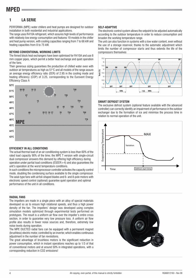
PERFORMA (MPE) water chillers and heat pumps are designed for outdoorinstallation in both residential and industrial applications�The range uses R410A refrigerant, which assures high levels of performancewith relatively low energy consumption and features 19 models in the chillerand heat pump version, with cooling capacities ranging from 7 to 66 kW andheating capacities from 8 to 75 kW�
BEYOND CONVENTIONAL WORKING LIMITSThe finned block heat exchangers have been optimised for R410A and use 8mm copper pipes, which permit a better heat exchange and quiet operationof the fans�Their generous sizing guarantees the production of chilled water even with outdoorairtemperaturesashighas51°Candallmodelsoftherangeassurean average energy efficiency ratio (EER) of 2�95 in the cooling mode and heating efficiency (COP) of 3�25, corresponding to the Eurovent Energy Efficiency Class A
EFFICIENCY IN ALL CONDITIONSThe actual thermal load of an air conditioning system is less than 60% of therated load capacity 90% of the time; the MPE T version with single-circuit dual compressor answers this demand by offering high efficiency duringoperation under partial load conditions (ESEER>4) and also guarantees theunit’s operation at the worst temperature conditions�In such conditions the microprocessor controller activates the capacity controlmode, doubling the condensing surface available to the single compressor�The axial-type fans with airfoil-shaped blades and 6- and 8-pole motors withelectronic speed control (optional) guarantee quiet operation and optimalperformance of the unit in all conditions�
1 LA SERIE
T54
T61
T69
T76
SELF-ADAPTIVEThe electronic control system allows the setpoint to be adjusted automaticallyaccording to the outdoor temperature in order to reduce consumption and broaden the working temperature range�The unit can also function in systems with a low water content, even without the use of a storage reservoir, thanks to the automatic adjustment which limits the number of compressor starts and thus extends the life of the compressors themselves
OFF
Tw,in
[°C]
t [s]
ON
15,5
15
14,5
14
13,5
13
12,5
12
11,5
ON ON
ON ON ON
OFF
420s
OFF OFF
600s
OFF
SMART DEFROST SYSTEMThe exclusive defrost system (optional feature available with the advanced controller) can correctly identify an impairment of performance in the outdoorexchanger due to the formation of ice and minimise the process time in relation to normal operation of the unit�
Time Defrost start time
MAX
Evap
orat
ioni
ng Te
mpe
ratu
re
Variation
RADIAL FANSThe impellers are made in a single piece with an alloy of special materials developed so as to ensure high rotational speeds, and thus a high power density of the fan� The impellers’ design was developed using complex simulation models optimized through experimental tests performed on prototypes� The result is a uniform air flow over the impeller’s entire cross section, in order to guarantee very low pressure loss� A uniform air flow profile also results in fewer noise sources and, therefore, extremely low noise levels during operation�The MPE DUCTED radial fans can be equipped with a permanent magnet (brushless) electric motor, controlled by an inverter, which enables continuous adjustment in the number of fan revolutions�The great advantage of brushless motors is the significant reduction in power consumption, which in instant operations reaches up to 1/3 of that of conventional motors and at around 50% in integrated operations, with a corresponding reduction in CO2 emissions!

5All copying, even partial, of this manual is strictly forbidden RG66012163 - Rev 00
STRUCTUREPainted galvanised sheet steel structure (RAL9002) for an attractive look and effective resistance to corrosive agents�Fastening devices are made of non-oxidizable materials, or carbon steel that has undergone surface-passivating treatments�The compressor compartment is completely sealed and may be accessed on 3 sides thanks to easy-to-remove panels that greatly simplify maintenance and/or inspection�Sound insulation, available on request, can further reduce the noise emissions of the unit�
CUSTOMISED HYDRAULIC KIT - High head pump made entirely of stainless steel, already configured for
use with mixtures of water and ethylene glycol up to 35% and provided with internal thermal protection�
It is housed in the compressor compartment and is easy to reach thanks to the removable perimeter panels�
- Expansion tank� - Safety valve� - Filling cock (included)�- Automatic vent valve�- Water differential pressure switch and outlet water temperature probe
with anti-freeze thermostat function�- Mechanical Y filter supplied as a standard feature on all models to protect
the evaporator (included)�
COOLING CIRCUIT- Scroll-type compressor (rotary up to 7 kW) housed in a compartment
that can be sound insulated�- Brazed plate heat exchangers made of STAINLESS STEEL and optimised
for use with R410A�- Finned block condenser with 8 mm copper piping and aluminium fins,
characterised by ample heat exchange surfaces�- Dehydrating filter�- Flow indicator with humidity indicator�- Thermostatic valve with external equalisation and integrated MOP
function�- Cycle-reversing valve (MPED H)�- Single-acting valves (MPED H)�- Liquid receiver (MPED H)- High and low pressure switches�- Safety valve�- Schrader valves for checks and/or maintenance�- Refrigerant pressure gauges (optional)
VENTILATION SECTIONStatically and dynamically balanced centrifugal fans with backward-curved blades, directly mounted on the electric motor�All units are equipped with phase-cut speed regulator controlled by the ratiometric pressure probe or by means of EC fans�The ventilation compartment is completely insulated with anti-condensation material and is separated from the compressor/electrical system compartment for inspection purposes when the unit is working (without interfering with the finned block exchanger)The absence of belt drive and the frontally removable fan considerably reduce maintenance work�The use of finned block heat exchangers with 8mm diameter pipes reduces pressure drops on the air side, thus significantly improving the noise levels of the units�
FINNED BLOCK HEAT EXCHANGERMade of 8mm diameter copper pipes and aluminium fins, generously sized� The special engineering of the heat exchangers allows defrost cycles to be carried out at maximum speed in the models with heat pump operation, which
brings clear benefits in terms of the integrated efficiency of the whole cycle�
ELECTRONIC MICROPROCESSOR CONTROLThe electronic control enables the complete control of the MPED unit� It can
be easily accessed through a polycarbonate flap with IP65 protection rating�
The self-adaptive logic enables the unit to operate even in systems where the water content is low, without the use of an inertial water storage reservoir� By reading the outdoor air temperature, it can automatically change the setpoint to adapt it to the outdoor load conditions or keep the unit running even in the harshest winter conditions� The basic controller comes complete with the MODBUS protocol and enables an immediate connection to ERGO networks�Main functions- Control over the temperature of water entering the evaporator�- Management of the defrosting function (MPED-H)- Control of fan speed (optional)- Complete alarm management�- Dynamic control of the setpoint according to the outdoor air temperature�- Can be connected to an RS485 serial line for supervisory / teleassistance
operation;- Option of connecting a remote terminal that duplicates the control
functions�Devices controlled:- Compressor- Fans- Cycle-reversing valve (MPED-H)�- Water circulation pump�- Antifreeze heating elements (optional)- Alarm signalling relayOn request, it is possible to install the advanced controller whose functions extend to:- LAN networks- Smart Defrost System
ELECTRIC CONTROL BOARDThe electric control board is constructed and wired in accordance with EEC Directive 73/23, Directive 89/336 on electromagnetic compatibility and related standards� Made of steel sheet, it is also protected by the enclosing panels of the machine�
OPTIONSIncorporable hydronic kitsCondensation controlLow noise executionRefrigerant pressure gaugesAntifreeze heating elements on the water circuitElectronic thermostatic valveHeat recovery 25% (chiller)Special exchangers (hydrophilic treatment, copper-copper, cataphoresis, anti-corrosion)Air flow rate setting system
ACCESSORIES AVAILABLERemote control boardsBase vibration dampersMetal grilles to protect exchangers
2 CONSTRUCTIVE FEATURES

MPED
6
MPED 07 - 08
All copying, even partial, of this manual is strictly forbidden RG66012163 - Rev 00
3 LAYOUT OF COMPONENTS
DESCRIPTION1. R410A-air heat-exchanger2. R410A-water heat-exchanger3. Fans4. Water differential pressure switch (fan housing)5. Automatic air purge valve6. Expansion vessel (fan housing)7. Water tank (accessory)9. 4-way valve (MPED H)10. Thermostatic valve
11. Water safety valve12. Liquid receiver13. Pump14. Compressor15. Refrigerant filter16. Low pressure switch and charge port17. High pressure switch and charge port18. Water gauge19. Water charge

7
MPED 10 - 15
All copying, even partial, of this manual is strictly forbidden RG66012163 - Rev 00
3 LAYOUT OF COMPONENTS
DESCRIPTION1. R410A-air heat-exchanger2. R410A-water heat-exchanger3. Fans4. Water differential pressure switch (fan housing)5. Automatic air purge valve6. Expansion vessel (fan housing)7. Water tank (accessory)9. 4-way valve (MPED H)10. Thermostatic valve
11. Water safety valve12. Liquid receiver (fan housing)13. Pump14. Compressor15. Refrigerant filter16. Low pressure switch and charge port17. High pressure switch and charge port18. Water gauge19. Water charge

MPED
8
MPED 18 - 27
All copying, even partial, of this manual is strictly forbidden RG66012163 - Rev 00
3 LAYOUT OF COMPONENTS
DESCRIPTION1. R410A-air heat-exchanger2. R410A-water heat-exchanger3. Fans4. Water differential pressure switch (fan housing)5. Automatic air purge valve6. Expansion vessel (fan housing)7. Water tank (accessory)9. 4-way valve (MPED H)10. Thermostatic valve
11. Water safety valve12. Liquid receiver (fan housing)13. Pump14. Compressor15. Refrigerant filter16. Low pressure switch and charge port17. High pressure switch and charge port18. Water gauge19. Water charge

9
MPED 28 - 40
All copying, even partial, of this manual is strictly forbidden RG66012163 - Rev 00
3 LAYOUT OF COMPONENTS
DESCRIPTION1. R410A-air heat-exchanger2. R410A-water heat-exchanger3. Fans4. Water differential pressure switch (fan housing)5. Automatic air purge valve6. Expansion vessel (fan housing)7. Water tank (accessory)9. 4-way valve (MPED H)10. Thermostatic valve
11. Water safety valve12. Liquid receiver (fan housing)13. Pump14. Compressor15. Refrigerant filter16. Low pressure switch and charge port17. High pressure switch and charge port18. Water gauge19. Water charge

MPED
10
MPED 54 - 66
All copying, even partial, of this manual is strictly forbidden RG66012163 - Rev 00
3 LAYOUT OF COMPONENTS
DESCRIPTION1. R410A-air heat-exchanger2. R410A-water heat-exchanger3. Fans4. Water differential pressure switch (fan housing)5. Automatic air purge valve6. Expansion vessel (fan housing)7. Water tank (accessory)9. 4-way valve (MPED H)10. Thermostatic valve
11. Water safety valve12. Liquid receiver (fan housing)13. Pump14. Compressor15. Refrigerant filter16. Low pressure switch and charge port17. High pressure switch and charge port18. Water gauge19. Water charge

11
MPED 30 - 45T
All copying, even partial, of this manual is strictly forbidden RG66012163 - Rev 00
3 LAYOUT OF COMPONENTS
DESCRIPTION1. R410A-air heat-exchanger2. R410A-water heat-exchanger3. Fans4. Water differential pressure switch (fan housing)5. Automatic air purge valve6. Expansion vessel (fan housing)7. Water tank (accessory)9. 4-way valve (MPED H)10. Thermostatic valve
11. Water safety valve12. Liquid receiver (fan housing)13. Pump14. Compressor15. Refrigerant filter16. Low pressure switch and charge port17. High pressure switch and charge port18. Water gauge19. Water charge

MPED
12
MPED 54T - 76T
All copying, even partial, of this manual is strictly forbidden RG66012163 - Rev 00
3 LAYOUT OF COMPONENTS
DESCRIPTION1. R410A-air heat-exchanger2. R410A-water heat-exchanger3. Fans4. Water differential pressure switch (fan housing)5. Automatic air purge valve6. Expansion vessel (fan housing)7. Water tank (accessory)8. 4-way valve (MPED H)9. Thermostatic valve
10. Water safety valve11. Liquid receiver (fan housing)12. Pump13. Compressor14. Refrigerant filter15. Low pressure switch and charge port16. High pressure switch and charge port17. Water gauge18. Water charge
13All copying, even partial, of this manual is strictly forbidden RG66012163 - Rev 00
4 MODELS AND CONFIGURATIONS
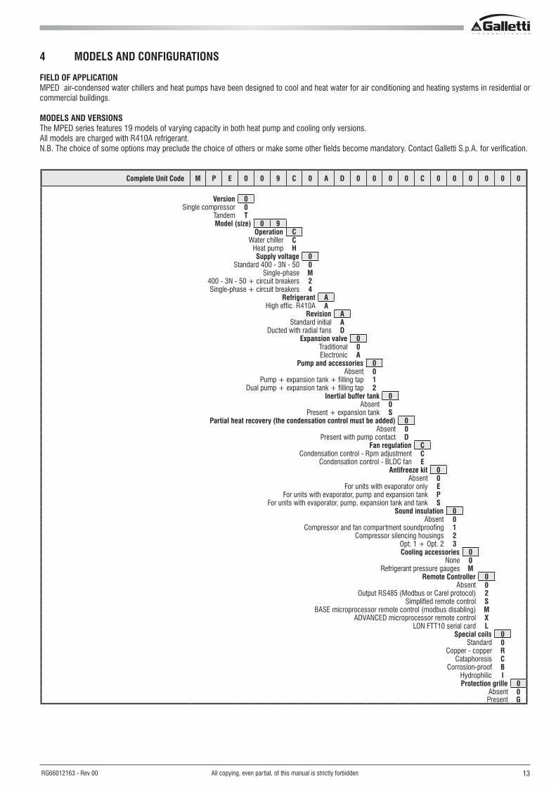
FIELD OF APPLICATIONMPED air-condensed water chillers and heat pumps have been designed to cool and heat water for air conditioning and heating systems in residential or commercial buildings�
MODELS AND VERSIONSThe MPED series features 19 models of varying capacity in both heat pump and cooling only versions�All models are charged with R410A refrigerant�N�B� The choice of some options may preclude the choice of others or make some other fields become mandatory� Contact Galletti S�p�A� for verification�
Complete Unit Code M P E 0 0 9 C 0 A D 0 0 0 0 C 0 0 0 0 0 0
Version 0Single compressor 0
Tandem TModel (size) 0 9
Operation CWater chiller C
Heat pump HSupply voltage 0
Standard 400 - 3N - 50 0Single-phase M
400 - 3N - 50 + circuit breakers 2Single-phase + circuit breakers 4
Refrigerant AHigh effic� R410A A
Revision AStandard initial A
Ducted with radial fans DExpansion valve 0
Traditional 0Electronic A
Pump and accessories 0Absent 0
Pump + expansion tank + filling tap 1Dual pump + expansion tank + filling tap 2
Inertial buffer tank 0Absent 0
Present + expansion tank SPartial heat recovery (the condensation control must be added) 0
Absent 0Present with pump contact D
Fan regulation CCondensation control - Rpm adjustment C
Condensation control - BLDC fan EAntifreeze kit 0
Absent 0For units with evaporator only E
For units with evaporator, pump and expansion tank PFor units with evaporator, pump, expansion tank and tank S
Sound insulation 0Absent 0
Compressor and fan compartment soundproofing 1Compressor silencing housings 2
Opt� 1 + Opt� 2 3Cooling accessories 0
None 0Refrigerant pressure gauges M
Remote Controller 0Absent 0
Output RS485 (Modbus or Carel protocol) 2Simplified remote control S
BASE microprocessor remote control (modbus disabling) MADVANCED microprocessor remote control X
LON FTT10 serial card LSpecial coils 0
Standard 0Copper - copper R
Cataphoresis CCorrosion-proof B
Hydrophilic IProtection grille 0
Absent 0Present G

MPED
14 All copying, even partial, of this manual is strictly forbidden RG66012163 - Rev 00
Complete Unit Code ... 0 1
Compressor options 0Absent 0
Power factor correction capacitors 1Soft starter 2
Power factor correction capacitors + Soft starter 3Air/water low temperature, low pressure switch, crankcase heating element (chiller), coil wire (PDC) 4
Control microprocessor 1BASE microprocessor 1
ADVANCED microprocessor 2Advanced microprocessor + kit GSM 3
Advanced microprocessor + clock card 4
ACCESSORIESO Horizontal air expulsion orientation (vertical STANDARD) M Manual air flow rate setting A Automatic flow rate setting (only ADVANCED microprocessor) – Base rubber vibration dumpers– Spring vibration dumpers kit– Simplified remote control– MYCHILLER BASE (RS485 is a mandatory accessory)– MYCHILLER PLUS (RS485 is a mandatory accessory)

15All copying, even partial, of this manual is strictly forbidden RG66012163 - Rev 00
5 TECHNICAL CHARACTERISTICS
5.1 RATED TECHNICAL DATA OF WATER CHILLERS
- Coolingcapacity:outdoorairtemperature35°C,watertemperature12°C/7°C- Sound power level measured according to standards ISO 3741 - ISO 3744 and EN 29614-1- Sound pressure level measured at a distance of 10 m and a height of 1�5 m above the ground in a free field (fan side)�- The maximum electrical input is the mains electricity that must be available in order for the unit to work�- The maximum current absorption refers to the current that will trigger the internal safety devices of the unit� It is the maximum current allowed in the unit� This value may never be exceeded; it must
be used as a reference for determining the size of the power supply line and the related safety devices (refer to the wiring diagram supplied with the units)�
MPED-C 007 M 008 M 008 010 M 010 013 015 018 020 024 027 028
Power supply V-ph-Hz 230-1-50 400-3-50 230-1-50 400-3-50
Cooling capacity (UNI EN 14511) kW 6,66 8,35 8,48 9,17 9,18 12,8 14,9 17,5 19,9 24,2 27,9 27,9
Total power input (UNI EN 14511) kW 2,40 3,51 3,24 3,75 3,81 4,61 5,56 7,01 7,87 8,55 9,37 9,73
EER (UNI EN 14511) 2,78 2,38 2,62 2,45 2,41 2,78 2,68 2,50 2,53 2,83 2,98 2,87
ESEER 2,96 2,87 3,05 2,92 2,93 3,36 3,29 2,92 2,89 3,15 3,16 3,45
Maximum power input kW 3,32 5,28 5,28 7,26 7,81 9,46 11,0 13,7 13,8 13,5 14,4 15,3
Maximum current absorption A 17 11 26 18 33 21 24 26 26 26 28 37
Starting absorbed current A 63 49 98 48 97 63 66 76 105 145 145 145
n°ofcompressors/circuits 1/1 1/1 1/1 1/1 1/1 1/1 1/1 1/1 1/1 1/1 1/1 1/1
Refrigerant charge kg 2,0 2,1 2,1 2,9 2,9 4,0 4,1 3,7 4,2 5,8 6,0 7,5
Low/high pressure switch bar 2 / 42 2 / 42 2 / 42 2 / 42 2 / 42 2 / 42 2 / 42 2 / 42 2 / 42 2 / 42 2 / 42 2 / 42
n°ofaxialfan 1 1 1 1 1 1 1 1 1 1 1 2
Air flow m3/h 3533 3533 3533 7666 7666 7192 7192 13384 13384 12191 12191 16276
Fan maximum head Pa 157 157 157 320 320 386 386 311 311 430 430 240
Fan net available head Pa 75 75 75 120 120 120 120 180 180 180 180 180
Water flow l/h 1148 1438 1461 1591 1592 2224 2584 3033 3444 4200 4832 4823
Diameter of hydrualic connections " 1 1 1 1 1 1 1 1,25 1,25 1,25 1,25 1,25
Water side pressure drop kPa 6 6 6 34 34 61 38 53 53 51 37 40
Available pressure head kPa 69 67 67 115 115 80 101 126 120 108 116 141
Water content escluding optionals dm3 1,5 1,5 1,5 3,0 3,0 3,0 3,0 4,0 4,0 4,0 4,0 5,5
Buffer tank dm3 20 20 20 30 30 30 30 50 50 50 50 125
Expansion tank dm3 1 1 1 5 5 5 5 5 5 5 5 8
Height mm 966 966 966 1247 1247 1247 1247 1565 1565 1565 1565 1988
Length mm 751 751 751 1012 1012 1012 1012 1131 1131 1131 1131 951
Depth mm 758 758 758 1224 1224 1224 1224 1274 1274 1274 1274 1823
Inlet + radiated sound power level dB(A) 74 73 73 75 75 74 74 79 79 78 78 80
Outlet sound power level dB(A) 75 75 75 82 82 81 81 84 84 81 81 89
Inlet + radiated sound power level (LOW NOISE)
dB(A) 70 70 70 70 70 71 71 76 76 75 75 77
Inlet + radiated sound pressure level dB(A) 46 45 45 47 47 46 46 51 51 50 50 52
Outlet sound pressure level dB(A) 47 47 47 54 54 53 53 56 56 53 53 61
Unit with pump and tank transport weight kg 123 127 127 211 211 216 219 265 281 297 313 427
Unit with pump and full tank operating weight kg 132 136 136 227 227 232 236 301 317 333 350 534

MPED
16 All copying, even partial, of this manual is strictly forbidden RG66012163 - Rev 00
5 TECHNICAL CHARACTERISTICS
5.1 RATED TECHNICAL DATA OF WATER CHILLERS
- Coolingcapacity:outdoorairtemperature35°C,watertemperature12°C/7°C- Sound power level measured according to standards ISO 3741 - ISO 3744 and EN 29614-1- Sound pressure level measured at a distance of 10 m and a height of 1�5 m above the ground in a free field (fan side)�- The maximum electrical input is the mains electricity that must be available in order for the unit to work�- The maximum current absorption refers to the current that will trigger the internal safety devices of the unit� It is the maximum current allowed in the unit� This value may never be exceeded; it must
be used as a reference for determining the size of the power supply line and the related safety devices (refer to the wiring diagram supplied with the units)�
MPED-C 032 035 040 054 066 T30 T34 T40 T45 T54 T61 T69 T76
Power supply V-ph-Hz 400-3-50
Cooling capacity (UNI EN 14511) kW 31,3 34,7 39,4 51,0 65,6 29,8 33,9 39,3 44,2 54,2 61,4 69,3 75,6
Total power input (UNI EN 14511) kW 11,3 12,7 13,9 19,8 26,2 11,5 13,8 14,8 17,6 21,7 24,7 26,8 30,8
EER (UNI EN 14511) 2,77 2,73 2,83 2,58 2,50 2,59 2,46 2,66 2,51 2,50 2,49 2,59 2,45
ESEER 3,33 3,33 3,44 3,43 3,04 3,63 3,56 3,68 3,57 3,15 3,19 3,43 3,46
Maximum power input kW 17,3 18,5 21,0 28,6 35,2 22,7 25,4 25,3 27,1 30,7 33,2 37,8 42,0
Maximum current absorption A 41 43 47 55 66 50 55 55 58 57 61 69 76
Starting absorbed current A 166 161 183 221 266 103 115 146 156 177 187 202 229
n°ofcompressors/circuits 1/1 1/1 1/1 1/1 1/1 2/1 2/1 2/1 2/1 2/1 2/1 2/1 2/1
Refrigerant charge kg 7,5 7,8 10,8 13,0 15,0 7,8 7,8 10,9 10,9 11,0 11,0 16,0 16,0
Low/high pressure switch bar 2 / 42 2 / 42 2 / 42 2 / 42 2 / 42 2 / 42 2 / 42 2 / 42 2 / 42 2 / 42 2 / 42 2 / 42 2 / 42
n°ofaxialfan 2 2 2 2 2 2 2 2 2 2 2 2 2
Air flow m3/h 16276 16276 15776 20048 20048 16276 16276 15776 15776 24933 24933 24354 24354
Fan maximum head Pa 240 240 285 515 515 267 267 307 307 160 160 200 200
Fan net available head Pa 180 180 180 180 180 180 180 180 180 120 120 120 120
Water flow l/h 5415 6008 6816 8829 11342 5156 5854 6799 7648 9378 10629 11989 13075
Diameter of hydrualic connections " 1,25 1,25 1,25 1,25 1,25 1,25 1,25 1,25 1,25 2 2 2 2
Water side pressure drop kPa 51 40 43 55 59 30 38 45 57 53 66 52 60
Available pressure head kPa 123 128 117 107 92 148 133 116 94 136 119 127 115
Water content escluding optionals dm3 5,5 5,5 5,5 5,5 7,0 8,0 5,5 5,5 5,5 5,5 7,0 8,0 11,0
Buffer tank dm3 125 125 125 125 125 125 125 125 125 125 125 125 125
Expansion tank dm3 8 8 8 8 8 8 8 8 8 8 8 8 8
Height mm 1988 1988 1988 1991 1991 1988 1988 1988 1988 2013 2013 2013 2013
Length mm 951 951 951 979 979 951 951 951 951 1182 1182 1182 1182
Depth mm 1823 1823 1823 1823 1823 1823 1823 1823 1823 2100 2100 2100 2100
Inlet + radiated sound power level dB(A) 80 80 82 84 84 79 79 79 79 85 85 85 87
Outlet sound power level dB(A) 89 89 86 85 85 86 86 86 86 88 88 88 88
Inlet + radiated sound power level (LOW NOISE)
dB(A) 77 77 79 81 81 76 76 76 76 82 82 82 84
Inlet + radiated sound pressure level dB(A) 52 52 54 56 56 51 51 51 51 57 57 57 59
Outlet sound pressure level dB(A) 61 61 58 57 57 58 58 58 58 60 60 60 60
Unit with pump and tank transport weight kg 456 487 516 521 558 448 484 521 555 643 665 685 786
Unit with pump and full tank operating weight kg 563 595 624 630 665 555 591 629 663 751 773 793 894

17All copying, even partial, of this manual is strictly forbidden RG66012163 - Rev 00
5 TECHNICAL CHARACTERISTICS
5.2 RATED TECHNICAL DATA OF HEAT PUMPS
- Coolingcapacity:outdoorairtemperature35°C,watertemperature12°C/7°C- Heatingcapacity:outdoorairtemperature7°Cdrybulband6.2°Cwetbulb,watertemperature40°C/45°C- Sound power level measured according to standards ISO 3741 - ISO 3744 and EN 29614-1- Sound pressure level measured at a distance of 10 m and a height of 1�5 m above the ground in a free field (fan side)�- The maximum electrical input is the mains electricity that must be available in order for the unit to work�- The maximum current absorption refers to the current that will trigger the internal safety devices of the unit� It is the maximum current allowed in the unit� This value may never be exceeded; it
must be used as a reference for determining the size of the power supply line and the related safety devices (refer to the wiring diagram supplied with the units)�* Seasonal energy efficiency class for LOW TEMPERATURE room heating under AVERAGE climatic conditions [EUROPEAN REGULATION No 811/2013]
MPED-H 007 M 008 M 008 010 M 010 013 015 018 020 024 027 028
Power supply V-ph-Hz 230-1-50 400-3-50 230-1-50 400-3-50
Cooling capacity kW 6,53 8,18 8,31 9,00 9,00 12,5 14,6 17,1 19,5 23,7 26,8 27,3
Cooling power input kW 2,45 3,55 3,29 3,82 3,81 4,76 5,71 7,12 7,86 8,64 9,73 8,56
EER 2,67 2,30 2,53 2,36 2,36 2,63 2,56 2,40 2,48 2,74 2,75 3,19
ESEER 2,96 2,87 3,05 2,92 2,93 3,36 3,29 2,92 2,89 3,15 3,16 3,45
Heating capacity kW 7,79 10,3 9,93 11,0 11,0 15,4 17,8 20,5 23,4 27,7 30,4 31,5
Heating power input kW 2,62 3,84 3,44 4,20 4,20 5,34 6,12 7,72 8,27 8,98 9,75 9,09
COP 2,97 2,68 2,89 2,62 2,62 2,88 2,91 2,66 2,83 3,08 3,12 3,47
SCOP 3,18 2,95 3,15 2,95 2,95 3,25 3,37 2,95 2,95 3,29 3,42 3,35
Energy Efficiency 125 115 123 115 115 127 132 115 115 129 134 131
Energy Efficiency Class* A+ A A+ A A A+ A+ A A A+ A+ A+
Maximum power input kW 3,32 5,28 5,28 7,26 7,81 9,46 11,0 13,7 13,8 13,5 14,4 15,3
Maximum current absorption A 17 11 26 18 33 21 24 26 26 26 28 37
Starting absorbed current A 63 49 98 48 97 63 66 76 105 145 145 145
n°ofcompressors/circuits 1/1 1/1 1/1 1/1 1/1 1/1 1/1 1/1 1/1 1/1 1/1 1/1
Refrigerant charge kg 2,0 2,1 2,1 2,9 2,9 4,0 4,1 3,7 4,2 5,8 6,0 7,5
Low/high pressure switch bar 2 / 42 2 / 42 2 / 42 2 / 42 2 / 42 2 / 42 2 / 42 2 / 42 2 / 42 2 / 42 2 / 42 2 / 42
n°ofaxialfan 1 1 1 1 1 1 1 1 1 1 1 2
Air flow m3/h 3533 3533 3533 7666 7666 7192 7192 13384 13384 12191 12191 16276
Fan maximum head Pa 157 157 157 320 320 386 386 311 311 430 430 240
Fan net available head Pa 75 75 75 120 120 120 120 180 180 180 180 180
Water flow in cooling mode l/h 1125 1409 1431 1560 1561 2179 2532 2973 3376 4116 4628 4727
Water flow in heat pump l/h 1348 1788 1720 1884 1884 2628 3053 3515 4020 4761 5237 5431
Diameter of hydrualic connections " 1 1 1 1 1 1 1 1,25 1,25 1,25 1,25 1,25
Water pressure drop (cooling) kPa 6 6 6 33 33 59 37 51 51 50 34 39
Water pressure drop (heating) kPa 8 8 8 46 46 85 52 72 71 64 44 50
Available pressure head (cooling) kPa 69 67 67 115 115 80 101 126 120 108 119 141
Available pressure head (heating) kPa 66 63 63 104 104 59 87 106 99 92 105 127
Water content escluding optionals dm3 1,5 1,5 1,5 3,0 3,0 3,0 3,0 4,0 4,0 4,0 4,0 5,5
Expansion tank dm3 20 20 20 30 30 30 30 50 50 50 50 125
Buffer tank dm3 1 1 1 5 5 5 5 5 5 5 5 8
Height mm 966 966 966 1247 1247 1247 1247 1565 1565 1565 1565 1988
Length mm 751 751 751 1012 1012 1012 1012 1131 1131 1131 1131 951
Depth mm 758 758 758 1224 1224 1224 1224 1274 1274 1274 1274 1823
Inlet + radiated sound power level dB(A) 74 73 73 75 75 74 74 79 79 78 78 80
Outlet sound power level dB(A) 75 75 75 82 82 81 81 84 84 81 81 89
Inlet + radiated sound power level (LOW NOISE)
dB(A) 70 70 70 70 70 71 71 76 76 75 75 77
Inlet + radiated sound pressure level dB(A) 46 45 45 47 47 46 46 51 51 50 50 52
Outlet sound pressure level dB(A) 46 45 45 47 47 46 46 51 51 50 50 52
Unit with pump and tank transport weight kg 126 130 130 215 215 220 224 270 286 302 318 433
Unit with pump and full tank opera-ting weight kg 135 139 139 232 232 237 241 306 322 338 355 540

MPED
18 All copying, even partial, of this manual is strictly forbidden RG66012163 - Rev 00
5 TECHNICAL CHARACTERISTICS
5.2 RATED TECHNICAL DATA OF HEAT PUMPS
- Coolingcapacity:outdoorairtemperature35°C,watertemperature12°C/7°C- Heatingcapacity:outdoorairtemperature7°Cdrybulband6.2°Cwetbulb,watertemperature40°C/45°C- Sound power level measured according to standards ISO 3741 - ISO 3744 and EN 29614-1- Sound pressure level measured at a distance of 10 m and a height of 1�5 m above the ground in a free field (fan side)�- The maximum electrical input is the mains electricity that must be available in order for the unit to work�- The maximum current absorption refers to the current that will trigger the internal safety devices of the unit� It is the maximum current allowed in the unit� This value may never be exceeded; it
must be used as a reference for determining the size of the power supply line and the related safety devices (refer to the wiring diagram supplied with the units)�* Seasonal energy efficiency class for LOW TEMPERATURE room heating under AVERAGE climatic conditions [EUROPEAN REGULATION No 811/2013]
MPED-H 032 035 040 054 066 T30 T34 T40 T45 T54 T61 T69 T76
Power supply V-ph-Hz 400-3-50
Cooling capacity kW 30,6 34,0 38,6 51,6 62,3 29,3 33,2 38,5 43,3 53,1 60,2 68,1 74,1
Cooling power input kW 10,1 11,6 12,8 17,7 24,1 10,3 12,6 13,7 16,5 19,2 22,2 24,5 28,5
EER 3,03 2,93 3,02 2,92 2,59 2,84 2,63 2,81 2,62 2,77 2,71 2,78 2,60
ESEER 3,33 3,33 3,44 3,43 3,04 3,63 3,56 3,68 3,57 3,15 3,19 3,43 3,46
Heating capacity kW 35,9 39,5 45,2 61,4 75,8 34,6 39,5 46,7 53,2 60,4 68,1 77,0 85,4
Heating power input kW 10,5 11,6 13,3 18,1 23,3 10,8 12,8 14,1 16,5 19,2 22,6 24,4 27,9
COP 3,42 3,41 3,40 3,39 3,25 3,20 3,09 3,31 3,22 3,15 3,01 3,16 3,06
SCOP 3,36 3,44 3,43 3,27 3,24 3,23 3,30 3,38 3,36 2,95 2,95 2,95 2,95
Energy Efficiency 132 135 135 128 127 127 130 133 132 115 115 115 115
Energy Efficiency Class* A+ A+ A+ A+ A+ A+ A+ A+ A+ A A A A
Maximum power input kW 17,3 18,5 21,0 28,6 35,2 22,7 25,4 25,3 27,1 30,7 33,2 37,8 42,0
Maximum current absorption A 41 43 47 55 66 50 55 55 58 57 61 69 76
Starting absorbed current A 166 161 183 221 266 103 115 146 156 177 187 202 229
n°ofcompressors/circuits 1/1 1/1 1/1 1/1 1/1 2/1 2/1 2/1 2/1 2/1 2/1 2/1 2/1
Refrigerant charge kg 7,5 7,8 10,8 13,0 16,0 7,8 7,8 10,9 10,9 13,0 13,0 19,5 19,5
Low/high pressure switch bar 2 / 42 2 / 42 2 / 42 2 / 42 2 / 42 2 / 42 2 / 42 2 / 42 2 / 42 2 / 42 2 / 42 2 / 42 2 / 42
n°ofaxialfan 2 2 2 2 2 2 2 2 2 2 2 2 2
Air flow m3/h 16276 16276 15776 20048 20048 16276 16276 15776 15776 24933 24933 24354 24354
Fan maximum head Pa 240 240 285 515 515 267 267 307 307 160 160 200 200
Fan net available head Pa 180 180 180 180 180 180 180 180 180 120 120 120 120
Water flow in cooling mode l/h 5307 5888 6681 8932 10776 5053 5737 6663 7495 9189 10423 11766 12818
Water flow in heat pump l/h 6173 6813 7800 10575 13063 5976 6818 8042 9155 10412 11733 13292 14730
Diameter of hydrualic connections " 1,25 1,25 1,25 1,25 1,25 1,25 1,25 1,25 1,25 2 2 2 2
Water pressure drop (cooling) kPa 49 39 42 56 54 29 37 44 55 51 64 50 58
Water pressure drop (heating) kPa 64 51 54 82 81 39 52 58 74 58 74 56 69
Available pressure head (cooling) kPa 123 128 117 107 92 148 133 116 94 136 119 127 115
Available pressure head (heating) kPa 109 114 99 76 52 131 113 95 65 126 100 110 87
Water content escluding optionals dm3 5,5 5,5 5,5 7,0 8,0 5,5 5,5 5,5 5,5 7,0 8,0 11,0 12,0
Expansion tank dm3 8 8 8 8 8 8 8 8 8 8 8 8 8
Buffer tank dm3 125 125 125 125 125 125 125 125 125 125 125 125 125
Height mm 1988 1988 1988 1991 1991 1988 1988 1988 1988 2013 2013 2013 2013
Length mm 951 951 951 979 979 951 951 951 951 1182 1182 1182 1182
Depth mm 1823 1823 1823 1823 1823 1823 1823 1823 1823 2100 2100 2100 2100
Inlet + radiated sound power level dB(A) 80 80 82 84 84 79 79 79 79 85 85 85 87
Outlet sound power level dB(A) 89 89 86 85 85 86 86 86 86 88 88 88 88
Inlet + radiated sound power level (LOW NOISE)
dB(A) 77 77 79 81 81 76 76 76 76 82 82 82 84
Inlet + radiated sound pressure level dB(A) 52 52 54 56 56 51 51 51 51 57 57 57 59
Outlet sound pressure level dB(A) 61 61 58 57 57 58 58 58 58 60 60 60 60
Unit with pump and tank transport weight kg 462 493 522 530 570 455 491 528 562 653 674 695 796
Unit with pump and full tank opera-ting weight kg 569 601 630 640 680 562 598 636 670 761 782 803 904

19All copying, even partial, of this manual is strictly forbidden RG66012163 - Rev 00
5 TECHNICAL CHARACTERISTICS
5.3 AIR FLOW RATE SETTING
The ducted unit’s nominal operating point varies depending on the pressure drop of the duct downstream from the fan; therefore, for every installation it is necessary to check that the fan’s air flow rate corresponds with the nominal air flow rate as a function of the duct’s size�
The ducted unit’s nominal operating point is calculated starting from the static pressure difference between the intake section (via an umbrella-handle shaped capillary tube) and the compartment’s inner section (via 4 measuring points located along the compartment’s circumference)� The air flow rate is computed on the basis of the static pressure difference according to the following equation:
qv=k∙√∆p qv in [m3/h],∆pin[Pa].Where k is a constant value supplied by the fan manufacturer according to the diameter of the compartment used�
The nominal air flow rate can be set as follows:• Manually, by means of a base microchiller 2 controller • Automatically, by means of an Advanced pCO controllerand sets a maximum value for the 0-10V signal of the condensation and evaporation control, which will correspond to the nominal air flow rate�
BASE CONTROLLER
Theinstallerwillvarythefanspeedinordertomeasure,usingadifferentialpressuregauge(belongingtohim/her),the∆pcorrespondingtothenominalairflowrate.Onboardtheunitwillbeprovidedthetableoftherelationshipbetween∆pandnominalflowrate.
ADVANCED CONTROLLER
Theautomaticcalibrationoftheflowrateisperformedwithaproportional-integrativelogicontheknown∆pvalue.By means of a differential pressure transducer, the pressure difference between the intake section and the compartment’s inner section can be converted into a 4-20mA or 0-10V signal to be sent to the microprocessor controller; the internal software will transform this signal into a differential pressure value�Theretroactiveactionofthelogicwillcomparethisvaluewiththeknownparameter∆p(dependingontheunitmodel),soastovarythenumberofrevolutionsofthefansand,therefore,theairflowrateuptothedesignvalue.Thepairofvalues,∆pandfanairflowrate,thusdeterminedissetintheadvanced microprocessor as the nominal operating point, which is useful for establishing the limit value for condensation/evaporation control� The auto-calibration procedure will be performed with the unit off and will have a preset maximum duration�

MPED
20 All copying, even partial, of this manual is strictly forbidden RG66012163 - Rev 00
6 PERFORMANCE
In order to define the performances of MPED subject to conditions different from rated conditions, a computer program for the correct choice of the units is provided by Galletti SpA�
With a few input data it will be possible to get information on the behaviour of a MPED referring to the desired operating conditions�
It will be sufficient to enter the following data:• Inlet air temperature • Inlet water temperature• Outlet water temperature • Ethylene glycol percentage (default 0)• Directivity factor and distance
Output data• Cooling / heating capacity• Water flow rate on user side • Water pressure drop on user side • Total power input • Total Absorbed current • Compressor Power Input • Compressor Absorbed current • EER • ESEER • COP• Pump available head
• Maximum current (FLA) • Inrush current (LRA) • Inrush Current with Soft Starter kit • Sound power level LW • Sound pressure level Lp
• Air flow rate • Number of fans • Fan input power • Fan input current • Compressors/Circuits • Tank Capacity (optional) • Power supply
The selection report generated by the software includes the drawing with overall dimensions�

21All copying, even partial, of this manual is strictly forbidden RG66012163 - Rev 00
6.4 INTEGRATED CAPACITIES
In the heat pump operation (heating mode), the actual heating capacities of units may be lower than the values shown in the table, due to defrosting cycles� To obtain the actual heating capacity, multiply the capacity values by the corrective coefficients given below�
ControlAirtemperature-drybulb(°C)
-5 0 5 >5
mchiller2 0,89 0,88 0,94 1
PCO XS 0,91 0,9 0,94 1
7 SOUND LEVEL
LEGENDLpA Total sound pressure level, weighted A, measured in an open field, at a distance of 10 m, with a directivity factor of 2�Lw Sound power level by octave band, not weightedLwA Total sound power level, weighted A
Model
Lw Lw A Lp A
125 Hz 250 Hz 500 Hz 1000 Hz 2000 Hz 4000 Hz 8000 Hz Total Low-noise version Total Low-noise
version
dB dB dB dB dB dB dB dB (A) dB (A) dB (A) dB (A)
MPED 007 M 59,2 65,2 67,7 69,0 66,3 67,4 58,2 75 73 47 45
MPED 008 M 57,8 63,9 66,4 67,7 64,9 66,0 56,8 73 71 45 43
MPED 008 57,8 63,9 66,4 67,7 64,9 66,0 56,8 73 71 45 43
MPED 010 M 71,0 77,0 79,5 80,8 78,0 79,1 69,9 86 84 58 56
MPED 010 71,0 77,0 79,5 80,8 78,0 79,1 69,9 86 84 58 56
MPED 013 69,6 75,6 78,1 79,4 76,6 77,7 68,5 85 83 57 55
MPED 015 69,6 75,6 78,1 79,4 76,6 77,7 68,5 85 83 57 55
MPED 018 72,8 78,8 81,3 82,6 79,8 80,9 71,7 88 86 60 58
MPED 020 72,8 78,8 81,3 82,6 79,8 80,9 71,7 88 86 60 58
MPED 024 70,6 76,6 79,1 80,4 77,6 78,7 69,5 86 84 58 56
MPED 027 67,9 73,9 76,5 77,8 75,0 76,1 66,9 83 81 55 53
MPED 028 72,3 78,3 80,9 82,1 79,4 80,5 71,3 88 86 60 58
MPED 032 72,3 78,3 80,9 82,1 79,4 80,5 71,3 88 86 60 58
MPED 035 72,3 78,3 80,9 82,2 79,4 80,5 71,3 88 86 60 58
MPED 040 72,3 78,3 80,8 82,1 79,4 80,5 71,3 88 86 60 58
MPED 054 69,9 75,9 78,5 79,8 77,0 78,1 68,9 85 83 57 55
MPED 066 69,9 75,9 78,5 79,8 77,0 78,1 68,9 85 83 57 55
MPED 030 T 75,2 81,2 83,7 85,0 82,2 83,4 74,1 91 89 63 61
MPED 034 T 75,2 81,2 83,7 85,0 82,2 83,4 74,1 91 89 63 61
MPED 040 T 74,5 80,5 83,0 84,3 81,5 82,7 73,4 90 88 62 60
MPED 045 T 74,5 80,5 83,0 84,3 81,5 82,7 73,4 90 88 62 60
MPED 054 T 71,1 77,1 79,7 81,0 78,2 79,3 70,1 86 84 58 56
MPED 061 T 71,1 77,1 79,7 81,0 78,2 79,3 70,1 86 84 58 56
MPED 069 T 70,7 76,7 79,2 80,5 77,7 78,9 69,7 86 84 58 56
MPED 076 T 72,1 78,1 80,7 81,9 79,2 80,3 71,1 87 85 59 57

MPED
22
-15
-10
-5
0
5
10
15
20
25
30
35
40
45
50
-6 -4 -2 0 2 4 6 8 10 12 14 16 18 20
AIR
TEM
P (°
C)
TW2 (°C)
opz 1
opz 1+2
opz 1+2 opz 1+2
EEV
EEV
STDopz 2
opz1+EEV
EEV
All copying, even partial, of this manual is strictly forbidden RG66012163 - Rev 00
8.2 OPERATING LIMITS IN HEAT PUMP MODE
RH Relative humidity of outdoor airTbs1 Outdoor temperature (dry bulb)Tw2 Water outlet temperature
Heat pump operation within the right area of the extended operating envelope (beyond standard limits) can be allowed only for units equipped with condensation control (or EC fans) and electronic expansion valve�
Parameters F08-F093-F03 refer to standard microprocessor controller�
Parameters GAIN and INT TIME are regulation parameters; they have to be modified inside the electronic expansion valve driver� Both modifications should only made in the factory or implemented on the field, but only by Galletti's authorized personnel�
8.3 THERMAL CARRIER FLUID
The units belonging to the MPED series can work with mixtures of water and up to 35% ethylene glycol�
8 OPERATING LIMITS
The graphs below illustrate the operating limits of MPED (in the case of continuous operation) in relation to the outlet water temperature and outdoor air temperature�
Warning The units are designed to work with water and air temperatures falling within the range defined by the operating limits�Attempting to operate the units beyond these limits could cause irreparable damage to the units themselves�
OPERATING LIMITS CHILLER HEAT PUMP MIN MAX MIN MAXInletwatertemperature(°C) 8 20 1 25 42
Outletwatertemperature(°C) 5 15 28 502
Thermaldifferentialofwater(°C) 3 8 3 8
Outdoorairtemperature(°C) 153 45 -5 20
1. Fortransitoryperiods(e.g.equipmentstartup)valuesupto25°Careallowed2. Valuethatmaybereachedonlyforoutdoorairtemperaturesexceeding0°C.3. Withcondensationcontrol:outdoorairTmin-10°C
8.1 OPERATING LIMITS IN CHILLER MODETBS1 Outdoor temperature (dry bulb)Tw2 Water outlet temperatureOPZ 1 Condensation controlOPZ 2 Glycol + low temperature optionOPZ 1+2 Condensation control + glycol + low temperature optionEEV Electronic valveSTD Standard

23
∆TW CPF/PT CPA CQw C∆pw1
3 0,975 1 1,63 2,64
4 0,99 1 1,24 1,53
5 1 1 1 1
6 1,015 1 0,85 0,72
7 1,03 1 0,74 0,54
8 1,04 1 0,65 0,42
All copying, even partial, of this manual is strictly forbidden RG66012163 - Rev 00
9 CALCULATION FACTORS
9.1 CHANGE IN OPERATING PARAMETERS WITH DT OTHER THAN 5°C
After identifying the unit’s performance in the terms of the desired outlet water temperature, correct the value by multiplying it by the following corrective coefficients�
∆TW Difference between water inlet temperature and water outlet temperature
CPF/PT Corrective coefficient of cooling/heating capacity
CPA Correction coefficient of electrical input
CQw Correction coefficient of water flow rate
C∆pw1 Correction coefficient of pressure drop
9.2 WATER AND GLYCOL MIXTURE
Based on the minimum outlet water temperature, you can derive the percentage of ethylene glycol and the corrective coefficient using the table below�
Warning The use of propylene glycol is not admitted with standard pumps� For further information, contact the manufacturer�
PERCENTAGE OF ETHYLENE GLYCOL 0% 10% 20% 30% 40%Minimumtemp.ofwaterproduced 5°C 2°C -5°C -10°C -15°C
Mixturefreezingtemp.(°C) 0°C -4°C -14°C -18°C -24°C
Capacity correction factor 1,000 0,998 0,994 0,989 0,983
Water flow rate correction factor 1,000 1,047 1,094 1,140 1,199
Pressure drop correction factor 1,000 1,157 1,352 1,585 1,860

MPED
24
MPED 07 ÷ 08
MPED 10 ÷ 45 T
0
2
4
6
8
10
12
14
16
0 500 1000 1500 2000 2500
�p
[kP
a]
Qw [l/h]
MPE 004 - 005 - 007
MPE 008
0
20
40
60
80
100
120
140
160
180
0 2000 4000 6000 8000 10000 12000
�p
[KP
a]
Qw [l/h]
MPE 010 - 013
MPE 015 - 018
MPE 020
MPE 024
MPE 027 - 032MPE 030T - 034T - 035
MPE 040 - 040T - 045T
All copying, even partial, of this manual is strictly forbidden RG66012163 - Rev 00
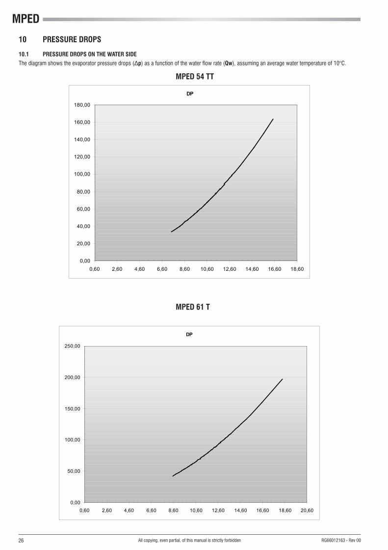
10 PRESSURE DROPS
10.1 PRESSURE DROPS ON THE WATER SIDE
Thediagramshowstheevaporatorpressuredrops(∆p) as a function of the water flow rate (Qw),assuminganaveragewatertemperatureof10°C.

25
MPED 54 ÷ 66
0
20
40
60
80
100
120
140
160
0 2000 4000 6000 8000 10000 12000 14000 16000 18000
�p
[KP
a]
Qw [l/h]
MPE 054
MPE 066
All copying, even partial, of this manual is strictly forbidden RG66012163 - Rev 00
10 PRESSURE DROPS
10.1 PRESSURE DROPS ON THE WATER SIDE
Thediagramshowstheevaporatorpressuredrops(∆p) as a function of the water flow rate (Qw),assuminganaveragewatertemperatureof10°C.
MPED
26
MPED 54 TT
DP
0,00
20,00
40,00
60,00
80,00
100,00
120,00
140,00
160,00
180,00
0,60 2,60 4,60 6,60 8,60 10,60 12,60 14,60 16,60 18,60
DP
0,00
50,00
100,00
150,00
200,00
250,00
0,60 2,60 4,60 6,60 8,60 10,60 12,60 14,60 16,60 18,60 20,60
MPED 61 T
All copying, even partial, of this manual is strictly forbidden RG66012163 - Rev 00
10 PRESSURE DROPS
10.1 PRESSURE DROPS ON THE WATER SIDE
Thediagramshowstheevaporatorpressuredrops(∆p) as a function of the water flow rate (Qw),assuminganaveragewatertemperatureof10°C.

27
DP
0,00
20,00
40,00
60,00
80,00
100,00
120,00
140,00
160,00
180,00
0,60 5,60 10,60 15,60 20,60 25,60
MPED 69 T
DP
0,00
20,00
40,00
60,00
80,00
100,00
120,00
140,00
160,00
180,00
200,00
0,60 5,60 10,60 15,60 20,60 25,60
MPED 76 T
All copying, even partial, of this manual is strictly forbidden RG66012163 - Rev 00
10 PRESSURE DROPS
10.1 PRESSURE DROPS ON THE WATER SIDE
Thediagramshowstheevaporatorpressuredrops(∆p) as a function of the water flow rate (Qw),assuminganaveragewatertemperatureof10°C.

MPED
28
MPED 07 ÷ 08
MPED 10 ÷ 66 - MPED 30 ÷ 45 T
0
1
1
2
2
3
0 500 1000 1500 2000
�p [kPa]
Qw [l/h]
MPE 004 - 008
0
5
10
15
20
25
0 2000 4000 6000 8000 10000 12000
∆p [kPa]
Qw [l/h]
MPE 010 - 028
MPE 032 - 066MPE T30 - T76
All copying, even partial, of this manual is strictly forbidden RG66012163 - Rev 00
10 PRESSURE DROPS
10.2 PRESSURE DROPS OF Y FILTER
The diagram shows the Y filter pressure drops (∆p) as a function of the water flow rate (Qw),assuminganaveragewatertemperatureof10°C.

29
MPED 07 ÷ 08
MPED 10 ÷ 45 T
0
10
20
30
40
50
60
70
0 500 1000 1500 2000 2500
Pu
[kP
a]
Qw [l/h]
MPE 004 - 005 - 007
MPE 008
0
20
40
60
80
100
120
140
160
180
200
0 2000 4000 6000 8000 10000 12000
Pu
[KP
a]
Qw [l/h]
MPE 010 - 013
MPE 015
MPE 020
MPE 024
MPE 027 - 028- 032
MPE 030T - 034T - 035
MPE 040 - 040T - 045T
MPE 018
All copying, even partial, of this manual is strictly forbidden RG66012163 - Rev 00
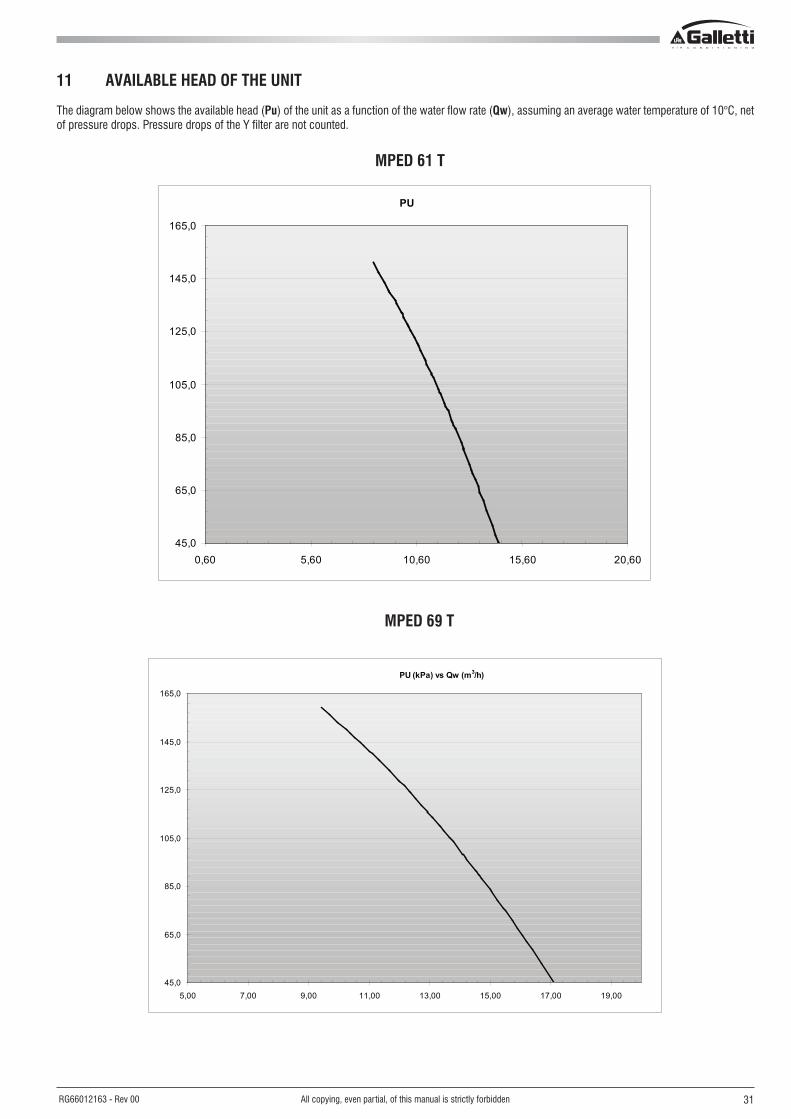
11 AVAILABLE HEAD OF THE UNIT
The diagram below shows the available head (Pu) of the unit as a function of the water flow rate (Qw),assuminganaveragewatertemperatureof10°C,netof pressure drops� Pressure drops of the Y filter are not counted�

MPED
30
MPED 54 ÷ 66
0
20
40
60
80
100
120
140
160
180
200
6000 8000 10000 12000 14000 16000 18000
Pu
[KP
a]
Qw [l/h]
MPE 066
MPE 054
PU
45,0
65,0
85,0
105,0
125,0
145,0
165,0
185,0
0,60 2,60 4,60 6,60 8,60 10,60 12,60 14,60 16,60 18,60
MPED 54 T
All copying, even partial, of this manual is strictly forbidden RG66012163 - Rev 00
11 AVAILABLE HEAD OF THE UNIT
The diagram below shows the available head (Pu) of the unit as a function of the water flow rate (Qw),assuminganaveragewatertemperatureof10°C,netof pressure drops� Pressure drops of the Y filter are not counted�
31
PU
45,0
65,0
85,0
105,0
125,0
145,0
165,0
0,60 5,60 10,60 15,60 20,60
MPED 61 T
PU (kPa) vs Qw (m3/h)
45,0
65,0
85,0
105,0
125,0
145,0
165,0
5,00 7,00 9,00 11,00 13,00 15,00 17,00 19,00
MPED 69 T
All copying, even partial, of this manual is strictly forbidden RG66012163 - Rev 00
11 AVAILABLE HEAD OF THE UNIT
The diagram below shows the available head (Pu) of the unit as a function of the water flow rate (Qw),assuminganaveragewatertemperatureof10°C,netof pressure drops� Pressure drops of the Y filter are not counted�

MPED
32
PU
45,0
65,0
85,0
105,0
125,0
145,0
165,0
0,60 5,60 10,60 15,60 20,60 25,60
MPED 76 T
All copying, even partial, of this manual is strictly forbidden RG66012163 - Rev 00
11 AVAILABLE HEAD OF THE UNIT
The diagram below shows the available head (Pu) of the unit as a function of the water flow rate (Qw),assuminganaveragewatertemperatureof10°C,netof pressure drops� Pressure drops of the Y filter are not counted�

33All copying, even partial, of this manual is strictly forbidden RG66012163 - Rev 00
12 WATER CIRCUIT
When setting up the water circuit of the unit, it is advisable to follow the directions below and in any case comply with local or national regulations�Connect the pipes to the chiller using flexible couplings to prevent the transmission of vibrations and to compensate thermal expansions�
It is recommended to install the following components on the pipes:- Temperature and pressure indicators for routine maintenance and monitoring of the unit� Checking the pressure on the water side will enable you to verify
whether the expansion tank is working efficiently and to promptly detect any water leaks within the equipment� - Traps on incoming and outgoing pipes for temperature measurements, which can provide a direct reading of the operating temperatures� - Regulating valves (gate valves) for isolating the unit from the water circuit�- Metal mesh filter (supplied), with a mesh size no greater than 1 mm, to be fitted on the inlet pipe to protect the exchanger from scale or impurities present
in the pipes�- Air vent valves, to be placed at the highest points of the water circuit for the purpose of bleeding air� (The internal pipes of the unit are fitted with small air
vent valves for bleeding the unit itself: this operation may only be carried out when the unit is disconnected from the power supply)�- Drainage valve and, where necessary, a drainage tank for emptying out the equipment for maintenance purposes or when the unit is taken out of service
at the end of the season� (A 1” drainage valve is provided on the optional water buffer tank: this operation may only be carried out when the unit is disconnected from the power supply)�
It is of fundamental importance that the incoming water supply is hooked up to the connection marked “Water Inlet”�Otherwise the evaporator would be exposed to the risk of freezing since the antifreeze thermostat would not be able to perform its function; moreover the reverse cycle would not be respected in the cooling mode, resulting in additional risks of malfunctioning�
The dimensions and position of plumbing connections are shown in the dimension tables at the end of the manual�
The water circuit must be set up in such a way as to guarantee that the nominal flow rate of the water supplied to the evaporator remains constant (+/- 15%) in all operating conditions� A standard feature of MPED units is a device for controlling the flow rate (flow switch or differential pressure switch) in the water circuit in the immediate vicinity of the evaporator�
12.1 SYSTEM WATER CONTENT AND CHARGING OF EXPANSION TANK
In models without a water storage reservoir it is necessary to assure that the content of water within the system does not fall below 3�5 litres/kW in the case of cooling-only models and 4�5 litres/kW in the case of heat pump models� This level is necessary to prevent the water temperature from falling below the indoor unit enabling threshold during defrost cycles�
N.B. kW in reference to rated capacityThe expansion tank is pre-charged to a pressure of 1�5 bars, sufficient for systems with a maximum height difference (H in the figure at the side) of 13 metres�For greater height differences, refer to the table below in order to adjust the charging pressure of the expansion tank accordingly�In no case should you exceed the maximum height difference Hmax = 35 m�
LEGENDH Height difference of systempi Charging pressure of expansion tankCmax Maximum system water content
Models H (m) pi (bar) Cmax (l)
MPE
D 00
4-00
8 <5 0,7 38
7 0,9 36
10 1,2 32
13 1,5 29
15 1,7 27
MPE
D 01
0-02
7 <13 1,5 145
15 1,7 133
20 2,2 105
25 2,7 77
30 3,1 49
MPE
D 02
8-06
6 T3
0-T4
5
<13 1,5 231
15 1,7 213
20 2,2 168
25 2,7 124
30 3,1 79

MPED
34 All copying, even partial, of this manual is strictly forbidden RG66012163 - Rev 00
12 WATER CIRCUITM
PED
(EVA
PORA
TOR
AND
PUM
P)M
PED
(EVA
PORA
TOR)
OPTIONAL
OPTIONAL
LEGENDVS Safety valveEV EvaporatorPD Water differential pressure switchMA Water gaugeVAS Air bleed hole
OPTIONAL ONLY FOR MPED28-66 / 30-45T / 54-76T RANGE
VE Expansion vesselP PumpRS DrainRC Water chargeVU Check valve

35All copying, even partial, of this manual is strictly forbidden RG66012163 - Rev 00
12 WATER CIRCUITM
PED
(EVA
PORA
TOR
AND
BUFF
ER T
ANK)
MPE
D (E
VAPO
RATO
R, P
UMP
AND
BUFF
ER T
ANK)
OPTIONAL
OPTIONAL
OPTIONAL ONLY FOR MPED28-66 / 30-45T / 54-76T RANGE
ONLY FOR MPED 10-27 RANGE
ONLY FOR MPED 10-27 RANGE
NOT AVAILABLE FOR MPED 07-08
NOT AVAILABLE FOR MPED 07-08
LEGENDVS Safety valveEV EvaporatorPD Water differential pressure switchMA Water gaugeVAS Air bleed hole
VE Expansion vesselP PumpRS DrainRC Water chargeVU Check valve

MPED
36
1 2 3 4 5
T>35°C
All copying, even partial, of this manual is strictly forbidden RG66012163 - Rev 00
12.2 DE-SUPERHEATER FOR PARTIAL HEAT RECOVERY
The partial heat recovery option is provided by a braze-welded plate heat exchanger placed inseries on the compressor delivery (typically in series in relation to the finned pack condenser)� Its size is designed to limit pressure drops on the refrigerant side to a minimum�All machines configured with heat recovery use as per standard modulating condensation control� In order toavoidanyunbalanceinthecoolingcircuit,iftherearestart-upswithverylowwatertemperaturesatrecovery(<35°C),thehydraulicrecoverycircuitmust be set up as indicated in the following figure: a low water temperature at recovery would cause a drop in the condensation temperature and therefore an insufficient pressure jump on the expansion valve with the ensuing risk of the safety devices being triggered�
1 Utility side2 Storage tank3 Mixing valve4 Circulation pump5 On-board de-superheater
The bulb of the 3-way mixer valve is placed at the de-superheater exchanger inlet� By mixing the hot water produced by the recovery with colder water from the tank, it reduces the time needed for the system to reach full operating capacity to a few moments� A buffer tank must be placed between the unit and the utility since the demand for hot water and its availability are not simultaneous, because it needs the compressors to be running�It should be pointed out that the heat recovery output is linked to the dispensed cooling output and that, therefore, in partial load situations it is also reduced just the same; this aspect must be taken into consideration for the dimensions of the buffer tank� The partial heat recovery option is supplied only with the de-superheater exchanger� The other components of the circuit laid out in the previous figure are not included in the supply�

37All copying, even partial, of this manual is strictly forbidden RG66012163 - Rev 00
13 ELECTRICAL DATA AND CONNECTIONS
- The maximum input power is the mains power that must be available in order for the unit to work�- The maximum current absorption refers to the current that will trigger the internal safety devices of the unit� It is the maximum current allowed in the unit This value may never be exceeded; it must be used as a reference for determining the size of the power supply line and the related safety devices (refer to the wiring diagram supplied with the units)� Cross-section area of cables: 4 A/mm2 approx�
MPED Maximum power input kW Maximum current absorption A Starting absorbed current A Fan motor rated power kW Fan motor rated current A Pump motor rated power kW Pump motor rated current A Power supply V/f/Hz Auxiliary power supply V/f/Hz Power cables mm2 PCD connecting cables mm2 PCDS connecting cables mm2 Safety fuse F A Circuit breaker IL A MPED Maximum power input kW Maximum current absorption A Starting absorbed current A Fan motor rated power kW Fan motor rated current A Pump motor rated power kW Pump motor rated current A Power supply V/f/Hz Auxiliary power supply V/f/Hz Power cables mm2 PCD connecting cables mm2 PCDS connecting cables mm2 Safety fuse F A Circuit breaker IL A
007M 008 M 008 010 M 010 013 015 018 020 024 027 028 032 3,32 5,28 5,28 7,26 7,81 9,46 11,0 13,7 13,8 13,5 14,4 15,3 17,317,0 26,0 11,0 32,9 17,9 21,0 23,6 25,8 25,8 26,1 27,7 37,4 40,763 98 49 97 48 63 66 76 105 145 145 145 166
0,369 0,369 0,369 1,11 1,04 0,84 0,84 2,13 2,25 1,78 1,78 2x1,25 2x1,251,82 1,82 1,82 4,49 4,49 3,56 3,56 3,45 3,45 2,87 2,87 2x5,45 2x5,450,20 0,20 0,20 0,29 0,29 0,31 0,32 0,37 0,37 0,37 0,37 0,55 0,550,90 0,90 0,90 2,10 2,10 2,25 2,32 2,72 2,72 2,72 2,72 2,74 2,74
230-1-50 400-3N-50 230-1-50 400-3N-50230-1-50
6 10 4 10 4 6 6 10 10 10 10 10 10AWG22 AWG22 AWG22 AWG22 AWG22 AWG22 AWG22 AWG22 AWG22 AWG22 AWG22 AWG22 AWG22
1 1 1 1 1 1 1 1 1 1 1 1 125 32 16 40 20 25 25 32 32 32 32 40 4025 32 16 40 20 25 25 32 32 32 32 40 40035 040 054 066 T30 T34 T40 T45 T54 T61 T69 T7618,5 21,0 27,9 34,4 22,7 25,4 25,3 27,1 30,4 32,8 37,6 41,842,7 47,2 51,8 63,0 49,9 54,5 54,5 57,5 55,9 60,1 68,3 75,5161 183 221 266 103 115 146 156 177 187 202 229
2x1,25 2x1,19 2x1,43 2x1,43 2x1,25 2x1,25 2x1,19 2x1,19 2x2,25 2x2,25 2x2,20 2x2,202x5,45 2x5,16 2x2,26 2x2,26 2x5,45 2x5,45 2x5,16 2x5,16 2x3,64 2x3,64 2x3,55 2x3,550,55 0,55 1,26 1,26 0,55 0,55 0,55 0,55 1,26 1,26 1,26 1,262,74 2,74 5,9 5,9 2,74 2,74 2,74 2,74 5,90 5,90 5,90 5,90
400-3N-50230-1-50
16 16 16 10 16 16 16 16 16 16 25 25AWG22 AWG22 AWG22 AWG22 AWG22 AWG22 AWG22 AWG22 AWG22 AWG22 AWG22 AWG22
1 1 1 1 1 1 1 1 1 1 1 150 50 63 63 50 63 63 63 63 63 80 8050 50 63 63 50 63 63 63 63 63 80 80

MPED
38
R
-IL
-IL-FL
L1
L1L2
T1T2
L1L2L3N
L2L3N
-FL
-IG
1 3 5 N
2 4 6 N
400
230
L N PE
L
N
PE
1 50
3+N 50
S T N P
PE
E
-IG
All copying, even partial, of this manual is strictly forbidden RG66012163 - Rev 00
13 ELECTRICAL DATA AND CONNECTIONS
DIAGRAM SHOWING ELECTRICAL CONNECTIONS BETWEEN MPED AND PCDS / PCD REMOTE CONTROL PANEL
NOTE: On the terminal block of the electric control panel a voltage of 24V will be present at the 50/24V terminals in the event of an alarm; if it is desired to interface with a voltage-free contact, a relay must be applied for this purpose by the installer�
GENE
RAL
ALAR
M S
IGNA
L
COOL
ING/
HEAT
ING
REM
OTE
SELE
CTIO
N
ON/O
FF (S
TAND
-BY)
SW
ITCH
PCDS
POW
ER S
UPPL
Y
USE
SHIE
LDED
CAB
LEW
ITH
ONE
TWIS
TED
PCD POWER SUPPLY
ELECTRIC BOARD TERMINAL
ELECTRIC BOARD TERMINAL

39
MPED 07 ÷ 08
All copying, even partial, of this manual is strictly forbidden RG66012163 - Rev 00
14 OVERALL DIMENSIONS
LEGEND
1 Water in 1" female
2 Water out 1" female
3Safety valve discharge outlet provided with rubber ring holder
4 Water supply 1/2" male (optional tap)
5 Drain manifold 1/2" female
6 Power supply Ø 28 mm
7 Electric control board
8 Dampers fastening points (accessory)
A x B Duct outlet dimensions

MPED
40
MPED 10 ÷ 15
All copying, even partial, of this manual is strictly forbidden RG66012163 - Rev 00
14 OVERALL DIMENSIONS
LEGEND
1 Water in 1" female
2 Water out 1" female
3Safety valve discharge outlet provided with rubber ring holder
4 Water supply 1/2" male (optional tap)
5 Drain manifold 1/2" female
6 Power supply Ø 28 mm
7 Electrical control board
8 Dampers fastening points (accessory)
A x B Duct outlet dimensions

41
MPED 18 ÷ 27
All copying, even partial, of this manual is strictly forbidden RG66012163 - Rev 00
14 OVERALL DIMENSIONS
LEGEND
1 Water in 1" 1/4 female
2 Water out 1" 1/4 female
3Safety valve discharge outlet provided with rubber ring holder
4 Water supply 1/2" male (optional tap)
5 Drain manifold 1/2" female
6 Power supply Ø 28 mm
7 Electrical control board
8 Dampers fastening points (accessory)
A x B Duct outlet dimensions

MPED
42
MPED 28 ÷ 40 - MPED 30 ÷ 45 T
All copying, even partial, of this manual is strictly forbidden RG66012163 - Rev 00
MPED 28-45 WITH BUFFER TANK MPED 30-45 T
14 OVERALL DIMENSIONS
LEGEND
1 Water in 1" 1/4 female
2 Water out 1" 1/4 female
3Safety valve discharge outlet provided with rubber ring holder
4 Water supply 1/2" male (optional tap)
5 Drain manifold 1/2" female
6 Power supply Ø 37 mm
7 Electrical control board
8 Dampers fastening points (accessory)
A x B Duct outlet dimensions

43
MPED 54 ÷ 66
All copying, even partial, of this manual is strictly forbidden RG66012163 - Rev 00
14 OVERALL DIMENSIONS
MPED 54-66 WITH BUFFER TANK
LEGEND
1 Water inlet 2" female
2 Water outlet 2" female
3 Safety valve discharge outlet provided with rubber ring holder
4 Water supply ½” male
5 Water drainage ½" female
6 Power supply
7 Electric control board
8 Fastening points for vibration dampers (accessory)
9 Desuperheater water inlet 1” female
10 Desuperheater water outlet 1” female
A x B Duct outlet dimensions

MPED
44
MPED 54 ÷ 76T
All copying, even partial, of this manual is strictly forbidden RG66012163 - Rev 00
14 OVERALL DIMENSIONS
LEGEND
1 Water inlet 2" female
2 Water outlet 2" female
3Safety valve discharge outlet provided with rubber ring holder
4 Water supply ½” male
5 Water drainage ½" female
6 Power supply
A x B Duct outlet dimensions

45All copying, even partial, of this manual is strictly forbidden RG66012163 - Rev 00
14 OVERALL DIMENSIONS
The table shows the dimensions of the duct outlet� For the frames with fans located on top of the unit (models 28 - T76), the duct can be installed by removing the top panel or side panel of the fan compartment, as shown respectively in the top and front views of the dimensional diagrams� The isometric view shows, for example, the case of ducting on the side panel�
DUCT DIMENSIONS
A (mm)B (mm)
DUCT DIMENSIONS
A (mm)B (mm)
007M 008 M 008 010 M 010 013 015 018 020 024 027 028 032
535 535 535 605 605 605 605 1015 1015 1015 1015 1320 1320300 300 300 409 409 409 409 487 487 487 487 420 420
035 040 054 066 T30 T34 T40 T45 T54 T61 T69 T76
1320 1320 1320 1320 1320 1320 1320 1320 1394 1394 1394 1394420 420 420 420 420 420 420 420 420 420 420 420

MPED
46
1
MPED 07 - 08
2
All copying, even partial, of this manual is strictly forbidden RG66012163 - Rev 00
15 INSTALLATION CLEARANCE REQUIREMENTS AND SITING
To guarantee the proper functioning of the unit and access for maintenance purposes, it is necessary to comply with the minimum installation clearance requirements shown in figures 1, 2, 3 and 4�There must be no obstacles blocking the path of the air flow from the fans�Avoid any and all situations of backflow of hot air between air outlet and inlet of the unit�If even only one of the above conditions is not fulfilled, please contact the manufacturer to check for feasibility�
In the design of the MPED series, special care has been taken to minimise noise and vibrations transmitted to the ground� Even greater insulation may be obtained, however, by using vibration damping base supports (available as optional accessories)� If vibration damping base supports are adopted, it is strongly recommended also to use vibration damping couplings on the water pipes�Whenever the unit is to be sited on unstable ground (various types of soil, gardens, etc�) it is a good idea to provide a supporting base of adequate dimensions�
Warning heat pump units produce condensation while operating in the heating mode�
MPED water chillers and heat pumps are air-cooled units suitable for indoor installation� It is necessary to install air intake and outlet ducts that must be sized for the nominal air flow rate and the available useful pressure of each model� At the same time avoid installations that may allow air recirculation to take place between the intake and the outlet�The figure shows a typical installation with air outlet from above�It is important to bear in mind the following aspects when choosing the best site for installing the unit:- size and origin of water pipes;- Location of the power supply;- Solidity of the supporting surface;- To position the unit so that prevalent winds do not alter the fan air flow)�- Avoid the transmission of noise and vibrations through the technical compartment and duct structure� To do this, use base vibration damping accessories and vibration dampers on the air outlet� If vibration damping base supports are adopted, it is strongly recommended also to use vibration damping couplings on the water pipes�- Ensure proper accessibility for maintenance or repairs�
This device is not intended to be used by children or by people with physical, sensory or mental impairments, except under supervision. Make sure that children do not have access to the device.
HEAT EXCHANGER WATER CONNECTION SIDE
EXCHANGER SIDEELEC
TRIC
AL B
OX
FAN SIDE

47
MPED 28 - 66 / 30 - 45 T / 54 - 76 T
All copying, even partial, of this manual is strictly forbidden RG66012163 - Rev 00
MPED 10 - 15 MPED 18 - 27
MPED 28 - 66 / 30 - 45 T MPED 54 - 76 T
HEAT EXCHANGER WATER CONNECTION SIDE
ELEC
TRIC
AL B
OX
EXCHANGER SIDE
HEAT EXCHANGER WATER CONNECTION SIDE
EXCHANGER SIDEELEC
TRIC
AL B
OX
MPED N° DAMPERS04 - 08 4
10 - 15 4
18 - 27 4
28 - 66 6
30 - 45 T 6
54 - 76 T 6
15.1 DAMPERS SITING
DAMPERS
MPED 54-76T SIDE DISCHARGE W
ATER
ELEC
TRIC
AL B
OX
EXCHANGER SIDE
HEAT EXCHANGER WATER CONNECTION SIDE
MPED 30-45T SIDE DISCHARGE W
ATER
HEAT EXCHANGER WATER CONNECTION SIDE
ELEC
TRIC
AL B
OX
EXCHANGER SIDE
FAN SIDE FAN SIDE

www.galletti.it
40010 Bentivoglio (BO) Via Romagnoli 12/a Tel� 051/8908111 - Fax� 051/8908122Company UNI EN ISO 9001 and OHSAS 18001 certified