mpc8308 network smart gateway reference design platform
TRANSCRIPT

MPC8308 Network Smart Gateway
Reference Design Platform Quick Start Guide
Rev 2.0 11/2011
MPC8308NSG Quick Start Guide 2
How to Reach Us: Home Page: www.freescale.com Web Support: http://www.freescale.com/support USA/Europe or Locations Not Listed: Freescale Semiconductor, Inc. Technical Information Center, EL516 2100 East Elliot Road Tempe, Arizona 85284 1-800-521-6274 or +1-480-768-2130 www.freescale.com/support Europe, Middle East, and Africa: Freescale Halbleiter Deutschland GmbH Technical Information Center Schatzbogen 7 81829 Muenchen, Germany +44 1296 380 456 (English) +46 8 52200080 (English) +49 89 92103 559 (German) +33 1 69 35 48 48 (French) www.freescale.com/support Japan: Freescale Semiconductor Japan Ltd. Headquarters ARCO Tower 15F 1-8-1, Shimo-Meguro, Meguro-ku, Tokyo 153-0064 Japan 0120 191014 or +81 3 5437 9125 [email protected] Asia/Pacific:
Freescale Semiconductor China Ltd. Exchange Building 23F No. 118 Jianguo Road Chaoyang District Beijing 100022 China +86 10 5879 8000 [email protected] For Literature Requests Only: Freescale Semiconductor Literature Distribution Center P.O. Box 5405 Denver, Colorado 80217 1-800-441-2447 or +1-303-675-2140 Fax: +1-303-675-2150 [email protected]
Information in this document is provided solely to enable system and software implementers to use Freescale Semiconductor products. There are no express or implied copyright licenses granted hereunder to design or fabricate any integrated circuits or integrated circuits based on the information in this document.
Freescale Semiconductor reserves the right to make changes without further notice to any products herein. Freescale Semiconductor makes no warranty, representation or guarantee regarding the suitability of its products for any particular purpose, nor does Freescale Semiconductor assume any liability arising out of the application or use of any product or circuit, and specifically disclaims any and all liability, including without limitation consequential or incidental damages ―Typical‖ parameters that may be provided in Freescale Semiconductor data sheets and/or specifications can and do vary in different applications and actual performance may vary over time. All operating parameters, including ―Typicals‖, must be validated for each customer application by customer‘s technical experts. Freescale Semiconductor does not convey any license under its patent rights nor the rights of others. Freescale Semiconductor products are not designed, intended, or authorized for use as components in systems intended for surgical implant into the body, or other applications intended to support or sustain life, or for any other application in which the failure of the Freescale Semiconductor product could create a situation where personal injury or death may occur. Should Buyer purchase or use Freescale Semiconductor products for any such unintended or unauthorized application, Buyer shall indemnify and hold Freescale Semiconductor and its officers, employees, subsidiaries, affiliates, and distributors harmless against all claims, costs, damages, and expenses, and reasonable attorney fees arising out of, directly or indirectly, any claim of personal injury or death associated with such unintended or unauthorized use, even if such claim alleges that Freescale Semiconductor was negligent regarding the design or manufacture of the part.
Federal Communications Commission Radio Frequency Interference Statement
This device complies with Part 15 of the FCC rules. Operation is subject to the following two conditions: (1) This device may not cause harmful interference and (2) This device must accept any interference received, including interference that might cause undesired operation. Changes or modifications to this equipment not expressly approved by Freescale could void the user‘s authority to operate the equipment. This equipment has been tested and found to comply with the limits for a Class B digital device, pursuant to part 15 of the FCC Rules. These limits are designed to provide reasonable protection against harmful interference in a residential installation. This equipment generates uses and can radiate radio frequency energy and, if not installed and used in accordance with the instructions, may cause harmful interference to radio communications. However, there is no guarantee that interference will not occur in a particular installation. If this equipment does cause harmful interference to radio or television reception, which can be determined by turning the equipment off and on, the user is encouraged to try to correct the interference by one or more of the following measures: — Reorient or relocate the receiving antenna. — Increase the separation between the equipment and receiver. — Connect the equipment into an outlet on a circuit different from that to which the receiver is connected. — Consult the dealer or an experienced radio/TV technician for help.
Freescale and the Freescale logo are trademarks of Freescale Semiconductor, Inc. Reg. U.S. Pat. & Tm. Off. Flexis and Processor Expert are trademarks of Freescale Semiconductor, Inc. All other product or service names are the property of their respective owners.
© 2011 Freescale Semiconductor, Inc. All rights reserved.
MPC8308NSG Quick Start Guide 3
Contents
1. Introduction .............................................................................................................. 4
2. Hardware Equipment List for the Demonstration ................................................. 5
Hardware Platforms ................................................................................................................................ 5
Peripherals .............................................................................................................................................. 5
3. Software Required for Demonstration ................................................................... 5
4. Safely power off the reference platform ................................................................ 8
5. Zigbee Smart Energy (Metering) ............................................................................. 9
6. Zigbee Home Automation ..................................................................................... 10
7. Digital Living Network Alliance (DLNA) ............................................................... 12
Setup Reference Platform as DLNA Server ...................................................................................... 12
Setup DLNA Clients (Windows PC, iPad, iPhone, iPod) ................................................................... 12
For PC with Windows XP ................................................................................................................... 12
Using Mezzmo as DLNA Client .......................................................................................................... 12
Wireless Performance Data ............................................................................................................... 14
8. Voice over Internet Protocol (VoIP) ...................................................................... 15
9. Network Video Recorder (NVR) ............................................................................ 16
Using NVR Auto-Detect ........................................................................................................................ 16
Ensure that the VLC player is installed and the Firewall and Proxy connections are deactivated. ..... 16
Appendix A .................................................................................................................. 19
Appendix B .................................................................................................................. 21

MPC8308NSG Quick Start Guide 4
1. Introduction
This quick start guide provides the necessary step by step instructions to set up and demonstrate the capabilities of PowerQUICC MPC8308 Network Smart Gateway Reference Design Platform.
PowerQUICC MPC8308 based Networked Smart Gateway Solution leverages high performance, easy to use, optimized open source integrated applications. The reference Design platform performs the following demonstrations as described in this Quick Start Guide.
High performance Wireless access point (AP) Gateway with easy-to-use, integrated and optimized open source applications that support the use of wireless web-based handsets or thin clients like laptop PCs, iPhone, iPad, and iPod-touch perform remote monitoring and control of various cloud services such as:
NSG (Network Smart Gateway) solution and Home Automation with Modlet
(Smart plug) enables remote monitoring and control of smart meter and
appliances
NOTE
The ThinkEco modlets are only rated for 110V, please use voltage adapter for 220/240V
source
Video Surveillance (NVR) solution supporting wire or wireless IP cameras with
Auto detection
Media Gateway solution supporting the following protocols or applications
a. DLNA (Digital Living Network Alliance) compliance solution – Streaming Video and Music files from Reference Platform to DLNA client device (e.g. Google TV, ipad, iphone, ipod touch)
b. Voice over IP (VoIP) solution leveraging open source Asterisk IP/PBX - VoIP (Voice over Internet Protocol) – Streaming Voice packets
Bit Torrent solution supporting peer to peer networking
Hardware and Software Requirements for the demonstration setup:
a. Unless stated separately, all the hardware will be provided inside the shipment box for easy setup in the Demo on Demand Kits.
b. Unless stated separately, all the Software files will be either on the SD cards or the USB memory stick inside the shipment box for Demo on Demand Kits. Additional Freescale Compass/Extranet Link will be provided for Software update. Always check with Compass/Extranet site for the latest software information.
NOTE
The Demo on Demand Kit (DoD) has the hardware accessories/peripherals listed below in the
kit. Typically these are not included with the MPC8308NSG platform.

MPC8308NSG Quick Start Guide 5
2. Hardware Equipment List for the Demonstration
Hardware Platforms
MPC8308NSG
Peripherals
Smart Energy Meter
ThinkEco Modlet and corresponding USB Dongle
SD Card
IP Cameras – Axis Model M1011 (2 sets)
IP phones – Grandstream BT201 (2 sets)
Gigabit Ethernet Switch
Ethernet CAT6 Cables (6)
Power Extension Cords (2)
Quick Start Guide and Poster
Scotch tape and Velco tape
Optional Equipments (Not provided inside the box)
Thin clients (iPad, iPod and iPhone) for DLNA and Smart Energy Gateway demo
(iPad needs to have Fusion Stream application installed and iPod needs to have
iMedia Suite application installed to act as the DLNA client)
Large display monitor (19” monitor, 42” SMART TV/HDTV, etc.)
Audio speakers
Desktop or laptop computer ( to configure the GUI through HTTP and act as the
DLNA client) The PC should equipped with either the Microsoft XP (32-bit) or
Window 7 Professional (32-bit) operating system
3. Software Required for Demonstration
All the software required in the demonstration should be either pre-flashed or preloaded in the USB Memory stick or SD memory card for Demo on Demand kits. Download the file ―PowerPCDemoSoftware.zip‖ and it will contain all the software and video clips required for the demonstration.

MPC8308NSG Quick Start Guide 6
Figure 1: Basic Setup Diagram
Figure 2: MPC8308NSG
Basic Setup Instructions for MPC8308nSG Reference Platform
1. Setup the Hardware according to the Figure 1.
2. Configure the IP address of the network card of the windows PC
a. Go to Start Control Panel Network Connection Local Area Network.
WAN
PORT
T
Po
UART
PORT
T
Po
LAN
PORT
T
Po
POWER
Po
MPC8308NSG Quick Start Guide 7
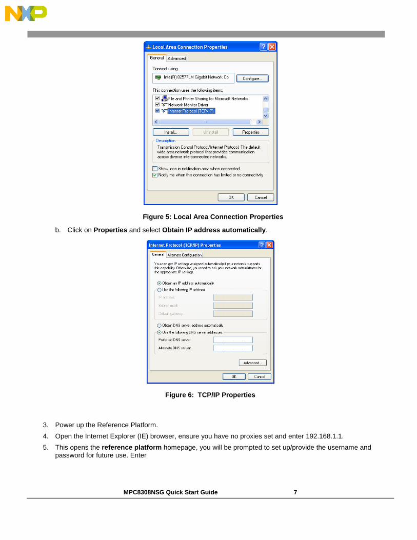
Figure 5: Local Area Connection Properties
b. Click on Properties and select Obtain IP address automatically.
Figure 6: TCP/IP Properties
3. Power up the Reference Platform.
4. Open the Internet Explorer (IE) browser, ensure you have no proxies set and enter 192.168.1.1.
5. This opens the reference platform homepage, you will be prompted to set up/provide the username and password for future use. Enter

MPC8308NSG Quick Start Guide 8
Username: root
Password: root
6. Press Enter.
Check Remember the username and password checkbox for future use.
The webpage is shown as follows:
Figure 7: Homepage
4. Safely power off the reference platform
To power off the reference platform safely without the loss of data or without corrupting the files in the mounted devices, follow the steps below:
1. Connect the serial cable to the SPI interface of the board and the COM port of the PC
2. Hit enter to go to the “root@FSL#” prompt
3. Type “reboot”
4. Hit the enter key to stop the booting process (i.e: when the counter starts) to go to the u-boot mode
5. Now the board can be power off.
Before starting to deploy any applications; please power ON the board. Let the zigbee LED be stable and then proceed further to do the application.

MPC8308NSG Quick Start Guide 9
5. Zigbee Smart Energy (Metering)
This application uses Mozilla/FireFox only. Please open a Firefox browser window
and type 192.168.1.1
This section describes the procedure to demonstrate the remote monitoring of electrical power meter through Zigbee
Make sure the zigbee LED light on the MPC8308 NSG is continuously on (stable)
1. Connect the power strip to the power outlet (shorter cable) of the Meter; Plug the power cord of the meter to the
power and power on the meter.
In the Mozilla web browser, go to: //192.168.1.1/home.html (User name: root,
Password: root)
The metering device dialog box should show the same reading as the power
meter and should update the reading periodically
The web page is shown below.
Figure 8: Smart Metering and Home Automation web page
MPC8308NSG Quick Start Guide 10
6. Zigbee Home Automation
This application uses Mozilla/FireFox only. Please open a Firefox browser window
and type 192.168.1.1
This section describes the procedure to demonstrate the remote control of electrical appliances through Zigbee
(e.g. Remote Power on/off device and monitoring power consumption of each appliance)
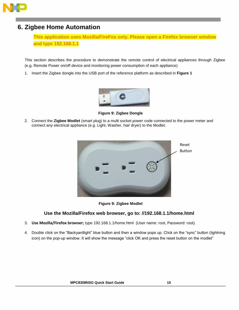
1. Insert the Zigbee dongle into the USB port of the reference platform as described in Figure 1
Figure 9: Zigbee Dongle
2. Connect the Zigbee Modlet (smart plug) to a multi socket power code connected to the power meter and connect any electrical appliance (e.g. Light, Washer, hair dryer) to the Modlet.
Figure 9: Zigbee Modlet
Use the Mozilla/Firefox web browser, go to: //192.168.1.1/home.html
3. Use Mozilla/Firefox browser; type 192.168.1.1/home.html (User name: root, Password: root).
4. Double click on the ―Backyardlight‖ blue button and then a window pops up. Click on the ―sync‖ button (lightning
icon) on the pop-up window. It will show the message ―click OK and press the reset button on the modlet‖
Reset
Button

MPC8308NSG Quick Start Guide 11
5. Click OK and then press ―reset‖ button on the Modlet (Smart plug) and hold it for 8-10 seconds
6. If there is a message in the response page that said ―Invalid message‖; repeat the previous step until you get
the correct acknowledgement
7. To turn on the appliance connected to the upper socket (socket close to the button) of the Modlet, click ―ON‖ in
the backyard light pop-up window
8. To turn on the appliance connected to the upper socket (socket close to the button) of the Modlet, click ―OFF‖ in
the backyard light pop-up window
9. The power consumed by both appliances will be displayed in the same pop-up window
10. To perform the above mentioned 3 tasks for the appliance connected to the lower socket of the Modlet, select
―Dryer‖ instead of ―backyard light‖.
To check the CPU utilization and the processes running at any time, go to System Diagnostics and type
top in the dialog box in front of the Command Run and click Command Run.
Backyard
Light button
Sync button

MPC8308NSG Quick Start Guide 12
7. Digital Living Network Alliance (DLNA)
This section describes the steps required to demonstrate the audio/video streaming capability, using DLNA application, of the Reference Platform
Setup Reference Platform as DLNA Server
1. DLNA server had been pre-installed on the reference platform. The DLNA server will start automatically when power on. Media files were stored on the SD card that shipped with the reference platform. Please insert the SD card into the SD slot on the reference platform.
2. The reference platform is now ready to stream media files to any DLNA compliant Clients, please follow the instruction below to setup the DLNA clients.
Setup DLNA Clients (Windows PC, iPad, iPhone, iPod)
1. For iPAD: Check whether you have Fusion Stream installed on the iPAD, otherwise this paid application needs to be downloaded from Apple store. Make sure the iPAD connects to the correct SSID.
Start Fusion Stream application and click Refresh button (top left hand corner). Go to DLNA server browse
folder All videos select the video to play
2. For iPhone: Check whether you have iMediaSuite installed on the iPhone, otherwise this paid application needs to be downloaded from the Apple store.
Open iMedia Suite application; go to DLNA server browse folder All videos select the video.
For PC with Windows XP
Install the VLC media player on the Window PC; you can download a free version online.
(the same software is included in the USB memory stick, if you got a Demo Kit)
Using Mezzmo as DLNA Client

MPC8308NSG Quick Start Guide 13
Click the Network tab (on the bottom bar) and select Network Media /DLNA
server/ Video/All videos.

MPC8308NSG Quick Start Guide 14
Figure 10: Creating playlist
Click create playlist and select the newly created playlist.
Click on one of the video files and check Add files to playlist. Click OK.
Figure 11: Add Media Files
Select the playlist that you want to use. For example: library new playlist.
Right click on the video file you want to play and select play.
The video file will automatically open in the browser.
NOTE
For PC with Windows 7, Windows Media Player 12 can also be used as a DLNA client.
In Windows Media Player 12, select DLNA server/Videos/All Videos.
NOTE
If the DLNA server has not started when the reference platform is powered up, or if you
want to manually start the DLNA server, refer to the instructions in Appendix A.
To check the CPU utilization and the processes those are running at any time: Go to System Diagnostics and type top in the dialog box in front of the Command Run and click Command Run.
Wireless Performance Data
P10xx – Support 802.11a/b/g/n to 559 Mbps with Dual card and Dual band 2.4G & 5G, 3x3 MIMO(289 Mbps - Dual band 3x3 MIMO)
MPC 8308 – Support 802.11 b/g/n > 120 Mbps with 2x2 MIMO (289 Mbps - Dual band 3x3 MIMO)

MPC8308NSG Quick Start Guide 15
8. Voice over Internet Protocol (VoIP) This section describes the steps required to demonstrate the IP-PBX server (VoIP) capability of the Reference Platform.
Follow the basic setup instructions as described in Figure 1.
Figure 12: NVR Settings
Open the browser and type 192.168.1.1 to access the homepage of the reference
platform.
On the homepage, go to Applications IP PBX VoIP users.
To create users:
a. Click on New. Enter Under create Extension (Username) and password (Example: Type 3000 and 3000 respectively and click on Save Changes.
b. For additional users, repeat step ‗4a‘ by creating Extension (Username) and password and click on Save Changes and finally click on Apply Changes.
NOTE
You need to delete the pre-existing users and create new users as mentioned in step 4.
To delete users, click on the delete button you see corresponding to a user and click on
save changes.
The phone number of the IP phone is written on the phone. Use the number
corresponding to the phone in step 4.
Remove the power cords from the IP phones and plug them back in. Patiently
wait a minute for them to restart.
LAN port
MPC8308NSG Quick Start Guide 16
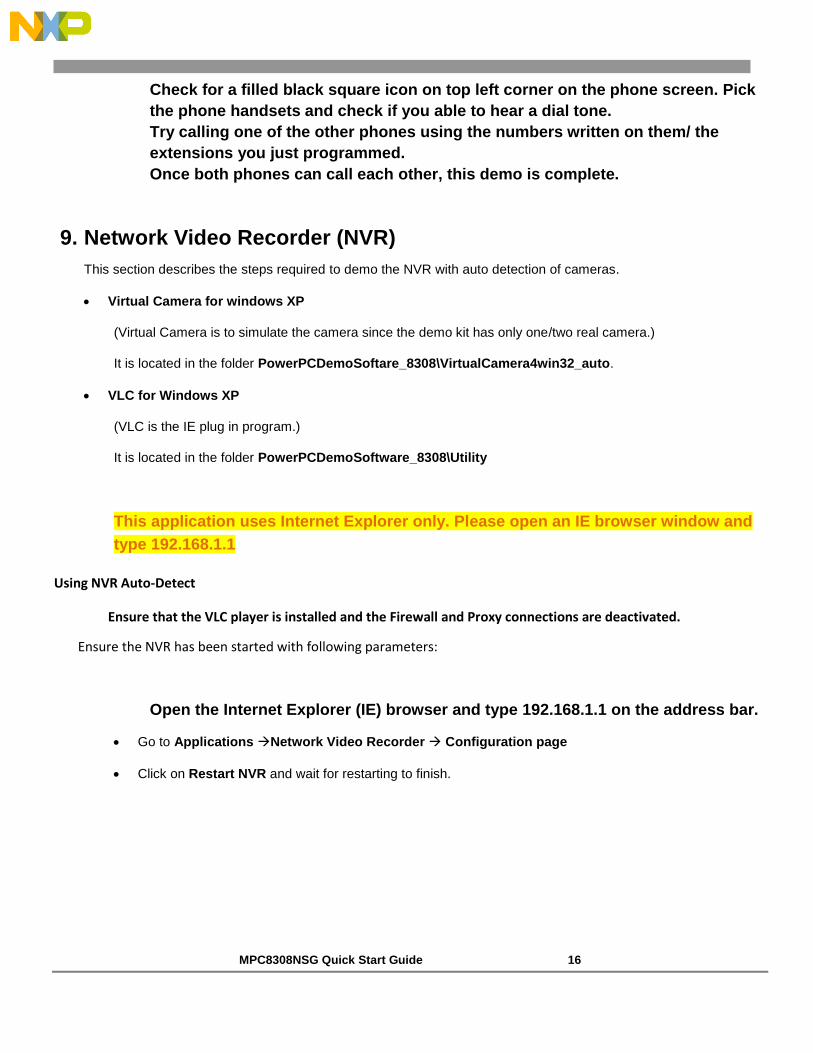
Check for a filled black square icon on top left corner on the phone screen. Pick
the phone handsets and check if you able to hear a dial tone.
Try calling one of the other phones using the numbers written on them/ the
extensions you just programmed.
Once both phones can call each other, this demo is complete.
9. Network Video Recorder (NVR)
This section describes the steps required to demo the NVR with auto detection of cameras.
Virtual Camera for windows XP
(Virtual Camera is to simulate the camera since the demo kit has only one/two real camera.)
It is located in the folder PowerPCDemoSoftare_8308\VirtualCamera4win32_auto.
VLC for Windows XP
(VLC is the IE plug in program.)
It is located in the folder PowerPCDemoSoftware_8308\Utility
This application uses Internet Explorer only. Please open an IE browser window and
type 192.168.1.1
Using NVR Auto-Detect
Ensure that the VLC player is installed and the Firewall and Proxy connections are deactivated.
Ensure the NVR has been started with following parameters:
Open the Internet Explorer (IE) browser and type 192.168.1.1 on the address bar.
Go to Applications Network Video Recorder Configuration page
Click on Restart NVR and wait for restarting to finish.
MPC8308NSG Quick Start Guide 17
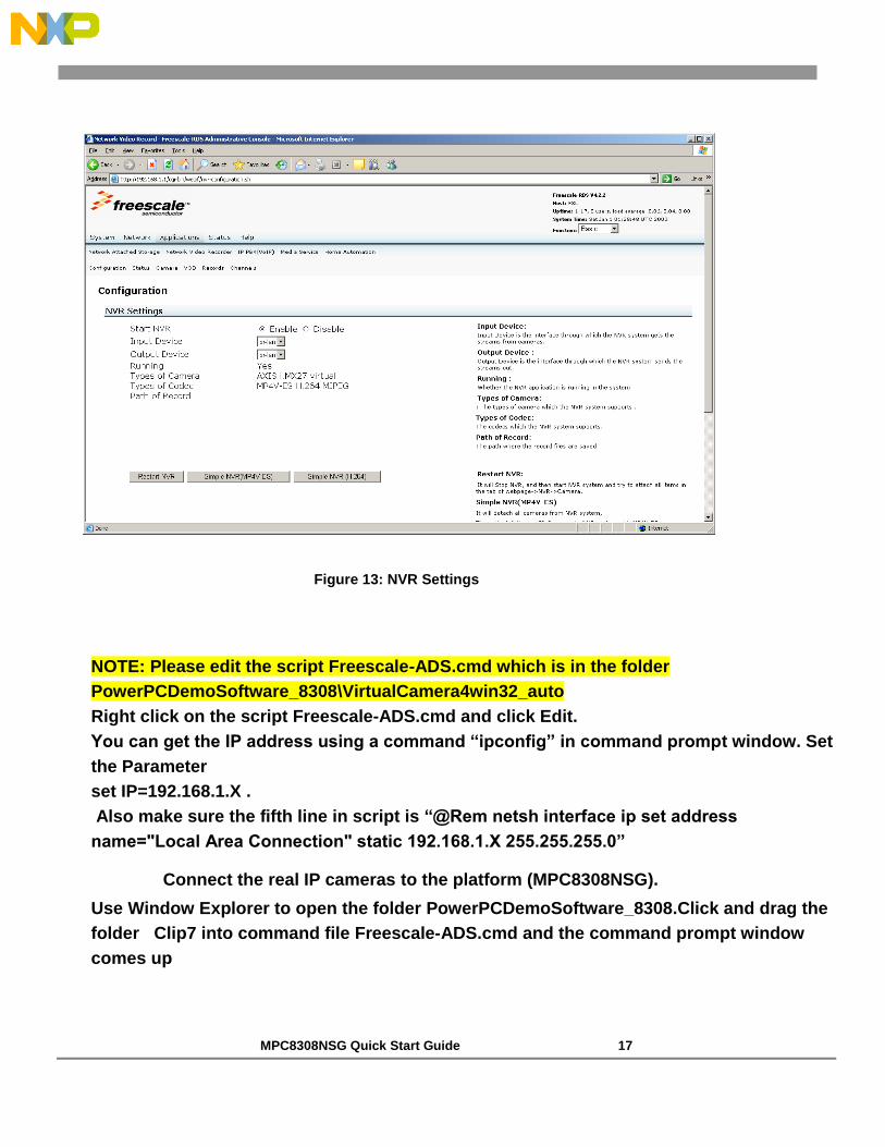
Figure 13: NVR Settings
NOTE: Please edit the script Freescale-ADS.cmd which is in the folder
PowerPCDemoSoftware_8308\VirtualCamera4win32_auto
Right click on the script Freescale-ADS.cmd and click Edit.
You can get the IP address using a command “ipconfig” in command prompt window. Set
the Parameter
set IP=192.168.1.X .
Also make sure the fifth line in script is “@Rem netsh interface ip set address
name="Local Area Connection" static 192.168.1.X 255.255.255.0”
Connect the real IP cameras to the platform (MPC8308NSG).
Use Window Explorer to open the folder PowerPCDemoSoftware_8308.Click and drag the
folder Clip7 into command file Freescale-ADS.cmd and the command prompt window
comes up
MPC8308NSG Quick Start Guide 18
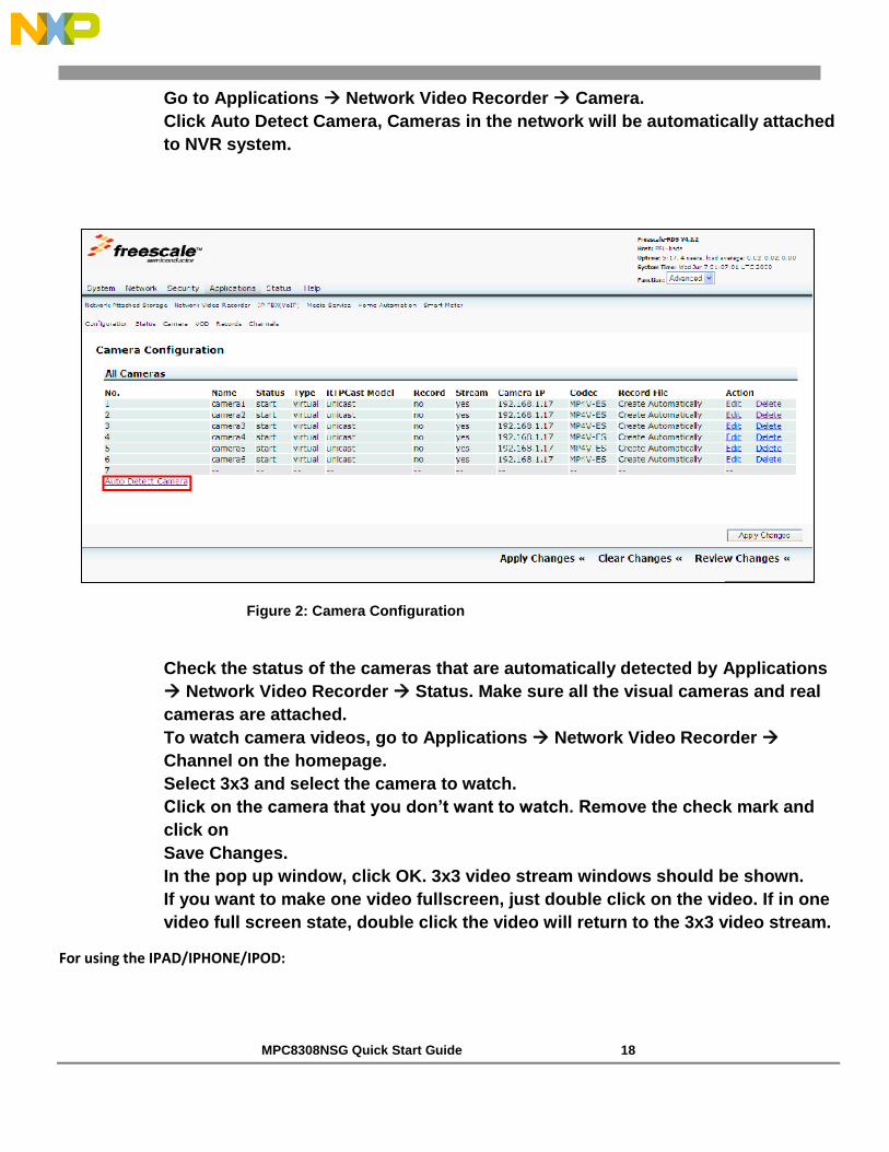
Go to Applications Network Video Recorder Camera.
Click Auto Detect Camera, Cameras in the network will be automatically attached
to NVR system.
Figure 2: Camera Configuration
Check the status of the cameras that are automatically detected by Applications
Network Video Recorder Status. Make sure all the visual cameras and real
cameras are attached.
To watch camera videos, go to Applications Network Video Recorder
Channel on the homepage.
Select 3x3 and select the camera to watch.
Click on the camera that you don’t want to watch. Remove the check mark and
click on
Save Changes.
In the pop up window, click OK. 3x3 video stream windows should be shown.
If you want to make one video fullscreen, just double click on the video. If in one
video full screen state, double click the video will return to the 3x3 video stream.
For using the IPAD/IPHONE/IPOD:

MPC8308NSG Quick Start Guide 19
Go to Settings select the WiFi
Go to “Streamer” application and select the address of the visual camera you
want to view
Go to Safari and type in the IP address taped on the live camera. This live camera
has an IP address 192.168.1.x
Note: If you do not know the IP addresses then go to Network Vedio Recorder-
>Camera to view the IP address in “Camera IP ” column
MPC8308 NVR performance data
Input Streams Total Channels Total Bit Rate
D1/mp4v/30fps/1mbps 36 36 Mbps
D1/mp4v/30fps/3mbps 12 36 Mbps
HD - 1080p/mp4v/30fps/10mbps 3 30 Mbps
D1/H.264/30fps/1mbps 36 36 Mbps
D1/H.264/30fps/3mbps 12 36 Mbps
Appendix A
To start DLNA:
1. Install the Teraterm VT from the download software.

MPC8308NSG Quick Start Guide 20
2. Configure the Teraterm with 115200-8-N-1.
3. In the TeraTerm command terminal, type the following commands:
cd /tmp
mkdir shares
mount -t msdos /dev/sda1 /tmp/shares
4. Open the IE browser and type 192.168.1.1; it will open the device homepage.
5. On the homepage, go to: Applications Media Service DLNA.
6. Disable DLNA (select the Disable radio button) Save Changes Apply Changes.
7. Enable DLNA (select the Enable radio button) Save Changes Apply Changes.
Figure 19: DLNA Configuration

MPC8308NSG Quick Start Guide 21
Appendix B
This section describes the steps required to demonstrate the VoIP capability of the Reference Platform using
multimedia IP phones.
1. Follow the basic setup instruction as described in VoIP section (Page 16).
2. Set up the multimedia IP phones in similar way as regular IP phones by following the steps 2 – 6 on page 17.
3. Calling from one multimedia IP phone to the other multimedia IP phone
a. Check for the dial tone on the phones.
b. Press the line selection button and then press F2 to select line 2 (shown in figure below).
c. Enter the extension number of the other phone and press Call button.
Figure 20: VOIP setup
Once both phones are able to call each other, the demo is complete.
Line
selection Line 2