mp1570a - xenyasup.xenya.si/sup/info/anritsu/mp1570a/mp1570a_ei1200.pdf · mp1570a...
TRANSCRIPT

PRODUCT INTRODUCTION
MP1570ASONET/SDH/PDH/ATM Analyzer
ANRITSU CORPORATION
MEASUREMENT SOLUTIONS

CONFIDENTIAL 1
Copyright 2001 by ANRITSU CORPORATIONThe contents of this manual shall not be disclosed in any way orreproduced in any media without the express written permission ofAnritsu Corporation.

1
The MP1570A has been developedmainly for evaluating and maintainingPDH/SDH transmission equipment; itssingle-cabinet, portable constructionmakes it perfect as a PDH/SDH/ATManalyzer. Although the functions andperformance of the MP1552B have beenupgraded in the new MP1570A, it is stillcompatible with the older SDH plug-inunits (both optical and electrical) for ex-cellent cost performance.
Your Global Partner for the 21st CenturyYour Global Partner for the 21st CenturyYour Global Partner for the 21st CenturyYour Global Partner for the 21st Century1570-1
MP1570ASONET/SDH/PDH/ATM
Analyzer
Anritsu CorporationMeasurement Solutions
Your Global Partner for the 21st CenturyYour Global Partner for the 21st CenturyYour Global Partner for the 21st CenturyYour Global Partner for the 21st Century1570-2
External View of MP1570A

2
This shows the features of theMP1570A.
The MP1570A configuration can be se-lected from a full lineup of functionsplus three new types of optical interfaceunit.It is an extremely cost effective meas-uring instrument because it can also useexisting MP1552B interface units.
Your Global Partner for the 21st CenturyYour Global Partner for the 21st CenturyYour Global Partner for the 21st CenturyYour Global Partner for the 21st Century1570-3
Plug-in Unit Method
Supports SDH/SONET & PDH Tests
Simple Operation
Software Upgrade
Built-in Printer and FDD
Plug-in Construction
Useful Features
Other Functions
Features
Your Global Partner for the 21st CenturyYour Global Partner for the 21st CenturyYour Global Partner for the 21st CenturyYour Global Partner for the 21st Century1570-4
– Full Line of Interface Units✦ Optical 1.31, 1.55, 1.31/1.55
✦ Electrical NRZ, CMI
– Optical Units with Built-in Power Meter
Plug-In Unit Method
✦Optical 156/622M (1.31) MP0111A✦Optical 156/622M (1.55) MP0112A✦Optical 156/622M (1.31/1.55) MP0113A ✦CMI MP0105A✦NRZ (156M/622M) MP0108A

3
The MP1570A uses a plug-in methodproviding customers with flexible con-figuration options for various applica-tions.The units in red italics shown above arenew units (for 2.5G).
Not only can the MP1570A plug-in unitsbe changed, but one instrument covers awide range including SDH/SONETmapping and PDH. Of course, bothout-of-service and in-service measure-ment are possible.
Your Global Partner for the 21st CenturyYour Global Partner for the 21st CenturyYour Global Partner for the 21st CenturyYour Global Partner for the 21st Century1570-5
Interface Units✦2.5/10G MU150000A✦Optical 10G Tx MU150001A/B✦Optical 10G Rx MU150002A✦2.5G MU150008A/150009A/150010A✦2/8/34/139/156M MP0121A✦1.5/45/52M MP0122A/B
✦ATM MP0123A✦Jitter/Wander
•2/8/34/139M,156/622M MP0124A•1.5/45M,52/156/622M MP0125A•2/8/34/139M,1.5/45M, MP0126A
52/156/622M✦2.5G Jitter MP0130A✦Add/Drop MP0131A
− Supports Variety of Measurementsusing Plug-in Units
MP1570A
Plug-in Unit Method
Your Global Partner for the 21st CenturyYour Global Partner for the 21st CenturyYour Global Partner for the 21st CenturyYour Global Partner for the 21st Century1570-6
Supports SDH/SONET &PDH Tests
– In-service monitoring (G.772)
✦ 2.5G,10G
✦ 52M, 156M, 622M (G.703, G.958)
✦ 2M, 8M, 34M, 139M, 1.5M, 45M(G.703)
✦ SDH/SONET PDH Measurement
4
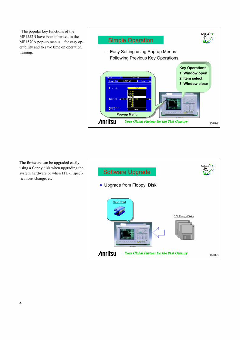
The popular key functions of theMP1552B have been inherited in theMP1570A pop-up menus for easy op-erability and to save time on operationtraining.
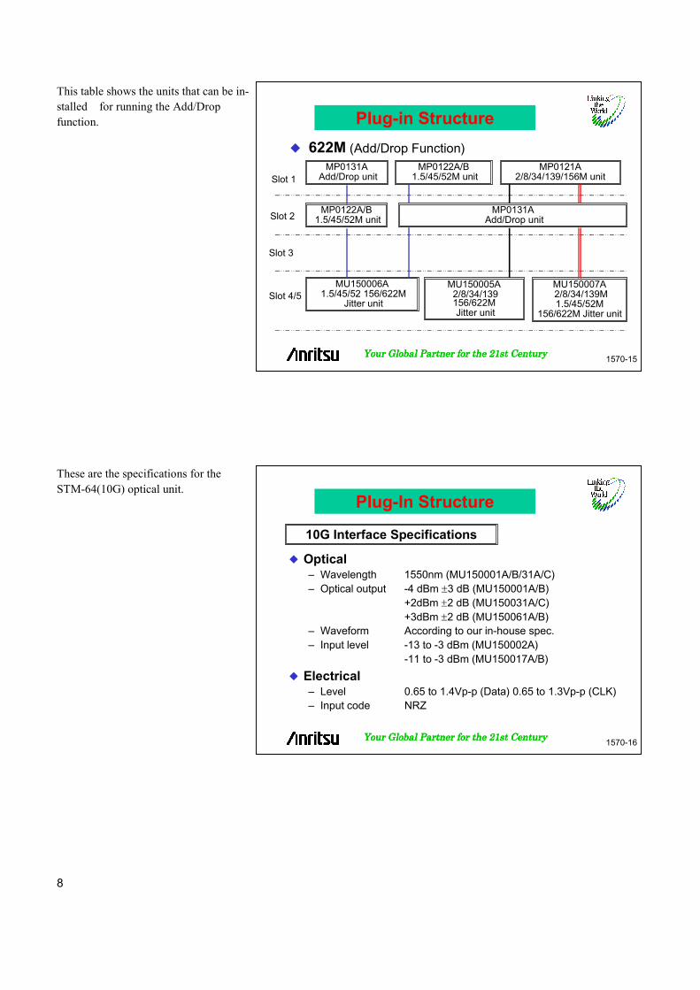
The firmware can be upgraded easilyusing a floppy disk when upgrading thesystem hardware or when ITU-T speci-fications change, etc.
Your Global Partner for the 21st CenturyYour Global Partner for the 21st CenturyYour Global Partner for the 21st CenturyYour Global Partner for the 21st Century1570-7
– Easy Setting using Pop-up Menus
Following Previous Key Operations
Pop-up Menu
Key Operations
1. Window open
2. Item select
3. Window close
Simple Operation
Your Global Partner for the 21st CenturyYour Global Partner for the 21st CenturyYour Global Partner for the 21st CenturyYour Global Partner for the 21st Century1570-8
Upgrade from Floppy Disk
Flash ROM
3.5“ Floppy Disks
Software Upgrade

5
The MP1570A has a built-in printer (topedge) and floppy disk drive (right side)as standard equipment so measurementsettings, results and analysis data can beeither printed out directly or saved todisk and used for later analysis on aMP1570A or a PC (using graphing /spreadsheet software, etc.).
This is a side view of the MP1570A(with 2.5G Add/Drop unit installed).
Your Global Partner for the 21st CenturyYour Global Partner for the 21st CenturyYour Global Partner for the 21st CenturyYour Global Partner for the 21st Century1570-9
– For Recording and Saving MeasurementConditions & Results
Built-in Printer✦Measurement conditions✦Measurement results✦Screen hard copy
Floppy Disk 3.5”
✦Measurement conditions
✦Measurement results
✦Analysis data
✦Screen data (bit map)
Built-in Printer and FDD
Your Global Partner for the 21st CenturyYour Global Partner for the 21st CenturyYour Global Partner for the 21st CenturyYour Global Partner for the 21st Century1570-10
Plug-in Structure
Right Side Cover of MP1570A
Slot 1
Slot 2
Slot 3
Slot 4
Slot 5

6
This table shows the units that can be in-stalled for running the Add/Drop func-tion.
This table shows the units supported upto STM-16 (2488 Mb/s) classified bysystem and application.
Your Global Partner for the 21st CenturyYour Global Partner for the 21st CenturyYour Global Partner for the 21st CenturyYour Global Partner for the 21st Century1570-11
10G
MU150000A 2.5G/10G unit
Slot 2
Slot 3
Slot 4/5
Slot 1
MU150002A Optical 10G Rx (Narrow) unitMU150017A/B Optical 10G Rx (Wide) unit
MP0121A2/8/34/139/156M unit
MP0122A/B 1.5/45/52M unit
MP0131A Add/Drop unit
Plug-in Structure
MU150001A/B Optical 10G Tx (1.55) unitMU150031A/C Optical 10G Tx (1.55) High power unit
MU150061AB Optical 10G (1.31) unit
Your Global Partner for the 21st CenturyYour Global Partner for the 21st CenturyYour Global Partner for the 21st CenturyYour Global Partner for the 21st Century1570-12
2.5GMP0121A
2/8/34/139/156M unitMP0122A/B
1.5/45/52M unit
MU150008/09/10A 2.5G unit
MU150011A 2.5G Jitter unit
MU150005A 2/8/34/139156/622M Jitter unit
MU150006A 1.5/45/52156/622M Jitter unit
MU150007A 2/8/34/139M1.5/45/52M
156/622M Jitter unit
Slot 2
Slot 3
Slot 4/5
Slot 1
Plug-in Structure

7
This table shows the units that can be in-stalled for running the Add/Drop func-tion.
This table shows the units supporting upto STM-4 (622 Mb/s) classified by sys-tem and application.
Your Global Partner for the 21st CenturyYour Global Partner for the 21st CenturyYour Global Partner for the 21st CenturyYour Global Partner for the 21st Century1570-13
MU150011A 2.5G Jitter unit
Slot 2
Slot 3
Slot 4/5
Slot 1
MU150005A 2/8/34/139156/622M Jitter unit
MU150006A 1.5/45/52 156/622M
Jitter unit
MU150007A 2/8/34/139M1.5/45/52M
156/622M Jitter unit
MP0131A Add/Drop unit
MU150008/09/10A 2.5G unit
2.5G (Add/Drop Function)
Plug-in Structure
Your Global Partner for the 21st CenturyYour Global Partner for the 21st CenturyYour Global Partner for the 21st CenturyYour Global Partner for the 21st Century1570-14
622M
MP0121A 2/8/34/139/156M unit
MP0122A/B 1.5/45/52M unit
Slot 2
Slot 3
Slot 4/5
MP0123A ATM unit
MU150006A 2/8/34/139156/622M Jitter unit
MU150007A 1.5/45/52156/622M Jitter unit
MU150005A 2/8/34/139M1.5/45/52M
156/622M Jitter unit
Slot 1
MP0122A/B 1.5/45/52M unit
Plug-in Structure
8
This table shows the units that can be in-stalled for running the Add/Dropfunction.
These are the specifications for theSTM-64(10G) optical unit.
Your Global Partner for the 21st CenturyYour Global Partner for the 21st CenturyYour Global Partner for the 21st CenturyYour Global Partner for the 21st Century1570-15
MP0121A2/8/34/139/156M unit
MP0122A/B 1.5/45/52M unit
MU150005A 2/8/34/139156/622M Jitter unit
MU150006A 1.5/45/52 156/622M
Jitter unit
MU150007A 2/8/34/139M1.5/45/52M
156/622M Jitter unit
MP0131A Add/Drop unit
MP0122A/B 1.5/45/52M unit
MP0131A Add/Drop unitSlot 2
Slot 3
Slot 4/5
Slot 1
622M (Add/Drop Function)
Plug-in Structure
Your Global Partner for the 21st CenturyYour Global Partner for the 21st CenturyYour Global Partner for the 21st CenturyYour Global Partner for the 21st Century1570-16
Optical– Wavelength 1550nm (MU150001A/B/31A/C)– Optical output -4 dBm ±3 dB (MU150001A/B)
+2dBm ±2 dB (MU150031A/C)+3dBm ±2 dB (MU150061A/B)
– Waveform According to our in-house spec.– Input level -13 to -3 dBm (MU150002A) -11 to -3 dBm (MU150017A/B)
Electrical– Level 0.65 to 1.4Vp-p (Data) 0.65 to 1.3Vp-p (CLK)– Input code NRZ
10G Interface Specifications
Plug-In Structure

9
These are the specifications for theSTM-16(2.5 G) optical unit.
This table shows the functional featuresof the MP1570A.
Your Global Partner for the 21st CenturyYour Global Partner for the 21st CenturyYour Global Partner for the 21st CenturyYour Global Partner for the 21st Century1570-17
Optical– Wavelength 1310, 1550, 1310/1550 nm– Optical output -4 dBm ± 3 dB– Waveform ITU-T G.957– Input level -28 to -9 dBm (MU150008A/150009A/150010A)
Electrical– Level ECL (send/receive)
– Monitor input NRZ (clock recovery)
2.5G Interface Specifications
Plug-in Structure
Your Global Partner for the 21st CenturyYour Global Partner for the 21st CenturyYour Global Partner for the 21st CenturyYour Global Partner for the 21st Century1570-18
All SDH/SONET Mappings Supported
Concatenation Mapping
SONET/ITU-T Compliance Tests
Full Through Mode Functions
Error Performance Analysis
Automatic Trouble Search
SDH/SONET Pointer Generation
PDH MUX/DEMUX Function (Option)
Jitter/Wander Generation/Measurement at all Bit Rates
ATM Pattern Generation/Measurement
Auto-setup
Functional Features

10
This shows the mapping of theMP1570A.
By installing an Add/Drop unit, a PDHsignal can either be added to or droppedfrom an SDH signal.
Your Global Partner for the 21st CenturyYour Global Partner for the 21st CenturyYour Global Partner for the 21st CenturyYour Global Partner for the 21st Century1570-19
AUG AU-4 VC-4
STM-4TUG-3 TU-3 VC-3
TUG-2 TU-2 VC-2
AU-3 VC-3STM-0
STM-1
X3
X7
X3
STM-16X4
X16
*1: MP0121A required*2: Japan mapping (option 09) required*3: MP0122A/B required*4: MU150000A required*5: MU150000A or MU150008/09/10A required
X64STM-64
*1
* 1
* 1
* 1
* 3X7
139M (Async)Bulk
34M (Async)34M (Sync)45M (Async)Bulk
Bulk6M (Async)6M (Bitsync F)mc
TU-12 VC-12X3
X4
* 1
* 1
* 1
* 1
* 1
* 1
2M (Async)2M (Bitsync F)2M (Bitsync L)2M (Bytesync F)2M (Bytesync L)Bulk
TU-11 VC-11
* 2* 2* 2 * 2
1.5M (Async)1.5M (Bitsync F)1.5M (Bitsync L)1.5M (Bytesync F)1.5M (Bytesync L)Bulk384k (Data)384k (Voice)Byte (Data)Byte (Voice)
All SDH/SONET Mappings Supported
Your Global Partner for the 21st CenturyYour Global Partner for the 21st CenturyYour Global Partner for the 21st CenturyYour Global Partner for the 21st Century1570-20
Add/Drop
AUG AU-4 VC-4
STM-4
139 M (Async)
TUG-3 TU-3 VC-3
TUG-2
AU-3 VC-3
TU-12 VC-12
TU-11 VC-11
STM-0
STM-134M (Async)
45M (Async)
2 M (Async)
1.5M (Async)
X3
X7
X4
STM-64
Add/Drop Interface
STM-16
X3
All SDH/SONET Mappings Supported
X4
11
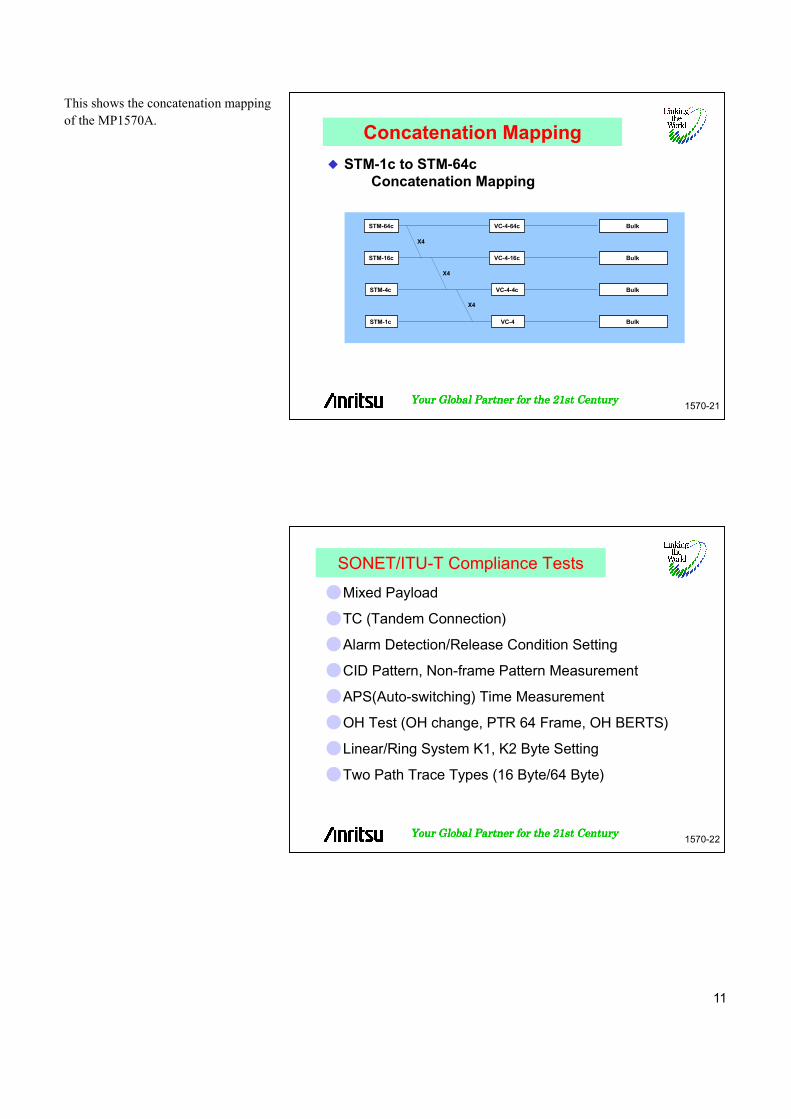
This shows the concatenation mappingof the MP1570A.
Your Global Partner for the 21st CenturyYour Global Partner for the 21st CenturyYour Global Partner for the 21st CenturyYour Global Partner for the 21st Century1570-21
STM-64c
STM-16c
STM-4c
STM-1c
VC-4-4c
VC-4
X4
Bulk VC-4-64c
X4
X4
VC-4-16c Bulk
Bulk
Bulk
STM-1c to STM-64cConcatenation Mapping
Concatenation Mapping
Your Global Partner for the 21st CenturyYour Global Partner for the 21st CenturyYour Global Partner for the 21st CenturyYour Global Partner for the 21st Century1570-22
SONET/ITU-T Compliance Tests
Mixed Payload
TC (Tandem Connection)
Alarm Detection/Release Condition Setting
CID Pattern, Non-frame Pattern Measurement
APS(Auto-switching) Time Measurement
OH Test (OH change, PTR 64 Frame, OH BERTS)
Linear/Ring System K1, K2 Byte Setting
Two Path Trace Types (16 Byte/64 Byte)

12
POH N1,N2 bytes can be set.Errors/Alarms can be measured at tan-dem connection.
Your Global Partner for the 21st CenturyYour Global Partner for the 21st CenturyYour Global Partner for the 21st CenturyYour Global Partner for the 21st Century1570-23
TUG3 TU-3 VC-3 34M
TUG3
TUG3
TUG2
TUG2
TU-2 VC-2 BULK
TU-12 VC-12 BULK
Measured channel
Other channel 1
Other channel 2
VC-4STM-1
Mixed PayloadAt mapping measurement below TUG3, able to set two otherchannels in addition to measurement target channel
SONET/ITU-T Compliance Tests
Your Global Partner for the 21st CenturyYour Global Partner for the 21st CenturyYour Global Partner for the 21st CenturyYour Global Partner for the 21st Century1570-24
Tandem Connection– Able to set and measure N1 and N2 bytes
SONET/ITU-T Compliance Tests

13
The MP1570A can change alarm detec-tion /release condition setting(except LOS, OOF and TIM).
The MP1570A can edit program andcapture measurement datato measure APS switching time.This measurement complies to ITU-TRec. G.783 and G.841.
Your Global Partner for the 21st CenturyYour Global Partner for the 21st CenturyYour Global Partner for the 21st CenturyYour Global Partner for the 21st Century1570-25
Alarm Detection/Release Condition SettingSet
detection/releasetimes
SONET/ITU-T Compliance Tests
Your Global Partner for the 21st CenturyYour Global Partner for the 21st CenturyYour Global Partner for the 21st CenturyYour Global Partner for the 21st Century1570-26
APS (Auto-switching) Time Setting
Switch time
Data setting
Capture
SONET/ITU-T Compliance Tests

14
For SDH, the defaults can be set for theSOH/POH bytes except the parity andK1/K2 bytes. In addition, section andpath trace can also be set.For PDH, the overhead can be set incompliance with ITU-T Rec. G.704 andG.832.
Your Global Partner for the 21st CenturyYour Global Partner for the 21st CenturyYour Global Partner for the 21st CenturyYour Global Partner for the 21st Century1570-27
OH TestAble to select and test overhead type (OH change,PTR64 frame, OH BERTS, OH Add/Drop)
SONET/ITU-T Compliance Tests
Your Global Partner for the 21st CenturyYour Global Partner for the 21st CenturyYour Global Partner for the 21st CenturyYour Global Partner for the 21st Century1570-28
Linear/Ring System K1 and K2 Byte Setting
Protocol selection
Mnemonic setting
G.841
G.783
SONET/ITU-T Compliance Tests

15
Setting/Monitoring of section trace andpath trace (J0, J1 and J2)can also be possible.
Your Global Partner for the 21st CenturyYour Global Partner for the 21st CenturyYour Global Partner for the 21st CenturyYour Global Partner for the 21st Century1570-29
Two Path Trace Types (16 Byte/64 Byte)
Trace pattern setting
Trace pattern monitoring
SONET/ITU-T Compliance Tests
Your Global Partner for the 21st CenturyYour Global Partner for the 21st CenturyYour Global Partner for the 21st CenturyYour Global Partner for the 21st Century1570-30
1.Transparent
2. OH Overwrite
3. Payload Overwrite
4. Add/Drop
Rx
Tx
Rx
Tx
Rx
Tx
External
DS1,DS3,PDH
Test signal (internal) Add/DropVC-4, VC-2, VC-12, VC-11 signals
External signal Add/DropDS1, DS3, PDH signals
SOH, POH ChangeError/Alarm Add
In-service monitoring
Full Through Mode Functions
Four Through Modes (~STM-64/OC-192)

16
Performance can be measured both in-service and out-of-service in accordancewith G.821, G.826, M2100 and M2101.Moreover, measurements for G.821analysis can be performed either incompliance or not in compliance withAnnex-D.
The trouble search function automati-cally measures all channels (tributaries)of input signals set at the setting screen.If an error or alarm is detected duringmeasurement, it is displayed on theanalyze screen and the channel with thetrouble can be examined manually whenmeasurement is finished.By installing the MUX/DEMUX func-tion (option), all channels from N x 64 Kto 622M (7860 channels—CEPT sys-tem) can be measured automatically,which demonstrates its usefulness bygreatly shortening the measurementperiod at circuit installation, etc.
Your Global Partner for the 21st CenturyYour Global Partner for the 21st CenturyYour Global Partner for the 21st CenturyYour Global Partner for the 21st Century1570-31
Both In-service & Out-of-service
G.821 ANNEX-D or G.821
Type Error Parameter
G.821 Bit, FAS, Code EC, ES, EFS, SES, DM, US,
Code ES
M.2100 Bit, FAS or CRC-4 or
Parity or CRC-6, E-bit
ES, SES, US
G.826 Bit, FAS or CRC-4 or
Parity or CRC-6, BIP, REI
ES, SES, BBE, ESR, SESR,
BBER, SDP, US
M.2101 BIP, REI ES, SES, US
M.2110
M.2120
Same as M.2100, M2101 ES, SES, US (2-hour, 24-hour, 7-day)
TR1-ES, TR1-SES, TR2-ES, TR2-SES, ES, SES, US
Same as M.2100, M2101
Error Performance Analysis
Your Global Partner for the 21st CenturyYour Global Partner for the 21st CenturyYour Global Partner for the 21st CenturyYour Global Partner for the 21st Century1570-32
Auto-setting of All Channels
Measurement up to N x 64 Kb/sPDH channel by addition ofMUX/DEMUX
Analyze Screen
Confirm trouble contents ofchannel
Measurement Results Screen
Confirm measurement results ofall channels
Automatic Trouble Search

17
The MP1570A can perform four pointersequence tests satisfying ITU-T G.783.Moreover, it can also perform three 87:3pointer sequence tests to give a total ofseven tests in all.
When the MUX/DEMUX function (op-tion) is added, measurement can be per-formed from N x 64K to SDH for eachof the Japanese, European and N.American systems.Moreover, error/alarm addition can beperformed for the selected tributary forevaluation testing of transmissionequipment.
Your Global Partner for the 21st CenturyYour Global Partner for the 21st CenturyYour Global Partner for the 21st CenturyYour Global Partner for the 21st Century1570-33
Compliance with ITU-T G.783
– Combined jitter measurement
Test sequence Poi nt er adj ust ment event - t i me di agram Paramet er
Si ngl e of opposi t epol ar i t y
T1T1: 10 s
Regul ar wi t h doubl e T2 T3T2: 0. 75s
(C11, C12)T1 34ms
(C3, C4)Regul ar wi t h mi ssi ng T2 mi ssi ng
T3: 2ms(C11, C12)
T1 0. 5ms(C3, C4)
Doubl e of opposi t e T3pol ar i t y
T1
87-3/ 26-1 normal 87 or 26 3 or 1
T Cancel T: 1s(C11, C12)
87-3/ 26-1 addi t i onal Add 34ms43 or 13 43 or 12 3 or 1 (C3, C4)
t : 2msT t Cancel (C11, C12)
0. 5ms87-3/ 26-1 cancel 86 or 25 4 or 1 (C3, C4)
T Cancel
SDH/SONET Pointer Generation
Your Global Partner for the 21st CenturyYour Global Partner for the 21st CenturyYour Global Partner for the 21st CenturyYour Global Partner for the 21st Century1570-34
Signal Generation and Measurementup to N x 64 Kb/s
✦Add/Drop error/alarm at set tributary
✦Simultaneous error/alarm detection for set channel
1. EC 2. USA
✦ MP0121A 2/8/34/139/156M unit
64k64k 2M2M 8M8M 34M34M 139M139M 156M156M 622M622M
64k64k
64k64k
Dummy Dummy Dummy Dummy
1
2
30/31
ch
(SDH layer)
✦ MP0122A 1.5/45/52M unit
64k64k 1.5M1.5M 45M45M 156M156M 622M622M
64k64k
64k64k
Dummy Dummy Dummy
1
2
24
ch
(SDH layer)
28
32
1
4
PDH MUX/DEMUX Function (Option)

18
The same testing is also possible for in-ternational mappings.
Your Global Partner for the 21st CenturyYour Global Partner for the 21st CenturyYour Global Partner for the 21st CenturyYour Global Partner for the 21st Century1570-35
Signal Generation and Measurementup to N x 64 Kb/s
Dummy
45M45M
Dummy
64k64k 2M2M
64k64k
64k64k
Dummy
1
2
30/31
(SDH layer)
64k64k 1.5M1.5M
64k64k
64k64k
Dummy
1
2
24
ch
28
32
1
4
156M156M 622M622M
21
32
1
4
45M-2M option
3. International Mapping System (45M~2M)
✦ MP0122A 1.5/45/52M unit
✦ MP0121A 2/8/34/139/156Munit required
PDH MUX/DEMUX Function (Option)
Your Global Partner for the 21st CenturyYour Global Partner for the 21st CenturyYour Global Partner for the 21st CenturyYour Global Partner for the 21st Century
Jitter/Wander Generation/Measurement at all BitRates
ME3630A+MP1777A+MP9677BMS4630B+PC (MX177701A)
MS4630BAnritsu
AnritsuAnritsu
Anritsu
AnritsuAnritsu
MP9657C
E/O
Anritsu
MP1777A
MS4630B
MP9677B
ME3630ARX
ME3630ATX
MP1570A / MP1580A

19
These are the jitter specifications forSTM-16 (2.5G).
These are the STM-16 (2.5G) wanderspecifications.
Your Global Partner for the 21st CenturyYour Global Partner for the 21st CenturyYour Global Partner for the 21st CenturyYour Global Partner for the 21st Century1570-37
Jitter Generation– Modulation frequency 0.1 Hz~20 MHz
– Amplitude 0 to 808 UIp-p
– Jitter tolerance ITU-T G.825,G.958 A,G.958 B, User
– Offset ± 70.0 ppm/0.1 ppm
Jitter Measurement– Units UI p-p, UI+p, UI-p/UI rms (opt-01)
– Measurement range 2UI 0.000 to 2.020 UIp-p
32UI 0.00 to 32.20 UIp-p
– Ref. signal Internal/External
– Jitter transfer char. ITU-T G.958 A,G.958 B, User
MU150011A 2.5G Jitter Unit
Jitter/Wander Generation/Measurement at all BitRates
Your Global Partner for the 21st CenturyYour Global Partner for the 21st CenturyYour Global Partner for the 21st CenturyYour Global Partner for the 21st Century1570-38
Wander Generation– Frequency 10 µHz~0.2 Hz– Amplitude 0 to 57600 UIp-p/10 step
UIp-pWander Measurement– Same as MU150005A/MU150006A/MU150007A
option 02
MU150011A 2.5G Jitter Unit
Jitter/Wander Generation/Measurement at all BitRates

20
Wander measurement (option) can beperformed by adding the relevant option.Measurement can be performed at all bitrates of 1.5M, 2M, 8M, 34M,45M,139M, 52M, 156M, 622M and2488M.There are four measurement units:Peak-to-Peak, +Peak, -Peak and TIE.
Frequency offset and measurement canbe performed by installing a jitter gen-eration/measurement module.Frequency offset can be measured at ei-ther jitter ON or jitter OFF.The frequency of the signal input fromthe connector is measured with a resolu-tion of 0.1 ppm in units of either ppm orHz.
Your Global Partner for the 21st CenturyYour Global Partner for the 21st CenturyYour Global Partner for the 21st CenturyYour Global Partner for the 21st Century1570-39
Wander Measurement (option) (Rec. O.172)
– Measurement UnitsPeak-to-Peak, +Peak/-Peak, TIEResolution 0.5 ns
– FilterDC to 0.01 Hz, DC to 10 Hz, 0.01 to 10 Hz
– Reference Clock2 Mb/s (HDB3), 2 MHz, 1.5 Mb/s (AMI/B8ZS), 1.5 MHz
– MTIE/TDEV MX150001B Software (host PC)
Jitter/Wander Generation/Measurement at all BitRates
Your Global Partner for the 21st CenturyYour Global Partner for the 21st CenturyYour Global Partner for the 21st CenturyYour Global Partner for the 21st Century1570-40
Frequency Offset
Frequency Offset at Jitter Generation
– Two offset ranges
± 999.9 ppm/0.1 step (jitter off)
± 70.0 ppm/0.1 step (jitter on)
– Accuracy 0.1 ppm
– Resolution 0.1ppm
– Display Hz or ppm
Frequency Measurement
Jitter/Wander Generation/Measurement at all BitRates

21
The MP1570A can generate jitter signalsthat comply with the ITU-T O.171 rec-ommendation. Any of five jitter am-plitude ranges can be selected: 2, 20,50, 200 and 800 UIp-p.The jitter frequency covers a wide rangefrom 0.1 Hz~20 MHz.
Jitter can also be measured in compli-ance with ITU-T O.171.The jitter amplitude can be measured intwo ranges; the maximum range is 20(~622M)/32 UIp-p (2488M)The jitter measurement frequency is 2Hz~20 MHz, and the measurement unitscan be selected from Peak-to-Peak,+Peak/-Peak, RMS (option) and HitCount.
Your Global Partner for the 21st CenturyYour Global Partner for the 21st CenturyYour Global Partner for the 21st CenturyYour Global Partner for the 21st Century1570-41
52.5/202/808 50/200/800UI(156M/622M/2.5G) range-20dB/decade
20.2 20UI range-20dB/decade
Amplitude[UIpp] 2.02 2UI range
-20dB/decade0.5
0.2
F1 F1' F2 F2' F3 F4 F5 F6Frequency[Hz]
Bit rate F1 F1' FFFF2222****1111
FFFF2222''''****1111
FFFF3333****1111
FFFF4444****1111
FFFF5555****1111
FFFF6666****1111 Remarks
[Mb/s] [Hz] [Hz] [kHz] [kHz] [kHz] [kHz] [kHz] [kHz]1.544 0.1 ---- 0.125 ---- 8 12.5 50 ----2.048 0.1 ---- 1 ---- 20 27.5 110 ----8.448 0.1 ---- 2 ---- 20 105 420 ----
34.368 0.1 ---- 5 ---- 100 250 1,000 ----44.736 0.1 ---- 12.5 ---- 100 250 1,000 ----
139.264 0.1 ---- 5 ---- 100 1,000 4,000 ----51.84 0.1 ---- 2 ---- 80 50 ---- 500
155.52 0.1 1,000 6.5 26 500 150 ---- 1,500622.08 0.1 500 25 50 500 600 ---- 6,000
2488.32 0.1 30 25 12 500 2,000 ---- 20,000****1111 :Typical value
Range✦ 2UI✦ 20UI✦ 50UI (156M) or
200UI (622M) or
800UI (2.5G)
Type✦Manual✦Auto amplitude
Jitter Generation
Jitter/Wander Generation/Measurement at all BitRates
Your Global Partner for the 21st CenturyYour Global Partner for the 21st CenturyYour Global Partner for the 21st CenturyYour Global Partner for the 21st Century1570-42
Bit rate A1 F1 F1' F2 F3 F4 F5 Remarks[Mb/s] UIp-p [Hz] [Hz] [Hz] [kHz] [kHz] [kHz]
1.544 0.5 2 20 200 - 10 402.048 0.5 2 20 450 - 25 1008.448 0.5 2 20 200 - 100 400
34.368 0.5 2 20 500 - 500 80044.736 0.5 2 20 3k - 200 400
139.264 0.5 2 20 250 - 1,000 3,50051.84 0.2 2 20 200 400 100 400
155.52 0.2 2 20 700 1,300 500 1,300622.08 0.2 2 20 20k 5,000 2,000 5,000
2488.32 0.2 10 100 6.25k 100 1,000 20,000
Data[UIpp] 20/32UIrange
20.0/32.0Clock
2UIrange2.0
A1
F1 F1' F2 F3 F4 F5Frequency[Hz]
Jitter Measurement
Measurement units✦ Peak-to-Peak✦ +Peak/-Peak✦ Hit count✦ RMS (optional)
Jitter/Wander Generation/Measurement at all BitRates

22
By adding a jitter genera-tion/measurement module, not only cana jitter signal be generated and measured,but a wander signal (option) can also begenerated too in compliance with theITU-T O.171 recommendations like thejitter signal.
Installing the MP0123A ATM unit per-mits generation and measurement of thefollowing ATM signals:2, 34, 139, 156M (with MP0121A2/8/34/139/156M unit), 1.5, 45, 52M(with MP0122A 1.5/45/52M unit) and156, 622M (withMP0111A/0112A/0113A Optical unit).
Your Global Partner for the 21st CenturyYour Global Partner for the 21st CenturyYour Global Partner for the 21st CenturyYour Global Partner for the 21st Century1570-43
Wander Generation
A 0
A 1
A 2
f0 f1 f2 f3 f4 f5F re q u e n cy [H z ]
Bit rate Amplitude[UIp-p] Frequency[Hz]Remarks
[Mb/s] A0 AAAA1111 AAAA2222 f0 f1 f2 f3 f4 f51.544 - 40 20 - - 10u 50m 0.1 0.22.048 - 40 20 - - 10u 50m 0.1 0.28.448 - 200 20 - - 10u 10m 0.1 0.2
34.368 1,000 110 20 10u 180u 1.6m 16m 0.1 0.244.736 1,200 130 20 10u 180u 1.6m 16m 0.1 0.2
139.264 3,400 380 50 10u 180u 1.6m 16m 0.1 0.251.84 1,200 130 20 10u 180u 1.6m 16m 0.1 0.2
155.52 3,600 400 50 10u 180u 1.6m 16m 0.1 0.2622.08 11114444,,,,444400000000 1,600 200 10u 180u 1.6m 16m 0.1 0.2
2488.32 55557777,,,,666600000000 6,480 800 10u 180u 1.6m 16m 0.13 0.2
Jitter/Wander Generation/Measurement at all BitRates
Your Global Partner for the 21st CenturyYour Global Partner for the 21st CenturyYour Global Partner for the 21st CenturyYour Global Partner for the 21st Century1570-44
(1) ATM Mapping
ATM Pattern Generation & Measurement
ConvergenceSDH (G.708) AAL1
PDH (G.804)
STM4 OPT
STM1 OPT
STM1
STM0
140M(G.832)
34M(G.832)
2M(G.704)
4.5M(G.704)
1.5M(G.704)
Cells ATM/ALL
AAL2
AAL3/4
AAL5
ATM

23
Various types such as CBR and burst canbe used as the traffic pattern at cellsending and three types of settingmethod: cell/s, Kb/s and %, can beused. When burst or sawtooth is se-lected, the setting conditions are easy-to-understand because the send method isdisplayed on the screen.In addition, 10 patterns can be edited asthe background cell.Each can be sent in the range of 0% to100%. (The upper limit depends on theDistribution setting.)
Each type of cell data can be edited.The 65535 byte data of the AAL3/4 andAAL5 payload pattern can be edited onthe screen or externally edited data canbe read from floppy disk.Edited 2016 cell data (header and pay-load) can be sent as memorized cells.Furthermore, the 2106 cell data receivedby using the receive capture function canalso be sent.
Your Global Partner for the 21st CenturyYour Global Partner for the 21st CenturyYour Global Partner for the 21st CenturyYour Global Partner for the 21st Century1570-45
(2) Traffic
Distribution✦ Mode
CBR, Burst, PCR withCDV, Poisson, Sawtooth
✦TimingSingle, Continuous
✦Unitscell/s, Kb/s, %
ATM Pattern Generation & Measurement
Your Global Partner for the 21st CenturyYour Global Partner for the 21st CenturyYour Global Partner for the 21st CenturyYour Global Partner for the 21st Century1570-46
(3) Cell Editing
– Foreground cell
O.191, AAL1,AAL2, AAL3/4, AAL5
– OAM Cell
AIS, RDI, CC, loopback, PM
– Background cell (10 ch)
– Memorize cell
✦1 to 2016 cell
✦Able to recall data in cell memory
ATM Pattern Generation & Measurement

24
Two delay times can be measured: 1-point CDV (the variance in the receivecell arrival time) and 2-point CDV (therandomness in the time from cell send-ing to receiving).Since 1-point CDV and 2-point CDVmeasurements both have an independentmeasurement structure, measurement isvery easy. In addition, the measure-ment results can be displayed either nu-merically or graphically for easy read-ing.
This function detects the receive signalcondition and sets the MP1570A meas-urement conditions automatically.It can be executed at both out-of-serviceand in-service; at in-service, mappingsand frames can be both detected, but atout-of-service, pattern detection is alsopossible too.However, this function does not detectATM patterns.
Your Global Partner for the 21st CenturyYour Global Partner for the 21st CenturyYour Global Partner for the 21st CenturyYour Global Partner for the 21st Century1570-47
(4) Delay Measurement
– Rx cell deviation 1-point CDV
– Tx & Rx cell deviation 2-point CDV
ATM Pattern Generation & Measurement
Your Global Partner for the 21st CenturyYour Global Partner for the 21st CenturyYour Global Partner for the 21st CenturyYour Global Partner for the 21st Century1570-48
Auto-detection of Input SignalAuto-detection of Input SignalAuto-detection of Input SignalAuto-detection of Input Signal
Measurement Conditions (1)Tx/Rx: Rx Setting onlyTx&Rx: Tx and Rx setting
Measurement Conditions (2)
In-service
Out-of-service
Auto-setup

25
For SDH, the defaults can be set for theSOH/POH bytes except the parity andK1/K2 bytes. In addition, section andpath trace can also be set.For PDH, the overhead can be set incompliance with ITU-T Rec. G.704 andG.832.
Your Global Partner for the 21st CenturyYour Global Partner for the 21st CenturyYour Global Partner for the 21st CenturyYour Global Partner for the 21st Century1570-49
Other Functions
Overhead Setting
Dummy Channel
Signaling Preset (Option 09)
Full Error/Alarm Generation & Measurement
Data Capture
Complete Monitoring Functions
Self Test
Your Global Partner for the 21st CenturyYour Global Partner for the 21st CenturyYour Global Partner for the 21st CenturyYour Global Partner for the 21st Century1570-50
OH Preset− SDH SOH/POH Pattern (inc. path trace pattern)
− PDH E3, E4, DS3 PLCP Pattern (ATM) (inc. trail trace pattern)
Overhead Setting

26
The MP1570A can copy and preset themeasurement channeldata to the dummy channel.
Setting or monitoring the signaling bit(ST1∼ST4) can be performedby installing option 09 in the MP1570A.
Your Global Partner for the 21st CenturyYour Global Partner for the 21st CenturyYour Global Partner for the 21st CenturyYour Global Partner for the 21st Century1570-51
Set OH senddata atdummy
selection
Dummy Channel
Copy: Copy measurement channel setting
Dummy: Dummy preset setting
Your Global Partner for the 21st CenturyYour Global Partner for the 21st CenturyYour Global Partner for the 21st CenturyYour Global Partner for the 21st Century1570-52
Signaling bit (ST1~ST4) setting and monitoring, 8multiframe, 64 multiframe
Signaling Preset (Option09)

27
This shows the error measurement andaddition items.
This shows the alarm measurement andaddition items.For ATM, AIS, RDI and continuitycheck cells supporting F4 and F5 can beadded and measured for OAM testing.
Your Global Partner for the 21st CenturyYour Global Partner for the 21st CenturyYour Global Partner for the 21st CenturyYour Global Partner for the 21st Century1570-53
(1) Error measurement and Add
� Error detectionType Er r or s
PDH Bi t , FAS, CRC- 4, E- bi t , Code, Par i t y, CRC- 6, C- bi t , REISDH Bi t , B1, B2, B3, BI P- 2, MS- REI , HP- REI , LP- REIATM Cel l s Cel l count , Cor r ect abl e HEC, Uncor r ect abl e HEC, Non- conf or mi ng cel l
O. 191 Er r or ed cel l , Lost cel l , Mi si nser t ed cel lAAL1 SAR- PDU count , Lost cel l , SNP, Uncor r ect abl e SNP, PRBS, Wor dAAL2 SAR- PDU count , P, OSF, SN, CPS- packet count , HEC, LI , PRBS, Wor dAAL3/ 4 SAR- PDU count , CRC10, MI D, SN, Di scar ded PDU, Segment t ype, Lengt h, Abor t
CPCS- PDU count , Undel i ver d PDU, CPI , Bt ag/ Et ag mi smat ch, BAsi ze, AL, Lengt h,PRBS, Wor d
AAL5 CPCS- PDU count , Di scar ded PDU, Fr ame si ze, Lengt h, CRC32, Abor t , PRBS, Wor d
PM Lost cel l , Mi si nser t ed cel l , BI PV, SECB
Type Er r or sPDH Bi t al l , Bi t i nf o, FAS, E- bi t , Code, Par i t y, CRC- 6, C- bi t , REISDH Bi t al l , Bi t i nf o, FAS, B1, B2, B3, BI P- 2, MS- REI , HP- REI , LP- REIATM Cel l s HEC, User pr ogr ammabl e
O. 191 Lost cel l , Mi si nser t ed cel l , Er r or ed cel l , SECBAAL1 Lost cel l , SNP, PRBS, Wor dAAL2 P, OSF, SN, HEC, LI , PRBS, Wor dAAL3/ 4 SN, CRC10, Segment t ype, LI , Abor t
CPI , Bt ag/ Et ag mi smat ch, BAsi ze, AL, Lengt h, PRBS, Wor dAAL5 Fr ame si ze, Lengt h, CRC32, Abor t , PRBS, Wor dPM Lost cel l , Mi si nser t ed cel l , BI PV, SECB
� Error AddErrorstype
Full Error/Alarm Generation & Measurement
Your Global Partner for the 21st CenturyYour Global Partner for the 21st CenturyYour Global Partner for the 21st CenturyYour Global Partner for the 21st Century1570-54
(2) Alarm measurement and Add
� Alarm detection
� Alarm AddType Al ar msPDH LOS, AI S, RDI , RDI ( MF)SDH LOS, LOF, MS- AI S, MS- RDI , AU- AI S, AU- LOP, HP- RDI , TU- AI S, TU- LOM, TU- LOP,
LP- RDI , LP- RFIATM LCD, VP/ VC AI S, VP/ VC RDI , VP/ VC CC, VP/ VC Loopback cel l
,HP-SLM,LP-SLM,HP-UNEQ,LP-UNEQ,HP-TIM,LP-TIM
Type Al ar msPDH LOS, AI S, LOF, MF l oss, RDI , RDI ( MF) , Sync l ossSDH LOS, LOF, OOF, MS- AI S, MS- RDI , AU- AI S, AU- LOP, HP- RDI , HP- SLM, TU- AI S,
TU- LOP, LP- RDI , LP- RFI , LP- SLM, Sync l ossATM LCD, VP/ VC segment AI S, VP/ VC segment RDI , VP/ VC segment LOC,
VP/ VC end- t o- end AI S, VP/ VC end- t o- end RDI , VP/ VC end- t o- end LOC, Sync l oss
,HP-UNEQ,LP-UNEQ,HP-TIM,LP-TIM
Full Error/Alarm Generation & Measurement

28
Any 1 byte of SOH or the K1/K2 bytescan be captured in 64 frames accordingto specified trigger conditions.The captured data is displayed in eitherASCII, hexadecimal or binary.2016 ATM cells can be captured byspecified trigger conditions and thecaptured cells are displayed in hexa-decimal, ASCII or mnemonic.In addition, the captured cells can besent as memorized cells.
Your Global Partner for the 21st CenturyYour Global Partner for the 21st CenturyYour Global Partner for the 21st CenturyYour Global Partner for the 21st Century1570-55
(3) Tandem Connection Errors/Alarms
� Alarms
� Errors
VC-AIS, ISF, FAS, HP-Incoming AIS,
HP-TC-RDI, HP-ODI, LP-Incoming AIS,
LP-TC-RDI, LP-ODI
N2 BIP-2, TC-REI, OEI, HP-IEC
Full Error/Alarm Generation & Measurement
Your Global Partner for the 21st CenturyYour Global Partner for the 21st CenturyYour Global Partner for the 21st CenturyYour Global Partner for the 21st Century1570-56
– OH Capture
✦ Type Any 1 byte of SOH/POH, H1/H2, K1/K2
✦ Trigger Manual, Error/Alarm, K1/K2 mismatch,K1/K2 match, NDF, +PJC, -PJC, 3 cons
✦ Display ASCII/HEX, Binary
Data Capture
– Cell Capture
✦ 1 to 2016 cells
✦ Trigger Manual, Error, Alarm
✦ Display HEX, ASCII, Translate

29
Any 1 byte of SOH or the K1/K2 bytescan be captured in 64 frames accordingto specified trigger conditions.The captured data is displayed in eitherASCII, hexadecimal or binary.2016 ATM cells can be captured byspecified trigger conditions and thecaptured cells are displayed in hexa-decimal, ASCII or mnemonic.In addition, the captured cells can besent as memorized cells.
In comparison to the MP1552B, morepowerful functions have been added,such as an S1 and C2 byte mnemonicdisplay, TIM alarm detection at pathtrace, and a display update stop function.
Your Global Partner for the 21st CenturyYour Global Partner for the 21st CenturyYour Global Partner for the 21st CenturyYour Global Partner for the 21st Century1570-57
– Frame capture (Option13)
✦ Memory size 64 frames (156M, 622M, 2.5G), 26 frames (10G)
✦ Trigger Manual, Error, Alarm,K1/K2 mismatch, K1/K2 match,NDF, +PJC, -PJC, 3cons, External
✦ Display HEX, ASCII
Data Capture
Your Global Partner for the 21st CenturyYour Global Partner for the 21st CenturyYour Global Partner for the 21st CenturyYour Global Partner for the 21st Century1570-58
(1) OH Monitor
Pattern check CRC-7, TIM : OK : NGMnemonic
S1, C2, G1 byte
Complete Monitoring Functions

30
Optical power can be measured easily byinstalling the currentMP0111A/MP0112A/MP0113A, newMU150008A/MU150009A/MU150010A 2.5G Optical units and MU150002A10G Optical unit, etc. They have ameasurement range of 0 to -30 dBm(∼622M), -9 to -30 dBm (2.5G) and 0 to-16 dBm (10G) at 0.1-dB resolution, andthe measurement results can be display-ed as either relative or absolute values.
The input signal frequency can be meas-ured. The resolution has a measure-ment range of 0.1ppm ±1000 ppm andthe measurement results can be display-ed as either Hz or ppm. In addition,the frequency synchronized to er-ror/alarm measurement can be displayedas a graph, which is useful for moni-toring long-term frequency deviation.
Your Global Partner for the 21st CenturyYour Global Partner for the 21st CenturyYour Global Partner for the 21st CenturyYour Global Partner for the 21st Century1570-59
(2) Optical Power Meter
Complete Monitoring Functions
Your Global Partner for the 21st CenturyYour Global Partner for the 21st CenturyYour Global Partner for the 21st CenturyYour Global Partner for the 21st Century1570-60
(3) Frequency MonitoringNumeric display Graph display
Complete Monitoring Functions

31
Receive cells can be monitored by in-stalling the MP0123A ATM unit.The 53 byte cell data header can be dis-played as either hexadecimal or decimal;the payload is displayed in hexadecimal.
By installing the MP0123A ATM unit,1023 channels of an in-service circuitcan be auto-detected and the conditionsdisplayed as a graph. The contents arecell traffic, UPC non-conforming cells,misinserted cells, and SECB. The cir-cuit usage conditions can be obtainedeasily in this manner.
Your Global Partner for the 21st CenturyYour Global Partner for the 21st CenturyYour Global Partner for the 21st CenturyYour Global Partner for the 21st Century1570-61
(4) Cell Monitoring
✦ With MP0123A ATM Unit installed
Complete Monitoring Functions
Your Global Partner for the 21st CenturyYour Global Partner for the 21st CenturyYour Global Partner for the 21st CenturyYour Global Partner for the 21st Century1570-62
Analyze Live monitor Title [123456789012345] Print:Display NumericDisplay type [ Accumulate ] Channel search Pause StoreVPI VCI Cell/s [ Traffic ] Alarm
0 1 80000 sVP-AIS0 2 1.2E06 eVC-AIS ↑0 11 40000 sVP-AIS 1 15 0 1 20 200000 1 26 80000 sVP-AIS
15 2 120000 eVC-AIS15 3 40000 15 5 120000 sVP-AIS26 9 80000 26 10 026 12 200000 eVP-AIS26 15 40000 sVP-AIS41 2 120000 41 20 200000 41 26 40000 eVP-AIS42 5 042 9 80000 sVC-AIS43 2 120000 43 5 80000 sVP-AIS43 526 40000 eVP-AIS43 742 120000 43 826 40000 sVP-AIS46 3 054 26 120000 sVC-AIS ↓54 41 200000 eVP-AIS
VPI VCI26 12 1E0 1E1 1E2 1E3 1E4 1E5 [Cell/s]
(5) Live Monitoring
• Multi-channel monitoring (1023 ch)
✦ With MP0123A ATM Unit installed
Measurement type✦Traffic✦Non-conforming✦Mis-inserted cell✦Lost cell✦SECB
Units✦Cell/s✦bit/s✦%
Any trafficmonitoring channel
Channel No.Max. 1023
Complete Monitoring Functions

32
The long-term changes in an in-servicechannel can be displayed by installingthe MP0123A ATM Unit, making itsimple to monitor the conditions of aspecific channel.
The MP1570A has a self-test functionfor checking that it is operating cor-rectly.If there is no fault, PASS is displayed onthe screen after the test is completed.If a fault is found by the self test, FAILis displayed and an error code is dis-played at the bottom of the screen.The details of each error code are ex-plained in the appendix of the operationmanual.
Your Global Partner for the 21st CenturyYour Global Partner for the 21st CenturyYour Global Partner for the 21st CenturyYour Global Partner for the 21st Century1570-63
(6) Traffic monitoring
• Long-term monitoring of any channel
✦ With MP0123A ATM Unit installed
Complete Monitoring Functions
Analyze Traffic monitor < > Print: DisplayTitle [123456789012345] Max
MeanVPI 4095 FFF Received 0cell Maximum 0cell/s MinVCI 65535 FFFF mean 12345cell/s Minimum 0cell/s
Store
← → MarkerCell/s
1E5
Time12:16:10
1E4 14/Jan/94
Mean(cps)0
1E3Max(cps)
0
1E2 Min(cps)0
1E1
1E012:10:10 14/Jan 12:30:10 12:50:10 1min
Your Global Partner for the 21st CenturyYour Global Partner for the 21st CenturyYour Global Partner for the 21st CenturyYour Global Partner for the 21st Century1570-64
– Improved measurement reliability
Self Test

No. MP1570A-E-I-1-(2.00) Printed in Japan 2001-10 1AGKD
MP
1570
A P
RO
DU
CT
IN
TR
OD
UC
TIO
N
ANRITSU CORPORATIONMEASUREMENT SOLUTIONS5-10-27, Minamiazabu, Minato-ku, Tokyo 106-8570, JapanPhone: +81-3-3446-1111Telex: J34372Fax: +81-3-3442-0235
• U.S.A.ANRITSU COMPANYNorth American Region Headquarters1155 East Collins Blvd., Richardson, Tx 75081, U.S.A.Toll Free: 1-800-ANRITSU (267-4878)Phone: +1-972-644-1777Fax: +1-972-671-1877
• CanadaANRITSU ELECTRONICS LTD.Unit 102, 215 Stafford Road West Nepean, Ontario K2H 9C1, Canada Phone: +1-613-828-4090 Fax: +1-613-828-5400
• Brasil ANRITSU ELETRÔNICA LTDA.Praia de Botafogo 440, Sala 2401 CEP 22250-040, Rio de Janeiro, RJ, Brasil Phone: +55-21-5276922 Fax: +55-21-537-1456
• U.K.ANRITSU LTD.200 Capability Green, Luton, Bedfordshire LU1 3LU, U.K.Phone: +44-1582-433200 Fax: +44-1582-731303
• GermanyANRITSU GmbHGrafenberger Allee 54-56, 40237 Düsseldorf, Germany Phone: +49-211-96855-0 Fax: +49-211-96855-55
• FranceANRITSU S.A.9, Avenue du Québec Z.A. de Courtabœuf 91951 LesUlis Cedex, France Phone: +33-1-60-92-15-50Fax: +33-1-64-46-10-65
• ItalyANRITSU S.p.A.Via Elio Vittorini, 129, 00144 Roma EUR, ItalyPhone: +39-06-509-9711 Fax: +39-06-502-24-25
• SwedenANRITSU ABBotvid Center, Fittja Backe 1-3 145 84 Stockholm,SwedenPhone: +46-853470700 Fax: +46-853470730
• SpainANRITSU ELECTRÓNICA, S.A.Europa Empresarial Edificio Londres, Planta 1, Oficina6 C/ Playa de Liencres, 2 28230 Las Rozas. Madrid,SpainPhone: +34-91-6404460Fax: +34-91-6404461
• SingaporeANRITSU PTE LTD.10, Hoe Chiang Road #07-01/02, Keppel Towers,Singapore 089315 Phone: +65-282-2400 Fax: +65-282-2533
• Hong Kong ANRITSU COMPANY LTD.Suite 719, 7/F., Chinachem Golden Plaza, 77 ModyRoad, Tsimshatsui East, Kowloon, Hong Kong, ChinaPhone: +852-2301-4980Fax: +852-2301-3545
• KoreaANRITSU CORPORATION14F Hyun Juk Bldg. 832-41, Yeoksam-dong, Kangnam-ku, Seoul, KoreaPhone: +82-2-553-6603Fax: +82-2-553-6604˜ 5
• AustraliaANRITSU PTY LTD.Unit 3/170 Forster Road Mt. Waverley, Victoria, 3149,AustraliaPhone: +61-3-9558-8177Fax: +61-3-9558-8255
• TaiwanANRITSU COMPANY INC.6F, 96, Sec. 3, Chien Kou North Rd. Taipei, TaiwanPhone: +886-2-2515-6050Fax: +886-2-2509-5519
Specifications are subject to change without notice.