mp steam boiler package familiarisation - attachment 1
TRANSCRIPT
PETROFAC - GS JV
RUWAIS 4TH NGL TRAIN
RUWAIS, UAE
Doc No.
Rev.
1015-C-310
2
Gallarate - Italy
Basic Engineering DEPT
N° 5 TITAN M
180 t/h, 30 barg, 355°C
Date 05/12/2011
BOILER DATA SHEET
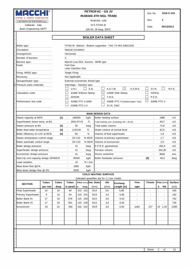
Boiler type: TITAN M - Bidrum - Bottom supported - TAG 7V-454 A/B/C/D/E
Circulation:
Arrangement:
Number of burners:
Burners type:
Fuels:
Firing: HRSG type:
Recovery:
Desuperheater type:
2 Pressure parts materials:
Natural circulation
Horizontal
3
Macchi Low NOx burners - MHM type
Fuel Gas
Lean Gas/Deo Gas
Single Firing
Not Applicable
External economizer finned type
Interstage - Injection type
U.N.I. E.N. A.S.T.M.
A.S.M.E.
D.I.N. N.F.E.
Calculation code:
Performance test code:
ASME Without Stamp ASME With Stamp ISPESL
AFNOR T.R.D. P.E.D.
ASME PTC 4-2000 ASME PTC 4.1(Abbreviated Test) ASME PTC 4
ASME PTC 4.4 D.I.N. 1942
MAIN DESIGN DATA
Steam capacity at MCR [1] : 180000 kg/h Boiler heating surface : 1886 m2
Superheated steam temp. at B/L : 355(+5°/-0°) °C
Total heating surf. (including SH + ECO) : 4517 m2
Steam pressure at B/L [2] : 30 barg Total water volume : 74,8 m3
Boiler feed water temperature [3] : 110/149 °C Water volume at normal level : 62,0 m3
Boiler efficiency on LHV at MCR [4] : 90 % Volume of final superheater : 1,8 m3
Steam temperature control range : 25÷110 % MCR Volume of primary superheater : 1,7 m3
Boiler automatic control range : 25÷110 % MCR Volume of economizer : 2,6 m3
Boiler design pressure
Superheater design pressure
Economizer design pressure
: 41 barg
: 41 barg
: 41 barg
E.P.R.S. geometrical
Furnace volume
Drums centerline
: 264,4 m2
: 342,00 m3
: 8000 mm
Start-Up vent capacity design 25%MCR : 45000 kg/h Boiler feedwater pressure [5] : 46,0 barg
Load variation
Blow down flow @1%
: 15 % / min
: 1800 kg/h
Blow down design flow @ 5% : 9000 kg/h
COILS HEATING SURFACE
Indicated quantities are for 1 ( one ) boiler
SECTION Tubes
Tubes Tubes Pitch [mm] Out. Diam. thk
Exchang. Fins Fins/m Fins [mm] Surface
per row deep in parall. tr. long. [mm] [mm] Length [m] type h thk [m2]
Final Superheater 10 10 60 103 101 50,8 3,6 5,85 - - - - 180
Primary Superheater 9
Boiler Bank #1 17
Boiler Bank #2 17
10 54
34 578
33 561
103 101
120 100
120 100
50,8
63,5
63,5
3,6
3,6
3,6
5,85
6,53
6,53
- - - -
- - - -
- - - -
162
752
730
Economizer 26 10 260 100 102 50,8 3,6 6,00 solid 157
Sheet
19 1,25
2 of
2289
13

Gallarate - Italy
Basic Engineering DEPT
PETROFAC - GS JV
RUWAIS 4TH NGL TRAIN
RUWAIS, UAE
N° 5 TITAN M
180 t/h, 30 barg, 355°C
Doc No. 1015-C-310
Rev. 2
Date 05/12/2011
BOILER DATA SHEET
BOILER TUBES - MEMBRANED WALLS
Indicated quantities are for 1 ( one ) boiler
FURNACE [6]
Depth 10443 mm Width 4513,5 mm Avg. height 7130 mm Outlet width 1593 mm
Volume 342 m3 E.P.R.S. 264,4 m2 Heat transf. Surf. 280,8 m2 Outlet height 7175 mm
Design pressure 889 mmH2O Test pressure 508 mmH2O
Description
Pitch
[mm]
Avg.
length
[mm] [7]
Outside
diam.
[mm]
Thick.
[mm]
Corrosion
allowance
[mm]
Number
of tubes
Material
Design
pressure
[barg]
Design
temp.
[°C] [8]
TUBES
"D" wall 88,5 16500 63,5 3,6 1,0 117 SA 210 Gr. A1 41,0 385
Side wall 88,5 7765 63,5 3,6 1,0 98 SA 210 Gr. A1 41,0 385
Front wall 88,5 8050 63,5 3,6 1,0 43 SA 210 Gr. A1 41,0 385
Rear wall 88,5 8050 63,5 3,6 1,0 51 SA 210 Gr. A1 41,0 385
HEADERS [11]
Front wall header 4625 219,1 18,26 3,2 2 SA 106 Gr. B 41,0 276
Rear wall header 4625 219,1 18,26 3,2 2 SA 106 Gr. B 41,0 276
RISERS AND FEEDERS [9]
Risers 4350 76,1 4 1,0 26 SA 210 Gr. A1 41 276
Feeders 4000 76,1 4 1,0 20 SA 210 Gr. A1 41 276
BOILER BANK SIDE WALLS
Depth 10443 mm Width 2160 mm Avg. height 6525 mm
Volume 147 m3 E.P.R.S. 140 m2 Heat transf. Surf. 147,1 m2
Description
Pitch
[mm]
Avg.
length
[mm]
Outside
diam.
[mm]
Thick.
[mm]
Corrosion
allowance
[mm]
Number
of tubes
Material
Design
pressure
[barg]
Design
temp.
[°C]
TUBES
Side wall 88,5 8050 63,5 3,6 1,0 111 SA 210 Gr. A1 41 385
Double side wall SH [10] 100 7667 76,1 4 1,0 26 SA 210 Gr. A1 41 385
Front Wall 120 7000 76,1 4 1,0 17 SA 210 Gr. A1 41 385
Screen 354/100 7500 63,5 3,6 1 6 SA 210 Gr. A1 41 385
Sheet 3 of 13

Gallarate - Italy
Basic Engineering DEPT
PETROFAC - GS JV
RUWAIS 4TH NGL TRAIN
RUWAIS, UAE
N° 5 TITAN M
180 t/h, 30 barg, 355°C
Doc No. 1015-C-310
Rev. 2
Date 05/12/2011
BOILER DATA SHEET
BOILER TUBES - SUPERHEATER
Indicated quantities are for 1 ( one ) boiler
FINAL SUPERHEATER
Arrangement In line Staggered Flow Parallel Counter Cross
Tubes per row 10 Number of rows 10 Tubes in parallel 60 Avg. exchanging height 5850 mm
Description
Pitch
tr. long
[mm]
Avg.
length
[mm] [7]
Outside
diam.
[mm]
Thick.
[mm]
Corrosion
allowance
[mm]
Number
of tubes
Material
Design
pressure
[barg]
Design
temp.
[°C] [8]
TUBES
SH tubes 103 96 9400 50,8 3,6 1,3 120 SA 213 Gr. T22 41 490
HEADERS / NOZZLES / JUMPERS [11]
Inlet header 1061,5 355,6 23,83 3,2 1 SA 335 Gr. P11 41 352
Outlet header 1061,5 355,6 23,83 3,2 1 SA 335 Gr. P11 41 385
1 Inlet Nozzle 400 355,6 27,79 3,2 1 SA 335 Gr. P11 41 352
1 Outlet Nozzle 300 355,6 27,79 3,2 1 SA 335 Gr. P11 41 385
INLET HEADER
Saturated Superheated steam steam from DSH
diaphragm
Superheated
steam to DSH Superheated steam outlet to BL
OUTLET HEADER refractory
INLET
HEADER
OUTLET
HEADER Tubes to be
protected
Sheet 4 of 13

PETROFAC - GS JV
RUWAIS 4TH NGL TRAIN
RUWAIS, UAE
Doc No.
Rev.
1015-C-310
2
Gallarate - Italy
Basic Engineering DEPT
N° 5 TITAN M
180 t/h, 30 barg, 355°C
Date 05/12/11
BOILER DATA SHEET
BOILER TUBES - SUPERHEATER
Indicated quantities are for 1 ( one ) boiler
PRIMARY SUPERHEATER Arrangement In line Staggered Flow Parallel Counter Cross
Tubes per row 9 Number of rows 10 Tubes in parallel 54 Avg. exchanging height 5850 mm
Pitch Avg. Outside Thick. Corrosion Number Design Design
Description tr. long length diam. allowance of tubes Material pressure temp.
[mm] [mm] [7] [mm] [mm] [mm] [barg] [°C] [8]
TUBES SH tubes 103 96 9400 50,8 3,6 1,3 108 SA 213 Gr. T22 41 465
HEADERS / NOZZLES / JUMPERS [11]
Inlet header 1010 355,6 23,83 3,2 1 SA 335 Gr. P11 41 352
Outlet header 1010 355,6 23,83 3,2 1 SA 335 Gr. P11 41 385
1 Inlet Nozzle 400 355,6 27,79 3,2 1 SA 335 Gr. P11 41 352
1 Outlet Nozzle 750 355,6 27,79 3,2 1 SA 335 Gr. P11 41 385
FURNACE
PRIMARY
SUPERHEATER
FINAL
SUPERHEATER
BOILER BANK #1
Sheet 5 of 13

Gallarate - Italy
Basic Engineering DEPT
PETROFAC - GS JV
RUWAIS 4TH NGL TRAIN
RUWAIS, UAE
N° 5 TITAN M
180 t/h, 30 barg, 355°C
Doc No. 1015-C-310
Rev. 2
Date 05/12/2011
BOILER DATA SHEET
BOILER TUBES - EVAPORATOR
Indicated quantities are for 1 ( one ) boiler
BOILER BANK #1
Arrangement In line Staggered
1 Tubes per row 17 Number of rows 34 Tubes in parallel 578 Avg. exchanging length 6525 mm
Description
Pitch
tr. long
[mm]
Avg.
length
[mm] [7]
Outside
diam.
[mm]
Thick.
[mm]
Corrosion
allowance
[mm]
Number
of tubes
Material
Design
pressure
[barg]
Design
temp.
[°C] [8]
TUBES
Tubes 120 100 7000 63,5 3,6 1,0 578 SA 210 Gr. A1 41 385
BOILER BANK #2
Arrangement In line Staggered
1 Tubes per row 17 Number of rows 33 Tubes in parallel 561 Avg. exchanging length 6525 mm
Description
Pitch
tr. long
[mm]
Avg.
length
[mm]
Outside
diam.
[mm]
Thick.
[mm]
Corrosion
allowance
[mm]
Number
of tubes
Material
Design
pressure
[barg]
Design
temp.
[°C] [8]
TUBES
Tubes 120 100 7000 63,5 3,6 1,0 561 SA 210 Gr. A1 41 385
Sheet 6 of 13

Gallarate - Italy
Basic Engineering DEPT
PETROFAC - GS JV
RUWAIS 4TH NGL TRAIN
RUWAIS, UAE
N° 5 TITAN M
180 t/h, 30 barg, 355°C
Doc No. 1015-C-310
Rev. 2
Date 05/12/2011
BOILER DATA SHEET
BOILER TUBES - ECONOMIZER
Indicated quantities are for 1 ( one ) boiler
ECONOMIZER
Arrangement In line Staggered Flow Parallel Counter Cross
Tubes per row 26 Number of rows 10 Tubes in parallel 26 Avg. exchanging length 5997 mm
Description
Pitch
tr. long
[mm]
Avg.
length
[mm] [7]
Outside
diam.
[mm]
Thick.
[mm]
Corrosion
allowance
[mm]
Number
of tubes
Material
Design
pressure
[barg]
Design
temp.
[°C] [8]
TUBES
Tubes 100 102 6150 50,8 3,6 1,0 260 SA 210 Gr. A1 41 385
HEADERS / NOZZLES / JUMPERS [11]
Inlet header 2950 219,1 15,09 3,2 1 SA 106 Gr. B 41 276
Outlet header 2950 219,1 15,09 3,2 1 SA 106 Gr. B 41 276
FINS
Description
Type
Finned
length
[mm]
Fins x
meter
[fins/m]
Height
[mm]
Thick.
[mm]
Segment
[mm]
Material
[23]
Max Fin
Temperature
[°C]
Tubes solid 5997 157 19 1,25 - EN 10130 DC04 454
Sheet 7 of 13
Gallarate - Italy
Basic Engineering DEPT
PETROFAC - GS JV
RUWAIS 4TH NGL TRAIN
RUWAIS, UAE
N° 5 TITAN M
180 t/h, 30 barg, 355°C
Doc No. 1015-C-310
Rev. 2
Date 05/12/2011
BOILER DATA SHEET
PRESSURE PARTS
Indicated quantities are for 1 ( one ) boiler
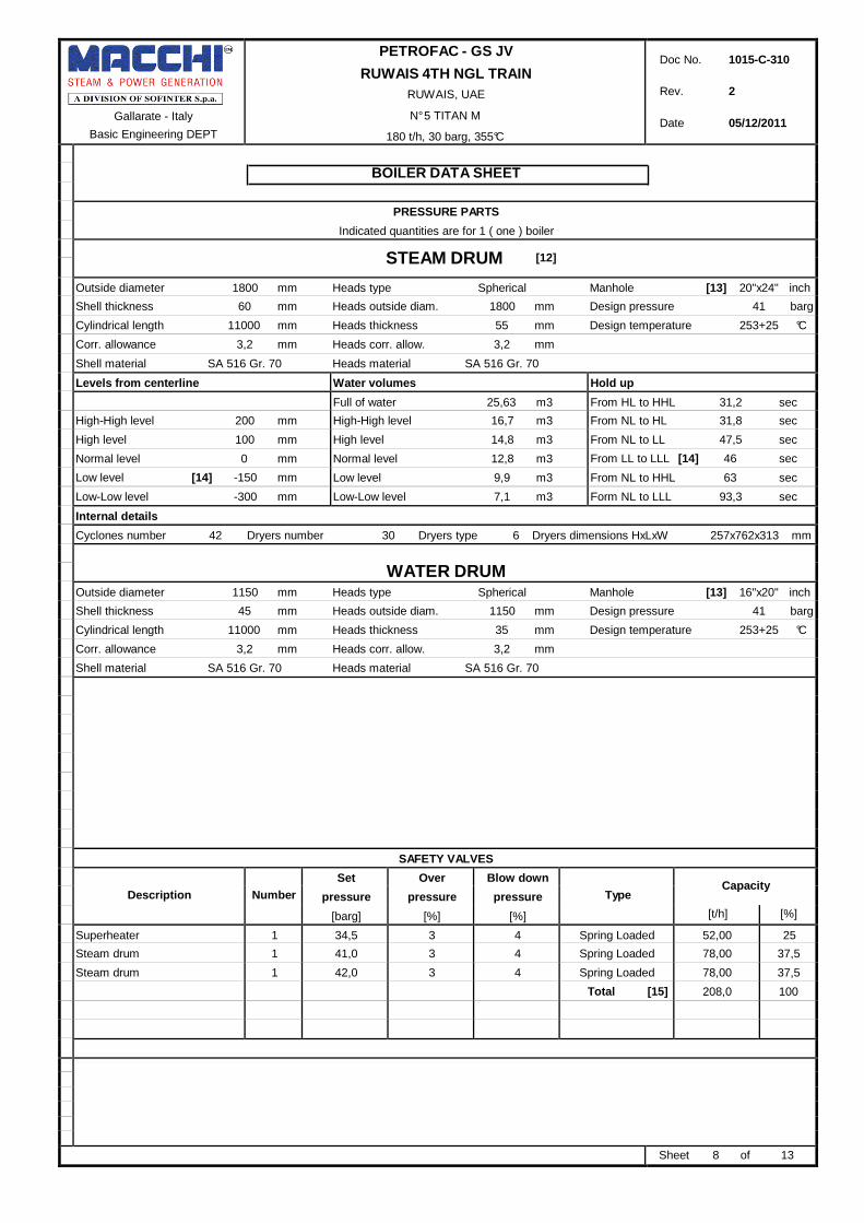
STEAM DRUM [12]
Outside diameter 1800 mm Heads type Spherical Manhole [13] 20"x24" inch
Shell thickness 60 mm Heads outside diam. 1800 mm Design pressure 41 barg
Cylindrical length 11000 mm Heads thickness 55 mm Design temperature 253+25 °C
Corr. allowance 3,2 mm Heads corr. allow. 3,2 mm
Shell material SA 516 Gr. 70 Heads material SA 516 Gr. 70
Levels from centerline Water volumes Hold up
Full of water 25,63 m3 From HL to HHL 31,2 sec
High-High level 200 mm High-High level 16,7 m3 From NL to HL 31,8 sec
High level 100 mm High level 14,8 m3 From NL to LL 47,5 sec
Normal level 0 mm Normal level 12,8 m3 From LL to LLL [14] 46 sec
Low level [14] -150 mm Low level 9,9 m3 From NL to HHL 63 sec
Low-Low level -300 mm Low-Low level 7,1 m3 Form NL to LLL 93,3 sec
Internal details
Cyclones number 42 Dryers number 30 Dryers type 6 Dryers dimensions HxLxW 257x762x313 mm
WATER DRUM
Outside diameter 1150 mm Heads type Spherical Manhole [13] 16"x20" inch
Shell thickness 45 mm Heads outside diam. 1150 mm Design pressure 41 barg
Cylindrical length 11000 mm Heads thickness 35 mm Design temperature 253+25 °C
Corr. allowance 3,2 mm Heads corr. allow. 3,2 mm
Shell material SA 516 Gr. 70 Heads material SA 516 Gr. 70
SAFETY VALVES
Description
Number
Set
pressure
[barg]
Over
pressure
[%]
Blow down
pressure
[%]
Type
Capacity
[t/h] [%]
Superheater 1 34,5 3 4 Spring Loaded 52,00 25
Steam drum 1 41,0 3 4 Spring Loaded 78,00 37,5
Steam drum 1 42,0 3 4 Spring Loaded 78,00 37,5
Total [15] 208,0 100
Sheet 8 of 13

Gallarate - Italy
Basic Engineering DEPT
PETROFAC - GS JV
RUWAIS 4TH NGL TRAIN
RUWAIS, UAE
N° 5 TITAN M
180 t/h, 30 barg, 355°C
Doc No. 1015-C-310
Rev. 2
Date 05/12/2011
BOILER DATA SHEET
BURNERS
Indicated quantities are for 1 ( one ) boiler
FUELS: Fuel Gas/Lean Gas/Deo Gas
Burners duty at 100 %MCR 147,1 MW (126450000 Kcal/h)
Burners duty at 110 %MCR 162,7 MW (139866000 Kcal/h)
Burners duty at 81 %MCR 117,9 MW (101389596 Kcal/h)
Burners duty at 25 %MCR 36,6 MW (31435150 Kcal/h)
Burners turn-down 1 : 5 with all fuel gas
Single Burner Design 56 MW ( 48150000 Kcal/h)
MECHANICAL DATA
dp
average height
h2
depth
h1
ds-bottom
width
Furnace average height 7130 mm
Furnace depth 10443,0 mm
Furnace width 4513,5 mm
Number of burners 3
ds-bottom 1405,0 mm
h1 2050 mm
h2 2050 mm
dp 2179,75 mm
Furnace peephole 6"
Sheet 9 of 13
Gallarate - Italy
Basic Engineering DEPT
PETROFAC - GS JV
RUWAIS 4TH NGL TRAIN
RUWAIS, UAE
N° 5 TITAN M
180 t/h, 30 barg, 355°C
Doc No. 1015-C-310
Rev. 2
Date 05/12/2011
BOILER DATA SHEET
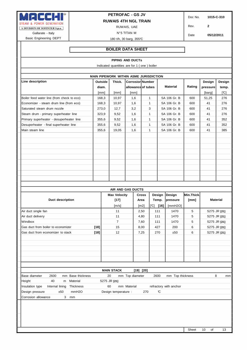
PIPING AND DUCTs
Indicated quantities are for 1 ( one ) boiler MAIN PIPEWORK WITHIN ASME JURISDICTION
Line description Outside
diam.
[mm]
Thick.
[mm]
Corrosion
allowance
[mm]
Number
of tubes
Material
Rating
Design
pressure
[barg]
Design
temp.
[°C]
Boiler feed water line (from check to eco) 168,3 10,97 1,6 1 SA 106 Gr. B 600 51,25 276
Economizer - steam drum line (from eco) 168,3 10,97 1,6 1 SA 106 Gr. B 600 41 276
Saturated steam drum nozzle 273,0 12,7 3,2 3 SA 106 Gr. B 600 41 276
Steam drum - primary superheater line 323,9 9,52 1,6 1 SA 106 Gr. B 600 41 276
Primary superheater - desuperheater line 355,6 9,52 1,6 1 SA 106 Gr. B 600 41 352
Desuperheater - final superheater line 355,6 9,52 1,6 1 SA 106 Gr. B 600 41 352
Main steam line 355,6 19,05 1,6 1 SA 106 Gr. B 600 41 385
AIR AND GAS DUCTS
Duct description
Max Velocity
[17]
[m/s]
Cross
Area
[m2]
Design
Temp.
[°C] [16]
Design
pressure
[mmH2O]
Min.Thick.
[mm]
Material
Air duct single fan 11 2,50 111 1470 5 S275 JR [21]
Air duct delivery 11 4,80 111 1470 5 S275 JR [21]
Windbox 7 7,60 111 1470 5 S275 JR [21]
Gas duct from boiler to economizer [18] 15 8,00 427 200 6 S275 JR [21]
Gas duct from economizer to stack [18] 12 7,25 270 ±50 6 S275 JR [21]
MAIN STACK [19] [20]
Base diameter 2600 mm Base thickness 20 mm Top diameter 2600 mm Top thickness 8 mm
Height 40 m Material S275 JR [21]
Insulation type Internal lining Thickness 60 mm Material refractory with anchor
Design pressure ±50 mmH2O Design temperature : 270 °C
Corrosion allowance 3 mm
Sheet 10 of 13

Gallarate - Italy
Basic Engineering DEPT
PETROFAC - GS JV
RUWAIS 4TH NGL TRAIN
RUWAIS, UAE
N° 5 TITAN M
180 t/h, 30 barg, 355°C
Doc No. 1015-C-310
Rev. 2
Date 05/12/2011
BOILER DATA SHEET
INTERNAL INSULATION
Indicated quantities are for 1 ( one ) boiler
INTERNAL TYPE INSULATION
GAS DUCT FROM BOILER TO ECONOMIZER
INTERNAL LINING Layer 2 Casing Material refractory Material HES cement [22] Material S275 JR [21] Thickness 50 mm Thickness 1 mm Thickness 6 mm type Insulating castable Design pressure 200 mmH2O density ≥1340 kg/m
3 Design temperature 427 °C
GAS DUCT FROM ECONOMIZER TO STACK
INTERNAL LINING Layer 2 Casing
Material refractory Material HES cement [22] Material S275 JR [21] Thickness 50 mm Thickness 1 mm Thickness 6 mm type Insulating castable Design pressure ±50 mmH2O density ≥1340 kg/m
3 Design temperature 270 °C
Sheet 11 of 13
Gallarate - Italy
Basic Engineering DEPT
PETROFAC - GS JV
RUWAIS 4TH NGL TRAIN
RUWAIS, UAE
N° 5 TITAN M
180 t/h, 30 barg, 355°C
Doc No. 1015-C-310
Rev. 2
Date 05/12/2011
BOILER DATA SHEET
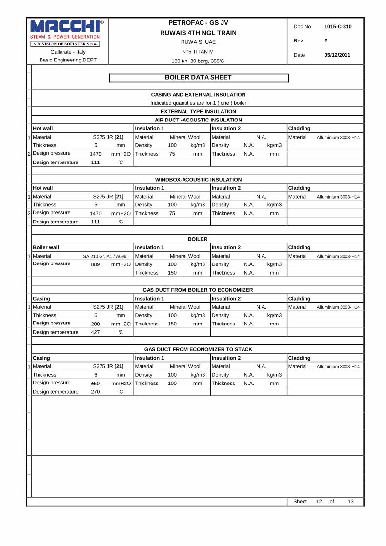
CASING AND EXTERNAL INSULATION
Indicated quantities are for 1 ( one ) boiler
EXTERNAL TYPE INSULATION
AIR DUCT -ACOUSTIC INSULATION
Hot wall Insulation 1 Insulation 2 Cladding
1 Material S275 JR [21] Material Mineral Wool Material N.A. Material Alluminium 3003-H14
Thickness 5 mm Density 100 kg/m3 Density N.A. kg/m3 2 Design pressure 1470 mmH2O Thickness 75 mm Thickness N.A. mm Design temperature 111 °C
WINDBOX-ACOUSTIC INSULATION
Hot wall Insulation 1 Insualtion 2 Cladding
1 Material S275 JR [21] Material Mineral Wool Material N.A. Material Alluminium 3003-H14
Thickness 5 mm Density 100 kg/m3 Density N.A. kg/m3 2 Design pressure 1470 mmH2O Thickness 75 mm Thickness N.A. mm Design temperature 111 °C
BOILER
Boiler wall Insulation 1 Insulation 2 Cladding
1 Material SA 210 Gr. A1 / A696 Material Mineral Wool Material N.A. Material Alluminium 3003-H14
Design pressure 889 mmH2O Density 100 kg/m3 Density N.A. kg/m3 Thickness 150 mm Thickness N.A. mm
GAS DUCT FROM BOILER TO ECONOMIZER
Casing Insulation 1 Insualtion 2 Cladding
1 Material S275 JR [21] Material Mineral Wool Material N.A. Material Alluminium 3003-H14
Thickness 6 mm Density 100 kg/m3 Density N.A. kg/m3 Design pressure 200 mmH2O Thickness 150 mm Thickness N.A. mm Design temperature 427 °C
GAS DUCT FROM ECONOMIZER TO STACK
Casing Insulation 1 Insualtion 2 Cladding
1 Material S275 JR [21] Material Mineral Wool Material N.A. Material Alluminium 3003-H14
Thickness 6 mm Density 100 kg/m3 Density N.A. kg/m3 Design pressure ±50 mmH2O Thickness 100 mm Thickness N.A. mm Design temperature 270 °C
Sheet 12 of 13
Gallarate - Italy
Basic Engineering DEPT
PETROFAC - GS JV
RUWAIS 4TH NGL TRAIN
RUWAIS, UAE
N° 5 TITAN M
180 t/h, 30 barg, 355°C
Doc No. 1015-C-310
Rev. 2
Date 05/12/2011
BOILER DATA SHEET
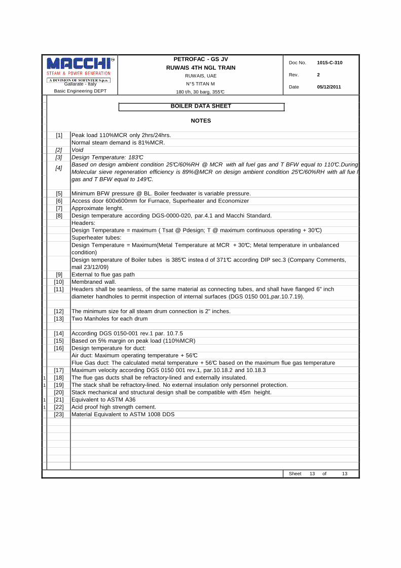
NOTES
[1] Peak load 110%MCR only 2hrs/24hrs.
Normal steam demand is 81%MCR.
[2] Void
[3] Design Temperature: 183°C
[4] Based on design ambient condition 25°C/60%RH @ MCR with all fuel gas and T BFW equal to 110°C.During
Molecular sieve regeneration efficiency is 89%@MCR on design ambient condition 25°C/60%RH with all fue l
gas and T BFW equal to 149°C.
[5] Minimum BFW pressure @ BL. Boiler feedwater is variable pressure.
[6] Access door 600x600mm for Furnace, Superheater and Economizer
[7] Approximate lenght.
[8] Design temperature according DGS-0000-020, par.4.1 and Macchi Standard.
Headers:
Design Temperature = maximum ( Tsat @ Pdesign; T @ maximum continuous operating + 30°C)
Superheater tubes:
Design Temperature = Maximum(Metal Temperature at MCR + 30°C; Metal temperature in unbalanced
condition)
Design temperature of Boiler tubes is 385°C instea d of 371°C according DIP sec.3 (Company Comments,
mail 23/12/09)
[9] External to flue gas path
[10] Membraned wall.
[11] Headers shall be seamless, of the same material as connecting tubes, and shall have flanged 6" inch
diameter handholes to permit inspection of internal surfaces (DGS 0150 001,par.10.7.19). [12] The minimum size for all steam drum connection is 2" inches.
[13] Two Manholes for each drum
[14] According DGS 0150-001 rev.1 par. 10.7.5
[15] Based on 5% margin on peak load (110%MCR)
[16] Design temperature for duct:
Air duct: Maximum operating temperature + 56°C
Flue Gas duct: The calculated metal temperature + 56°C based on the maximum flue gas temperature
[17] Maximum velocity according DGS 0150 001 rev.1, par.10.18.2 and 10.18.3
1 [18] The flue gas ducts shall be refractory-lined and externally insulated.
1 [19] The stack shall be refractory-lined. No external insulation only personnel protection.
[20] Stack mechanical and structural design shall be compatible with 45m height.
1 [21] Equivalent to ASTM A36
1 [22] Acid proof high strength cement.
[23] Material Equivalent to ASTM 1008 DDS
Sheet 13 of 13