movitrac® lt option cards / operating instructions / 2009-09option cards edition 09/2009 16822013 /...
TRANSCRIPT

Drive Electronics \ Drive Automation \ System Integration \ Services
Operating Instructions
MOVITRAC® LTOption Cards
Edition 09/2009 16822013 / EN

SEW-EURODRIVE—Driving the world

Operating Instructions – MOVITRAC® LT Option Cards 3
1 Important Notes................................................................................................. 51.1 How to use the operating instructions ....................................................... 51.2 Structure of the safety notes ..................................................................... 51.3 Right to claim under limited warranty ........................................................ 61.4 Exclusion of liability ................................................................................... 61.5 Copyright notice ........................................................................................ 61.6 Waste disposal.......................................................................................... 7
2 Safety Notes ...................................................................................................... 82.1 Preliminary information ............................................................................. 82.2 General ..................................................................................................... 82.3 Target group ............................................................................................. 92.4 Designated use ......................................................................................... 92.5 Transport................................................................................................. 102.6 Installation / assembly............................................................................. 102.7 Electrical connection ............................................................................... 112.8 Safe disconnection.................................................................................. 112.9 Startup / operation .................................................................................. 112.10 Operation and servicing .......................................................................... 12
3 Mechanical Installation................................................................................... 133.1 Preliminary work...................................................................................... 133.2 Installation procedure.............................................................................. 13
4 Second Analog Input ...................................................................................... 154.1 Supported unit types ............................................................................... 154.2 Overview ................................................................................................. 154.3 Technical data......................................................................................... 154.4 Electrical interface................................................................................... 164.5 Operation ................................................................................................ 17
5 Second relay output........................................................................................ 185.1 Supported unit types ............................................................................... 185.2 Overview ................................................................................................. 185.3 Electrical interface................................................................................... 195.4 Technical data......................................................................................... 195.5 Operation ................................................................................................ 20
6 Third relay output............................................................................................ 226.1 Supported unit types ............................................................................... 226.2 Overview ................................................................................................. 226.3 Electrical interface................................................................................... 236.4 Technical data......................................................................................... 236.5 Operation ................................................................................................ 24
7 Two indicator relay.......................................................................................... 257.1 Supported unit types ............................................................................... 257.2 Overview ................................................................................................. 257.3 Electrical interface................................................................................... 267.4 Technical data......................................................................................... 277.5 Operation in MOVITRAC® LTE-B ........................................................... 277.6 Operation in MOVITRAC® LTP............................................................... 28

4 Operating Instructions – MOVITRAC® LT Option Cards
8 PI Controller..................................................................................................... 298.1 Supported unit types ............................................................................... 298.2 Overview ................................................................................................. 298.3 Electrical interface................................................................................... 308.4 Technical data......................................................................................... 308.5 Operation ................................................................................................ 31
9 Converter card................................................................................................. 339.1 Supported unit types ............................................................................... 339.2 Overview ................................................................................................. 339.3 Electrical interface................................................................................... 349.4 Technical data......................................................................................... 349.5 Operation ................................................................................................ 35
10 Local switchboard........................................................................................... 3610.1 Supported unit types ............................................................................... 3610.2 Overview ................................................................................................. 3610.3 Electrical interface................................................................................... 3710.4 Technical data......................................................................................... 37
11 Index................................................................................................................. 38

Operating Instructions – MOVITRAC® LT Option Cards 5
1 How to use the operating instructionsImportant Notes
Operating Instructions1 Important Notes1.1 How to use the operating instructions
The operating instructions are an integral part of the product and contain importantinformation on operation and service. The operating instructions are written for allemployees who assemble, install, startup, and service this product.The operating instructions must be accessible and legible. Make sure that personsresponsible for the system and its operation, as well as persons who work independentlyon the unit, have read through the operating instructions carefully and understood them.Consult SEW-EURODRIVE if you have any questions or if you require further informa-tion.
1.2 Structure of the safety notesThe safety notes in these operating instructions are structured as follows:
Symbol SIGNAL WORD
Nature and source of danger.Possible consequence(s) if the safety notes are disregarded.• Measure(s) to prevent the danger.
Symbol Signal Word Meaning Consequences if disregarded
Example:
General hazard
Specific hazard,e.g. electric shock
DANGER Imminent danger Severe or fatal injuries
WARNING Possible dangerous situation Severe or fatal injuries
CAUTION Possible dangerous situation Minor injuries
NOTICE Possible damage to property Damage to the drive system or its environ-ment
TIP Useful information or tip.Simplifies the handling of the drive system.

6 Operating Instructions – MOVITRAC® LT Option Cards
1 Right to claim under limited warranty Important Notes
Unless the information in the operating instructions is adhered to, it will be impossible toensure:• Trouble-free operation• Fulfilment of any rights to claim under guarantee
Consequently, read the operating instructions before you start working with theproduct!
1.3 Right to claim under limited warrantyAdhering to the operating instructions is a prerequisite for fault-free operation and thefulfillment of any right to claim under warranty. Read the operating instructions beforeyou start working with the unit.Make sure that the operating instructions are available to persons responsible for thesystem and its operation as well as to persons who work independently on the unit. Youmust also ensure that the documentation is legible.
1.4 Exclusion of liabilityYou must comply with the information contained in these operating instructions toensure safe operation of the MOVITRAC® LT and to achieve the specified product char-acteristics and performance requirements. SEW-EURODRIVE does not assume liabilityfor injury to persons or damage to equipment or property resulting from non-observanceof these operating instructions. In such cases, any liability for defects is excluded.
1.5 Copyright notice© 2008 – SEW-EURODRIVE. All rights reserved.Any reproduction, modification, distribution or unintended use, in whole or in part, isprohibited.

Operating Instructions – MOVITRAC® LT Option Cards 7
1 Waste disposalImportant Notes
1.6 Waste disposalPlease dispose of the following parts in accordance with the current regulations:• Electronics scrap (printed-circuit boards)• Plastic (housing)• Sheet metal• Copper

8 Operating Instructions – MOVITRAC® LT Option Cards
2 Preliminary information Safety Notes
2 Safety NotesThe following basic safety notes must be read carefully to prevent injury to persons anddamage to property. The operator must ensure that the basic safety notes are read andobserved. Make sure that persons responsible for the plant and its operation, as well aspersons who work independently on the unit, have read through the operating instruc-tions carefully and understood them. If you are unclear about any of the information in this documentation, or if you requirefurther information, please contact SEW-EURODRIVE.
2.1 Preliminary informationThe following safety notes predominantly refer to the use of frequency inverters and theiraccessories. Additionally, when using drives with motors or gearmotors, observe thecorresponding safety notes in the respective operating instructions.Please also observe the supplementary safety notes in the individual sections of thisdocument.
2.2 General
Removing covers without authorization, improper use as well as incorrect installation oroperation may result in severe injuries to persons or damage to property.
DANGER
During operation, frequency inverters and their accessories can have live, bare partsaccording to their degree of protection.Severe or fatal injuries.• All work related to transportation, storage, setup / mounting, connection, startup,
maintenance and repair may only be carried out by qualified personnel, in strictobservation of:– The relevant detailed operating instructions– The warning and safety signs on the motor / gearmotor and electronic compo-
nents– All other project planning documents, operating instructions and wiring
diagrams related to the drive– The specific regulations and requirements for the system– The national / regional regulations governing safety and the prevention of
accidents• Never install damaged products.• Immediately report any damages to the shipping company.

Operating Instructions – MOVITRAC® LT Option Cards 9
2 Target groupSafety Notes
2.3 Target groupAny mechanical work may only be performed by adequately qualified personnel.Qualified personnel in this context are persons who are familiar with the setup,mechanical installation, trouble shooting and maintenance for this product. Further, theyare qualified as follows:• Training in mechanical engineering, e.g. as a mechanic or mechatronics technician
(final examinations must have been passed).• They are familiar with these operating instructions.Any electronic work may only be performed by adequately qualified electricians.Qualified electricians in this context are persons who are familiar with the electronicinstallation, startup, trouble shooting and maintenance for this product. Further, they arequalified as follows:• Training in electrical engineering, e.g. as an electrician or mechatronics technician
(final examinations must have been passed).• They are familiar with these operating instructions.All work in further areas of transportation, storage, operation and waste disposal may becarried out only by persons who are trained appropriately.
2.4 Designated useFrequency inverters and their accessories are components for controlling asynchronousAC motors. Frequency inverters are components intended for installation in electricalsystems or machines. Never connect capacitive loads. Operation with capacitive loadsresults in over voltages and may destroy the unit.The following standards apply, if the frequency inverters are marketed in the EU / EFTA:• In case of installation in machines, startup of the drive inverters (meaning the start of
proper use) is prohibited until it is determined that the machine meets the require-ments stipulated in the EC Directive 98/37/EC (machine directive); observeEN 60204.
• Startup (i.e. the start of designated use) is only permitted under observance of theEMC (2004/108/EC) directive.
• The frequency inverters comply with the requirements of the Low Voltage Directive2006/95/EC. The harmonized standards of the EN 61800-5-1/DIN VDE T105 seriesin connection with EN 60439-1/VDE 0660 part 500 and EN 60146/VDE 0558 areapplied to these frequency inverters.
Observe the technical data and the connection requirements specified on the nameplateand the operating instructions.
2.4.1 Safety functionsFrequency inverters from SEW-EURODRIVE must not perform any safety functionsunless the inverters are subordinate to other safety systems. Use higher-level safety systems to ensure protection of equipment and personnel.

10 Operating Instructions – MOVITRAC® LT Option Cards
2 Transport Safety Notes
2.5 TransportImmediately upon receipt, inspect the shipment for any damage that may have occurredduring transportation. Never install or start up damaged products. In the event of damage please submit acomplaint to the transport company immediately.
2.6 Installation / assemblyThe units must be installed and cooled according to the regulations and specificationsin this documentation.Protect the frequency inverters from excessive strain. Do not twist any components anddo not modify the insulation spaces. Do not touch any electronic components orcontacts.Frequency inverters contain components that can easily be damaged by electrostaticenergy and improper handling. Electric components must not be mechanically damagedor destroyed.The unit meets all requirements for reliable isolation of power and electronicsconnections in accordance with UL508. All connected circuits must also satisfy therequirements for reliable isolation so as to guarantee reliable isolation.Take suitable measures to ensure that the connected motor does not start upautomatically when the inverter is switched on. To do this, connect binary inputs DI01through DI03 to GND / 0V. The following applications are prohibited unless the unit is explicitly designed for suchuse:• Use in potentially explosive atmospheres.• Use in environments with harmful substances:
– Oils– Acids– Gases– Vapors– Dust– Radiated interference– Other harmful environments
• Use subject to mechanical vibration and shock loads in excess of the requirementsin EN 50178.
• Use in non-stationary applications which are subject to mechanical vibration andimpact loads in excess of the requirements in EN 61800-5-1.
• If the inverter or its accessories perform safety functions which have to guarantee theprotection of machinery and people.

Operating Instructions – MOVITRAC® LT Option Cards 11
2 Electrical connectionSafety Notes
2.7 Electrical connectionObserve the applicable national accident prevention guidelines when working on livefrequency inverters (e.g. BGV A3 for Germany).During installation, observe the specifications regarding cable cross sections, fusing andprotective conductor connection.Protective measures and protection devices must comply with the regulations in force(e.g. EN 60204 or EN 61800-5-1).– Grounding the unit is a necessary protective measure.– Overcurrent protection devices are a necessary protective measure.
2.8 Safe disconnectionThe MOVITRAC® LT units and their accessories meet all requirements for safedisconnection of power and electronic connections in accordance with EN 61800-5-1.All connected circuits must also satisfy the requirements for safe disconnection.
2.9 Startup / operationSystems with integrated frequency inverters must be equipped with additional monitor-ing and protection devices, as applicable, according to the relevant safety guidelinesand regulations, such as legislation governing technical equipment, accident preventionregulations, etc. Do not touch live components or power connections until 10 minutes after disconnectingthe frequency inverters from the supply voltage because there may still be somecharged capacitors. Observe the corresponding labels on the frequency inverter.Keep all covers and doors closed during operation.The fact that the status LED and other display elements are no longer illuminated doesnot indicate that the unit has been disconnected from the mains and no longer carriesany voltage.Mechanical blocking or safety functions inside the unit may result in the motor comingto a standstill. Eliminating the cause of the problem or performing a reset may result inthe drive restarting automatically. If, for safety reasons, this is not permitted for thedriven machine, disconnect the unit from the supply system before correcting the error.

12 Operating Instructions – MOVITRAC® LT Option Cards
2 Operation and servicing Safety Notes
2.10 Operation and servicing
WARNING
Dangerous voltages are present in the output terminals and the cables and motorterminals connected to them when the unit is switched on. The unit is not necessarily deenergized when the LEDs and the 7-segment displayare off. Dangerous voltages may also be present when the unit is inhibited and themotor at a standstill.High voltages are also present in the terminals and within the drive for up to 10 min-utes after the electrical supply has been disconnected.Severe or fatal injuries from electric shock.• Disconnect and isolate the MOVITRAC® LT from the electrical supply at least
10 minutes before commencing any work on it.
WARNING
Safety functions inside the unit or a mechanical blockage may cause the motor tostop. The removal of the source of the malfunction or a reset can result in anautomatic restart of the drive. Severe or fatal injuries.• Disconnect the unit from the supply system before correcting the fault.

Operating Instructions – MOVITRAC® LT Option Cards 13
3 Preliminary workMechanical Installation
3 Mechanical Installation3.1 Preliminary work
• Turn the drive off and wait at least 10 minutes before installing the option card.
3.2 Installation procedure• Insert the option card into the MOVITRAC® LT control terminal strip.• Tighten all 11 terminal screws on the MOVITRAC® LT to ensure good electrical
contact.
WARNING
Dangerous voltages are present in the output terminals and the cables and motorterminals connected to them when the unit is switched on. The unit is not necessarily deenergized when the LEDs and the 7-segment displayare off. Dangerous voltages may also be present when the unit is inhibited and themotor at a standstill.High voltages are also present in the terminals and within the drive for up to 10 min-utes after the electrical supply has been disconnected.Severe or fatal injuries from electric shock.• Disconnect and isolate the MOVITRAC® LT from the electrical supply at least
10 minutes before commencing any work on it.
TIPWhen installing an option card into the following units, support the option card whilsttightening the terminal screws.• MOVITRAC® LTP, Size 1• MOVITRAC® LTP IP55 (all sizes)• MOVITRAC® LTE-B (all sizes)
TIPOnce the option cards have been installed and fully wired into an IP55 / NEMA 12 drive,the board must be bent slightly in a downwards direction to enable the front cover to beclosed. This does not affect the function of the option board.

14 Operating Instructions – MOVITRAC® LT Option Cards
3 Installation procedure Mechanical Installation
IP20 IP55
65875AXX 65874AXX

Operating Instructions – MOVITRAC® LT Option Cards 15
4 Supported unit typesSecond Analog Input
4 Second Analog Input
4.1 Supported unit types
4.2 OverviewThe second analog input can be used in applications where the speed reference for thedrive is required to be switched between 2 analog references. The typical application is where a drive is controlled remotely using a current referencebut needs to have a local option of control, usually with a potentiometer.
4.3 Technical data
Type Part number
OB LT 2ANIN 1820 1547
64759AXX
TIPThis option is only available for MOVITRAC® LTE-A.
Analog input 1 DC ±10 V, 4 – 20 mA
Analog input 1 DC ±10 V, 4 – 20 mA
Maximum input voltage DC ±50 V
Ambient temperature –10 – +50 °C
Conformity IP00, UL94V-0
Dimensions [mm] 56 × 24 (not pins) × 14
[in] 2.20 × 0.98 (not pins) × 0.56

16 Operating Instructions – MOVITRAC® LT Option Cards
4 Electrical interface Second Analog Input
4.4 Electrical interface
64746AXX
Pin no.
Signal Connection Description
1 0 V 0 V common for AI Ref. to activate DI1 – DI3 (100 mA max.)
2 DI1 Digital Input 1 Positive logic’Logic 1" input voltage range: DC 8 – 30 V"Logic 0" input voltage range: DC 0 – 2 VCompatible with PLC-requirement when 0 V is con-nected
3 DI 2 Digital Input 2
4 DI3 Digital Input 3
5 +10 V +10 V 10 V ref for AI / DI
6 AI 1 Analog Input 1 0 – 10 V, 0 – 20 mA
7 AI 2 Analog Input 2
8 AO / DO Analog Output (10-bit) / Digital output
0 – 10 V, 20 mA analog24 V / 20 mA digital
9 0 V 0 V common 0 V ref for analog output
10 Relay contact Relay contact N.O. relay contact (AC 250 V / DC 30 V @ 1 A)
11 Relay common Relay common
1 2 3 4 5 6 7 8 9 10 11
TIPThe signal connected to Digital Input 3 is used to switch between Analog Input 1(terminal 6) and Analog Input 2 (terminal 7).

Operating Instructions – MOVITRAC® LT Option Cards 17
4 OperationSecond Analog Input
4.5 Operation4.5.1 Switching between a voltage and a current speed reference
• Connect the voltage signal to terminal 6 and the current signal to terminal 7 of theoption module. – Each of these signals is referenced to terminal 9 (0 V). – The digital signal used to switch between the voltage and current inputs should
be connected to terminal 4 (digital input 3).• Set the parameters as follows:
– P-19 = 0– P-16 = 4 – 20 mA (or 0 – 20 mA / 20 – 4 mA, depending on required format)
4.5.2 Hand – Off – Auto-operation
• Connect the required analog reference signals to terminals 6 and 7 as describedabove. This mode of operation requires a 2-pole change-over, centre-off switch. – The first pole of the switch is used to enable the drive, where both "Hand" and
"Auto" positions should be connected to digital input 1. – The second pole of the switch is connected to digital input 3, as described above.
• Connect the common connection point of each of the switches to terminal 1 (0 V).• In a typical configuration, "Hand" will enable the drive using the voltage (local) refer-
ence, "Auto" will enable the drive using the current (remote) reference.
TIPWhen digital input 3 is open, the voltage format signal (connected to terminal 6) will beselected.

18 Operating Instructions – MOVITRAC® LT Option Cards
5 Supported unit types Second relay output
5 Second relay output
5.1 Supported unit typesThis option is available in 2 versions:• OB LT 2ROUT for MOVITRAC® LTE-A• OB LT 2ROUTB for MOVITRAC® LTE-B and MOVITRAC® LTP
5.2 OverviewThe 2nd relay output module can be used in applications where the analog output fromthe drive is converted to a relay output.Typical applications are where 2 relay outputs are required. The functions of the relaysare programmable in the drive and can be any of the following:• Drive enabled• Drive healthy• Drive at set speed• Drive at zero speed• Drive at maximum speed• Motor in overload
Type Part number
OB LT 2ROUT 1822 3168
OB LT 2ROUTB 1820 1555
64759AXX

Operating Instructions – MOVITRAC® LT Option Cards 19
5 Electrical interfaceSecond relay output
5.3 Electrical interface
5.4 Technical data
64746AXX
Terminal no.
Signal Connection Description
1 +24 V +24 V ref out Ref. to activate DI1 – DI3 (100 mA max.)
2 DI 1 Digital input 1 Positive logic"Logic 1" input voltage range: DC 8 – 30 V"Logic 0" input voltage range: DC 0 – 2 VCompatible with PLC requirement when 0 V is connected.
3 DI 2 Digital input 2
4 DI 3 Digital input 3 / thermistor contact
5 +10 V +10 V ref out 10 V ref for analog input (pot supply +, 10 mA max., 1 K Ω min.)
6 AI / DI Analog input (12 bit)Digital input 4
0 – 10 V, 0 – 20 mA, 4 – 20 mA"Logic 1" input voltage range: DC 8 – 30 V
7 0 V 0 V common 0 V ref for analog input (pot supply –)
8 Relay 2 contact Relay contact N.O. relay contact (AC 250 V / DC 30 V @ 1 A)
9 Relay 2 common Relay common
10 Relay 1 contact Relay contact N.O. relay contact (AC 250 V / DC 30 V @ 1 A)
11 Relay 1 common Relay common
1 2 3 4 5 6 7 8 9 10 11
TIPThe second relay output contacts are available on terminals 8 & 9. This relay utilisesthe drive’s analog / digital output for operation. Therefore the analog input is not avail-able when this module is fitted.
Max. relay switching voltage AC 250 V / DC 220 V
Max. relay switching current 1 A
Max. input voltage DC ±50 V
Conformity IP00, UL94V-0
Environmental –10 – +50 °C
Dimensions [mm] 56 × 24 (not pins) × 14
[in] 2.20 × 0.98 (not pins) × 0.56

20 Operating Instructions – MOVITRAC® LT Option Cards
5 Operation Second relay output
5.5 Operation5.5.1 Operation MOVITRAC® LTE-A (OB LT 2ROUT)Programming the first relay output
Since the first relay output is programmed using parameter P-18 in MOVITRAC® LTE-A,2 completely independent relay outputs are available. The following options aresupported for relay 1:
Programming the second relay output
The second relay output is controlled using MOVITRAC®LTE-A parameter P-25. Thisshould be set to either 2 or 3 as described below:
5.5.2 Operation MOVITRAC® LTE-B (OB LT 2ROUTB)Programming the first relay output
Since the first relay output is programmed using paramter P-18 in MOVITRAC® LTE-B,2 completely independent relay outputs are available. The following options aresupported for relay 1:
P-18 Relay 1 output function select
0: Drive enabled Defines the function of User Relay 1 when the operating conditions are met.• Disabled: Contacts open• Enabled: Contacts closed
1: Drive healthy
2: Motor at target speed
3: Motor speed at 0
4: Motor speed at maximum (P-01)
5: Motor overload (current > P-08)
P-25 Relay 2 output function select
0: Motor speed Function not available for relay operation.
1: Motor current
2: Drive enabled Defines the function of User Relay 2 when the operating conditions are met.• Disabled: Contacts open• Enabled: Contacts closed
3: Motor at set speed
P-18 Relay 1 output function select
0: Drive enabled Defines the function of User Relay 1 when the operating conditions are met.• Disabled: Contacts open• Enabled: Contacts closed
Options 4 – 7:The relay output is enabled using the level set in parameter P-19.
1: Drive healthy
2: Motor at target speed
3: Drive tripped
4: Motor speed ≥ limit
5: Motor current ≥ limit
6: Motor speed < limit
7: Motor current < limit

Operating Instructions – MOVITRAC® LT Option Cards 21
5 OperationSecond relay output
Programming the second relay output
The second relay output is controlled using MOVITRAC® LTE-B parameter P-25. Thiscan be set to any of the choices 0 – 7 as described below:
5.5.3 Operation MOVITRAC® LTP (OB LT 2ROUTB)Programming the first relay output
Since the first relay output is programmed using parameter P2-13 in MOVITRAC® LTP,2 completely independent relay outputs are available. The following options aresupported for relay 1:
Programming the second relay output
The second relay output is controlled using MOVITRAC® LTP parameter P2-11. Thiscan be set to any of the choices 0 – 6 as described below:
P-25 Relay 2 output function select
0: Drive enabled Defines the function of User Relay 2 when the operating conditions are met.• Disabled: Contacts open• Enabled: Contacts closed
Options 4 – 7:The relay output is enabled using the level set in parameter P-19.
1: Drive healthy
2: Motor at target speed
3: Drive tripped
4: Motor speed ≥ limit
5: Motor current ≥ limit
6: Motor speed < limit
7: Motor current < limit
P2-13 Relay 1 output function select
0: Drive enabled If P2-15 = 0 (Normally Open), the relay contacts are closed when the selected condition is fulfilled.
If P2-15 = 1 (Normally Closed), the relay contacts are open when the selected condition is fulfilled.
1: Drive healthy
2: Motor at target speed
3: Motor speed >0
4: Motor speed > limit
5: Motor torque > limit
6: 2nd analog input > limit
P2-11 Relay 2 output function select
0: Drive enabled Defines the function of User Relay 2 when the operating conditions are met.• Disabled: Contacts open• Enabled: Contacts closed
The control limit used for settings 4, 5 & 6 is defined in parameter P2-12.
1: Drive healthy
2: Motor at target speed
3: Motor speed >0
4: Motor speed > limit
5: Motor torque > limit
6: 2nd analog input > limit

22 Operating Instructions – MOVITRAC® LT Option Cards
6 Supported unit types Third relay output
6 Third relay output
6.1 Supported unit typesThis option is only available for MOVITRAC® LTP.
6.2 OverviewThis plug-in module provides 2 additional relay outputs. Relay 1 and 2 can beprogrammed via parameters (see following list). The function of the 3rd relay output is fixed to represent "Drive healthy". By using theN.O. / N.C. contacts the 3rd relay output can represent both "Drive healthy" or "Drivefault".The functions of the 1st and 2nd relay output are programmable in the drive and can beany of the following (set in parameters P2-11 & P2-13):• Drive enabled• Drive healthy• Motor at target speed• Motor speed >0• Motor speed > limit• Motor torque or motor current > limit• 2nd analog input > limit
Type Part number
LT 3RO 00A 18208762
64760AXX

Operating Instructions – MOVITRAC® LT Option Cards 23
6 Electrical interfaceThird relay output
6.3 Electrical interface
6.4 Technical data
65689AXX
Terminal no.
Signal Connection Description
1 +24 V +24 V ref out Ref. to activate DI1 – DI3 (100 mA max.)
2 DI 1 Digital input 1 Not affected
3 DI 2 Digital input 2 Not available if P2-01 = 20, 21 or 22
4 DI 3 Digital input 3 / thermistor contact
Not affected
5 +10 V +10 V ref out 10 V ref for analog input (pot supply +, 10 mA max., 1 K Ω min.)
6 AI / DI Analog input (12 bit) /Digital input 4
0 – 10 V, 0 – 20 mA, 4 – 20 mA"Logic 1" input voltage range: DC 8 – 30 V
7 0 V 0 V common 0 V ref for analog input (pot supply –)
8 Relay 2 contact Relay contact N.O. relay contact (AC 250 V / DC 30 V @ 1 A)
9 Relay 2 common Relay common
10 Relay 1 contact Relay contact N.O. relay contact (AC 250 V / DC 30 V @ 1 A)
11 Relay 1 common Relay common
12 Relay 3 contact Relay contact N.O. relay contact
13 Relay 3 common Relay common –
14 Relay 3 contact Relay contact N.C. relay contact
1 2 3 4 5 6
12 13
7 8 9 10 11
14
Max. relay switching voltage AC 250 V / DC 220 V
Max. relay switching current 1 A
Max. input voltage DC ±50 V
Conformity IP00, UL94V-0
Environmental –10 – +50 °C
Dimensions [mm] 56 × 24 (not pins) × 14
[in] 2.20 × 0.98 (not pins) × 0.56

24 Operating Instructions – MOVITRAC® LT Option Cards
6 Operation Third relay output
6.5 OperationProgramming the first relay output
The first relay output is programmed using parameter P2-13 in the drive. The followingoptions are supported for relay 1:
Parameter P2-15 allows the relay to be programmed to operate in N.O. (normally open)or N.C. (normally closed) mode (see corresponding operating instructions for furtherinformation).
Programming the second relay output
The second relay output is controlled using parameter P2-11 in the drive. The followingoptions are supported for relay 2:
Programming the third relay output
The 3rd relay output function is fixed to represent "Drive healthy" or "Drive tripped",depending on whether the N.C. or N.O. contacts are used, and is enabled whenparameter P2-01 = 20, 21 or 22. Since the 3rd relay output is controlled by the digital output signal on Terminal 3, the 2nddigital input is not available in this mode.
P2-13 Relay 1 output function select
0: Drive enabled If P2-15 = 0 (Normally Open), the relay contacts are closed when the selected condition is fulfilled.
If P2-15 = 1 (Normally Closed), the relay contacts are open when the selected condition is fulfilled.
1: Drive healthy
2: Motor at target speed
3: Motor speed >0
4: Motor speed > limit
5: Motor torque / current > limit
6: 2nd analog imput > limit
P2-11 Relay 2 output function select
0: Drive enabled Defines the function of User Relay 2 when the operating condi-tions are met.• Disabled: Contacts open• Enabled: Contacts closed
The control limit used for settings 4, 5 & 6 is defined in parame-ter P2-12.
1: Drive healthy
2: Motor at target speed
3: Motor speed >0
4: Motor speed > limit
5: Motor torque / current > limit
6: 2nd analog imput > limit

Operating Instructions – MOVITRAC® LT Option Cards 25
7 Supported unit typesTwo indicator relay
7 Two indicator relay
7.1 Supported unit typesThis option is available for the following products:• MOVITRAC® LTE-B• MOVITRAC® LTP
7.2 OverviewThe HVAC relay option module can be used in applications where 2 indicators arerequired showing "Drive running" and "Drive tripped".
Type Part number
OB LT HVAC-B 1821 8180
64760AXX

26 Operating Instructions – MOVITRAC® LT Option Cards
7 Electrical interface Two indicator relay
7.3 Electrical interface
64748AXX
Terminal no.
Signal Connection Description
1 +24 V +24 V ref out Ref. to activate DI1 – DI3 (100 mA max.)
2 DI 1 Digital input 1 Positive logic"Logic 1" input voltage range: DC 8 – 30 V"Logic 0" input voltage range: DC 0 – 2 VCompatible with PLC requirement when 0 V is connected.
3 DI 2 Digital input 2
4 DI 3 Digital input 3 / thermistor contact
5 +10 V +10 V ref out 10 V ref for analog input (pot supply +, 10 mA max., 1 K Ω min.)
6 AI / DI Analog input (12 bit)Digital input 4
0 – 10 V, 0 – 20 mA, 4 – 20 mA"Logic 1" input voltage range: DC 8 – 30 V
7 0 V 0 V common 0 V ref for analog input (pot supply –)
8 AO / DO Analog output (10 bit)Digital output
0 – 10 V, 20 mA analog24 V / 20 mA digital
9 0 V 0 V common 0 V ref for analog output
10 Relay 1 contact Relay contact N.O. relay contact (AC 250 V / DC 30 V @ 1 A)
11 Relay 1 common Relay common
12 Relay 2 contact Relay contact N.O. relay contact (AC 250 V / DC 30 V @ 1 A)
13 Relay 2 common Relay common
1 2 3 4 5 6
12 13
7 8 9 10 11

Operating Instructions – MOVITRAC® LT Option Cards 27
7 Technical dataTwo indicator relay
7.4 Technical data
7.5 Operation in MOVITRAC® LTE-B7.5.1 Programming the first relay output
For typical operation set parameter P-18 to 1. For example, relay 2 closed on enable(drive running, green LED) and relay 1 closed when drive tripped (red LED).Use the following information to set parameter P-18 for other types of relay output. Since the 1st relay output (fitted within the drive) is programmed using parameter P-18in the drive, 2 completely independent relay outputs are available. The following optionsare supported for relay 1:
7.5.2 Programming the second relay output
The second relay output only has 1 practical setting:
Max. relay switching voltage AC 250 V / DC 220 V
Max. relay switching current 1 A
Max. input voltage DC ±50 V
Conformity IP00, UL94V-0
Environmental –10 – +50 °C
Dimensions [mm] 56 × 24 (not pins) × 14
[in] 2.20 × 0.98 (not pins) × 0.56
P-18
0: Relay 1 is closed when drive is disabled
1: Relay 1 is closed when drive is tripped
2: Relay 1 is closed when drive output is not at set speed
3: Relay 1 is closed when drive is switched off
4: Relay 1 is closed when drive output is not at maximum speed
5: Relay 1 is closed when drive output is not in overload
P-18
1: Relay 2 is closed when drive is running
TIPThe two indicator relay (HVAC) option card only operates when P-15 is set to a numberwhere DI01 sets the enable signal for the drive, e.g. in Terminal Mode P-15 = 0 – 4, 6,8 or 12. Further information can be found in the MOVITRAC® LTE-B Operating Instruc-tions.All other I/Os are not affected.

28 Operating Instructions – MOVITRAC® LT Option Cards
7 Operation in MOVITRAC® LTP Two indicator relay
7.6 Operation in MOVITRAC® LTP7.6.1 Programming the first relay output
For typical operation set parameter P2-13 to 1. For example, relay 2 closed on enable(drive running, green LED) and relay 1 closed when drive tripped (red LED).Use the following information to set parameter P2-13 for other types of relay output. Since the 1st relay output (fitted within the drive) is programmed using parameter P2-13in the drive, 2 completely independent relay outputs are available. The following optionsare supported for relay 1:
7.6.2 Programming the second relay output
The second relay output only has 1 practical setting:
P2-13
0: Relay 1 is closed when drive is disabled
1: Relay 1 is closed when drive is tripped
2: Relay 1 is closed when drive output is not at set speed
3: Relay 1 is closed when drive is switched off
4: Relay 1 is closed when drive output is not at maximum speed
5: Relay 1 is closed when drive output is not in overload
6: Relay 1 is closed when 2nd analog input is below limit
P2-13
1: Relay 2 closed when drive is running
TIPThe two indicator relay (HVAC) option card only operates when P2-01 is set to anumber where DI01 sets the enable signal for the drive, e.g. in Terminal ModeP2-01 = 0 – 6, 11, 12, 15, 16 or 18 – 22. Further information can be found in theMOVITRAC® LTP Operating Instructions.All other I/Os are not affected.

Operating Instructions – MOVITRAC® LT Option Cards 29
8 Supported unit typesPI Controller
8 PI Controller
8.1 Supported unit typesThis option is only available for MOVITRAC® LTE-B.
8.2 OverviewThe PI controller can be used in applications where there is a transducer giving feed-back from a system that the drive is controlling. For example the pressure can becontrolled in a system where the drive controls a pump and a pressure transducer givesfeedback to the PI controller.Key benefits:• Small physical size• Potted for robustness and environmental protection• Minimal setup for quick and easy commissioning
– integral gain set by 2 switches– proportional gain set by potentiometer
• Built in reference potentiometer for convenient setup for feedback reference point.
Type Part number
OB LT PICON-B 1821 8172
64759AXX

30 Operating Instructions – MOVITRAC® LT Option Cards
8 Electrical interface PI Controller
8.3 Electrical interface
8.4 Technical data
64747AXX
Terminal no.
Signal Connection Description
1 +24 V +24 V ref out Ref. to activate DI1 – DI3 (100 mA max.)
2 DI 1 Digital input 1 Positive logic"Logic 1" input voltage range: DC 8 – 30 V"Logic 0" input voltage range: DC 0 – 2 VCompatible with PLC requirement when 0 V is connected.
3 DI 2 Digital input 2
4 DI 3 Digital input 3 / thermistor contact
5 +10 V +10 V ref out 10 V ref for analog input
6 AI1 Analog input (12 bit) 0 – 10 V, 0 – 20 mA, 4 – 20 mA
7 AF Analog feedback in Feedback input for PI reference
8 AO / DO Analog output (10 bit)Digital output
0 – 10 V, 20 mA analog24 V / 20 mA digital
9 0 V 0 V common
10 Relay contact Relay contact N.O. relay contact (AC 250 V / DC 30 V @ 5 A)
11 Relay common Relay common
1 2 3 4 5 6 7 8 9 10 11
1 2 3 4 POT2
POT1
TEST PT
ON
Rated reference input ± 10 V or 4 – 20 mA
Proportional gain range 0.2 – 30
Rated feedback input ± 10 V or 4 – 20 mA
Max. input voltage DC ±50 V
Integral gain settings 0.1 s, 1 s, 10 s
Conformity IP00, UL90V-0
Environmental –10 – +50 °C
Dimensions [mm] 56 × 33 (not pins) × 16
[in] 2.20 × 1.31 × 0.64

Operating Instructions – MOVITRAC® LT Option Cards 31
8 OperationPI Controller
8.5 OperationThe PI controller card must be set up by adjusting the proportional gain, reference volt-age preset and integral gain. The following diagram shows the schematic operation ofthe PI controller card.
8.5.1 Potentiometer 1 (POT1): Proportional gain adjust
The proportional gain of the PI controller is adjusted using POT1. Minimum gain isachieved by turning the potentiometer fully counterclockwise (5 turns). SEW-EURODRIVE recommends using this setting as the starting point during startupof this option with the MOVITRAC® LT in any application.
65765AEN
65771AEN
0
2
4
6
8
10
12
0 0,5 1 1,5 2 2,5
Out
put V
olta
ge [V
]
Time
SetpointActual value
Upper Limit (10V)
Reference Voltage preset (offset)
–
+
Reference voltagepreset (Offset)
SetpointOutput PI
(actual value)
Proportional gain Integral gain

32 Operating Instructions – MOVITRAC® LT Option Cards
8 Operation PI Controller
8.5.2 Potentiometer 2 (POT2): Reference voltage preset
For those applications that require a fixed preset operating point, an on-board presetpotentiometer (POT2) is available to avoid having to use an external potentiometer forthis type of application. To use this feature, S4 must be open (Off). The preset voltage ranges from 0 V (fully counterclockwise) to 10 V (fully clockwise).The preset voltage can be measured on the PI Option test point .
8.5.3 Integral gain switch
The integral gain value can be set using switches S1 and S2 on the board. The time canbe set in 3 steps (0.1 s, 1 s and 10 s). The greater integral time will take precedence ifS1 and S2 are closed at the same time.
TIP• If an external reference is used (either voltage or current format), this potentiometer
must be turned to zero (fully counterclockwise). If this is not done, an offset will beintroduced by POT2.
• When the 4 – 20 mA setting is used for either the feedback (pin 7) or reference(pin 6) input and the 0 – 10 V setting is used for the other input (e.g. 0 – 10 V ref,4 – 20 mA feedback), the voltages measured on pins 6 and 7 will be different understable operating conditions. This is due to an offset of 2.5 V, which is introducedinternally to support 4 – 20 mA operation. Control settles with the 0 – 10 V inputnominally 2.5 V lower than the 4 – 20 mA input.
• Both potentiometers 1 and 2 are 5-turn types, i.e. they require 5 full turns to coverthe full range. In the event of the maximum or minimum point being reached, theadjustment disengages to avoid mechanical damage. The factory setting of bothPOT 1 and 2 is the minimum value (turned fully counterclockwise).
Switch no. Switch open (OFF) Switch closed (ON)
S1 Integral gain 0.1 s Integral gain 1 s
S2 Integral gain 0.1 s Integral gain 10 s
S3 Feedback format 0 – 10 V Feedback format 4 – 20 mA
S4 Reference format 0 – 10 V Reference format 4 – 20 mA
TIP
Parameter P-16 must be set to voltage mode (0 – 10 V) to support the PI controller.

Operating Instructions – MOVITRAC® LT Option Cards 33
9 Supported unit typesConverter card
9 Converter card
9.1 Supported unit typesThis option is available for the following products:• MOVITRAC® LTE-B• MOVITRAC® LTP
9.2 OverviewThere are 2 versions of the module:• 110 V version for voltages ranging from AC 100 – 120 V• 230 V version for voltages ranging from AC 200 – 240 V
The converter card allows the digital inputs of the drive to be controlled directly from a110 V or 240 V control supply without the need for interfacing relays.
Type Part number Description
OB LT VCON A 1821 7672 110 V / 24 V converter
OB LT VCON B 1822 1947 240 V / 24 V converter
64760AXX
TIPThe existing analog input can still be used by connecting the analog signal input onterminal 6. Alternatively a 4th AC 110 V or AC 230 V digital input can be connected viathe removable plug. All other inputs and outputs to the drive are not affected.Analog input and digital input 4 cannot be used simultaneously.

34 Operating Instructions – MOVITRAC® LT Option Cards
9 Electrical interface Converter card
9.3 Electrical interface
9.4 Technical data
64748AXX
Terminal no.
Signal Connection Description
1 Neutral Neutral Must not be connected to 0 V
2 DI 1 Digital input 1 AC 80 – 250 V, 68 k Ω impedance
3 DI 2 Digital input 2
4 DI 3 Digital input 3
5 +10 V +10 V ref out 10 V ref for analog input (pot supply +, 10 mA max., 1 K Ω min.)
6 AI / DI Analog input (12 bit)Digital input 4
0 – 10 V, 0 – 20 mA, 4 – 20 mA"Logic 1" input voltage range: DC 8 – 30 V
7 0 V 0 V common 0 V ref for analog input (pot supply –)
8 AO / DO Analog output (10 bit)Digital output
0 – 10 V, 20 mA analog24 V / 20 mA digital
9 0 V 0 V common 0 V ref for analog output
10 Relay 1 contact Relay contact N.O. relay contact (AC 250 V / DC 30 V @ 1 A)
11 Relay 1 common Relay common
12 Neutral Neutral Must not be connected to 0 V
13 DI4 Digital input 4 AC 80 – 250 V, 68 k Ω impedance
1 2 3 4 5 6
12 13
7 8 9 10 11
NOTICEThe digital input terminals are optically isolated from the remaining terminals and thedrive terminals. Terminals 1 and 12 are connected internally and must not be connect-ed to terminal 7 (0 V / GND) as this could result in damage to the option card.
Max. relay switching voltage AC 250 V / DC 220 V
Max. relay switching current 1 A
Conformity IP00, UL94V-0
Environmental 0 – +50 °C
Dimensions [mm] 56 × 24 (not pins) × 14
[in] 2.20 × 0.98 (not pins) × 0.56

Operating Instructions – MOVITRAC® LT Option Cards 35
9 OperationConverter card
9.5 Operation9.5.1 Applications requiring 3 digital inputs and 1 analog input
This is the default setting of the drive. The analog input is connected to terminal 6 of theconverter card and this connects straight to the drive’s analog input and works asstandard.
9.5.2 Applications requiring 4 digital inputs
The drive needs to be set up for 4 digital inputs. Further information on this setup canbe found under the following parameters in the corresponding operating instructions:• MOVITRAC® LTP: Parameter P2-01• MOVITRAC® LTE-B: Parameter P-15
The 4th digital input is activated by one of the following options:• applying 0 – 10 volts to terminal 6• applying AC 110 V to terminal 13

36 Operating Instructions – MOVITRAC® LT Option Cards
10 Supported unit types Local switchboard
10 Local switchboard
10.1 Supported unit typesThis option is available for the following products:• MOVITRAC® LTE-B• MOVITRAC® LTP
10.2 OverviewThe local switchboard is an auxiliary way to enable and control the speed of the drivevia the input terminal block. The board has switches which are directly connected to thedigital inputs. The potentiometer is connected to the analog input.
Type Part number
OB LT LOCMO 1820 5607
64771AXX
TIPThis option should only be used for test purposes. For field application a hard wireconnection must be used to control the drive.

Operating Instructions – MOVITRAC® LT Option Cards 37
10 Electrical interfaceLocal switchboard
10.3 Electrical interface
10.4 Technical data
64770AXX
1 2 3 4 5 6 7 8 9 10 11
TIPThe terminal connections on the local switchboard are the same as those on theMOVITRAC® LTE-B / MOVITRAC® LTP unit. Refer to the operating instructions forfurther information.
Conformity IP00, UL90V-0
Environmental –10 – +50 °C
Dimensions [mm] 56 × 33 (not pins) × 16
[in] 2.20 × 1.31 (not pins) × 0.64

38 Operating Instructions – MOVITRAC® LT Option Cards
Index
11 Index
A
Analog input, second...................................... 15
C
Converter card ............................................... 33Copyright.......................................................... 6
E
Exclusion of liability .......................................... 6Explanation of symbols .................................... 5
I
Important notes ................................................ 5Indicator relay................................................. 25Installation ...................................................... 10Installation, mechanical.................................. 13
L
Local switchboard .......................................... 36
M
Mechanical installation ................................... 13
O
Operation ....................................................... 12
P
PI Controller ................................................... 29
R
Recycling.......................................................... 7Relay output, second ..................................... 18Relay output, third .......................................... 22Right to claim under limited warranty ............... 6
S
Safety notes ..................................................... 8Installation and startup ............................ 10Operation and servicing........................... 12
Second analog input ...................................... 15Second relay output ....................................... 18Servicing ........................................................ 12Startup ........................................................... 10Switchboard, local .......................................... 36Symbols, explanation ....................................... 5
T
Third relay output ........................................... 22Two indicator relay ......................................... 25
W
Waste disposal ................................................. 7

Address List
39
Address ListGermany
HeadquartersProductionSales
Bruchsal SEW-EURODRIVE GmbH & Co KGErnst-Blickle-Straße 42 D-76646 BruchsalP.O. BoxPostfach 3023 • D-76642 Bruchsal
Tel. +49 7251 75-0Fax +49 7251 75-1970http://[email protected]
Service Competence Center
Central SEW-EURODRIVE GmbH & Co KGErnst-Blickle-Straße 1 D-76676 Graben-Neudorf
Tel. +49 7251 75-1710Fax +49 7251 [email protected]
North SEW-EURODRIVE GmbH & Co KGAlte Ricklinger Straße 40-42 D-30823 Garbsen (near Hannover)
Tel. +49 5137 8798-30Fax +49 5137 [email protected]
East SEW-EURODRIVE GmbH & Co KGDänkritzer Weg 1D-08393 Meerane (near Zwickau)
Tel. +49 3764 7606-0Fax +49 3764 [email protected]
South SEW-EURODRIVE GmbH & Co KGDomagkstraße 5D-85551 Kirchheim (near München)
Tel. +49 89 909552-10Fax +49 89 [email protected]
West SEW-EURODRIVE GmbH & Co KGSiemensstraße 1D-40764 Langenfeld (near Düsseldorf)
Tel. +49 2173 8507-30Fax +49 2173 [email protected]
Electronics SEW-EURODRIVE GmbH & Co KGErnst-Blickle-Straße 42 D-76646 Bruchsal
Tel. +49 7251 75-1780Fax +49 7251 [email protected]
Drive Service Hotline / 24 Hour Service +49 180 5 SEWHELP+49 180 5 7394357
Additional addresses for service in Germany provided on request!
France
ProductionSalesService
Haguenau SEW-USOCOME 48-54 route de Soufflenheim B. P. 20185F-67506 Haguenau Cedex
Tel. +33 3 88 73 67 00 Fax +33 3 88 73 66 00http://[email protected]
Production Forbach SEW-EUROCOME Zone Industrielle Technopôle Forbach SudB. P. 30269F-57604 Forbach Cedex
Tel. +33 3 87 29 38 00
AssemblySalesService
Bordeaux SEW-USOCOME Parc d'activités de Magellan62 avenue de Magellan - B. P. 182F-33607 Pessac Cedex
Tel. +33 5 57 26 39 00Fax +33 5 57 26 39 09
Lyon SEW-USOCOME Parc d'Affaires RooseveltRue Jacques TatiF-69120 Vaulx en Velin
Tel. +33 4 72 15 37 00Fax +33 4 72 15 37 15
Paris SEW-USOCOME Zone industrielle 2 rue Denis Papin F-77390 Verneuil I'Etang
Tel. +33 1 64 42 40 80Fax +33 1 64 42 40 88
Additional addresses for service in France provided on request!

Address List
40
Algeria
Sales Alger Réducom 16, rue des Frères ZaghnounBellevue El-Harrach16200 Alger
Tel. +213 21 8222-84Fax +213 21 [email protected]
Argentina
AssemblySalesService
Buenos Aires SEW EURODRIVE ARGENTINA S.A.Centro Industrial Garin, Lote 35Ruta Panamericana Km 37,51619 Garin
Tel. +54 3327 4572-84Fax +54 3327 [email protected]://www.sew-eurodrive.com.ar
Australia
AssemblySalesService
Melbourne SEW-EURODRIVE PTY. LTD.27 Beverage DriveTullamarine, Victoria 3043
Tel. +61 3 9933-1000Fax +61 3 9933-1003http://[email protected]
Sydney SEW-EURODRIVE PTY. LTD.9, Sleigh Place, Wetherill Park New South Wales, 2164
Tel. +61 2 9725-9900Fax +61 2 [email protected]
Austria
AssemblySalesService
Wien SEW-EURODRIVE Ges.m.b.H. Richard-Strauss-Strasse 24A-1230 Wien
Tel. +43 1 617 55 00-0Fax +43 1 617 55 00-30http://[email protected]
Belarus
Sales Minsk SEW-EURODRIVE BYRybalkoStr. 26BY-220033 Minsk
Tel.+375 (17) 298 38 50Fax +375 (17) 29838 [email protected]
Belgium
AssemblySalesService
Brüssel SEW Caron-VectorAvenue Eiffel 5B-1300 Wavre
Tel. +32 10 231-311Fax +32 10 231-336http://[email protected]
Service Competence Center
Industrial Gears SEW Caron-VectorRue de Parc Industriel, 31BE-6900 Marche-en-Famenne
Tel. +32 84 219-878Fax +32 84 219-879http://[email protected]
Antwerp SEW Caron-VectorGlasstraat, 19BE-2170 Merksem
Tel. +32 3 64 19 333Fax +32 3 64 19 336http://[email protected]
Brazil
ProductionSalesService
Sao Paulo SEW-EURODRIVE Brasil Ltda.Avenida Amâncio Gaiolli, 152 - Rodovia Presidente Dutra Km 208Guarulhos - 07251-250 - SPSAT - SEW ATENDE - 0800 7700496
Tel. +55 11 2489-9133Fax +55 11 2480-3328http://[email protected]
Bulgaria
Sales Sofia BEVER-DRIVE GmbHBogdanovetz Str.1BG-1606 Sofia
Tel. +359 2 9151160Fax +359 2 [email protected]

Address List
41
Cameroon
Sales Douala Electro-ServicesRue Drouot AkwaB.P. 2024Douala
Tel. +237 33 431137Fax +237 33 431137
Canada
AssemblySalesService
Toronto SEW-EURODRIVE CO. OF CANADA LTD. 210 Walker Drive Bramalea, ON L6T 3W1
Tel. +1 905 791-1553Fax +1 905 791-2999http://www.sew-eurodrive.cal.watson@sew- eurodrive.ca
Vancouver SEW-EURODRIVE CO. OF CANADA LTD.Tilbury Industrial Park7188 Honeyman Street Delta, BC V4G 1G1
Tel. +1 604 946-5535Fax +1 604 946-2513b.wake@sew- eurodrive.ca
Montreal SEW-EURODRIVE CO. OF CANADA LTD.2555 Rue Leger Lasalle, PQ H8N 2V9
Tel. +1 514 367-1124Fax +1 514 367-3677a.peluso@sew- eurodrive.ca
Additional addresses for service in Canada provided on request!
Chile
AssemblySalesService
Santiago de Chile
SEW-EURODRIVE CHILE LTDA.Las Encinas 1295Parque Industrial Valle GrandeLAMPARCH-Santiago de ChileP.O. BoxCasilla 23 Correo Quilicura - Santiago - Chile
Tel. +56 2 75770-00Fax +56 2 75770-01http://[email protected]
China
ProductionAssemblySalesService
Tianjin SEW-EURODRIVE (Tianjin) Co., Ltd.No. 46, 7th Avenue, TEDATianjin 300457
Tel. +86 22 25322612Fax +86 22 [email protected]://www.sew-eurodrive.cn
AssemblySalesService
Suzhou SEW-EURODRIVE (Suzhou) Co., Ltd.333, Suhong Middle RoadSuzhou Industrial ParkJiangsu Province, 215021
Tel. +86 512 62581781Fax +86 512 [email protected]
Guangzhou SEW-EURODRIVE (Guangzhou) Co., Ltd.No. 9, JunDa RoadEast Section of GETDDGuangzhou 510530
Tel. +86 20 82267890Fax +86 20 [email protected]
Shenyang SEW-EURODRIVE (Shenyang) Co., Ltd.10A-2, 6th RoadShenyang Economic Technological Development AreaShenyang, 110141
Tel. +86 24 25382538Fax +86 24 [email protected]
Wuhan SEW-EURODRIVE (Wuhan) Co., Ltd.10A-2, 6th RoadNo. 59, the 4th Quanli Road, WEDA430056 Wuhan
Tel. +86 27 84478398Fax +86 27 84478388
Xi'An SEW-EURODRIVE (Xi'An) Co., Ltd.No. 12 Jinye 2nd RoadXi'An High-Technology Industrial Development ZoneXi'An 710065
Tel. +86 29 88241718Fax +86 29 [email protected]
Additional addresses for service in China provided on request!

Address List
42
Colombia
AssemblySalesService
Bogotá SEW-EURODRIVE COLOMBIA LTDA. Calle 22 No. 132-60Bodega 6, Manzana BSantafé de Bogotá
Tel. +57 1 54750-50Fax +57 1 54750-44http://[email protected]
Croatia
SalesService
Zagreb KOMPEKS d. o. o.PIT Erdödy 4 IIHR 10 000 Zagreb
Tel. +385 1 4613-158Fax +385 1 [email protected]
Czech Republic
Sales Praha SEW-EURODRIVE CZ S.R.O.Business Centrum Praha Lužná 591CZ-16000 Praha 6 - Vokovice
Tel. +420 255 709 601Fax +420 220 121 237http://[email protected]
Denmark
AssemblySalesService
Kopenhagen SEW-EURODRIVEA/SGeminivej 28-30DK-2670 Greve
Tel. +45 43 9585-00Fax +45 43 9585-09http://[email protected]
Egypt
SalesService
Cairo Copam Egypt for Engineering & Agencies33 EI Hegaz ST, Heliopolis, Cairo
Tel. +20 2 22566-299 + 1 23143088Fax +20 2 22594-757http://www.copam-egypt.com/ [email protected]
Service Sharjah Copam Middle East (FZC) Sharjah Airport International Free ZoneP.O. Box 120709SharjahUnited Arabian Emirates
Tel. +971 6 5578-488Fax +971 6 [email protected]
Estonia
Sales Tallin ALAS-KUUL ASReti tee 4EE-75301 Peetri küla, Rae vald, Harjumaa
Tel. +372 6593230Fax +372 [email protected]
Finland
AssemblySalesService
Lahti SEW-EURODRIVE OYVesimäentie 4FIN-15860 Hollola 2
Tel. +358 201 589-300Fax +358 3 [email protected]://www.sew-eurodrive.fi
ProductionAssembly
Karkkila SEW Industrial Gears OyValurinkatu 6, PL 8FI-03600 Karkkila, 03601 Karkkila
Tel. +358 201 589-300Fax +358 201 [email protected]://www.sew-eurodrive.fi
Gabon
Sales Libreville ESG Electro Services GabunFeu Rouge Lalala1889 LibrevilleGabun
Tel. +241 741059Fax +241 741059
Great Britain
AssemblySalesService
Normanton SEW-EURODRIVE Ltd.Beckbridge Industrial Estate P.O. Box No.1GB-Normanton, West- Yorkshire WF6 1QR
Tel. +44 1924 893-855Fax +44 1924 893-702http://[email protected]

Address List
43
Greece
SalesService
Athen Christ. Boznos & Son S.A.12, Mavromichali StreetP.O. Box 80136, GR-18545 Piraeus
Tel. +30 2 1042 251-34 Fax +30 2 1042 251-59http://[email protected]
Hong Kong
AssemblySalesService
Hong Kong SEW-EURODRIVE LTD.Unit No. 801-806, 8th FloorHong Leong Industrial ComplexNo. 4, Wang Kwong Road Kowloon, Hong Kong
Tel. +852 36902200Fax +852 [email protected]
Hungary
SalesService
Budapest SEW-EURODRIVE Kft.H-1037 BudapestKunigunda u. 18
Tel. +36 1 437 06-58Fax +36 1 437 [email protected]
India
Registered OfficeAssemblySalesService
Vadodara SEW-EURODRIVE India Private LimitedPlot No. 4, GIDCPOR Ramangamdi • Vadodara - 391 243Gujarat
Tel. +91 265 3045200, +91 265 2831086Fax +91 265 3045300, +91 265 2831087http://[email protected]@seweurodriveindia.com
AssemblySalesService
Chennai SEW-EURODRIVE India Private LimitedPlot No. K3/1, Sipcot Industrial Park Phase IIMambakkam VillageSriperumbudur - 602105Kancheepuram Dist, Tamil Nadu
Tel. +91 44 37188888Fax +91 44 [email protected]
Ireland
SalesService
Dublin Alperton Engineering Ltd. 48 Moyle RoadDublin Industrial EstateGlasnevin, Dublin 11
Tel. +353 1 830-6277Fax +353 1 [email protected]://www.alperton.ie
Israel
Sales Tel-Aviv Liraz Handasa Ltd. Ahofer Str 34B / 22858858 Holon
Tel. +972 3 5599511Fax +972 3 5599512http://[email protected]
Italy
AssemblySalesService
Milano SEW-EURODRIVE di R. Blickle & Co.s.a.s.Via Bernini,14 I-20020 Solaro (Milano)
Tel. +39 02 96 9801Fax +39 02 96 799781http://[email protected]
Ivory Coast
Sales Abidjan SICASte industrielle et commerciale pour l'Afrique165, Bld de MarseilleB.P. 2323, Abidjan 08
Tel. +225 2579-44Fax +225 2584-36
Japan
AssemblySalesService
Iwata SEW-EURODRIVE JAPAN CO., LTD 250-1, Shimoman-no,IwataShizuoka 438-0818
Tel. +81 538 373811Fax +81 538 373814http://[email protected]

Address List
44
Korea
AssemblySalesService
Ansan-City SEW-EURODRIVE KOREA CO., LTD. B 601-4, Banweol Industrial Estate 1048-4, Shingil-DongAnsan 425-120
Tel. +82 31 492-8051Fax +82 31 492-8056http://[email protected]
Busan SEW-EURODRIVE KOREA Co., Ltd.No. 1720 - 11, Songjeong - dongGangseo-kuBusan 618-270
Tel. +82 51 832-0204Fax +82 51 [email protected]
Latvia
Sales Riga SIA Alas-KuulKatlakalna 11CLV-1073 Riga
Tel. +371 7139253Fax +371 7139386http://[email protected]
Lebanon
Sales Beirut Gabriel Acar & Fils sarlB. P. 80484Bourj Hammoud, Beirut
Tel. +961 1 4947-86 +961 1 4982-72+961 3 2745-39Fax +961 1 4949-71 [email protected]
Beirut Middle East Drives S.A.L. (offshore)Sin El Fil.B. P. 55-378Beirut
Tel. +961 1 494 786Fax +961 1 494 [email protected]
Lithuania
Sales Alytus UAB IrsevaNaujoji 19LT-62175 Alytus
Tel. +370 315 79204Fax +370 315 [email protected]://www.sew-eurodrive.lt
Luxembourg
AssemblySalesService
Brüssel CARON-VECTOR S.A.Avenue Eiffel 5B-1300 Wavre
Tel. +32 10 231-311Fax +32 10 231-336http://[email protected]
Malaysia
AssemblySalesService
Johore SEW-EURODRIVE SDN BHD No. 95, Jalan Seroja 39, Taman Johor Jaya81000 Johor Bahru, JohorWest Malaysia
Tel. +60 7 3549409Fax +60 7 [email protected]
Mexico
AssemblySalesService
Quéretaro SEW-EURODRIVE MEXICO SA DE CVSEM-981118-M93Tequisquiapan No. 102Parque Industrial QuéretaroC.P. 76220Quéretaro, México
Tel. +52 442 1030-300Fax +52 442 1030-301http://[email protected]
Morocco
Sales Casablanca Afit5, rue Emir AbdelkaderMA 20300 Casablanca
Tel. +212 522618372Fax +212 [email protected]

Address List
45
Netherlands
AssemblySalesService
Rotterdam VECTOR Aandrijftechniek B.V. Industrieweg 175 NL-3044 AS RotterdamPostbus 10085NL-3004 AB Rotterdam
Tel. +31 10 4463-700Fax +31 10 4155-552http://[email protected]
New Zealand
AssemblySalesService
Auckland SEW-EURODRIVE NEW ZEALAND LTD. P.O. Box 58-428 82 Greenmount driveEast Tamaki Auckland
Tel. +64 9 2745627Fax +64 9 2740165http://[email protected]
Christchurch SEW-EURODRIVE NEW ZEALAND LTD. 10 Settlers Crescent, FerrymeadChristchurch
Tel. +64 3 384-6251Fax +64 3 [email protected]
Norway
AssemblySalesService
Moss SEW-EURODRIVE A/SSolgaard skog 71N-1599 Moss
Tel. +47 69 24 10 20Fax +47 69 24 10 40http://[email protected]
Peru
AssemblySalesService
Lima SEW DEL PERU MOTORES REDUCTORES S.A.C.Los Calderos, 120-124Urbanizacion Industrial Vulcano, ATE, Lima
Tel. +51 1 3495280Fax +51 1 3493002http://[email protected]
Poland
AssemblySalesService
Lodz SEW-EURODRIVE Polska Sp.z.o.o.ul. Techniczna 5 PL-92-518 Łódź
Tel. +48 42 676 53 00Fax +48 42 676 53 45http://[email protected]
24 Hour Service Tel. +48 602 739 739(+48 602 SEW SEW)
Portugal
AssemblySalesService
Coimbra SEW-EURODRIVE, LDA.Apartado 15 P-3050-901 Mealhada
Tel. +351 231 20 9670Fax +351 231 20 3685http://[email protected]
Romania
SalesService
Bucureşti Sialco Trading SRL str. Madrid nr.4 011785 Bucuresti
Tel. +40 21 230-1328Fax +40 21 230-7170 [email protected]
Russia
AssemblySalesService
St. Petersburg ZAO SEW-EURODRIVE P.O. Box 36 195220 St. Petersburg Russia
Tel. +7 812 3332522 +7 812 5357142Fax +7 812 3332523http://[email protected]
Senegal
Sales Dakar SENEMECA Mécanique GénéraleKm 8, Route de Rufisque B.P. 3251, Dakar
Tel. +221 338 494 770Fax +221 338 494 [email protected]
Address List
46
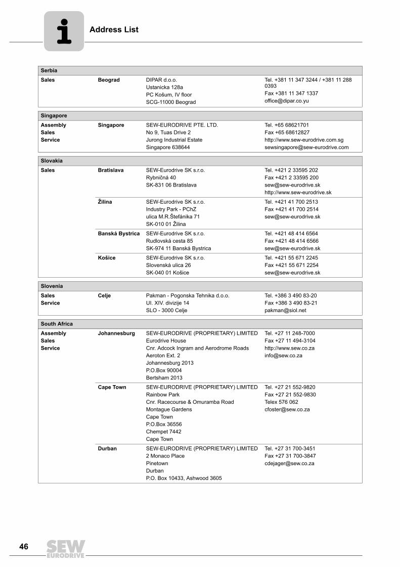
Serbia
Sales Beograd DIPAR d.o.o.Ustanicka 128aPC Košum, IV floorSCG-11000 Beograd
Tel. +381 11 347 3244 / +381 11 288 0393Fax +381 11 347 [email protected]
Singapore
AssemblySalesService
Singapore SEW-EURODRIVE PTE. LTD. No 9, Tuas Drive 2 Jurong Industrial Estate Singapore 638644
Tel. +65 68621701Fax +65 68612827http://[email protected]
Slovakia
Sales Bratislava SEW-Eurodrive SK s.r.o.Rybničná 40SK-831 06 Bratislava
Tel. +421 2 33595 202Fax +421 2 33595 [email protected]://www.sew-eurodrive.sk
Žilina SEW-Eurodrive SK s.r.o.Industry Park - PChZulica M.R.Štefánika 71SK-010 01 Žilina
Tel. +421 41 700 2513Fax +421 41 700 [email protected]
Banská Bystrica SEW-Eurodrive SK s.r.o.Rudlovská cesta 85SK-974 11 Banská Bystrica
Tel. +421 48 414 6564Fax +421 48 414 [email protected]
Košice SEW-Eurodrive SK s.r.o.Slovenská ulica 26SK-040 01 Košice
Tel. +421 55 671 2245Fax +421 55 671 [email protected]
Slovenia
SalesService
Celje Pakman - Pogonska Tehnika d.o.o.UI. XIV. divizije 14SLO - 3000 Celje
Tel. +386 3 490 83-20Fax +386 3 490 [email protected]
South Africa
AssemblySalesService
Johannesburg SEW-EURODRIVE (PROPRIETARY) LIMITEDEurodrive House Cnr. Adcock Ingram and Aerodrome RoadsAeroton Ext. 2Johannesburg 2013P.O.Box 90004Bertsham 2013
Tel. +27 11 248-7000Fax +27 11 494-3104http://[email protected]
Cape Town SEW-EURODRIVE (PROPRIETARY) LIMITED Rainbow ParkCnr. Racecourse & Omuramba RoadMontague GardensCape TownP.O.Box 36556Chempet 7442 Cape Town
Tel. +27 21 552-9820Fax +27 21 552-9830Telex 576 [email protected]
Durban SEW-EURODRIVE (PROPRIETARY) LIMITED2 Monaco PlacePinetownDurbanP.O. Box 10433, Ashwood 3605
Tel. +27 31 700-3451Fax +27 31 [email protected]

Address List
47
Spain
AssemblySalesService
Bilbao SEW-EURODRIVE ESPAÑA, S.L. Parque Tecnológico, Edificio, 302E-48170 Zamudio (Vizcaya)
Tel. +34 94 43184-70Fax +34 94 43184-71http://[email protected]
Sweden
AssemblySalesService
Jönköping SEW-EURODRIVE ABGnejsvägen 6-8S-55303 JönköpingBox 3100 S-55003 Jönköping
Tel. +46 36 3442 00Fax +46 36 3442 80http://[email protected]
Switzerland
AssemblySalesService
Basel Alfred lmhof A.G.Jurastrasse 10 CH-4142 Münchenstein bei Basel
Tel. +41 61 417 1717Fax +41 61 417 1700http://[email protected]
Thailand
AssemblySalesService
Chonburi SEW-EURODRIVE (Thailand) Ltd.700/456, Moo.7, DonhuarohMuang Chonburi 20000
Tel. +66 38 454281Fax +66 38 [email protected]
Tunisia
Sales Tunis T. M.S. Technic Marketing ServiceZone Industrielle Mghira 2Lot No. 392082 Fouchana
Tel. +216 71 4340-64 + 71 4320-29Fax +216 71 [email protected]
Turkey
AssemblySalesService
Istanbul SEW-EURODRIVE Hareket Sistemleri San. ve Tic. Ltd. Sti. Bagdat Cad. Koruma Cikmazi No. 3 TR-34846 Maltepe ISTANBUL
Tel. +90 216 4419163 / 4419164Fax +90 216 3055867http://[email protected]
Ukraine
SalesService
Dnepropetrovsk SEW-EURODRIVEStr. Rabochaja 23-B, Office 40949008 Dnepropetrovsk
Tel. +380 56 370 3211Fax +380 56 372 2078http://[email protected]
USA
ProductionAssemblySalesServiceCorporate Offices
Southeast Region
SEW-EURODRIVE INC. 1295 Old Spartanburg Highway P.O. Box 518Lyman, S.C. 29365
Tel. +1 864 439-7537Fax Sales +1 864 439-7830Fax Manufacturing +1 864 439-9948Fax Assembly +1 864 439-0566Fax Confidential/HR +1 864 949-5557http://[email protected]
AssemblySalesService
Northeast Region
SEW-EURODRIVE INC. Pureland Ind. Complex 2107 High Hill Road, P.O. Box 481Bridgeport, New Jersey 08014
Tel. +1 856 467-2277Fax +1 856 [email protected]
Midwest Region SEW-EURODRIVE INC.2001 West Main Street Troy, Ohio 45373
Tel. +1 937 335-0036Fax +1 937 [email protected]
Southwest Region
SEW-EURODRIVE INC.3950 Platinum Way Dallas, Texas 75237
Tel. +1 214 330-4824Fax +1 214 [email protected]

Address List
48
Western Region SEW-EURODRIVE INC. 30599 San Antonio St.Hayward, CA 94544
Tel. +1 510 487-3560Fax +1 510 [email protected]
Additional addresses for service in the USA provided on request!
Venezuela
AssemblySalesService
Valencia SEW-EURODRIVE Venezuela S.A.Av. Norte Sur No. 3, Galpon 84-319Zona Industrial Municipal NorteValencia, Estado Carabobo
Tel. +58 241 832-9804Fax +58 241 838-6275http://[email protected]@cantv.net
USA


SEW-EURODRIVE—Driving the world
SEW-EURODRIVEDriving the world
www.sew-eurodrive.com
SEW-EURODRIVE GmbH & Co KGP.O. Box 302376642 Bruchsal/GermanyPhone +49 7251 75-0Fax +49 7251 [email protected]