mounting of optical components - university of arizona · j. h. burge 5 • locating the lens with...
TRANSCRIPT

Mounting of Optical ComponentsMounting of lenses
Jim BurgeProfessor, Optical Sciences and AstronomyUniversity of ArizonaTucson, AZ [email protected]
Copyright 2011

J. H. Burge 2
Design approach for lens mounts
• Lenses are axisymmetric, usually with spherical surfaces
• Key drivers for design are centration and spacing tolerances
• Metal barrels can be machined so they are highly symmetric
1. Place one lens spherical surface onto a true surface on the barrel. This gives excellent accuracy at low cost.
2. Remaining degree of freedom is centration.
• Control by size of bore, lens, and tight tolerance, clamped or potted in place– direct centering error
– lens wedge
• Lens barrel is critical for control of stray light– Balance with optical design to maintain clear aperture, but limit strays
– Blacken edges of lenses that are illuminated or are viewed
– Cut threads on inside surfaces, blacken for good rejection
– Avoid specular reflections into the sensor, even from blackened surfaces
– Add baffle tube in front of lenses

J. H. Burge 3
• Using Surface Contact can help to accurately locate the optic correctly
Mount lenses using the optical surface
Fig. 2.4 Registering a poorly edged lens by its rim may result in tilt or decentration of the optical axis (b) decenter (c) tilt (d) tilt and decenter

J. H. Burge 4
• Mechanical surface can be in the wrong place with no negative consequences
Lens mounts: align the optical surfaces

J. H. Burge 5
• Locating the Lens with an axial preload can help to hold a lens in place against maximum acceleration as well.
Preload for lens mounts
Figure 2.12
Yoder, Mounting Optics In Optical Instruments 2nd Ed.

J. H. Burge 6
Lens seats

J. H. Burge 7
• Basic Type of Lens Seats:– Sharp Corner (R ~ 0.002” or 50 µm)
– Toroidal Lens Seat
– Conical or Tangential Seat
– Spherical Lens Seat
– Flat Lens Seat
• Sharp Corner Interfaces for Concave and Convex Surfaces
Lens interfaces: the sharp corner
Figure 3.26 Figure 3.27 Yoder, Mounting Optics In Optical Instruments 2nd Ed.

J. H. Burge 8
Issues with the sharp corner
• Provides highest accuracy, and is easy to verify
• Potentially large contact stresses– For most applications, these will not cause any risk
• Sharp corners are susceptible to damage or to burrs– Standard practice of “breaking corners” will result in loss of accuracy
• “Sharp” corner with radius > 0.002” can be considered as toroidal seat
REFERENCE SURFACE
dseatzseat zvertex
zsag(r)

J. H. Burge 9
Tensile stress, caused by contact stress
• The deformation due to point loading on a glass surface causes a localized tensile stress at the surface, a small distance from the load. The peak tensile stress T is estimated as
C is the peak compressive stress from the concentrated load is Poisson’s ratio for the glass
• This stress field is small, and shallow• This can be a concern for point loads, which can cause a conical fracture in the glass• The effect for line loads does not drive most designs• Verified by testing at UA. Unable to detect decreased strength, even after loading with
>50,000 psi
Finite element model of cylinder on flatR = 2”, 9 lb/in load
with <0.0001” elements3800 psi maximum compressive stress350 psi maximum tensile stress
0.015” from the load<0.001” deep
CT
321
Compressive stress
Tensile stress

Geometry for toroidal seats for lens mounts
r R
z
22 rRRzIf sharp corner is defined, but actual radius of is obtained, axial shift of lens, with respect to ideal, is
Rrz
Position of lens vertexdefined by toroidal interface
Toroidal interface, radius position defined by intersection of flat and cylindrical surfaces
Typical value for is 0.05 mm or 0.002”
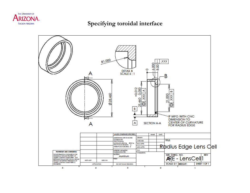
Specifying toroidal interface

J. H. Burge 12
• Reduce contact stress using conical interface– Note that this works only for convex surfaces
• It is harder to hold the lens spacing tolerances with conical seats
Conical interface, or tangent contact
Fig 3.28
Yoder, Mounting Optics In Optical Instruments 2nd Ed.
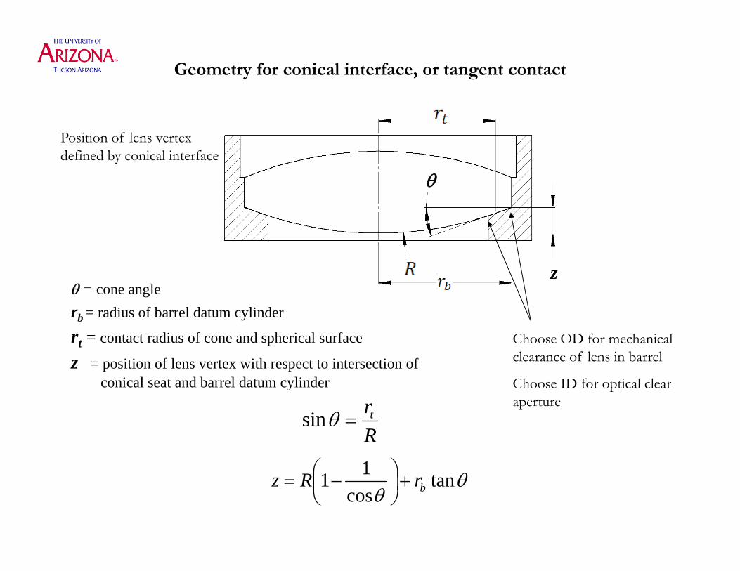
Geometry for conical interface, or tangent contact
Position of lens vertexdefined by conical interface
Choose OD for mechanical clearance of lens in barrel
Choose ID for optical clear aperture
= cone anglerb = radius of barrel datum cylinder
rt = contact radius of cone and spherical surface
z = position of lens vertex with respect to intersection of conical seat and barrel datum cylinder
Rrtsin
tancos
11 brRz
z
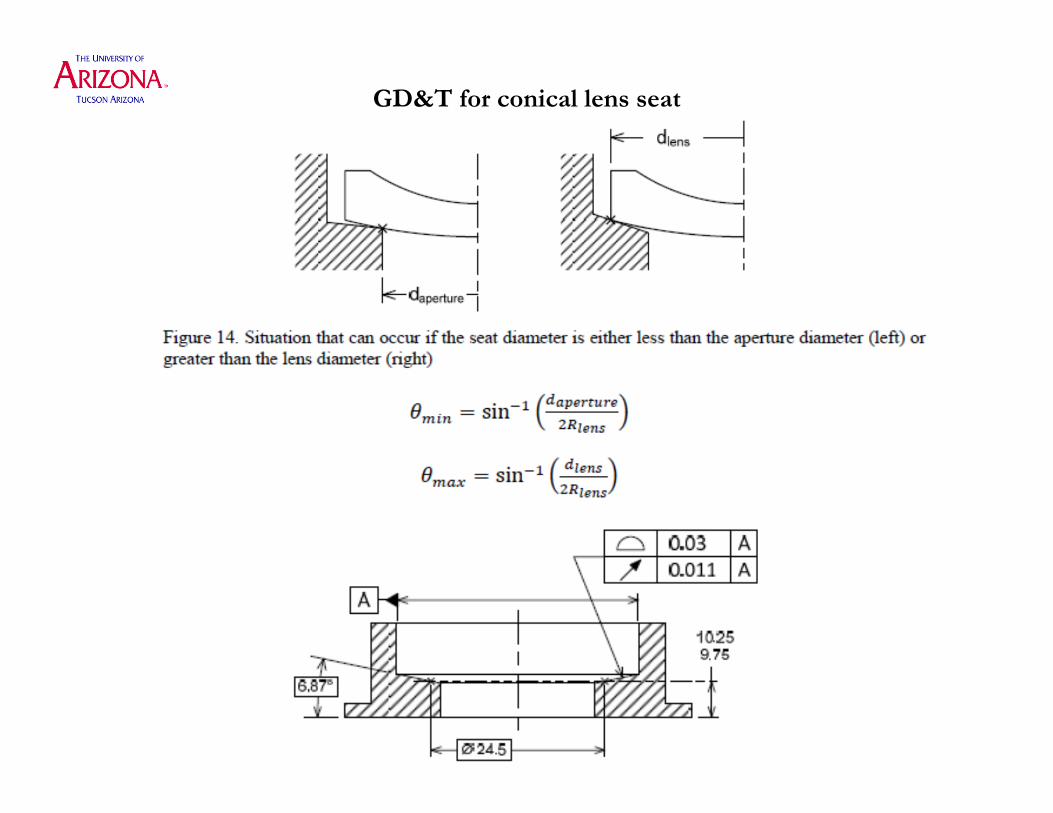
GD&T for conical lens seat

J. H. Burge 15
• Very benign, nominally zero stress concentration
• Difficult to manufacture and measure accurately. • Possible, but costs will be driven significantly by these interface types.
• Seldom justified
Spherical Seats
Figure 3.31
Yoder, Mounting Optics In Optical Instruments 2nd Ed.

J. H. Burge 16
• Edge Flat Seat and Various surfaces can be used for a lens mounting purposes. – Any mounting surfaces should be treated as precisely defined and oriented surfaces
– Uncertainty in cutting the mounting surface will directly affect lens position accuracy
Using mechanical surfaces for mounting interfaces
Figure 3.32
Figure 3.33
Yoder, Mounting Optics In Optical Instruments 2nd Ed.
J. H. Burge 17
Retainers
• The features in the lens barrels should define the lens position
• The retainers maintain a preload to hold the lens in place
• Types of retainers:• Burnished Edge
• Flexure
• Snap Ring
• Threaded Retainer
• Press Fit or Interference Fit Retainer
• Elastomeric Retainer

J. H. Burge 18
– The metal of the lens cell is either rolled or bent into the appropriate shape to hold the lens in place.
– Preloads and springs may be used as well
– Low cost for production
Lens retainer with burnished edge
Figure 3.39 Yoder, Mounting Optics In Optical Instruments 2nd Ed.

J. H. Burge 19
For larger lenses compliant spacers can be used under the mounting screws to help to distribute force more evenly around the optic being mounted
Provides good control of compliant preload
Increase part count and cost
Lens retainer with flexure ring
J. H. Burge 20
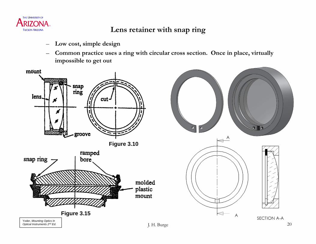
– Low cost, simple design
– Common practice uses a ring with circular cross section. Once in place, virtually impossible to get out
Lens retainer with snap ring
Figure 3.10
Figure 3.15 Yoder, Mounting Optics In Optical Instruments 2nd Ed.

J. H. Burge 21
• Easy design, easy to make
• Allows easy assembly and disassembly
Lens retainer using threaded ring
Figure 3.17
Figure 3.19
Yoder, Mounting Optics In Optical Instruments 2nd Ed.

J. H. Burge 22
Torque setting for retaining rings
P
Figure 3.18
Yoder, Mounting Optics In Optical Instruments 2nd Ed.

J. H. Burge 23
• Easy design, low cost production
• Difficult to control preload
• Difficult or impossible to disassemble
Lens retainer ring pressed in
Fig. 3.16
Yoder, Mounting Optics In Optical Instruments 2nd Ed.

J. H. Burge 24
Pot the lens in place
• Need to provide holes to inject adhesive
• Control adhesive flow during assembly. Don’t get it on the optical surface
Figure 3.36 Yoder, Mounting Optics In Optical Instruments 2nd Ed.
J. H. Burge 25
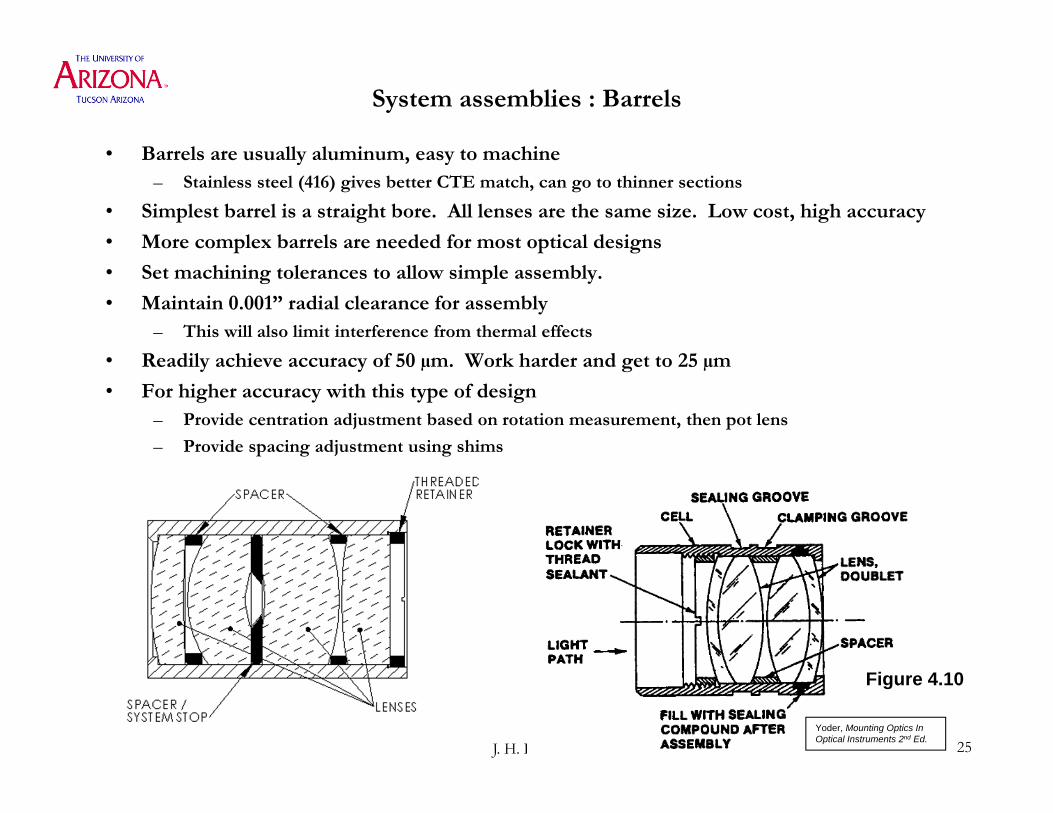
System assemblies : Barrels
• Barrels are usually aluminum, easy to machine– Stainless steel (416) gives better CTE match, can go to thinner sections
• Simplest barrel is a straight bore. All lenses are the same size. Low cost, high accuracy
• More complex barrels are needed for most optical designs
• Set machining tolerances to allow simple assembly.
• Maintain 0.001” radial clearance for assembly– This will also limit interference from thermal effects
• Readily achieve accuracy of 50 µm. Work harder and get to 25 µm
• For higher accuracy with this type of design– Provide centration adjustment based on rotation measurement, then pot lens
– Provide spacing adjustment using shims
Figure 4.10
Yoder, Mounting Optics In Optical Instruments 2nd Ed.

Easiest lens barrel
Lenses of Equal Diameter With Axial Position Defined by Spacers
• Precise bore is low cost operation
• Assembly is easy
• Rely on tolerances of lenses for centration
• Rely on tolerance of spacers for tilt, axial spacing
J. H. Burge 27
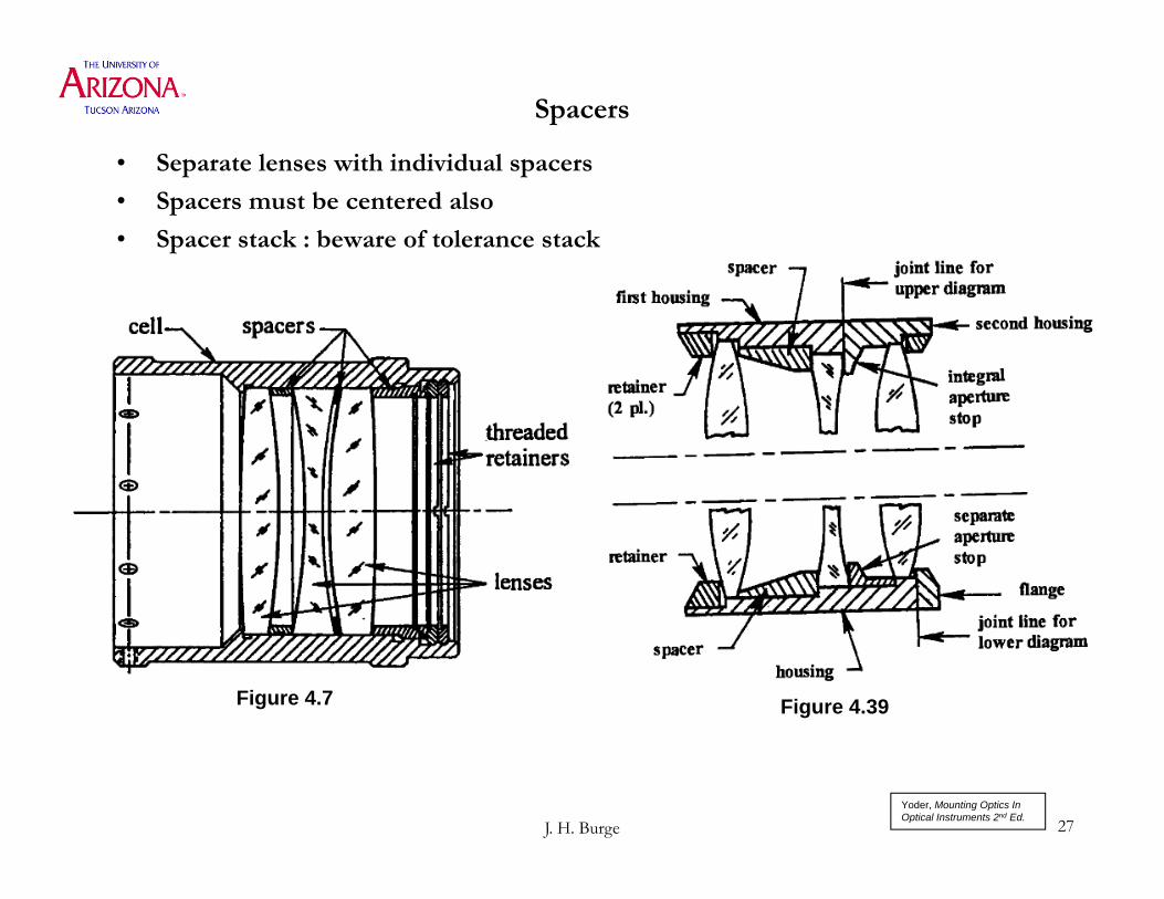
Spacers
• Separate lenses with individual spacers
• Spacers must be centered also
• Spacer stack : beware of tolerance stack
Figure 4.7 Figure 4.39
Yoder, Mounting Optics In Optical Instruments 2nd Ed.
J. H. Burge 28
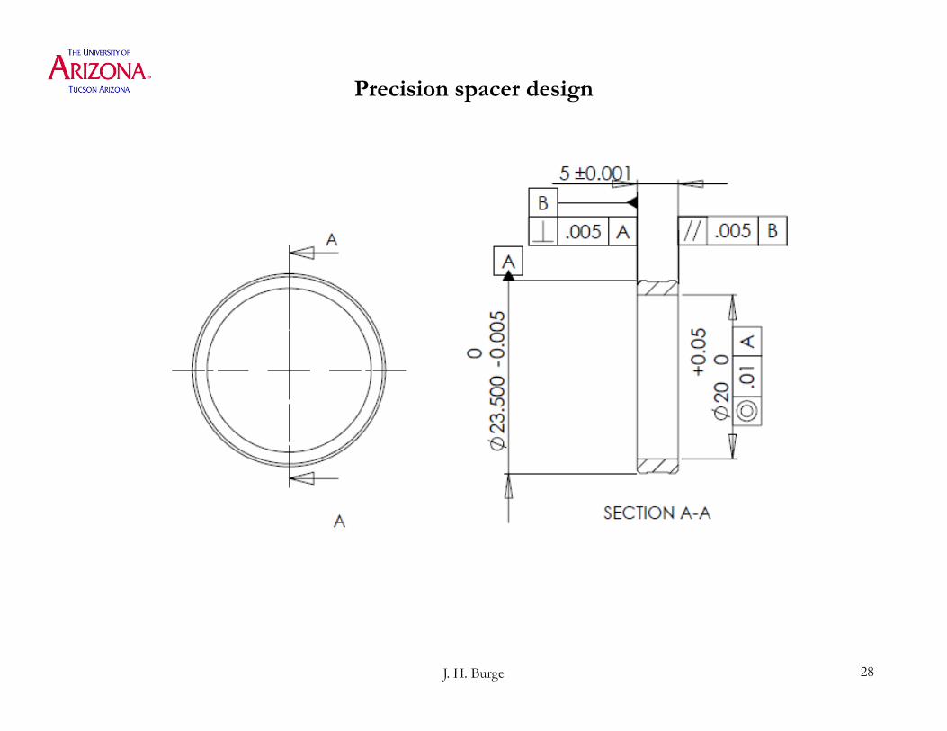
Precision spacer design

J. H. Burge 29
“Lathe” assembly
• Achieve high precision by customizing each barrel for the as-built lens elements
• Creates situation where parts are not interchangeable
Figure 4.11
Yoder, Mounting Optics In Optical Instruments 2nd Ed.

J. H. Burge 30
• No spacers needed
• Lens positions defined by barrel machining
• Each lens needs retainer or adhesive
Lenses With Varied Diameters

Two Part Lens Barrel
• The centration is defined by the toroidal interface– Allows tight fit (+/-0.002 mm), yet allows assembly
• The axial position and tilt are defined with the plane surfaces
J. H. Burge 31

Use of gauges for lens barrels
• The use of a gauge to verify your manufactured parts can improve accuracy
• Sacrificial Lenses or Gauges Manufactured to the specified radius or shape can be used
J. H. Burge 32
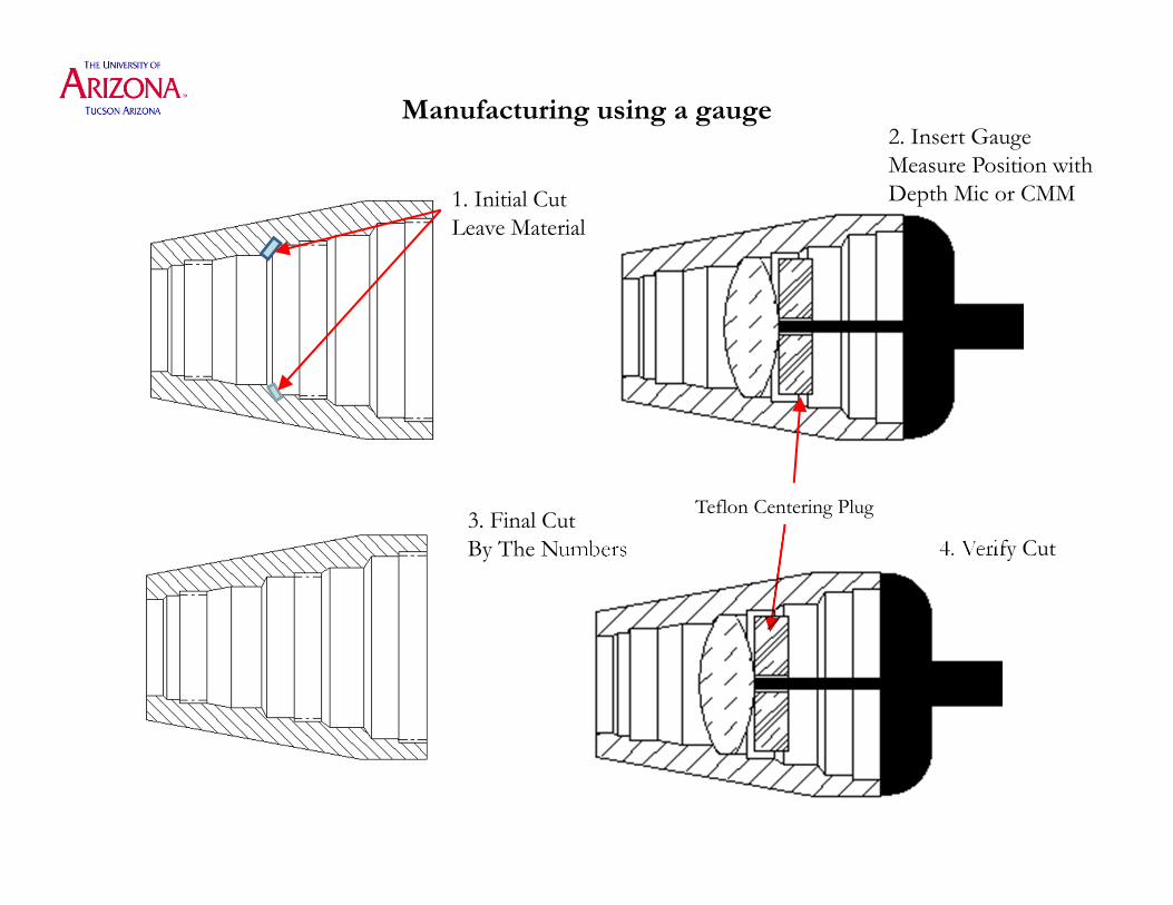
Manufacturing using a gauge
1. Initial CutLeave Material
2. Insert GaugeMeasure Position withDepth Mic or CMM
3. Final CutBy The Numbers 4. Verify Cut
Teflon Centering Plug

J. H. Burge 34
Alignment of individual elements
• Achieve tighter tolerances by adjusting lens centration, rather than relying on machining tolerances
• Spin up lens system on air bearing, adjust lens centration and pot lenses in place
Figure 4.13 Yoder, Mounting Optics In Optical Instruments 2nd Ed.

J. H. Burge 35
Alignment of elements
• Alignment with Push Screws
• Use mechanical or optical measurementof wobble as the barrel is rotated
• Once aligned, pot the element in place
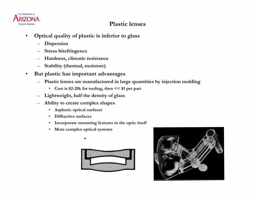
Plastic lenses
• Optical quality of plastic is inferior to glass– Dispersion
– Stress birefringence
– Hardness, climatic resistance
– Stability (thermal, moisture)
• But plastic has important advantages– Plastic lenses are manufactured in large quantities by injection molding
• Cost is $2-20k for tooling, then << $1 per part
– Lightweight, half the density of glass
– Ability to create complex shapes• Aspheric optical surfaces
• Diffractive surfaces
• Incorporate mounting features in the optic itself
• More complex optical systems

J. H. Burge 37
Groups of lenses• Tolerances are always tighter for element within a group. Group-to-group
alignment requirements are looser. Watch for this
From Yoder Mounting Optics in Optical Instruments 1st EditionSee Figure 4.52 in Yoder’s 2nd Edition on pg 173 for more.
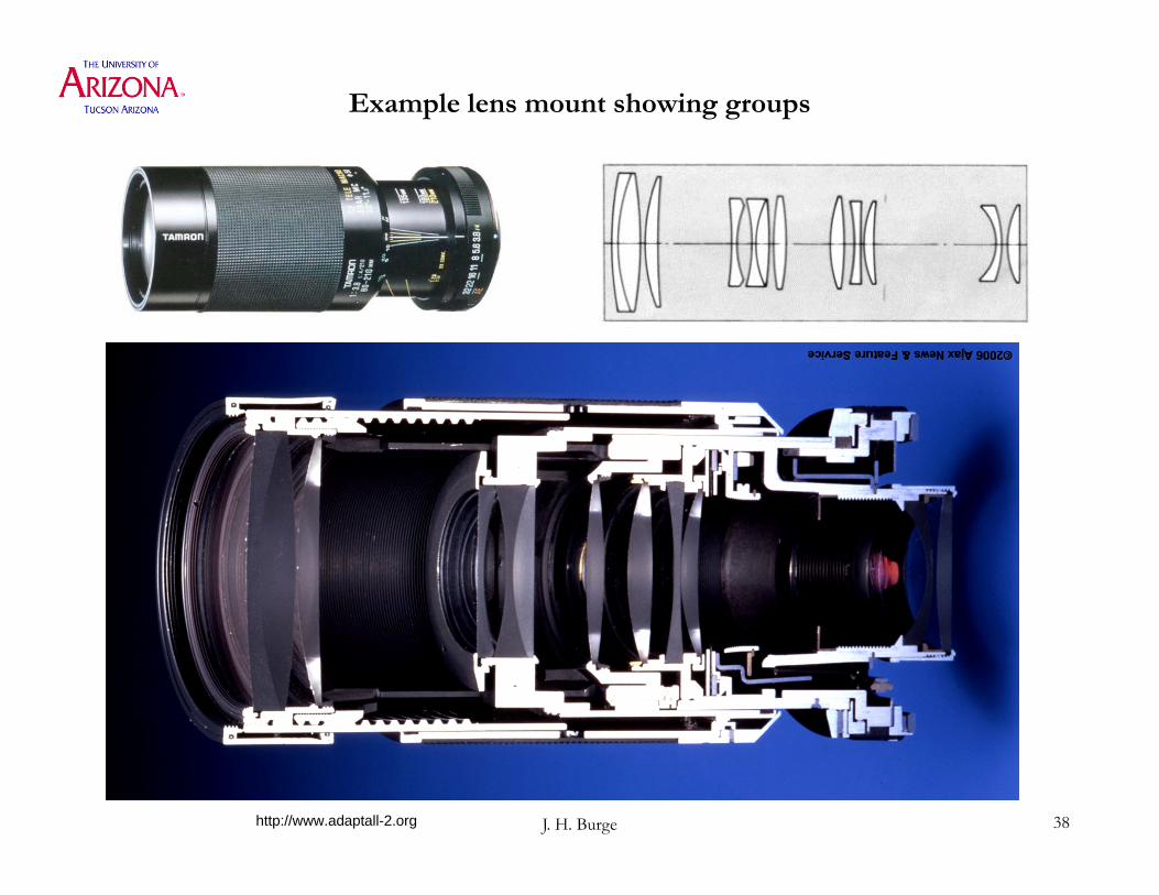
J. H. Burge 38
Example lens mount showing groups
http://www.adaptall-2.org

J. H. Burge 39
Multi-element lens in groups
http://www.kenrockwell.com
J. H. Burge 40
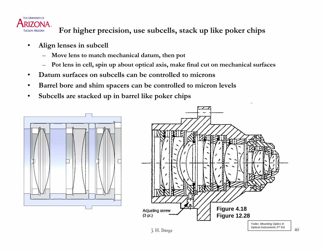
For higher precision, use subcells, stack up like poker chips
• Align lenses in subcell – Move lens to match mechanical datum, then pot
– Pot lens in cell, spin up about optical axis, make final cut on mechanical surfaces
• Datum surfaces on subcells can be controlled to microns
• Barrel bore and shim spacers can be controlled to micron levels
• Subcells are stacked up in barrel like poker chips
Figure 4.18 Figure 12.28
Yoder, Mounting Optics In Optical Instruments 2nd Ed.

J. H. Burge 41
Alignment of lens into subcell
Figure 12.9Yoder, Mounting Optics In Optical Instruments 2nd Ed.

J. H. Burge 42
Fine spacing adjustment using shims
• Alignment use of Shims
Fig. 12.29
Yoder, Mounting Optics In Optical Instruments 2nd Ed.
J. H. Burge 43
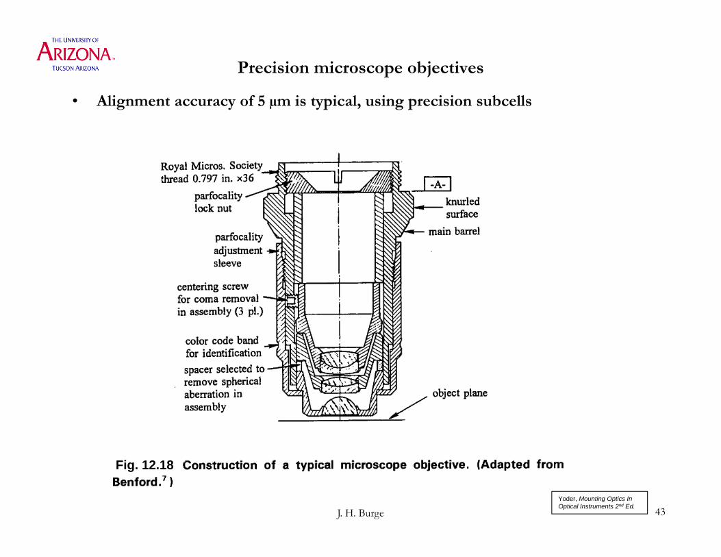
Precision microscope objectives
• Alignment accuracy of 5 µm is typical, using precision subcells
Fig. 12.18
Yoder, Mounting Optics In Optical Instruments 2nd Ed.

J. H. Burge 44
Recap: Lens mounting methods
In order of increasing precision, complexity, and cost• Straight barrel : All lenses same diameter
– Simple low cost bore. Use spacers and retaining ring.– Easy assembly, can be automated– Precision is limited mostly be the precision of the elements, including stack up of errors
• Stepped barrel : Accommodate lenses with varying sizes– More complex machining. Use sharp contact for highest accuracy.– Easy assembly, can be automated– Precision is limited by the machining. 50 µm is common, 10 µm is possible.
• Add centration adjustment to elements using rotation + optical measurement– Labor intensive assembly– Achieve 10 µm easily, 1 µm is possible
• Spacing adjustment with shims– Choose custom spacer based n measurement– Labor intensive assembly– Achieve 25 µm easily, 5 µm is possible
• Spacing compensation using as-built data– Labor intensive assembly– Achieve 25 µm easily, 5 µm is possible
• Mount elements in sub-cell, stack up for assembly– Very labor intensive, expensive– Achieve 10 µm easily, <1 µm is possible

J. H. Burge 45
Thermal stress for bonded lenses
• Achieve low stress mount by controlling the bond dimension
• As temperature increase, metal expands more then glass, opening up the gap.
• Use adhesive with high CTE that expands with the correct proportion to fill the gap in a stress-free state
Figure 3.36
Yoder, Mounting Optics In Optical Instruments 2nd Ed.

J. H. Burge 46
Provide thermal isolation using radial flexures
Figure 3.43
Yoder, Mounting Optics In Optical Instruments 2nd Ed.